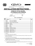
1
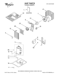
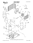
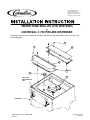
IMI CORNELIUS INC. One Cornelius Place Anoka. MN 55303-6234 Telephone (800) 238–3600 Facsimile (763) 422–3246 WATER TANK SEAL KIT (P/N 308979000) on UNIVERSAL C-750 PRE-MIX DISPENSER These Instructions outline installation of the Water Tank Seal Kit (P/N 308979000) on the Universal C-750 Pre-Mix Dispenser. 1 1 3 2 NO TAG 4 5 INSULATED REFRIGERATION LINE DISPENSER IMI Cornelius Inc, 1989–2002 Revision: A November 13, 2002 185211001 NOTE: Only qualified personnel should install this kit. 1. Unpack loose–shipped parts. Make sure all parts are present and in good condition. Table 1. Loose-Shipped Parts Item No. Part No. Name Qty. 1 200468012 Sheet Metal Screw, Phil Truss Hd, No. 8 by 3/4-in. 12 2 308981044 Front Cover Plate 1 3 308982044 Back Cover Plate 1 4 313093000 Plug, 2-in. 1 5 172127000 Plug 1 6 960265000 Permagum Sealer,12-in. long 1 8 960115000 Rubatex Insulation,1/8 by 1/2-in. (78-in. long) 1 INSTALLING WATER TANK SEAL KIT IMPORTANT: This kit is intended to seal the water tank to prevent leakage from splashing water when moving or transporting the Dispenser. IT IS NOT INTENDED THAT THE DISPENSER MAY BE LAID ON IT’S SIDE WHEN WATER TANK IS FULL OF WATER. 1. If Dispenser is in operation, place power switch on back of Dispenser in ‘‘OFF’’ position. 2. Remove four screws securing Dispenser top cover, then lift cover straight up and off. NOTE: Front of Dispenser is the side facing the dispensing valves. 3. Place RUBATEX INSULATION (item NO TAG) all the way around outer edges of FRONT COVER PLATE (item 2) and BACK COVER PLATE (item 3) as shown in illustration. FILL ANY GAPS AT BUTT EDGES OF RUBATEX INSULATION WITH SMALL PIECES OF PERMAGUM SEALER (item 6). 4. Place FRONT COVER PLATE (item 2) in position on top of water tank as shown in illustration. IT MAY BE NECESSARY TO VERY CAREFULLY REFORM OR REPOSITION INSULATED REFRIGERATION LINE ANGLE TO FIT INTO CUTOUT AREA IN CORNER OF FRONT COVER PLATE. 5. Secure back side of front cover plate to agitator motor support plate with four THREAD CUTTING SCREWS (item NO TAG). 6. Secure rest of front cover plate to plastic motor tank rim with six SHEET METAL SCREWS (item 1). DO NOT OVERTIGHTEN SCREWS INTO PLASTIC. 7. Place BACK COVER PLATE (item 3) in position on top of water tank as shown in illustration. 8. Secure front side of back cover plate to agitator motor support plate with four THREAD CUTTING SCREWS (item NO TAG). 9. Secure rest of back cover plate to plastic water tank rim with five SHEET METAL SCREWS (item 1). DO NOT OVERTIGHTEN SCREWS INTO PLASTIC. 10. Place PLUG (item 4) in agitator motor plate water fill hole. 185211001 2 11. If installing kit on a four-flavor Dispenser, install PLUG (item 5) in 1/2-inch hole in top of agitator motor plate. 12. Fill area between insulated refrigeration line and cutout area in front cover plate with PERMAGUM SEALER (item 6). Also, overlap front cover plate and insulated refrigeration line with permagum sealer to prevent water leak. 13. If new Dispenser installation, refer to manual provided with Dispenser and complete installation as instructed. 14. Install Dispenser top cover and secure with four screws. 15. If Dispenser was in operation before start of Kit installation, place power switch in ‘‘ON’’ position. 3 185211001