1
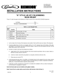
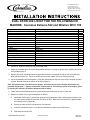
IMI CORNELIUS INC.
One Cornelius Place
Anoka. MN 55303-6234
Telephone (800) 238–3600
Facsimile (763) 422–3246
DUAL DF/ED 2XX LID KIT FOR THE FOLLOWING ICE
MAKERS: Cornelius Extreme 522 and Wilshire WCC 700
Dispenser
Kit Number
DF/ED 2XX
629087947
Components
1. Cover
2. Lid Assembly (XAC 522 Icemaker)
3. Lid Assembly (WCC 700 Icemaker)
4. Mounting Bracket
5. Screw, #8 SM
6. RTV
7. Label
8. Instructions
9. Nut, Nylon
10. Washer, Nylon
11. Washer, Sealing
12. Ice Baffle
13. Gasket Strip
14. Binstat Kit
15. Plate, Top Cover
620043547
620046064
620046060
22127
70217
50904
91957
620919550
620701902
620701903
620701901
620037003
620505802
631500109
620044644
Qty
2
1
1
4
20
1
2
1
4
4
4
2
2
1
1
1. Unpack kit. Refer to Figures 1 & 2 for component detail.
2. Attach the ice baffles (item 12) to the lid assemblies (items 2 & 3) using the gasket strips, washers and acorn
nuts provided (figure 1).
3. Replace the center–mounting bracket supplied with the dual merchandiser kit with the top cover plate supplied with this kit (item 15). Failure to do this will prevent the adapter kit from functioning properly.
4. Set the lid assembly onto the dispenser. Using the slotted holes on the side of the lid as a template, drill four
(4) 9/64” diameter holes at the bottom of the slots (Figure 2).
Note: Use extreme care not to drill into the hopper. Use a drill stop to ensure that the drill bit does not
penetrate deeper than ¼” past the sheet metal. Failure to do so could result in a hole in the hopper, greatly reducing the efficiency of both the dispenser and ice maker.
5. Fasten the lid to the dispenser with four (4) #8 sheet metal screws (item 5), two on each side.
6. Seal the ice maker to the top of the dispenser as follows:
A.
Run beads of RTV (item 7) around the opening in the lid assembly and the inside of the perimeter of the
ice maker outline so that the ice maker will set on the RTV. Make sure that some RTV is applied inside
the nutserts on the lid assembly.
B.
Set the ice maker onto the lid and position it as required.
C.
Insert the thumbscrews (item 5) into the lid to attach the icemaker to the lid (Figure 3).
D.
Wipe away the excess RTV.
EIMI Cornelius Inc; 2001
November 30, 2001
Revision A
620919550
7. Attach the mounting brackets (item 4) to the to the ice makers and lid assemblies with the the #8 sheet metal
screws (item 5) (figure 2).
8. Follow the ice maker manufacturer’s instructions to complete the installation of the ice maker.
9. Install the bin–stat (item 14) per the instructions provided with that kit.
10. Install the covers (item 1) into the slots on the lid assemblies (figure 3).
11. Apply the label (item 6) on the front of the cover.
EIMI Cornelius Inc; 2001
November 30, 2001
Revision A
620919550
10
11
9
13
12
SECTION
W–W
SCALE 0.625
9
4X
4X
4X
10
11
2X
2X
13
12
FIGURE 1. PARTS
EIMI Cornelius Inc; 2001
November 30, 2001
Revision A
620919550
DRILL ø 9/64 (.140) HOLES
WCC700 ICEMAKER
USING BOTTOM OF SLOTTED
HOLES AS A TEMPLATE.
EXTREME 522 ICEMAKER
VIEW X
4 4X
SCALE 0.250
5 16X
2X
2X
SEE FIGURE(S) 3a
7
1
& 3b
3
2
SEAL ICEMAKER(S) TO
ITEM 2 AND 3 WITH
ITEM 6 (RTV)
5 4X
REPLACE ITEM 5–ED2XX DUAL–LIGHTED
MERCHANDISER KIT WITH
P/N 620044644
SEE VIEW ”X”
FIGURE 2. DISPENSER ASSEMBLY
EIMI Cornelius Inc; 2001
November 30, 2001
Revision A
620919550
EXTREME 522 ICEMAKER
WCC700 ICEMAKER
1
LID ASSEMBLY
FIGURE 3a. CLOSED POSITION
SCALE
0.250
WCC700 ICEMAKER
EXTREME 522 ICEMAKER
1
LID ASSEMBLY
FIGURE 3b. OPEN POSITION
SCALE
EIMI Cornelius Inc; 2001
0.250
November 30, 2001
Revision A
620919550


![WCC-700 Service Manual [ 058047 ]](http://vs1.manualzilla.com/store/data/006032662_1-9beff2067bf07b85dc4c0d9ee1d42eb7-150x150.png)