1
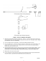
IMI CORNELIUS INC g One Cornelius Place g Anoka, MN 55303-6234
Telephone (800) 238-3600
Facsimile (800) 535–4231
INSTALLATION INSTRUCTIONS FOR
PRESSURE SWITCH PCL KIT (569000689)
Table 1. Loose-Shipped Parts
Item
No.
Part No.
Name
Qty.
1
560002361
Board Circ Prod Delivery
2
2
560004158
Chip Micro EPROM Main
1
3
560002360
Board Circ Oper Interface
1
4
560006424
Switch Press Syr 30-37 PSI
2
5
560005312
Fitg T 7/16-20 x 1/8-FPT
2
6
560002318
Fitg Push PI4512F4S .375 x .25
4
7
560006985
Harn Adaptor Press Switch
2
8
560002388
Tube Prod .250 I.D. x 22-1/2”
1
9
560002389
Tube Prod .250 I.D. x 20-1/2”
1
10
560002339
Clip Flow Bend .375 O.D. Tube
2
11
4417
Clip Lock .375 O.D. Push-in Fitg
4
12
690945000
Tie Cable
2
1. Obtain wakeup time, sleep time, defrost times, and viscosity settings from current setup.
2. Disconnect power (unit may have to be pulled from wall to access electrical outlet).
3. Shut off syrup supply by shutting down CO2. Bleed CO2 from inlets to BIB pumps.
4. Remove left side, front access and rear panel.
5. Remove No. 1 cylinder syrup inlet line and No. 1 syrup flow sensor assembly (leftmost if facing unit).
6. Install new syrup inlet line (2 flavor OC unit), or connect existing line with tubing elbow and cable tie (2 and
4 flavor standing units) to pressure switch assembly (see Figure 1). Assemble locks onto pressure switch
assembly and reconnect electrical harness paying close attention to maintaining wiring integrity. Switch is
supplied with adapter harness to retrofit existing wiring (wires to be attached to “C” common and “NC” normally closed. Note: some parts will be left over.
7. Repeat steps 5 and 6 for No. 2, 3 and 4 syrup inlet lines and syrup flow sensor assemblies.
8. Remove existing main control board EPROM chip using an EPROM extraction tool. Install EPROM taking
great care not to misalign pins or cause damage to chip. Note: wearing ground strap is stronly recommended to protect board from electrostatic discharge. Take care to put each connector back in its
proper location.
9. Remove existing No. 1 cylinder product delivery board. Install new product delivery board (using ground
strap). Take care to put each connector back in its proper location.
10. Repeat step 9 for product delivery boards No. 2, 3 and 4.
569000338
Page 1 of 2
Revised: October 9, 2003
January 23, 2002
9
8
4
FCB Countertop Product Plumbing Components
10
5
6
11
12
FCB Standing Product Plumbing Components
FIGURE 1. PRODUCT PLUMBING COMPONENTS
11. Remove the existing display board for cylinders No. 1 and No. 2. Install new display board, removing protective coating on lens. Pay special attention to putting the connectors back in the proper location. Repeat
for cylinders No. 3 and No. 4 (if applicable).
12. Turn CO2 supply back on to syrup pumps. Visually check soldout connections for leaks.
13. Turn main power back on. Set clock, wakeup time sleep time, defrost time(s) and viscosity settings. Turn
barrels to “ON” and let unit cycle. Draw a couple of drinks from each barrel to verify proper operation.
Double check syrup connection for leak.
14. Disconnect BIB connector from each syrup line (or pinch line closed to simulate soldout condition). Draw a
couple of drinks from each barrel to verify soldout condition occurs. Pay close attention that the correct
barrel soldout is lit to verify wiring integrity. Reconnect BIB connectors and verify that soldouts clear.
15. Replace side, front access and rear panels.
16. Pack circuit boards into the protective packaging from the replacement boards for return to IMI Cornelius.
Scrap flow sensors, syrup inlet lines that were removed and any leftover parts.
Page 2 of 2
569000338