1
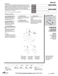
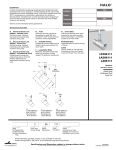
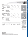
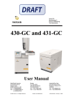
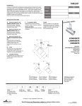
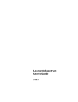
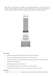
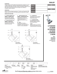
HALO
®
DESCRIPTION
A series of lampholders employing simple geometric shapes that create
bold statements in any application. Tool less lockable tilt and rotation with
graduations for precise, repeatable aiming. Three media capable, these
70W T6 metal halide lampholders are comfortable in applications from
Gallery to Specialty Retail. Threaded screw-on bezel provides positive
engagement, and removable beveled spacer creates an attractive look when
multiple media are not required.
Ideal for accent and display lighting applications.
Type
Catalog #
Project
Date
Comments
Prepared by
SPECIFICATION FEATURES
A ... Electrical Quick Lock
Adapter - Flexible Track
Die Cast housing. Attaches
electrically and mechanically
anywhere along Flexible Track.
Includes integral electronic ballast.
B ... Electrical Quick Lock
Adapter - Power Trac
Die cast housing. Attaches
electrically and mechanically
anywhere along Power trac.
Includes integral electronic ballast.
F ... Lockable Aiming
Lampholder tilt and rotation can be
locked in place without the use of
tools.
G ... Graduated Dials
Graduated dials for precise and
consistent aiming of fixtures.
G
C ... Electrical Quick Lock
Adapter - Architectural Track
Polycarbonate housing with
integral fuse and on-off switch.
Attaches electrically and
mechanically anywhere along
Architectural Linear Track.
Includes integral electronic ballast.
Labels
UL/c-UL Listed for use with Halo
Architectural Linear and Flexible
Track, Halo Power-Trac, and Lazer.
EMI/RFI complies with FCC 18C,
non-consumer limits.
A
LF506670
L506670
LA506670
F
D
Max
Extension
Synchro
70W T6 Metal Halide Accent
E
D ... Lampholder Body
Machined, Extruded and Die Cast
Aluminum cylinders includes
integral electronic ballast.
L
Flexible Track
Power-Trac
Architectural Track
W
E ... Cover Glass
Fixture provided with cover glass
(required for use with non-open
fixture rated lamps).
C
B
LF
L=13.12" [333mm]
W=5.5" [140mm]
Max Extension=
16.25" [333mm]
5
Track
LF=Flexible Track
L=Halo Power-Trac
LA=Halo
Architectural
Track
06
Lamp Type
5=Metal Halide
L
L=13.12" [333mm]
W=5.5" [140mm]
Max Extension=
16.25" [333mm]
6
Series
06=Synchro
Beam
SP=Spot
FL=Flood
NF=Narrow
Flood
LA
L=13.12" [333mm]
W=5.5" [140mm]
Max Extension=
16.25" [333mm]
70W Electronic Ballast
Power Factor: 0.95
Total Input Watts: 79
Max Amps: 0.67
THD:<15%
70
Lamp
Wattage
6=T6
70=70W
Ceramic
Metal halide
Finish
Voltage
AH=Aluminum Haze
LA only
Blank=120V
P=White (L and LA only)
MB=Black (L and LA only)
• Product is only available in 120 volts.
Specifications and Dimensions subject to change without notice.
Consult your representative for additional options and finishes.
ADV050040
07/02/2008 12:03:12 PM
LF506670 L506670 LA506670
ACCESSORIES
ACCESSORIES
LA2C0
oR
l oI ErS F i l t e r s
C0
E SC
SO
L211=Medium Pink Color Filter
L 2 0 0 C o Red
l o r Color
Filte
rs
L212=Warm
Filter
L214=Ultraviolet
FilterColor Filter
L211=Medium Pink
LL212=Warm
200 Colo
r FColor
iColor
l t e rFilter
sFilter
L220=Daylight
Blue
Red
L221=Medium
Blue
Color
L214=Ultraviolet
Filter
L211=Medium
Pink
ColorFilter
Filter
L231=Medium
Amber
Color
Filter
L220=Daylight
Blue
Color
Filter
L212=Warm
Red
Color
Filter
L241=Medium
Color Filter
Filter
L221=MediumGreen
Blue
Color
L214=Ultraviolet
Filter
L231=Medium Blue
Amber
Color
Filter
L220=Daylight
Color
Filter
L241=Medium Blue
Green
Color
Filter
L221=Medium
Color
Filter
L231=Medium Amber Color Filter
L241=Medium Green Color Filter
4 11/16"
[19mm]
4 11/16"
[19mm]
1/4"
[6mm]
4 11/16"
[19mm]
1/4"
[6mm]
L200 Series Color
L200 SeriesFilters
Color
1/4"
[6mm]
Filters
L200 Series Color
Filters
L200 Series Optical Lenses
L210=Linear Spread Lens
L 2 0lens
0 S fans
e r i eout
s Olight
ptic
a l L 55°
e n s- e27
s 1/2° each side of
L210
beam
center
L210=Linear Spread Lens
LL210
2 0 0lens
S efans
r Spread
i e sout
Op
t i c beam
a l L e55°
n s e- s27 1/2° each side of
light
L215=Radial
Lens
center
L210=Linear
Spread
Lens
L215
lens spreads
light
beam 30° in all directions - 15° on
L210
lens
out light
beam 55° - 27 1/2° each side of
all
sides
of fans
center
L215=Radial
Spread
Lens
center
L215
lens
spreads
light
beam
30° in all directions - 15° on
L250=Linear Spread Lens
all sides
center
L215=Radial
Spread
Lens
L250
lens of
spreads
light
beam in one direction
L215
lens spreads
light
beam 30° in all directions - 15° on
L250=Linear
Spread
Lens
L265=Prismatic
Spread
Lens
all
sides
of
center
L250
lens
spreads
light
in one direction
L265 Spreads light beambeam
in all directions
L250=Linear
Spread
Lens
L265=Prismatic
Spread
Lens
L250
spreads
beam
one direction
L265 lens
Spreads
lightlight
beam
in allindirections
L265=Prismatic Spread Lens
LL265
2 7 5 Spreads
Cube C
e l l beam
L o u vine all
r directions
light
4 3/4" OD (121mm). Black finish 1/2"
L 2 7for
5 directing
C u b e C light
e l l Land
ouv
er
cells
eliminating
glare.
4 3/4" OD (121mm). Black finish 1/2"
and
Lcells
2 7 5forCdirecting
u b e C e light
ll Lo
u v eliminating
er
4glare.
3/4" OD (121mm). Black finish 1/2"
cells for directing light and eliminating
glare.
1/4"
[6mm]
1/4"
[6mm]
4 11/16"
[119mm]
4 11/16"
[119mm]
1/4"
[6mm]
1/4"
[6mm]
4 11/16"
[119mm]
1/4"
[6mm]
1/4"
[6mm]
L200 Lenses
L200 Lenses
L200 Lenses
4 3/4"
3/8"
(121mm) (10mm)
4 3/4"
3/8"
(121mm) (10mm)
4 3/4"
3/8"
(121mm) (10mm)
7/16"
(11mm)
7/16"
(11mm)
7/16"
(11mm)
L275 Cube
Louver
L275
Cube
Louver
L275 Cube
Louver
Remove beveled spacer when 2 or 3 media are used.
Specifications and Dimensions subject to change without notice.
HALO Track • Customer First Center • 1121 Highway 74 South • Peachtree City, GA 30269 • TEL 770.486.4800 • FAX 770.486.4801
ADV050040
07/02/2008 12:03:12 PM