1
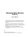
Vibrating Wire Monitor
VWM-005
User's Manual
This document refers to the VMW-005 5-wire Vibrating Wire Monitor delivered
to Argonne National Laboratory in 2007 to measure the profile of photon
beams on the Advanced Light Source. The APS scientist who evaluated it is
Glenn Decker.
The electronics circuits and chassis described in this User's Manual are
prototypes now replaced by modular electronics. The new electronics operate
on the same principle for frequency measurement. Their differences from the
prototype are:
• Front-end VWM placed near the sensor supporting two wires each are
powered via a long (up to 50m) cable to the VWM chassis.
• A VWM chassis controls up to 8 front-ends, i.e. 16 wires, providing data
readout via USB.
2007
HTM Reetz GmbH, Berlin, Germany
In cooperation with Yerevan Physics Institute, Yerevan, Armenia
Vibrating Wire Monitor
VWM-005
5 Wire Vibrating Wire Monitor
Specifications
SENSOR
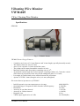
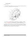
Fig. 1. VWM005 Sensor.
VWM005 Sensor Design Features
5 stainless steel wires of 0.1 mm diameter and 36 mm length, specially thermally treated;
The distance between wires 0.5 mm;
Area of wire exposure is 8 mm around the center;
The pickup can be rotated around the central wire axis;
Maximal rotation angle from plane containing wires is 450;
At maximal rotation angle the vertical aperture of pickup window is 2.5 mm; the vertical
offset between projections of the wires on the orthogonal plane is 0.35 mm;
Less angle of rotation leads to less offsets between the projections.
Aperure of VWM - 8mm (along the wires) x 6 mm (orthogonal)
Electromechanical parameters of VWM005
Initial frequencies at room temperature are in range
Operating range of frequencies shifts from the initial frequency
Resolution
Accuracy in one-hour interval
Accuracy in 24-hour interval
Response time
VWM output signal noise at 10 Hz
4000-9000 Hz;
0-1000 Hz;
0.01 Hz;
± 0.01 Hz;
± 0.04 Hz;
0.26 s;
0.01 Hz/Rt(Hz)
______________________________________________________________________________
VWM005 User's Manual
2
Thermal characteristics of VWM005
Thermal characteristics of VWM005 are defined by the factor of frequency dependence on mean
temperature of the wire overheating - 40.2 Hz/K at frequency 4200 Hz.
Operation range of wire overheating
Wire temperature resolution
Wire temperature accuracy in 1-hour interval measurement
Wire temperature accuracy in 24-hour interval measurement
0-25 K;
0.00025 К;
± 0.00025 K;
± 0.001 K;
Power characteristics of VWM005
Power characteristics of VWM005 are determined by the factor of frequency dependence on the
power deposited on the wire in the form of the heat at the interaction of photon beam with the
wire material in air- 9.3 Hz/mW.
Operational range of deposited power
Resolution of deposited power
Resolution of deposited power in 1-hour interval operation
Resolution of deposited power in 24-hour interval operation
Nonlinearity of the pickup in operational range of deposited power
ΔTmean/ΔQ = 0.23 K/mW
0-100 mW;
1 µW;
± 1 µW;
± 4.3 µW;
0.01 %.
ELECTRONIC UNIT
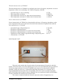
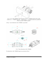
Fig. 2. VWM005 Electronic Unit.
Electronic unit contains the electronic plates for measurement of frequencies and their
transfer. Electronic unit is to be line supplied 110 to 230 VAC 60/50 Hz Beside the net connector
It also has a 8-pin connector for sensor, a SUBD 9 pin connector for data transfer in RS422
standard, 5 LEDs for each wire, 2 small LEDs indicating data transfer to or from the unit. 5
larger LEDs blink when the data from corresponding wire of the sensor is transferred. Small
green LED blinks when all data in current sampling cycle are transferred. Small red LED blinks
if some commands are transferred to electronic unit.
The sensor is connected with the electronic unit with a cable of length about 1 m.
______________________________________________________________________________
VWM005 User's Manual
3
It is strongly recommended to provide possibility of eletronic unit remote switching
on/off (for intrinsic microcontrollers reset).
MOUNTING
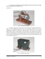
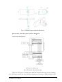
Fig. 3. VWM005 Mounting.
The sensor is mounted on a copper support for better thermal coupling with the flange on
which it will be installed. The pickup can be turned around the central wire (the axis of
symmetry of the cylindrical pickup). The wires are shifted along the line AA. For better
correspondence with the feed opening on the horizontal plate (3 on the figure) of the support the
distance between the face of the pickup (1) and the surface of the vertical plate (2) must be
19 mm. Also the number of the sensor (4) and numbers of the first and fifth (5) are marked. For
convenience of disassemble on one side of the sensor all wires are connected together (6), and
there is a possibility of disconnection of the common wire near the electronic block. Other wires
are assembled in a harness (7).
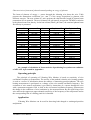
Fig. 4. VWM005 Sensor in Box.
______________________________________________________________________________
VWM005 User's Manual
4
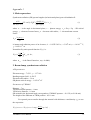
Characteristics of measured photon beams depending on energy of photons
The beam of photons of energy ! passes through the vibrating wire heats the wire. Table
presents the attenuation coefficients (µen, mm-1) of the energy deposition by photons with
different energies. The next column (lp, mm) presents the characteristic length of photon beam
penetration in wire material. The next columns (ΔP, ph/s/mm2) presents the VWM005 resolution
to the photon beam flux density. In the last column (MaxP, ph/s/mm2) the maximal photon beam
flux density is presented.
! , eV
µen, mm-1
lp, mm
ΔP, ph/s/mm2
MaxP, ph/s/mm2
1.0E+03
1.5E+03
2.0E+03
3.0E+03
4.0E+03
5.0E+03
6.0E+03
8.0E+03
1.0E+04
1.5E+04
2.0E+04
3.0E+04
4.0E+04
5.0E+04
6.0E+04
8.0E+04
1.0E+05
1.5E+05
2.0E+05
6927.962
2627.055
1257.085
468.45
215.833
117.2412
119.4314
164.5284
106.3914
37.96044
17.50937
5.923028
2.613364
1.369343
0.804036
0.348132
0.185283
0.067331
0.040174
0
0
0
1.05E-16
4.35E-08
1.00E-04
8.44E-05
2.44E-06
0.000235
0.050721
0.252793
0.628014
0.814441
0.898033
0.938804
0.973028
0.985553
0.994726
0.99685
7.8E+09
5.2E+09
3.9E+09
2.6E+09
1.95E+09
1.56E+09
1.3E+09
9.75E+08
7.8E+08
5.48E+08
5.22E+08
6.99E+08
1.05E+09
1.53E+09
2.13E+09
3.62E+09
5.4E+09
9.86E+09
1.24E+10
7.8E+14
5.2E+14
3.9E+14
2.6E+14
1.95E+14
1.56E+14
1.3E+14
9.75E+13
7.8E+13
5.48E+13
5.22E+13
6.99E+13
1.05E+14
1.53E+14
2.13E+14
3.62E+14
5.4E+14
9.86E+14
1.24E+15
An example of calculation of characteristics of positioning for synchrotron radiation
of APS ANL is presented in Appendix 1.
Operating principle
The principle of operating of Vibrating Wire Monitor is based on sensitivity of wire
oscillations frequency to temperature. The novelty of the method is that the wire heating quantity
is used as a source of information about the number of interacting particles/photons. The wire
heating measurement is performed as a change of the wire natural oscillation frequency. The
excitation of wire natural oscillations is provided by interaction of a current through the wire
with a permanent magnetic field. A shift in the wire natural oscillation frequency characterizes
the change in the conditions of wire irradiation by the measured beam. By the rigid fixing of the
wire ends on the support an unprecedented sensitivity of the frequency to the temperature and to
the corresponding flux of colliding particles is obtained.
Application
Vibrating Wire Monitor can be used for detecting both charged or uncharged particles
and photons.
______________________________________________________________________________
VWM005 User's Manual
5
Technical details
Installation drawing
The main view of the VWM005 fixed on the flange of synchrotron radiation beam dump
is presented at Fig. 5. VWM005 can be tilted at necessary angle.
Fig. 5. Main view of VWM005 mounting on the flange. Parts: 1 – VWM005, 2 – VWM005
support, 3 – beam dump tube, 4 – beam dump flange, 5 – VWM005 mounting plates, 6 – clamp
bolt, 7 – rectangular window for synchrotron beam accept with VWM005 aperture.
VWM support serve also as a screen to cut unwanted synchrotron radiation that heat VWM005
housing and un-exposed portion of the wires (see. Fig. 6). Synchrotron radiation passes through
the rectangular window 5 accept the VWM005 working aperture. Holes 4 are provided for
VWM005 support mounting on the flange (sizes must be defined).
______________________________________________________________________________
VWM005 User's Manual
6
Fig. 6. View of the VWM005 support back side. Parts: 1 – VWM005 turned at 450 around
central wire, 2 – VWM005 support, 3 – photon beam, 4 – rectangular window for synchrotron
beam accept with VWM005 aperture.
At Fig. 7. some dimensions of the VWM005 are persented.
Fig. 7. Some dimensions of the VWM005.
The dimensions of the VWM005 support are presented at Fig. 8.
______________________________________________________________________________
VWM005 User's Manual
7
Fig. 8. VWM005 support optional dimensions.
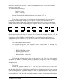
Electronics, Data Format and Test Program
Connections and Protocol
Fig. 9. Electronic unit inside wiring.
There are 5 Stringen V3.1(APS) plates inside the electronic unit (one for each vibrating
wire). The plates measure the wires oscillation frequency and transfer in RS422 standard. If the
______________________________________________________________________________
VWM005 User's Manual
8
data will be transferred to the PC (e.g. if the test program Stringener5 is used) RS232/RS422
converter is to be used.
The communication protocol is:
BaudRate = 9600 bits/s
Data bits = 8 bits
Parity = No parity
Stop bits = 1 stop bit
Scheme of connections inside the electronic unit is shown in Fig. 9.
Data Format
If the sensor is connected to the electronic unit after the electronic unit switch on the
plates begin to transfer data. Sampling rate is 1000 ms. The data from different wires are
transferred with about 150 ms shift. Number of bytes for each wire is 5: first byte is the plate
number, bytes 2 to 5 are the corresponding wire frequency in kHz in Microchip 32-bit floating
point format.
Byte No.
Description
Bits
1
Plate number
nnnn nnnn
2
3
4
5
Frequency in kHz, Microchip 32-bit floating point format
eeee eeee
s.xxx xxxx
xxxx xxxx
xxxx xxxx
Plate numbers are 1 to 5 (hexidecimal 0x01 to 0x05) for electronic unit 1 and 6 to 10 for unit 2
(hexidecimal 0x06 to 0x0A). Byte 2 - 'eeeeeeee' - is the biased 8-bit exponent with bias = 127. In
byte 2 's' is the sign bit (0 if positive and 1 if negative), '.' is the radix point. Bytes 3, 4 and 5
constitute the fraction with the most significant byte 3 with implicit most significant bit = 1.
About Microchip FP32 format see, e.g. http://www.e-sonic.com/whatsnew/Microchip/control/
AN575.pdf.
TEST PROGRAM STRINGENER5
Test program Stringener5 reads frequencies from Stringen plates (if vibrating wire
resonators are connected to plates), visualized them and saves in file.
Minimal system requirements
IBM PC 300 MHz or higher
Windows 98SE or higher
3MB on HDD for the program
additional space for data files.
Installation
To install the program double click on the setup.exe and follow the setup program
instructions. By default it is installed in folder Program Files\Stringener5. It can be changed at
installation. In any case all data files will be saved in the same directory were the file
Stringener.exe is.
Functioning
To start the program connect the PC serial port with electronic unit via RS232/422
convertor, set the correct serial port number and press the Start button. After start each second
the data from all devices are obtained and visualized in two forms: numerical list boxes (one for
each wire) and graphical. In graphical window the data are plotted on two axes. Drop-down lists
above the graphical axes contain list of devices and data of selected devices are plotted on
corresponding axis. Left and right axes can be separately zoomed in/out and moved up/down.
______________________________________________________________________________
VWM005 User's Manual
9
The data are saved in a file. To avoid large files not all data can be saved using the text box Step.
Also the data can be averaged before the saving.
______________________________________________________________________________
VWM005 User's Manual
10
Appendix 1
1. Main expressions
Synchrotron radiation (SR) spectral angular (in horizontal plane) power distribution P:
d 2P
"[m]I [ A]
[W / rad ] = P0 [W ]
$ (! / ! C ) ,
d# % d (! / ! C )
c[m / s ]e[C ]
(1)
where ! - is the angle in horizontal plane, ! - photon energy, # C = 3hc" 2 / 2 ! - SR critical
energy, ! - electrons Lorentz factor, ! - electrons orbit radius, I - electron beam current.
Factor
2r0 mc 3" 4
P0 =
3! 2
(2)
is instant total radiation power of an electron, h = 1.055E-34 J*s, c =3*108 m/s, e =1.6*10-19 C,
r0 =2.82*10-15 m.
Normalized by unit spectral function ! ( y ) is:
$
9 3
" ( y) =
y K 5 / 3 ( x) ! dx ,
8% #y
(3)
where K 5 / 3 - is the Bessel function ( ! (1) =0.4040).
2. Beam dump, synchrotron radiation
APS parameters
Electron energy – 7 GeV, ! = 1.37*104
Bending magnet field – 0.599 T
Electrons orbit radius - 39 m
SR photon critical energy – 1.95*104 eV
Parameters of VWM005
Distance – 7 m
VWM horizontal aperture – 8 mm
VWM wire diameter - 0.1 mm
SR emitted in the horizontal angle corresponds to VWM005 aperture – 99.1 W (at I=100 mA)
The height of the SR beam at VWM position - 0.511 mm
For spectral power transfer through the material with thickness d and density ! d we use
the expression:
$ ( y )TRANSFER = $ ( y ) INCIDNT * exp(#
µ (" )
* !d * d ) ,
!d
______________________________________________________________________________
VWM005 User's Manual
11
where µ (" ) / ! d - mass attenuation coefficient.
For spectral power deposited into the vibrating wire we use expression
$ ( y ) DEPOSTED = $ ( y ) INCIDNT * (1 # exp(#
µ EN (" )
* ! d * d )) ,
!d
where µ EN (" ) / ! d - mass energy-absorption coefficient.
Used spectral parameters for synchrotron radiation beam attenuation in 6 mm Cu and
deposited into the wire are [NIST]:
ε, eV
1.00E+03
1.50E+03
2.00E+03
3.00E+03
4.00E+03
5.00E+03
6.00E+03
8.00E+03
1.00E+04
1.50E+04
1.95E+04
3.00E+04
4.00E+04
5.00E+04
6.00E+04
8.00E+04
1.00E+05
1.50E+05
2.00E+05
3.00E+05
4.00E+05
5.00E+05
2
µ/ρ Cu, cm /g
1.06E+04
4.42E+03
2.15E+03
7.49E+02
3.47E+02
1.90E+02
1.16E+02
5.26E+01
2.16E+02
7.41E+01
3.38E+01
1.09E+01
4.86E+00
2.61E+00
1.59E+00
7.63E-01
4.58E-01
2.22E-01
1.56E-01
1.12E-01
9.41E-02
8.36E-02
2
µ/ρ Wire, cm /g
8.70E+03
3.30E+03
1.58E+03
5.89E+02
2.71E+02
1.47E+02
1.50E+02
2.07E+02
1.34E+02
4.77E+01
2.20E+01
7.44E+00
3.28E+00
1.72E+00
1.01E+00
4.37E-01
2.33E-01
8.46E-02
5.05E-02
3.43E-02
3.07E-02
2.93E-02
Y(y)
4.04E-01
4.04E-01
4.04E-01
4.04E-01
4.04E-01
4.04E-01
4.04E-01
4.04E-01
4.04E-01
4.04E-01
4.04E-01
3.10E-01
1.96E-01
1.24E-01
7.85E-02
3.09E-02
1.20E-02
1.08E-03
9.40E-05
6.66E-07
4.51E-09
2.97E-11
YCu(y)
0.00E+00
0.00E+00
0.00E+00
0.00E+00
0.00E+00
0.00E+00
0.00E+00
0.00E+00
0.00E+00
0.00E+00
0.00E+00
0.00E+00
9.54E-13
1.03E-07
1.54E-05
5.18E-04
1.03E-03
3.30E-04
4.08E-05
3.66E-07
2.72E-09
1.89E-11
YWire(y)
0.00E+00
0.00E+00
0.00E+00
0.00E+00
0.00E+00
0.00E+00
0.00E+00
0.00E+00
0.00E+00
0.00E+00
0.00E+00
0.00E+00
3.46E-14
2.06E-09
1.85E-07
2.73E-06
2.91E-06
3.40E-07
2.51E-08
1.53E-10
1.02E-12
6.79E-15
With ! Y ( y )dy = 1 , ! YCu ( y )dy = 4.24e " 3 , ! YWire ( y )dy = 1.14e " 5 .
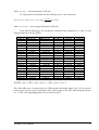
The whole SR power P0 emitted into the VWM aperture horizontal angle is 99.1 W (at electron
beam current 100 mA). Power attenuation after 6 mm copper is 420 mW, while dissipated power
is 1.13 mW. Corresponding graphics are presented in Fig. 1.
______________________________________________________________________________
VWM005 User's Manual
12
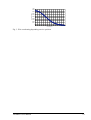
1.00E+00
Palfa=99.1 W
1.00E-01
Int=1
Spectral formfactor
1.00E-02
1.00E-03
Int=4.24E-3
1.00E-04
Int=2.67E-5
1.00E-05
Y(y)
Y_Cu(y)
Deposited in Wire(y)
1.00E-06
1.00E-07
1.00E-08
1.00E-09
1.00E-10
1.00E-11
1.00E-12
0.00E+00
1.00E+05
2.00E+05
3.00E+05
4.00E+05
5.00E+05
6.00E+05
Photon Energy, eV
Fig. 1. Power attenuation of 99.1 W synchrotron radiation after 6 mm copper is 420 mW, and
power dissipated into the wire is 1.13 mW.
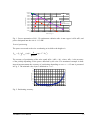
Vertical positioning
The power converted to the wire overheating at its shift to the height z is
PWire = P0 * $ Y
Dep
d
exp(# z 2 / 2! Z2 )
2" ! Z
( y )dy *
The accuracy of positioning of the wire equals !PWire /(dPWire / dz ) , where !PWire is the accuracy
of the pickup depending on the power absorbed by the wire. For mentioned example in hour
interval measurements the accuracy of positioning depending on z at ! Z = 0.5 mm is presented
in Fig. 2. The minimal value 9 µm is obtained at z " ! Z .
0.2
0.18
Positioning accuracy, mm
0.16
0.14
0.12
0.1
0.08
0.06
0.04
0.02
0
0
0.1
0.2
0.3
0.4
0.5
0.6
0.7
0.8
0.9
1
1.1
1.2
1.3
1.4
1.5
Vertical offste, mm
Fig. 2. Positioning accuracy.
______________________________________________________________________________
VWM005 User's Manual
13
0.0001
0.00009
Wire overheat power
0.00008
0.00007
0.00006
0.00005
0.00004
0.00003
0.00002
0.00001
0
0
0.1
0.2
0.3
0.4
0.5
0.6
0.7
0.8
0.9
1
1.1
1.2
1.3
1.4
1.5
Vertical offste, mm
Fig. 3. Wire overheating depending on wire position.
______________________________________________________________________________
VWM005 User's Manual
14