1
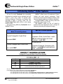
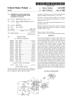
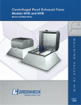
Technical Guide Form UTG-0204
Continental Chillers LLC
Phone: 317-337-9813 Fax: 317-337-9816
www.continentalchillers.com
™
UniPac
Single Phase
Air Cooled Chillers
Water Cooled Chillers
Split System Chillers
3 through 60 HP
Shown, model USAC-8
Packaged Air Cooled Chiller with
Factory Mounted Chiller Pump
Typical Scroll
Compressor
UniPac™
Continental Single Phase Chillers
Introducing UniPac™ Chiller Systems
All over the world, Continental has successfully
developed and marketed various packaged and split
chillers to serve many needs. For several years
discerning Engineers, Contractors, and Owners have
expressed a desire to specify, install and own
Unique Single Phase quality chillers in sizes ranging
from 3 to 60 HP.
This need is being fulfilled by Continental’s line of
UniPac™ Chillers.
UniPac™ chillers have a full compliment of factory
installed and wired optional accessories. These
accessories can save several hundreds of dollars in field
labor and material, resulting in cost effective installation.
Packaged UniPac™ chillers are factory tested and
shipped with a vapor charge of R-22.
Split UniPac™ chillers are “dry run” tested for
functional tests and shipped with dry air or nitrogen for
field piping evacuating and refrigerant charging.
Packaged Air Cooled and
Water Cooled Systems
Split Air Cooled Systems
To order Split (A)
To order Packaged Air Cooled Chiller:
Compressor, Chiller, Control Panel – model
USC with matching Outdoor Air Cooled
Condenser – model CAD
To order Split (B)
Use model USAC
To order Packaged Water Cooled Chiller:
Use model USWC
Compressor/Condenser (Condensing Unit)
Outdoor – model USA with matching Indoor
Chiller – model CDX
UNIPAC™ NOMENCLATURE
Packaged Air Cooled and Water Cooled Chiller Systems
U S AC or WC – X
U
S
AC
WC
X
Unique
Scroll
Condenser – Air Cooled
Condenser – Water Cooled
Nominal Horse Power 3, 4*, 5, 8*,10,12*,15, 20, 25, 30, 40, 50, 60
*For 4, 8, 12 Ton Ratings, Contact Factory
Ordering Examples: 40 ton packaged Single Phase Air Cooled Chiller, model USAC-40
30 ton packaged Single Phase Water Cooled Chiller, model USWC-30
20 ton split Single Phase Air Cooled Chiller, option A, models USC-20 (indoor compressor/chiller) and CAD-20 (outdoor A/C condenser)
20 ton split Single Phase Air Cooled Chiller, option B, models USA-20 (outdoor condensing unit) and CDX-20 (indoor chiller)
2
Phone: 317-337-9813
Fax: 317-337-9816
www.continentalchillers.com
UniPac™
Continental Single Phase Chillers
Standard Unit Specifications of UniPac™ Single Phase Chillers
General Description
Continental’s Single Phase Air and Water Cooled Chillers
are packaged systems complete with scroll compressor(s), air
cooled
or
water
cooled
condenser(s),
individual
cooler/evaporator(s), independent refrigerant circuit(s) and a control
center all mounted on a heavy duty structural steel frame.
• Sight glass/ moisture indicator
• Suction line fully insulated, designed for proper oil return at
minimum friction loss
• Discharge line formed of clean ACR type tubing and pre-formed
radius fitting
Scroll Compressor(s)
Control Center
Compressors are well proven state-of-the-art scrolls with fewer
moving parts, less rotating mass, and less internal friction than
traditional reciprocating compressors.
Motor is suction gas-cooled, hermetically sealed, two pole,
squirrel cage induction type and is directly driven at 3600 rpm.
All compressor(s) are mounted on resilient pads to minimize
vibration.
Air Cooled Condenser for Air Cooled Models
Condenser Coil-industrial quality, seamless copper tube
Fins-all aluminum, die formed with full self–spacing collars that
completely cover the copper tube; fins are mechanically bonded to
the copper tubes
Propeller Fans-large surface, low speed, low sound level propeller
fans for vertical airflow; fans are statically and dynamically balanced
and operate at low tip speeds for low vibration and sound levels
Fan Guards- PVC coated for long life
Fan Venturi- high collar fully spun venturi design for high efficiency
and low outlet noise
Fan Motors-special “enclosed air over” motor design with built-in
overload protection; single phase motors operate at a low speed of
1075 rpm
Water Cooled Condenser for Water Cooled Models
Each water cooled condenser is of shell/coil design. The
condenser water flows through special heat transfer copper tube.
Refrigerant flows through the steel shell and a built in receiver.
Cooler/Evaporator for All Models
Each cooler/evaporator is of shell/coil design. The water to be
chilled flows through special heat transfer copper tube. Refrigerant
flows through the steel shell/receiver.
Refrigerant Piping
Each Refrigerant circuit includes:
• Liquid line with charging connection
• Filter drier
• Liquid solenoid valve with 115 V coil (220 V or 24 V, optional)
All power, starting, safety and operating controls are mounted in
a built in fully enclosed, weather proof control panel for air cooled
models and NEMA-1 enclosures for indoor water cooled or
condenserless models.
Power controls include:
• Single point electrical terminal block for 230/1/60 power input
• Compressor-motor contactor(s)
• Compressor run capacitor(s)
• Fan motor contactor(s) (air cooled units only)
• Control circuit fuse
• Control circuit terminal block
Safety/Operating controls include:
•
•
•
•
•
•
•
•
Two position switch indicating off/system on – per circuit
High Pressure control with manual reset –per circuit
Low pressure control with auto reset – per circuit
Adjustable chilled water temperature controller
Adjustable freezestat
Adjustable compressor anti-recycle timer(s)
Relay(s)
Built-in compressor-motor overload
Testing, Evacuation and Refrigerant Charging
Each completed system is pressure tested with nitrogen,
evacuated with a high capacity vacuum pump, vapor charged with
R-22 and fully tested for all operating and safety controls. Field
charge of R-22 required.
Split chiller systems are “dry run” tested for operating and
safety controls.
Assembly
All above components are assembled on a heavy-duty
structural steel frame, formed of channels and angles as a rugged
pre-engineered package. Each steel frame has mounting holes and
“lifting eyes” on four sides for “spreader bar” lifting and rigging.
The cabinet of air cooled units is made of heavy gauge
galvanized steel.
3
Phone: 317-337-9813
Fax: 317-337-9816
www.continentalchillers.com
UniPac™
Continental Single Phase Chillers
UniPac™ Options and Selection Procedures
1.
14. Copper Tube/Copper Fin Condenser Coil - Seamless copper tube with die
formed copper fins, mechanically bonded to the tube. Provides maximum protection
from salt-water environment due to the elimination of dissimilar metals.
15. Complete Unit Coating - Your choice of paint, Blygold, Imron, polyester or
Heresite coating for compete unit.
16. Stainless Steel Hardware - For extra protection against corrosion.
17. Low Speed Condenser Fan Motors - For lower noise levels
18. Centrifugal Condenser Fans - For ducted applications
19. Acoustical Enclosure - Compressor is located in an acoustical enclosure
providing dampening of sound levels.
20. Dual Unit Kit - Allows operation of two or more units
21. Alarm Bell Contacts - Allows alarm bell connection to pressure controls for
signaling if unit fails on manual reset safety controls. (alarm bell is not included but
can be provided)
22. Water Flange Kit - Factory or field mounted consists of 150lb raised face
flanges to convert male pipe thread to flanged cooler connections.
23. High Return Water Thermostat - Factory mounted thermostat senses high
return water temperature at start-up. Allows unit to run un-loaded instead of shutting
down due to high head pressure
24. Brine Chilling - Modified cooler and controls for various
brines/glycols/alcohols.
25. High entering Water Process Cooling - Secondary plate heat exchanger
with pump, factory mounted and wired to protect compressor against burnouts due to
high water temperatures.
26. Potable/Ingredient Water at 34°F - For bakeries/produce or other
applications.
27. Cooler Heater with Thermostat - For freeze protection.
28. Desuperheaters - Provides “free hot water” by recovering heat from super
heated gas.
29. Compressor Circuit Breaker - Both fused and non-fused short circuit
protection for each compressor, further reducing chance of motor burnout.
30. Digital Temperature Readout
31. Compressor Cycle Counter/Hour Meters
32. Non-Ozone Depleting, Environmentally-Friendly Refrigerant
Control Transformer - For applications where a separate 115-volt power
source is not available, a transformer can be installed and wired between the line
voltage power terminal block and the 115-volt control circuit. Transformer primary
fuses are included.
2. Factory mounted and wired flow switch - This accessory is mandatory for
Continental warranty to be effective. Provides protection from chiller freezing due to
“no flow” through chiller-evaporator.
3. Factory Mounted and Wired Chiller Water Pump/Valve - Includes chilled
water circulating pump, pump starter, and isolation valve. Provides system pump for
chilled water circulation- saves field labor and material. This pump is interlocked with
the flow switch and “phased in” at the factory for proper rotation.
4. Non-fused Disconnect - Factory mounted non-fused disconnect sized for
model and voltage. This saves field labor and material.
5. Low Evaporator Pressure Freezestat - Senses low evaporator pressure and
shuts down system after sixty second time delay. Extra safety protection against low
pressure due to gas shortage or freeze conditions.
6. Pressure Gauges - Two-inch diameter gauges are factory installed and piped
to compressor. High and low pressure for each refrigerant circuit.
7. Indicator Lights - Three indicating lights show Power On, High Pressure Fail,
and No Flow/Freeze for each refrigerant circuit.
8. Vibration Isolators - Level adjusting spring type for one-inch deflection for
field mounting-reduces vibration transmission.
9. Low Ambient Controls - Standard units have fan cycling and are good for
45°F ambient.
a) For Low Ambient of 0°F. Includes a modulating solid state fan speed controller
and a single phase condenser motor(s) as well as fan cycling.
b) For Low Ambient of –20°F. Includes head pressure control valve in conjunction
with oversized heated and insulated receiver(s) and fan cycling. Receiver includes
pressure relief valve.
10. Micro-Processor Controller
11. Water Regulating Valve - Provides head pressure control for water cooled
models USWC.
12. 90/10 Cu-Ni Condenser - For water cooled models, USWC.
13. Blygold or Heresite Coated Condenser - Coil is coated with Blygold or
Heresite for protection against elements. Minimal effect on heat transfer.
Ratings and Selection Procedures
1.
Ratings: are in accordance with ARI standard for chillers. These ratings
may be interpolated for any published chilled water temperatures between 40°F
and 50°F but must not be extrapolated.
2. Chilled Water Flow: based on 2.4 GPM per Ton and 10°F chilled water
range. Limit 6°F minimum to 14°F maximum.
3. Cooler Fouling Factor: 0.00025 fouling is standard
For 0.0005 fouling capacity correction factor = 0.982 x TR, 0.994 x kW
For 0.00075 fouling capacity correction factor = 0.964 x TR, 0.989 x kW
4. Water cooled condenser fouling factor : ratings are based on 0.00025 for
condenser. For 0.00075 Condenser tons x 0.97 –kW x 1.045
5. Copper Fin Ratings: TR x 1.01 – kW x 0.99
6. Ethylene Glycol Correction Factors: Following factors are to be applied
to the standard ratings for ethylene glycol. For other glycols consult factory.
Correction Factors
Freeze
% Wt.
Point
Ethylene
GPM/
(°F)
Glycol
Tons
kW
VP
°F /Ton
10
.995
1.000
1.02
24.1
26
20
.990
0.995
1.05
24.8
16
30
.980
.990
1.10
26.0
5
40
.975
0.985
1.13
27.3
-10
50
.960
0.980
1.18
29.0
-32
Altitude: Ratings are based on altitude of sea level. For other ratings use the following
correction factors
Alt. Above
Capacity
Alt. Above
Capacity
Sea Level
Multiplier
Sea Level
Multiplier
Sea Level
1.0
4000
.971
1000
1.0
5000
.962
2000
.995
6000
.951
3000
.980
7000
.949
7. For ratings outside this catalog range consult Continental for assistance
Tel:(317)337-9813 Fax:(317)337-9816
E-mail: [email protected]
Selection Procedures
All units are rated in accordance with ARI Standard and cover a wide range of leaving
chilled water temperatures and ambients from 85°F to 120°F.
To select any chiller it is necessary to know:
1. Capacity: ______ Tons
2. Entering and leaving chilled water temperature: ______ °F
3. Water Flow: ______ GPM
4. Design ambient temperature: ______ °F or
5. Entering/leaving cond. water temperature, for water cooled units: ______ °F
Knowing any two of items 1,2 or 3, the third can be calculated as follows:
GPM = Tons x 24
Temp. Rise(Vt)
4
Phone: 317-337-9813
Fax: 317-337-9816
www.continentalchillers.com
UniPac™
Continental Single Phase Chillers
Single Phase Air Cooled Ratings
Models USAC-3 through USAC-20
3 through 20 Tons
Ambient Air Temperature °F
LCWT
°F
40
42
44
45
46
48
50
Model
USAC
85
95
Cooler
GPM
TR
105
kW
Cooler
GPM
TR
115
kW
Cooler
GPM
TR
120
kW
Cooler
GPM
TR
kW
Cooler
GPM
TR
kW
3
2.6
3.0
6.2
2.3
3.1
5.5
2.1
3.2
5.0
1.8
3.3
4.3
1.6
3.3
3.8
5
4.3
5.0
10.3
3.9
5.2
9.4
3.5
5.4
8.4
3.0
5.5
7.2
2.8
5.8
6.7
10
8.6
10.0
20.6
7.8
10.4
18.7
7.0
10.8
16.8
6.0
11.0
14.4
5.6
11.6
13.4
15
13.0
15.0
31.2
11.7
15.6
28.1
10.5
16.2
25.2
9.0
16.5
21.6
8.4
9.9
20.2
20
17.2
20.0
41.3
15.2
20.8
36.5
14.0
21.6
33.6
12.0
22.0
28.8
11.2
23.2
26.9
3
2.9
3.0
7.0
2.5
3.2
6.0
2.2
3.2
5.3
2.0
3.4
4.8
1.8
3.4
4.3
5
4.6
5.1
11.0
4.1
5.3
9.8
3.7
5.5
8.9
3.3
5.7
7.9
3.0
5.8
7.2
10
9.2
10.2
22.1
8.2
10.6
19.7
7.4
11.0
17.8
6.6
13.7
15.8
6.0
11.6
14.4
15
13.8
15.3
33.1
12.3
15.9
29.5
11.1
16.5
26.6
9.9
17.1
23.8
9.0
17.4
21.6
20
18.4
20.4
44.2
16.4
21.2
39.4
14.8
22.0
35.5
13.2
27.4
31.7
12.0
23.2
28.8
3
3.1
3.1
7.4
2.8
3.3
6.7
2.4
3.4
5.8
2.1
3.5
5.0
1.9
3.5
4.6
5
4.9
5.2
11.8
4.4
5.4
10.6
4.0
5.7
9.6
3.5
5.9
8.4
3.2
5.9
7.7
10
9.8
10.4
23.5
8.8
10.8
21.1
8.0
11.4
19.2
7.0
11.8
16.8
6.4
11.8
15.4
15
14.7
15.6
35.3
13.2
16.2
31.7
11.1
16.5
26.6
10.5
17.7
25.2
9.6
17.7
23.0
20
19.6
20.8
47.0
17.6
21.6
42.2
16.0
22.8
38.4
14.0
23.6
33.6
12.8
23.6
30.7
3
3.2
3.1
7.6
2.9
3.3
6.8
2.5
3.5
6.0
2.1
3.6
5.0
2.0
3.6
4.7
5
5.0
5.2
11.9
4.5
5.5
10.8
4.1
5.8
9.8
3.6
6.0
8.6
3.3
6.0
7.9
10
9.9
10.4
23.8
9.0
10.9
21.6
8.2
11.5
19.7
7.3
11.9
17.5
6.6
12.0
15.8
15
14.8
15.6
35.5
13.3
16.4
31.9
11.8
17.0
28.3
10.8
17.8
25.9
9.9
18.0
23.8
20
19.9
20.8
47.8
18.0
21.8
43.2
11.9
20.1
28.6
14.4
23.8
34.6
13.2
24.0
31.7
3
3.2
3.1
7.7
2.9
3.3
7.0
2.6
3.5
6.2
2.2
3.6
5.3
2.0
3.6
4.8
5
5.0
5.2
12.0
4.6
5.5
11.0
4.2
5.8
10.1
3.7
6.0
8.9
3.4
6.1
8.2
10
10.0
10.4
24.0
9.2
11.0
22.1
8.4
11.6
20.2
7.4
12.0
17.8
6.8
12.2
16.3
15
15.0
15.6
36.0
13.4
16.5
32.2
12.6
17.4
30.2
11.1
18.0
26.6
10.2
18.3
24.5
20
20.0
20.8
48.0
18.4
22.0
44.2
16.8
23.2
40.3
14.8
24.0
35.5
13.6
24.4
32.6
3
3.4
3.2
8.2
3.0
3.4
7.2
2.7
3.5
6.5
2.4
3.7
5.8
2.2
3.7
5.3
5
5.2
5.3
12.5
4.8
5.6
11.5
4.3
5.9
10.3
3.9
6.1
9.4
3.6
6.2
8.6
10
10.4
10.6
25.0
9.6
11.2
23.0
8.6
11.8
20.6
7.8
12.2
18.7
7.2
12.4
17.3
15
15.6
15.9
37.4
14.4
16.8
34.6
12.9
17.7
31.0
11.7
18.3
28.1
10.8
18.6
25.9
20
20.8
21.7
49.9
19.2
22.4
46.1
17.2
23.6
41.3
15.6
37.6
37.4
21.6
37.2
51.8
3
3.5
3.2
8.4
3.2
3.4
7.7
2.8
3.6
6.7
2.5
3.7
6.0
2.3
3.8
5.5
5
5.4
5.4
13.0
5.0
5.7
12.0
4.5
6.0
10.8
4.1
6.2
9.8
3.8
6.3
9.1
10
10.8
10.8
25.9
10.0
11.4
24.0
9.0
12.0
21.6
8.2
12.4
19.7
7.6
12.6
18.2
15
16.2
16.2
38.9
15.0
17.1
36.0
13.5
18.0
32.4
12.3
18.6
29.5
11.4
18.9
27.4
21.6
21.6
51.8
20.0
22.8
48.0
18.0
24.0
43.2
16.4
24.8
39.4
15.2
25.2
36.5
20
LCWT:
Leaving chilled water temperature, °F
TR:
Tons of refrigeration cooling capacity
kW:
Cooler GPM:
Compressor power input
Flow rate in US GPM for cooler
5
Phone: 317-337-9813
Fax: 317-337-9816
www.continentalchillers.com
UniPac™
Continental Single Phase Chillers
Single Phase Air Cooled Ratings
Models USAC-25 through USAC-60
25 through 60 Tons
Ambient Air Temperature °F
LCWT
°F
40
42
44
45
46
48
50
Model
USAC
85
95
105
115
120
TR
kW
Cooler
GPM
TR
kW
Cooler
GPM
TR
kW
Cooler
GPM
TR
kW
Cooler
GPM
TR
kW
Cooler
GPM
25
21.5
25.0
51.6
19.5
26.0
46.8
17.5
27.0
42.0
15.0
27.5
36.0
14.0
29.0
33.6
30
25.8
30.0
61.9
23.4
31.2
56.2
21.0
32.4
50.4
18.0
33.0
43.2
17.0
35.0
40.8
40
34.4
40.0
82.6
31.2
41.6
74.9
28.0
43.0
67.2
24.0
44.0
57.6
22.4
46.4
53.8
50
13.0
50.0
31.2
39.0
52.0
93.6
35.0
54.0
84.0
30.0
55.0
72.0
28.0
58.0
67.2
60
51.6
60.0
123.8
47.0
63.0
112.8
42.0
65.0
100.8
36.0
66.0
86.4
33.6
69.6
80.6
25
23.0
25.5
55.2
20.5
26.5
49.2
18.5
27.5
44.4
16.5
28.5
39.6
15.0
29.0
36.0
30
28.0
31.0
67.2
25.0
32.0
60.0
22.0
33.0
52.8
20.0
34.0
48.0
18.0
35.0
43.2
40
37.0
41.0
88.8
33.0
43.0
79.2
30.0
44.0
72.0
26.4
45.6
63.4
24.0
30.0
57.6
50
46.0
51.0
110.4
41.0
53.0
98.4
37.0
55.0
88.8
33.0
57.0
79.2
30.0
58.0
72.0
60
55.0
61.0
132.0
49.0
63.6
117.6
44.0
66.0
105.6
39.6
68.4
95.0
36.0
69.6
86.4
25
24.5
26.0
58.8
22.0
27.0
52.8
20.0
38.5
48.0
17.5
29.5
42.0
16.0
29.5
38.4
30
29.4
31.2
70.6
26.4
32.4
63.4
24.0
34.2
57.6
21.0
35.4
50.4
19.2
35.4
46.1
40
39.0
41.6
93.6
35.0
43.0
84.0
32.0
46.0
76.8
28.0
47.0
67.2
26.0
47.0
62.4
50
49.0
52.0
117.6
44.0
54.0
105.6
40.0
57.0
96.0
35.0
59.0
84.0
32.0
59.0
76.8
60
59.0
62.4
141.6
53.0
65.0
127.2
48.0
68.4
115.2
42.0
71.0
100.8
38.4
71.0
92.2
25
24.7
26.0
59.3
22.5
27.3
54.0
20.5
28.7
49.2
18.0
29.7
43.2
16.5
30.3
39.6
30
29.7
31.2
71.3
27.2
32.7
65.3
24.5
34.6
58.8
21.5
35.7
51.6
19.6
36.2
47.0
40
39.5
41.6
94.8
36.0
43.5
86.4
33.0
46.1
79.2
29.0
47.5
69.6
26.5
48.0
63.6
50
49.5
52.0
118.8
45.0
54.5
108.0
41.0
57.5
98.4
36.0
59.5
86.4
33.0
60.0
79.2
60
59.5
62.4
142.8
54.1
65.5
129.8
49.2
69.0
118.1
43.2
71.5
103.7
39.7
72.1
95.3
25
25.0
26.0
60.0
23.0
27.5
55.2
21.0
29.0
50.4
18.5
30.0
44.4
17.0
31.0
40.8
30
30.0
31.2
72.0
28.0
33.0
67.2
25.0
35.0
60.0
22.0
36.0
52.8
20.0
37.0
48.0
40
40.0
41.6
96.0
37.0
44.0
88.8
34.0
46.0
81.6
30.0
48.0
72.0
27.0
49.0
64.8
50
50.0
52.0
120.0
46.0
55.0
110.4
42.0
58.0
100.8
37.0
60.0
88.8
34.0
61.0
81.6
60
60.0
62.4
144.0
55.2
66.0
132.5
50.4
69.6
121.0
44.4
72.0
106.6
41.0
73.2
98.4
25
26.0
26.5
62.4
24.0
28.0
57.6
21.5
29.5
51.6
19.5
30.5
46.8
18.0
31.0
43.2
30
31.0
32.0
74.4
29.0
34.0
69.6
26.0
35.4
62.4
23.4
36.6
56.2
21.6
37.0
51.8
40
42.0
43.0
100.8
38.0
45.0
91.2
34.4
47.2
82.6
31.2
49.0
74.9
29.0
49.6
69.6
50
52.0
53.0
124.8
48.0
56.0
115.2
43.0
59.0
103.2
39.0
61.0
93.6
36.0
62.0
86.4
60
62.4
36.6
149.8
57.6
67.2
138.2
51.6
70.8
123.8
46.8
73.2
112.3
43.2
74.4
103.7
25
27.0
27.0
64.8
25.0
28.5
60.0
22.5
30.0
54.0
20.5
31.0
49.2
19.0
32.0
45.6
30
32.4
32.4
77.8
30.0
34.0
72.0
27.0
36.0
64.8
25.0
37.0
60.0
23.0
38.0
55.2
40
43.0
43.0
103.2
40.0
46.0
96.0
36.0
48.0
86.4
33.0
50.0
79.2
30.4
50.4
73.0
50
54.0
54.0
129.6
50.0
57.0
120.0
45.0
60.0
108.0
41.0
62.0
98.4
38.0
63.0
91.2
64.8
64.8
155.5
60.0
68.4
144.0
54.0
72.0
129.6
49.2
74.4
118.1
45.6
75.6
109.4
60
LCWT:
Leaving chilled water temperature, °F
kW:
Compressor power input
TR:
Tons of refrigeration cooling capacity
Cooler GPM:
Flow rate in US GPM for cooler
6
Phone: 317-337-9813
Fax: 317-337-9816
www.continentalchillers.com
UniPac™
Continental Single Phase Chillers
Single Phase Water Cooled Ratings
Models USWC-3 through USWC-60
3 through 60 tons
Condenser Leaving Water Temperature, °F
LCWT
°F
Model
USWC
85
TR
40
44
48
kW
95
Cooler
GPM
Cond
GPM
TR
kW
100
Cooler
GPM
Cond
GPM
TR
kW
Cooler
GPM
Cond
GPM
3
3.0
3.0
7.2
9.0
2.8
3.0
6.7
8.4
2.6
3.0
6.2
7.8
5
5.0
5.0
12.0
15.0
4.7
5.0
11.3
14.1
4.3
5.0
10.3
12.9
10
10.0
10.0
24.0
30.0
9.3
10.0
22.3
27.9
8.6
10.0
20.6
25.8
15
15.0
15.0
36.0
45.0
14.0
15.0
33.6
42.0
13.0
15.0
31.2
39.0
20
20.0
20.0
48.0
60.0
18.6
20.0
44.6
55.8
17.2
20.0
41.3
51.6
25
25.0
25.0
60.0
75.0
23.3
25.0
55.9
69.9
21.5
25.0
51.6
64.5
30
30.0
30.0
72.0
90.0
27.9
30.0
67.0
83.7
25.8
30.0
61.9
77.4
40
40.0
40.0
96.0
120.0
37.2
40.0
89.3
111.6
34.4
40.0
82.6
103.2
50
50.0
50.0
120.0
150.0
46.5
50.0
111.6
139.5
43.0
50.0
103.2
129.0
60
60.0
60.0
144.0
180.0
55.8
60.0
133.9
167.4
51.6
60.0
123.8
154.8
3
3.5
3.1
8.4
10.5
3.3
3.1
7.9
9.9
3.1
3.1
7.4
9.3
5
5.4
5.2
13.0
16.2
5.2
5.2
12.5
15.6
4.9
5.2
11.8
14.7
10
10.8
10.4
25.9
32.4
10.3
10.4
24.7
30.9
9.8
10.4
23.5
29.4
15
16.2
15.6
38.9
48.6
15.5
15.6
37.2
46.5
14.7
15.6
35.3
44.1
20
21.5
20.8
51.6
64.5
20.6
20.8
49.4
61.8
19.6
20.8
47.0
58.8
25
27.0
26.0
64.8
81.0
25.8
26.0
61.9
77.4
24.5
26.0
58.8
73.5
30
32.5
31.2
78.0
97.5
31.0
31.2
74.4
93.0
29.4
31.2
70.6
88.2
40
43.2
41.6
103.7
129.6
41.1
41.6
98.6
123.3
39.0
41.6
93.6
117.0
50
54.0
52.0
129.6
162.0
51.5
52.0
123.6
154.5
49.0
52.0
117.6
147.0
60
64.5
62.4
154.8
193.5
61.8
62.4
148.3
185.4
59.0
62.4
141.6
177.0
3
4.0
3.2
9.6
12.0
3.7
3.2
8.9
11.1
3.4
3.2
8.2
10.2
5
5.8
5.3
13.9
17.4
5.5
5.3
13.2
16.5
5.2
5.3
12.5
15.6
10
11.6
10.6
27.8
34.8
13.8
10.6
33.1
41.4
10.4
10.6
25.0
31.2
15
17.4
15.9
41.8
52.2
16.5
15.9
39.6
49.5
15.6
15.9
37.4
46.8
20
23.0
21.7
55.2
69.0
21.9
21.7
52.6
65.7
20.8
21.7
49.9
62.4
25
29.0
26.5
69.6
87.0
27.5
26.5
66.0
82.5
26.0
26.5
62.4
78.0
30
35.0
32.0
84.0
105.0
33.0
32.0
79.2
99.0
31.0
32.0
74.4
93.0
40
46.4
43.0
111.4
139.2
44.2
43.0
106.1
132.6
42.0
43.0
100.8
126.0
50
58.0
53.0
139.2
174.0
55.0
53.0
132.0
165.0
52.0
53.0
124.8
156.0
60
69.0
63.6
165.6
207.0
65.7
63.6
157.7
197.1
62.4
63.6
149.8
187.2
LCWT:
TR:
Leaving chilled water temperature, °F
Tons of refrigeration cooling capacity
kW:
Cooler GPM:
Cond GPM:
Compressor power input
Flow rate in US GPM for cooler
Flow rate in US
7
Phone: 317-337-9813
Fax: 317-337-9816
www.continentalchillers.com
UniPac™
Continental Single Phase Chillers
USAC Physical Data
USAC-3, 4, 5, 8
USAC-10, 12, 15, 20
USAC-25, 30
Model USAC
-3, 4
-5, 8
-10, 12, 15, 20
-25, 30
-40
-50, 60
USAC-40, 50, 60
L”
48
48
90
120
90
120
Dimensions
W”
43
43
43
43
86
86
Weight, lbs.
H”
53
53
55
55
55
55
500/600
650/900
1,100/1,300/1,500
2,000/2,300
3,000
4,000/4,500
Water Connections
Inlet, MPT”
Outlet, MPT”
¾
1
2
3
4
4
¾
1
2
3
4
4
Est R-22
Charge, lbs.
9/11
12/18
22/25/30/40
50/60
85
110/140
8
Phone: 317-337-9813
Fax: 317-337-9816
www.continentalchillers.com
UniPac™
Continental Single Phase Chillers
USWC Physical Data
USWC-3, 5, 10
USWC-15, 20
USWC-25, 30
Dimensions
Model USWC
-3, 5
-10
-15, 20
-25, 30
Weight, lbs.
L”
W”
H”
20
20
48
84
34
34
34
34
48
48
48
48
400/500
700
900/1,000
1,200/1,600
Water Connections,
Inlet”/Outlet”
Condenser
Cooler
¾
1
1½
2
¾
1
1½
2
Est R-22
Charge, lbs.
7/14
24
40/55
65/80
For models larger than USWC-30, please contact the factory for data
9
Phone: 317-337-9813
Fax: 317-337-9816
www.continentalchillers.com
UniPac™
Continental Single Phase Chillers
Electrical Data
USAC Packaged Air Cooled Chillers
Total Unit
Compressor Motor Data
Condenser Fan Motor Data
Standard Unit
Model
MCA
Max
Fuse
Rec.
Fuse
Qty
HP
Each
RLA
Each
LRA
Each
MCC
Each
Qty
HP
Each
FLA
Each
Optional Low Ambient Unit
Single Phase/Single
Speed Motor
Qty
HP
Each
RLA
Each
Single Phase/Speed
Control
Qty
HP
Each
RLA
Each
USAC-3
30
45
35
1
3
18.4
95
25.8
1
0.75
5.3
_
_
_
1
0.75
5.3
USAC-4
33
55
40
1
4
22.1
137
31
1
0.75
5.3
_
_
_
1
0.75
5.3
USAC-5
45
77
55
1
5
32.1
148
45
1
0.75
5.3
_
_
_
1
0.75
5.3
USAC-8
55
77
60
2
4
22.1
137
31
1
0.75
5.3
_
_
_
1
0.75
5.3
USAC-10
83
115
90
2
5
32.1
148
45
2
0.75
5.3
1
0.75
5.3
1
0.75
5.3
USAC-12
83
105
88
3
4
22.1
137
31
2
0.75
5.3
1
0.75
5.6
1
0.75
5.3
USAC-15
115
150
125
3
5
32.1
148
45
2
0.75
5.3
1
0.75
5.3
1
0.75
5.3
USAC-20
150
180
160
4
5
32.1
148
45
2
0.75
5.3
1
0.75
5.3
1
0.75
5.3
USAC-25
185
215
200
5
5
32.1
148
45
2
1.5
6.6
1
1.5
6.6
1
1.5
6.6
USAC-30
220
250
230
6
5
32.1
148
45
2
1.5
6.6
1
1.5
6.6
1
1.5
6.6
USAC-40
290
325
300
8
5
32.1
148
45
4
0.75
5.3
2
0.75
5.3
2
0.75
5.3
USAC-50
350
390
370
10
5
32.1
148
45
4
1.5
6.6
2
1.5
6.6
2
1.5
6.6
USAC-60
420
450
430
12
5
32.1
148
45
4
1.5
6.6
2
1.5
6.6
2
1.5
6.6
Electrical Data
USWC Packaged Water Cooled Chillers
Model
Total Unit
MCA
Max Fuse
Compressor Motor Data
Rec. Fuse
Qty
HP Each
RLA Each
LRA Each
MCC Each
USWC-3
25
40
30
1
3
18.4
95
25.8
USWC-4
28
50
35
1
4
22.1
137
31
USWC-5
40
72
50
1
5
32.1
148
45
USWC-8
50
72
55
2
4
22.1
137
31
USWC-10
72
104
80
2
5
32.1
148
45
USWC-12
72
95
77
3
4
22.1
137
31
USWC-15
104
106
115
3
5
32.1
148
45
USWC-20
136
169
145
4
5
32.1
148
45
USWC-25
169
200
175
5
5
32.1
148
45
USWC-30
200
233
200
6
5
32.1
148
45
USWC-40
265
297
275
8
5
32.1
148
45
USWC-50
330
360
360
10
5
32.1
148
45
USWC-60
395
425
400
12
5
32.1
148
45
Notes:
1.
2.
3.
4.
5.
All units have across-the-line start.
RLA (rated load amps) rated in accordance with ARI Standard.
MCA (minimum circuit amps) equal 125% of the RLA for the largest motor in the circuit plus 100% of the RLA for all other motors in the circuit per N.E.C.
Based on copper conductors with 75° C insulation per N.E.C. Table 310-16.
Max fuse size is based on 225% of the RLA for the largest motor in the circuit plus 100% of the RLA for all other motors in the circuit per N.E.C. This is the
largest fuse allowed per N.E.C. A smaller fuse is often recommended based on the unit application and ambient temperature.
10
Phone: 317-337-9813
Fax: 317-337-9816
www.continentalchillers.com
UniPac™
Continental Single Phase Chillers
Installation and Application Data
For multiple units, a minimum lateral clearance of 10 feet between
two units is recommended.
General
4.
Continental UniPac™ Air Cooled Packaged Chillers models USAC
are designed for outdoor installations and normal exposure to summer
and winter conditions. The vertical condenser air discharge feature
allows rooftop or ground installations. Horizontal units are also available.
The enclosure door is provided to protect the electrical components
against unauthorized access. However, consideration should be given to
a field-installed protective fence to further reduce possibility of accidental
damage or unauthorized entry, especially for ground level installations.
Field installed fence must have a minimum of 50% open area.
Continental UniPac™ Water Cooled Packaged Chillers models
USWC ar designed for indoor installations and normal indoor conditions.
However, if outdoor installation is required, the factory option of a
complete unit enclosure and heater tape with thermostat for the cooler
and condenser must be ordered.
Field Piping
1. If a circulating pump is field furnished, the pump must discharge into the
cooler first and then through the cooler to the system.
2. Provide stop valves on all inlet and outlet piping to facilitate servicing.
3. Provide drain connections at low points to permit drainage of cooler and field
piping.
4. Provide air vents at high points easily accessible for servicing
5. Provide a strainer on the inlet to the cooler.
6. Provide wall hangers and rubber isolated piping hangers to reduce sound
and vibration transmission though liquid piping.
7. Provide thermometers and pressure gauges for installation in the inlet and
outlet water lines. These items are available as optional features and are not
included in the standard unit.
8. Chilled water lines should be insulated to reduce heat pick up and prevent
condensation.
9. For winter low ambient operation, it is recommended that a heater cable of 4
watts per lineal foot of pipe be installed, and exposed lines be properly insulated
to protect against freeze conditions.
10. Flush all chilled water piping prior to final connection to the UniPac™ chiller
systems.
The following guidelines are recommended:
Location for Air Cooled Systems
1. Whether it is a rooftop or ground level installation, select a place with
unrestricted fresh air supply for the air cooled condenser and minimum sun
exposure.
2. Avoid locations between structures, beneath windows, or any other restriction
that may affect adequate air supply to the condenser and where normal operating
sounds may be objectionable.
3. The condenser fans are propeller type and are not designed for use with duct
work
Water Treatment
Adequate water treatment should be determined locally, depending
on the local water quality and the type of system. Any foreign material or
dirt in the water system can adversely affect the performance of the
UniPac™ unit.
Location for Water Cooled Systems
1. The preferred location for the water cooled system is a proper plant room
with at least 4ft access on all four sides.
Freeze Protection
Foundation
Continental recommends use of a premixed glycol (Propylene or
Ethylene) or HVAC heat transfer fluids. Contact factory for more details.
Automotive antifreeze is not recommended because these often include
silicates. Silicates end up coating the heat transfer surface reducing
efficiency, fouling the system and shortening the life of the pump seals.
All chillers should be mounted on a flat and level foundation, ground,
or rooftop, capable of supporting the total operating weight of the unit
and service personnel.
(a)
Ground Level It is important that the units be installed on a
substantial base that will not settle, causing strain on the liquid lines, resulting in
possible leaks. Mounting holes (9/16”) are provided in the unit steel channels for
bolting the unit to its foundation. An independent one-piece concrete slab, not tied
to the main building and with footers extended below the frost line, is
recommended.
(b)
Roof-top Rooftop installations will require consideration by an
architect and contractor to have adequate structural strength to safely support the
entire operating weight of the unit and service personnel. Structurally transmitted
vibration and sound must be avoided by mounting the unit on proper isolators.
Corrosive Atmosphere Operation
Continental offers the following choices of condenser coil
combinations for various corrosive atmospheres.
Blygold or Heresite coating for aluminum fins; Copper Fins with
Blygold or Heresite coating or complete unit coated with Blygold, Imron
or Heresite.
Field Electric Wiring
Clearances
Air cooled systems draw air from all sides; therefore units must be
installed with sufficient clearances for air entrance to the condenser coil,
for air discharge away from the condenser, and for servicing. Minimum
clearances for all units are 4 feet on all sides.
2. In installations where winter operation is intended and snow
accumulations are expected, additional height must be provided in order
to insure normal condenser airflow.
3. When free airflow to the condenser is reduced or restricted,
condenser air may be recirculated, considerably reducing system
capacity and increasing power consumption. All ratings are based on
free air discharge.
All field wiring must be in accordance with applicable local/national
codes and ordinances
Continental chiller systems are factory wired for optimum reliability.
Controls are factory set for the operating conditions. These controls must
not be field modified without written consent from Continental; otherwise
the warranty is voided. The use of a simple remote switch or timer is
permitted but it must be connected to the Continental control panel at
points specifically indicated for that purpose.
Remote chilled water set point option is available- see under
options.
1.
Phone: 317-337-9813
Fax: 317-337-9816
11
www.continentalchillers.com
UniPac™
Continental Single Phase Chillers
UniPac™Guide Spec
Furnish and install where indicated on plans Qty______
Continental UniPac™ model (USAC, USWC) _________
packaged liquid chiller(s).
The (each) unit shall have a cooling capacity of ______ Tons
with ______ compressor kW when cooling _______GPM of water
from ______°F to _______°F and a cooler fouling factor of 0.00025
Hr. Sq. Ft °F/Btu. The water pressure drop shall not exceed
______ feet of water through the cooler. The USAC entering air
temperature will be _______°F. The USWC unit will be supplied
with ______GPM of _______°F condenser water with a condenser
fouling factor of 0.00025 Hr. Sq. Ft. °F/Btu. The condenser water
pressure drop shall not exceed _______ft of water.
The unit overall dimensions shall not exceed ______ins. In
length. _____ins in width and ______ins. In height. The unit
operating weight shall not exceed ______lbs.
General
Packaged Liquid Chiller shall be completely factory assembled
including all interconnecting refrigerant piping and internal wiring
controls, mounted on a steel frame which accommodates the air
(water) cooled condenser, compressor and cooler. The units shall
be leak tested, evacuated and shipped with a vapor charge of R-22.
Split chillers shall be field piped, pressure tested, evacuated
and then field charged with R-22.
All units shall include the following:
Compressor Motor
USAC/USWC compressor motor shall be state-of-the-art scroll
with fewer moving parts and sweated without valves. All
compressor(s) shall be mounted on resilient pads to minimize
vibration. Safety internal relief per ASA-B9.1 Code.
Cooler
The cooler shall be direct expansion shell and coil type with
refrigerant in the shell and liquid to be chilled in the tube. The
design working pressure of the cooler shell (liquid) side shall be
150 psig. And 200 psig for the tube (refrigerant) side. The cooler
shall be insulated with ¾” closed cell insulation.
Condenser-Air Cooled
The condenser shall be of copper tube, aluminum fin
construction. Fans shall be propeller-type direct driven by totally
enclosed “air over” motors with built-in overload protection,
positioned within the cabinets for weather protection.
Condenser – Water Cooled
The condenser shall be shell and coil type with water flowing
through seamless copper tubes and refrigerant though the carbon
steel shell
Refrigerant Circuit
Each refrigerant circuit shall be constructed of copper tubing
with brazed joints, and shall include: filter drier, solenoid valve,
sight glass, thermal expansion valve, with external equalizer. The
entire suction line shall be insulated.
Control Center
The control center shall be NEMA-1 type for indoor models and
weatherproof for outdoor models.
All power starting and safety/operating controls shall be mounted
in a fully enclosed control panel with access door
Power controls shall include:
•
Single point electrical terminal block
•
Compressor-motor contactor(s)
•
Compressor run capacitor(s)
•
Fan motor contactor(s) (air cooled units only)
•
Control circuit fuse
•
Control circuit terminal block
Safety/Operating controls shall include:
•
Two position switch indicating off/system on – per circuit
•
High Pressure control with manual reset –per circuit
•
Low pressure control with auto reset – per circuit
•
Adjustable chilled water temperature controller
•
Adjustable freezestat
•
Adjustable compressor anti-recycle timer(s)
•
Relay(s)
•
Built-in compressor-motor overload
Available Factory Supplied Accessories
Control Transformer Factory mounted transformer converts unit
power to control voltage for single point electrical (115, 240 or 24 volt).
Flow Switch Factory mounted and wired to the control panel.
Chilled Water Pump Package Factory mounted and wired chilled
water pump with starter in the control panel and interlocked with flow
switch.
MicroProcessor Controls State-of-the-art microprocessor.
Operating Gauges Suction and discharge gauges factory installed
and piped to each compressor.
Indicating Lights are wired and mounted on control panel. Lights
furnished for Power On, High Pressure and No Flow/Freeze.
Vibration Isolators Level adjusting spring type 1” deflection or
Neoprene pads, shipped loose.
Low Ambient Accessory (Air Cooled Models Only) Standard unit will
operate down to 45°F. Unit will operate down to 0°F with this factorymounted accessory of fan speed control, or add low ambient to –20°F.
Non-Fused Disconnect Switch Factory mounted and wired to control
panel. NEMA 3R for air cooled, NEMA 1 for water cooled.
Blygold Coated Condenser Copper tube/aluminum fin or copper
tube/copper fin coated with Blygold.
Heresite Coated Condenser phenolic corrosion resistant coating for
copper tube and aluminum fin coil or copper/copper coil.
Copper Fin Condenser Coil Copper fin condenser coils.
Sound Attenuator consists of sound absorbing material that
surrounds compressor. Factory installed.
Dual Unit Kit allows operation of two or more units with parallel or
series water circuit. Field mounted.
Alarm Bell Contacts allows alarm bell connection to pressure controls
for signaling if unit fails on manual reset controls.
Water Flange Kit Factory or field mounted consists of 150 lb raised
flanges to convert to flanged cooler connections.
High Return Water Thermostat Factory mounted thermostat senses
high return water temperature at start-up. Allows unit to run un-loaded
instead of shutting down due to high head pressure.
Desuperheaters Provides “free hot water” by recovering heat from
superheated gas.
Compressor Cycle Counter/Hour Meters Cycle counter and hour
meter.
Remote Display Panel allows operator to monitor and control chiller
operation from a remote location.
Continental Chillers LLC
PO Box 781555 – Indianapolis, IN 46278 USA
www.continentalchillers.com
Phone: 317-337-9813
Fax: 317-337-9816
Email: [email protected]