1
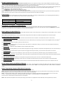
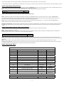
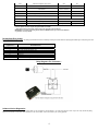
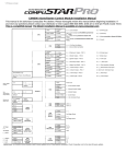
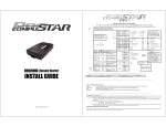
Version Final - VF
CM4200 and CM1000S Starter Control Module Installation Manual
This manual is for authorized CompuStar dealers. Please thoroughly review this manual before beginning installation. If you
have any questions please contact your distributor or tech support 888-820-3690. (8:00 am to 5:00 pm Pacific Coast Time)
This is a simplified manual. The Master Installation Manual is available on www.compustar.com.
CN1
OFF / ON
Alternator /
Tach
15 (25) / 25
(45)
Gas (Diesel)
*JM1
Tach Switch
2 Green /
White
4 White
1: ( + ) 12v Constant
2: ( + ) Parking Light
3 Red/White
3: ( + ) 12v Constant
4: ( + ) Accessory
5 Blue
6 Yellow
5: ( + ) Output, *JM1
6: ( + ) Starter prewired to
Anti-Grind Relay
7 Green and
Red
8 Black
7: ( + ) Ignition prewired to
Anti-Grind Relay
8: ( - ) Ground
1 Red
Jumper
Cut = Auto | Uncut = Manual (Default)
DIP 1
Dip Switches
DIP 2
3
2nd Starter
2
2nd Acc
1
2nd Ign.
CN2
CN8
1
Green/White
( - ) Parking Lt. Output
250 mA
2
Red/Black
( - ) Starter Output
250 mA
3
Violet
( - ) Output to Starter Kill
250 mA
4
Black
( - ) Status Out (GWR)
250 mA
5
Orange
( - ) Rearm Output
250 mA
6
Orange/White
( - ) Disarm Output
7
White
( - ) Horn Output
1
Lt. Blue
( - ) E-Brake Input
2
( - ) Hood Input
( + ) Brake Input
4
Gray/Black
Lt.
Blue/White
Violet/Black
5
Red/White
( - ) Door Input
6
Red
( + ) Door Input
7
Brown/Black
( - ) Glow Plug Input
8
Brown/White
( + ) Glow Plug Input
9
Yellow/Black
Tach / Alternator Input
( - ) Aux Wire (CM1000S)
CN12
SW
TX
4
White
RX
3
Blue
(-)
2
Black
(+)
1
Red
4
(-)
3
(+)
2
Tx
1
Rx
3
(-)
2
Temp
1
(+)
3
CN7
RS232
CN3
CN11
Antenna
CN4
CN5
Temp.
Sensor
( - ) Trunk Input
1
None
2
Violet/White
( - ) Trunk Release Output
3
Orange/Black
( - ) 2nd Unlock Output
250 mA
4
Blue
( - ) Unlock Output
250 mA
5
Blue/Black
( - ) Lock Output
250 mA
6
None
250 mA
IMPORTANT:
CN7 RS232 Port – Firstech recommends not using this port for 1 or 2 way datalink connections. The protocol from the CM4200 and CM1000-S does not always match that of the current
bypass modules and may cause issues. Power and ground are still available for this port however we recommend hardwiring all bypass modules.
Additional Items to Install
Antenna
Usually mounted on the front windshield. Stay at least 1 to 2 inches away from metal and try to mount below the tint stripe. IMPORTANT: use caution when
running the antenna cable and keep it free from snags and where it can be pinched when reassembling the vehicle.
Hood Pin
This is included in the wiring kit and Firstech recommends installing this in any vehicle. This is to prevent any injury or damage if the hood is open and the remote
start is engaged.
1
Remote Programming Procedure
You must program any and all remotes before the CompuStar is operational. Before you can program the remote(s) you must complete installation. Otherwise the only wires
needed to program the remote(s) are the 12v (+) constant wires (red and red/white), the ground wire (black), and the ignition wire (green). You must have the antenna connected to the
main controller. All remotes must be programmed at the same time. Here are the steps for remote programming:
STEP 1: Turn the key in the ignition from the Off or ACC position to the On or IGN position 5 times within 7 seconds. After the 5th ignition cycle you will hear the parking light relay click.
This will happen after the 5th cycle so it is easy to miss. If you hear two relay clicks and parking light flashes, the system has just exited remote programming mode.
STEP 2: Right after the 5th cycle and hearing the first relay click:
A. 1-Way Remote: Tap the lock button on the remote for 0.5 seconds.
B. 2-Way Remote: Tap button I for 0.5 seconds. 2WSSR place battery in remote.
STEP 3: After tapping the button on the remote, you will hear the parking light relay click once to indicate that it has accepted the remote. If you have other remotes to program to the
system, repeat step 2 for each remote, one after the other. Each system can accept three remotes with the exception of the 2WSSR.
Tach Learning
When you go to learn the tach by tapping the tach learn button on the side of the control module. You should get 1 parking light flash. If you see 3 parking light flashes followed by a
certain amount then there is an error. This table shows you what the second set of flashes represent.
Number of Parking Light Flashes
1
2
3
Tach Error
Dip switch is not in on position
Key is in the off position
Bad tach signal. Find a different wire.
Green/White Loop (CM3000 and CM4200 Models)
This loop wire determines the transmission setting. The default position (uncut loop) is for manual transmissions. When the loop is cut, the system will be ready for automatic
transmissions. In the default (manual transmission) mode, the system must be set up in Reservation mode prior to the vehicle being able to remote start. IMPORTANT: All warranties
or claims are void if a controller with a cut loop is installed on a vehicle with a manual transmission.
Option Settings You Need OP500 For:
Option 1-08 Diesel Timer is default to 10 seconds. You can set this option with either a 4 button 1 Way or 2 Way remote. To change the time you need the OP500. LCD Line 1 will read
DISL after Menu 2.
Option 2-06/2-07/1-03 No Tach Sensing. To change settings for tachless sensing please use the OP500. The old CM3 series programmer will not access these options.
Common Option Menu Descriptions
1-01 Unlock before, Lock after remote starting - Doors will unlock to remote start and then relock once started. This is to disarm factory alarms on certain vehicles.
1-04 Driver’s priority unlock - The driver’s door must be isolated from the other doors. Blue becomes your first unlock ground pulse. Use the Orange/Black CN4 as your negative 2nd
Unlock output.
1-05 Double pulse unlock - Sends two negative (-) pulses on the blue unlock wire.
1-08 Diesel Timer - Without setting this option you must find the vehicle’s wait to start wire. The default time for Setting 2 is 10 seconds. This can be increased or decreased only
with the Option Programmer OP500.
1-10 Starter kill relay – If installed the system will disable the vehicle from starting while it is locked.
1-12 Dome light delay - This setting will allow you to use the vehicle’s dome light as a door trigger. This delay is to compensate for dome lights that stay on for a few seconds after you
close the last door.
1-13 Factory style alarm - This feature allows the system to monitor the door triggers while the system is locked. If you open the doors it will honk the horn if connected.
1-14 Trigger Start Input - This option turns on the triple pulse (-) input on the center pin of the Temp. Sensor Plug. Otherwise a single (-) pulse will activate the remote start.
2-03 No Connection - 1 Second Crank – This option creates a 1 second crank output on the yellow starter wire. Should only be used for vehicles with built in anti-grind and automatic
transmission vehicles.
2-04 IGN + ACC Pulse with Disarm - This allows you to create pulses on the ignition and accessory wires on connector 1 at the same time Disarm Wires.
2-05 Ignition controlled door locks - Default setting locks doors when foot on foot brake. Unlocks doors when key turned off or when e-brake set on manual transmissions.
2-06 No Tach sensing mode - on the VS1, VD and VF versions the module can remote start automatic transmission vehicles without the use of a tach or alternator sense wire.
How to Change Options with OP500 and Remotes
The options can be set using the OP500 Option Programmer, 1 Way remote, 2 Way remote, or the antenna button on Canadian ANT-1WAM or ANT-1WSH. Firstech recommends using
an OP500 Option Programmer since not all options are accessible with the remotes or antenna buttons. NOTE: You cannot change options with the 1 Button, CM1000-S, or 2BSHLED
remotes.
Option Programming Using the OP500 Option Programmer
The OP500 can be used to program any available option. It is required to program the Diesel Timer.
STEP 1: Using the blue connector on the top of the OP500, connect it to the control module via the antenna wire. (Use the included extension cable if necessary.) Once connected,
the OP500 will power up as long as the main ignition harness to the controller has been connected properly.
STEP 2: To change the option number you wish to program, use the left and right arrow keys on the OP500. It will scroll through the options available in menu 1 and then move
to menu 2. Use the up and down arrow buttons on the OP500 to adjust the option settings; “1” is the default setting, and “2” is the optional setting.
At the end of menu 2, if diesel mode is the wait to start time can now be adjusted.
STEP 3: When finished with the adjustment of the various option settings, press and hold the “W” (Write) button until the OP500 chirps, which is approximately 2.5 seconds.
2
This will write the settings to the control module. Wait until the module displays “Success” before disconnecting it from the antenna cable.
To reset the options, hold the “R” (reset) button and “W” (write) button for 2.5 seconds. To write the reset, hold the “W” button until the OP-500 chirps, which is approximately 2.5 seconds.
Option Programming Using a Remote
Using a remote is a timed process so read this section in its entirety before beginning. IMPORTANT: Diesel timer cannot be programmed with a remote – the OP500 must be used. If at
any time during the process you hear a long horn sound the system kicked you out of programming mode.
STEP 1: Select the option menu that contains the desired programming option. To select a menu, use the following button combinations:
I+II for 2.5 sec.
I+IV for 2.5 sec
Menu 1
Menu 2
*Buttons I, II, III, IV correspond to I = Lock, 2 = Unlock, 3 = Trunk, 4 = Start on 1 Way remotes
STEP 2: After entering the option menu that contains the desired option, tap button (IV) on two-way remotes for 0.5 seconds or buttons (Trunk + Start) on one-way remotes
for 2.5 seconds the number of times equal to the option number. Wait for a parking light flash and siren chirp between each button press. After selecting the desired option number
the system will confirm which option you have selected by the number of siren chirps and parking light flashes.
STEP 3: Once the system is finished confirming the option number, set the option to the desired setting by tapping buttons I or II. To set options with the one-way remote the
duration is different. Tap the Lock Button for Setting 1. Tap the Unlock Button for Setting 2.
Resetting to Factory Defaults: To reset the options in a particular menu group, enter the menu by following STEP 1, then tap button III for 0.5 sec, three times. Wait for the siren to chip
and parking lights to flash between each tap. After the third tap, the option menu will reset and the siren will chirp three times. This must be done for each option group that needs to
be reset.
Option Programming Using the 1-Way Antenna Button
Programming the main controller option using an antenna is a timed process so you should read the instructions entirely before beginning.
STEP 1: Turn vehicle’s ignition to the on position.
STEP 2: Selecting the Option Menu - Select the option menu that contains the option you would like to adjust. Be aware, the diesel timer and auxiliary times are not available when
programming options with an antenna. To select a menu, use the following button combinations:
Hold antenna button until you hear/see 1 chirp/parking light flash.
Hold antenna button until you hear/see 2 chirps/parking light flashes.
Menu 1
Menu 2
STEP 3: Selecting the Specific Option - After entering the option menu that contains the option you wish to change, tap the antenna button the number of times equal to the option
number. you wish to change. A few seconds after you have stopped selecting an option, the system will confirm which option you have selected by the number of siren chirps and parking
light flashes.
STEP 4: Setting the Option - After the system is finished confirming the option number, set the option to your desired setting by tapping the antenna button 1 or 2 times.
Resetting to Factory Defaults: To reset the options in a menu, enter the menu as if you were going to program an option then hold the antenna button for three seconds. The option
menu will reset and the siren will chirp three times. The options in the other three menus will remain set.
Option Programming Tables
Option Menu 1
Feature
Factory Default - I
Optional - II
1-01
Unlock Before, Start, Lock After Start
OFF
ON
1-02
Door lock / Unlock Pulse Duration
0.8 sec
2.5 sec
1-03
Crank Time w/ Alternator Sensing
0.8 sec
1.0 sec
1-04
Driver's Priority Unlock
OFF
ON
1-05
Double Pulse Unlock
OFF
ON
1-07
Turbo Mode
OFF
ON
1-08
Diesel Timer *
Glow Plug Wire
3-99 sec.
(10 sec. default)
1-09
Short Pulse Lock / Unlock
OFF
0.125 Sec
1-10
Starter Kill Relay
Anti-Grind Only
1-11
Manual Transmission Auto Lock
Lock After
Reservation
Anti Grind + Starter
Kill
Does Not Lock After
Reservation
1-12
Delayed Door Trigger for Locking
OFF
90 Sec Delay
1-13
Factory Style Alarm
OFF
ON
Rearm Wire Pulse
After Remote Start
Shutdown and First
Lock
After Remote Start
Shutdown Only
Factory Default - I
Optional - II
1-14
Option Menu 2
Feature
3
2-01
Cold Start w/ Optional Temp. Sensor
OFF
ON
2-02
Timer Start or Minimum Interval Between Cold Starts
3 Hours
1.5 Hours
2-03
No Connection - 1 Second Crank - Not For Manual
Transmissions
Normal Start with
Tach or Alternator
1 Second Crank
2-04
IGN + ACC Pulse with Disarm
OFF
ON
2-05
Ignition Controlled Door Locks
OFF
ON
2-06
Engine Sensing
Tach or Alternator
2-07
No Tach Sensing Crank Time Increase
2-08
Tach Sensing Method
Optimal Tach Method
Previous Tach Method
2-09
Trigger Start Input
Single Pulse
Triple Pulse
No Tach Sensing
See Table Below
* Denotes Options That Can Only Be Programmed With The OP500
^ These Option Tables Can Change, Please Check www.compustar.com For Changes
IMPORTANT: You cannot program any options with the CM1000S remote, you must use the OP500 or
any 4 button 1 or 2 way remote
Remote Start Error Codes
If the remote start fails to start the vehicle, the parking lights will flash three times immediately. Following those three flashes the parking lights will flash again corresponding to the error
table.
Number of Parking
Light Flashes
1
2
3
4
5
6
7
8
Remote Start Error
Motor running
Key in ignition on position
Door open (manual transmission only)
Trunk open
Foot brake on
Hood open
Reservation off (manual transmission only)
CM4200-A still has the green/white loop intact. Cut
Relay Diagrams For Connector 1
Software Version Diagnostics
This is a new feature added with VD or newer software. When you turn the ignition on and hold buttons I + IV on the 2 Way remotes or Lock + Key on the 1 Way remotes the parking
lights and LED will flash to show which version software is on the control module. Version VD will show up as 1 parking light flash.
4
Frequently Asked Questions
I have everything hooked up and the system will not respond.
A: The remotes need to be programmed. Review the “Remote Programming Procedure” section of this manual.
Can I use the RS232 Port on the control module for my bypass module?
A: No, Firstech recommends hardwiring all the bypass modules because certain protocols on the control module may cause issues. You can still use the power and ground pins off that
plug however cutting the RX and TX wires should eliminate the possibility of any issues.
What do I do with the thick blue wire on CN1 and the Jumper in the control module?
A: The blue wire is prewired to an internal relay inside the control module. The jumper controls how that wire powers up. It should be defaulted to power up as an Ignition.
What is the violet wire with a butt connecter on CN2 for?
A: This wire should be connected to the short violet wire on the anti-grind relay. This is only used if you install the included anti-grind relay.
I am trying to program the control module with the OP500 Option Programmer. What port should I plug into?
A: You unplug the antenna cable at the antenna then plug in the optional extension cable. The male end of the extension cable should plug into the blue port on the top of the OP500.
When the OP500 is working properly, it will read “success good.”
How do I connect the Anti-Grind / Starter Kill relay?
A: As shown in the diagram above the relay has two wires, a yellow/black and yellow. You interrupt the vehicle’s starter wire and the yellow/black will always go to the key side. The
yellow will always go to the motor side.
Do the (-) door lock outputs (blue and blue/black) flip flop in polarity?
A: No to change the polarity you must use the DM600 polarity changing harness, the CompuPak, or 2 relays to change the output from (-) to (+).
I need a ground when armed wire for i.e. window modules, does control the module have one?
A: To activate this you must first program option 1-10. You can use the violet wire on CN1 that goes to the starter kill relay. You must cut this wire and place a diode in line so that when
the ignition on the other side of the relay goes to ground, it won’t back feed to your accessory. Install the stripe side of the diode facing the control module.
Drive Lock (Ignition Controlled Door Locks) are programmed but still do not function. What is wrong?
A: Once you program Option 2-05 the doors will lock when you hold the foot brake. This will not happen if the doors are open and you have not connected the (+) foot brake wire.
Are the CompuStar Pro 2 Way remotes compatible with the CM4200?
A: No, you must reinstall a new control module.
Can I program options with the 1 Button, CM1000-S, or 2BSHLED remotes?
A: No, you cannot change options with the 1 Button, CM1000-S, or 2BSHLED remotes. You must use a 4 button 1WAMR or higher.
How do I know what antenna pairs up to the remote?
A: Check a few things on both antenna and remote(s): The FCC ID number should be similar on both remote and antenna. The model numbers should also be similar for example: ANT2W900FM(TC) will pair up with the 2W900FMR.
I have the CM1000-S remote. Is it compatible with a CM4200?
A: No, this remote will only work with CM1000-S control modules.
How do I set reservation mode?
A: Reservation mode requires connecting the e-brake wire, tach and door trigger(s). While the vehicle is running with the key, set the e-brake. Wait a few seconds and then take the key
out of the ignition. The vehicle should stay running until you open and close all the doors. After a few seconds after the vehicle stops running you can remote start.
5
Technical Support Contacts
Firstech technical support is reserved for authorized dealers only.
Monday - Friday
888-820-3690
(8:00 am – 5:00 pm Pacific Coast Time)
Email
[email protected]
Web
http://www.compustar.com click on “dealer support”
Wire Diagrams
Click on the “Installogy Access Client” link found on your desktop. If you are a qualified dealer
and unable to access this site, call your sales representative or the number above.
www.compustar.com
Toll Free: 888-820-3690
th
21911 68 Ave S
Kent, WA 98032
6