1
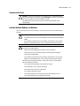
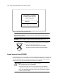
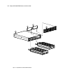
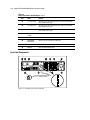
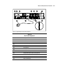
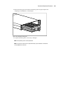
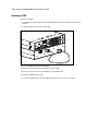
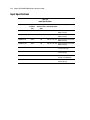
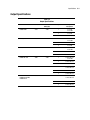
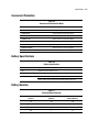
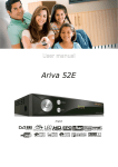
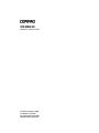
UPS R3000 XR
Maintenance and Service Guide
First Edition (September 2000)
Part Number 221891-001
Spare Part Number 223932-001
Compaq Computer Corporation
Notice
© 2000 Compaq Computer Corporation
COMPAQ, the Compaq logo, Compaq Insight Manager, and SmartStart Registered in U.S. Patent and
Trademark Office.
All other product names mentioned herein may be trademarks of their respective companies.
Compaq shall not be liable for technical or editorial errors or omissions contained herein. The information
in this document is subject to change without notice.
THE INFORMATION IN THIS PUBLICATION IS PROVIDED “AS IS” WITHOUT WARRANTY OF
ANY KIND. THE ENTIRE RISK ARISING OUT OF THE USE OF THIS INFORMATION REMAINS
WITH RECIPIENT. IN NO EVENT SHALL COMPAQ BE LIABLE FOR ANY DIRECT,
CONSEQUENTIAL, INCIDENTAL, SPECIAL, PUNITIVE OR OTHER DAMAGES WHATSOEVER
(INCLUDING WITHOUT LIMITATION, DAMAGES FOR LOSS OF BUSINESS PROFITS,
BUSINESS INTERRUPTION OR LOSS OF BUSINESS INFORMATION), EVEN IF COMPAQ HAS
BEEN ADVISED OF THE POSSIBILITY OF SUCH DAMAGES AND WHETHER IN AN ACTION OF
CONTRACT OR TORT, INCLUDING NEGLIGENCE.
The limited warranties for Compaq products are exclusively set forth in the documentation
accompanying such products. Nothing herein should be construed as constituting a further or
additional warranty.
Compaq UPS R3000 XR
Maintenance and Service Guide
First Edition (September 2000)
Part Number 221891-001
Spare Part Number 223932-001
Contents
About This Guide
Symbols in Text .......................................................................................................... v
Compaq Technician Notes .........................................................................................vi
Where to Go for Additional Help ...............................................................................vi
Telephone Numbers ...........................................................................................vii
Chapter 1
Before You Begin
Safety and Product Information................................................................................1-1
Symbols on Equipment .....................................................................................1-1
Technician Notes...............................................................................................1-2
Rack ..................................................................................................................1-2
Weight ...............................................................................................................1-2
Communication Ports........................................................................................1-3
Extended Runtime Modules and Batteries ........................................................1-3
Remote Emergency Power Off (REPO)............................................................1-4
Chapter 2
Illustrated Parts List
Exploded View .........................................................................................................2-2
Chapter 3
Removal and Replacement Procedures
Before You Begin.....................................................................................................3-1
Replaceable Parts ..............................................................................................3-1
Tools Required ..................................................................................................3-2
Identifying Components ...........................................................................................3-2
Front Panel ........................................................................................................3-2
Front Panel Controls and LED Display.............................................................3-3
Rear Panel Components ....................................................................................3-4
Modes of Operation..................................................................................................3-6
Standby Mode ...................................................................................................3-6
Operate Mode....................................................................................................3-6
Configure Mode ................................................................................................3-6
Auto-Bypass Mode............................................................................................3-6
Powering Down the UPS..........................................................................................3-7
Emergency Shutdown .......................................................................................3-7
iv
Compaq UPS R3000 XR Maintenance and Service Guide
Removal and Replacement Procedures
continued
Replacing the UPS Battery Pack ..............................................................................3-8
Disposing of Used Batteries ............................................................................3-10
Replacing the Electronics Module..........................................................................3-11
Replacing an Option or Communication Board .....................................................3-14
Replacing the UPS Unit..........................................................................................3-16
Extended Runtime Modules ...................................................................................3-17
Replacing ERM Battery Packs ........................................................................3-17
Replacing an ERM ..........................................................................................3-20
Chapter 4
Troubleshooting
Troubleshooting During Start...................................................................................4-1
Troubleshooting After Start......................................................................................4-2
Chapter 5
Specifications
Physical Specifications.............................................................................................5-1
Input Specifications..................................................................................................5-2
Output Specifications ...............................................................................................5-3
Overcurrent Protection .............................................................................................5-5
Battery Specifications...............................................................................................5-5
Battery Runtime .......................................................................................................5-5
Environmental Specifications...................................................................................5-6
Index
About This Guide
This Maintenance and Service Guide is a troubleshooting guide that can be used for reference
when servicing Compaq R3000 XR series of Uninterruptible Power Systems (UPSs).
WARNING: To reduce the risk of personal injury from electrical shock and hazardous energy
levels, only authorized service technicians should attempt to repair this equipment. Improper
repairs could create conditions that are hazardous.
IMPORTANT: The installation of options and servicing of this product shall be performed by individuals
who are knowledgeable of the procedures, precautions, and hazards associated with equipment
containing hazardous energy circuits.
Symbols in Text
These symbols may be found in the text of this guide. They have the following meanings:
WARNING: Text set off in this manner indicates that failure to follow directions in the warning
could result in bodily harm or loss of life.
CAUTION: Text set off in this manner indicates that failure to follow directions could result in
damage to equipment or loss of information.
IMPORTANT: Text set off in this manner presents clarifying information or specific instructions.
NOTE: Text set off in this manner presents commentary, sidelights, or interesting points of information.
vi
Compaq UPS R3000 XR Maintenance and Service Guide
Compaq Technician Notes
WARNING: Only authorized technicians trained by Compaq should attempt to repair this
equipment. All troubleshooting and repair procedures are detailed to allow only
subassembly/module level repair. Because of the complexity of the individual boards and
subassemblies, no one should attempt to make repairs at the component level or to make
modifications to any printed wiring board. Improper repairs can create a safety hazard. Any
indications of component replacement or printed wiring board modifications may void any
warranty.
WARNING: To reduce the risk of personal injury from electrical shock and hazardous energy
levels, do not exceed the level of repair specified in these procedures. Because of the
complexity of the individual boards and subassemblies, do not attempt to make repairs at the
component level or to make modifications to any printed wiring board. Improper repairs could
create conditions that are hazardous.
WARNING: To reduce the risk of electric shock or damage to the equipment:
If the system has multiple power supplies, disconnect power from the system by
unplugging all power cords from the power supplies.
Do not disable the power cord grounding plug. The grounding plug is an important safety
feature.
Plug the power cord into a grounded (earthed) electrical outlet that is easily accessible at
all times.
CAUTION: To properly ventilate your system, you must provide at least 12 inches (30.5 cm) of
clearance at the front and back of the UPS.
CAUTION: The UPS is designed to be electrically grounded. To ensure proper operation, plug
the AC power cord into a properly grounded AC outlet only.
Where to Go for Additional Help
In addition to this guide, the following information sources are available:
■
User Documentation
■
Compaq Service Quick Reference Guide
■
Service Training Guides
■
Compaq Service Advisories and Bulletins
■
Compaq QuickFind
■
Compaq Insight Manager
■
Compaq Download Facility: Call 1-281-518-1418
TM
About This Guide
Telephone Numbers
For the name of your nearest Compaq Authorized Reseller:
■
In the United States, call 1-800-345-1518
■
In Canada, call 1-800-263-5868
For Compaq technical support:
■
In the United States and Canada, call 1-800-386-2172
■
For Compaq technical support phone numbers outside the United States and Canada, visit
the Compaq website at
http://www.compaq.com
vii
Chapter
1
Before You Begin
Safety and Product Information
WARNING: The Compaq Uninterruptible Power System (UPS) R3000 XR contains
hazardous voltage levels and energy circuits. There is a risk of personal injury from
electrical shock and hazardous energy levels. Persons performing installation or service
procedures must be Trained Service Technicians, knowledgeable about the procedures,
precautions, and hazards associated with AC Power Products.
Symbols on Equipment
These icons may be located on equipment in areas where hazardous conditions may exist.
Any surface or area of the equipment marked with these symbols indicates the
presence of electrical shock hazards. Enclosed area contains no operator
serviceable parts.
WARNING: To reduce risk of injury from electrical shock hazards, do not open this
enclosure.
Any surface or area of the equipment marked with these symbols indicates the
presence of a hot surface or hot component. If this surface is contacted, the
potential for injury exists.
WARNING: To reduce the risk of injury from a hot component, allow the surface to
cool before touching.
Any product or assembly marked with these symbols indicates that the component
exceeds the recommended weight for one individual to handle safely.
weight kg
weight lb
WARNING: To reduce the risk of personal injury or damage to the equipment,
observe local health and safety requirements and guidelines for manual material
handling.
1-2
Compaq UPS R3000 XR Maintenance and Service Guide
Technician Notes
WARNING: To reduce the risk of personal injury from electrical shock and hazardous energy
levels:
Only authorized technicians trained by Compaq should attempt to repair this equipment.
The installation of options and routine maintenance and service of this product must be
performed by Trained Service Technicians who are knowledgeable about the procedures,
precautions, and hazards associated with AC Power Products.
Do not exceed the level of repair specified in these procedures. All troubleshooting and
repair procedures are detailed to allow only subassembly/module level repair. Because of
the complexity of the individual boards and subassemblies, no one should attempt to make
repairs at the component level or to make modifications to any printed wiring board.
Improper repairs can create a safety hazard.
Remove all watches, rings, and any other metal or loose-fitting jewelry.
Avoid the use of conductive tools that could bridge live parts.
Rack
WARNING: To reduce the risk of personal injury or damage to the equipment, ensure that:
The leveling jacks are extended to the floor.
The full weight of the rack rests on the leveling jacks.
The stabilizing feet are attached to the rack for a single rack installation.
The racks are coupled in multiple rack installations.
You extend only one component at a time. A rack may become unstable if more than one
component is extended for any reason.
Weight
WARNING: The UPS R3000 XR weighs 82 lb (37 kg) when fully assembled. The
battery pack weighs 42 lb (19 kg). To reduce the risk of personal injury or
damage to the equipment:
82 lb
37 kg
Observe local health and safety requirements and guidelines for manual
material handling.
Obtain adequate assistance to lift and stabilize the product during
installation or removal.
Remove all pluggable options and batteries to reduce the overall weight of
the product.
Install the UPS R3000 XR and the Extended Runtime Modules (ERMs) only at
the bottom of the rack. If placed in a rack with existing equipment, the rack
must be reconfigured to allow installation of the UPS at the bottom of the
rack.
Mount the UPS R3000 XR only on the fixed rails included in the UPS
package. Refer to the appropriate installation card and rack template,
shipped with the UPS R3000 XR kit, for instructions on rack-mounting the
UPS.
Before You Begin
Communication Ports
CAUTION: To reduce the risk of damage to the equipment, only use the DE9 UPS/Computer
Interface cable supplied by Compaq (part number 201092-00X) to connect the communications
port to the host computer. Do not use standard RS-232 cables.
This UPS/Computer Interface Cable carries power and is specifically designed for UPS
communications.
Extended Runtime Modules and Batteries
Observe these precautions when handling or connecting batteries and Extended Runtime
Modules.
WARNING: To reduce risk of personal injury from electric shock or damage to equipment:
A Trained Service Technician must install all batteries and the Extended Runtime Modules
(ERMs).
Do not attempt to replace batteries unless all battery circuit breakers on any connected
ERMs are in the OFF (down) position. There is a 120-volt potential across the batteries.
WARNING: To reduce the risk of personal injury or equipment damage, adhere to the following
precautions when handling batteries:
Make sure that only qualified personnel handle or connect the batteries.
Remove watches, rings, or other metal objects prior to working with the equipment.
Use tools with insulated handles.
Do not attempt to replace batteries unless all battery circuit breakers on any connected
ERMs are in the OFF (down) position. There is a 120-volt potential across the batteries.
This UPS contains sealed lead-acid batteries. To reduce the risk of fire or chemical burns,
adhere to the following precautions:
Do not attempt to recharge batteries after removal from the UPS.
Do not disassemble, crush, or puncture the batteries.
Do not short the external contacts of the batteries.
Do not immerse the batteries in water.
Do not expose the batteries to temperatures higher than 60°C or dispose of in fire.
Use only the Compaq battery spare designated for this UPS.
1-3
1-4
Compaq UPS R3000 XR Maintenance and Service Guide
THIS PRODUCT CONTAINS
A NONSPILLABLE BATTERY
Next Recharge Date:
14-DEC-01
Please refer to Maintenance Section
of Owner's Manual enclosed inside
Figure 1-1. Checking the battery recharge date label
IMPORTANT: Do not use the batteries if the recharge date has passed (Figure 1-1). If the date on the
Battery Recharge Date Label has passed without the batteries being recharged, contact an Authorized
Compaq Service Representative.
IMPORTANT: Compaq recommends that you do not maintain an inventory of spare batteries on-site
unless you implement a procedure to keep these batteries charged while in storage.
Do not dispose of used batteries with general office or household waste.
Return the used battery for proper disposal to:
Compaq, your authorized Compaq Partners, or their agents
A recycling center that meets all local environmental standards
Pb
Remote Emergency Power Off (REPO)
If the UPS R3000 XR is to be installed in a computer equipment room, it must be connected to a
Remote Emergency Power Off (REPO) circuit. The UPS R3000 XR REPO port is designed to
meet the requirements stated in National Electrical Code (NFPA 70) Article 645-10 and 11 in
North America or the equivalent local and/or national wiring regulations.
WARNING: To reduce risk of personal injury or damage to equipment:
Only a licensed electrician can wire the REPO port.
Verify that the main breaker switch is in the OFF position before wiring the REPO port.
In North America, the REPO circuit must comply with the NEC (NFPA 70, Article 725) for a
Class 2 circuit. The REPO port wiring must also meet all other national and local standards
in the area in which it is installed.
Chapter
2
Illustrated Parts List
This chapter provides the illustrated parts breakdown and a spare parts list for the Compaq UPS
R3000 XR. See Table 2-1 for the names of referenced spare parts.
2-2
Compaq UPS R3000 XR Maintenance and Service Guide
Exploded View
6
5
2
1
3
4
Figure 2-1. Exploded view, Compaq UPS R3000 XR
Illustrated Parts List
Table 2-1
UPS Spares Parts List
Ref
Description
Spares Part #
1
UPS Chassis
**
2
Front Bezel
204507-001
3
Electronics Module (low voltage)
204506-001
Electronics Module (high voltage)
216097-001*
4
UPS Battery Pack
204503-001
5
Battery Bracket
**
6
X-Slot Serial Board
204514-001
7
UPS L530-NA
222383-001*
UPS L530-JP
222383-291*
UPS 620H-NA
222384-001*
UPS DTC-INTL
222385-002*
UPS 309-EURO
222386-021*
8
Cord Retention Clip
204505-001*
9
Front and Rear Mounting Brackets
204504-001*
-
Mounting Rail
322578-002*
q
Maintenance and Service Guide
223932-001*
w
UPS to server interface cable
204508-001*
e
UPS to UPS interface cable
204509-001*
Cables
* Not shown
** No spare available
2-3
2-4
Compaq UPS R3000 XR Maintenance and Service Guide
15
15
16
17
14
14
Figure 2-2. Exploded view, Extended Runtime Module
Illustrated Parts List
Table 2-2
Extended Runtime Module Spares Parts List
Ref
Description
Spares Part #
r
Battery Packs
204503-001
t
Battery Brackets
**
y
Front Bezel
204511-001
u
Chassis for Extended Runtime Module
**
i
Extended Runtime Module
204510-001*
o
Front and Rear Mounting Brackets
204504-001*
p
Mounting Rail
322578-002*
ERM to UPS Cable
216092-001*
Cables
a
* Not shown
** No spare available
2-5
Chapter
3
Removal and Replacement Procedures
This chapter provides guidance for removing and replacing spare parts in the Compaq UPS
R3000 XR.
Before You Begin
WARNING: The Compaq UPS R3000 XR is a high-energy product. There is a risk of personal
injury from electrical shock and hazardous energy levels. Persons performing installation or
service procedures must be Trained Service Technicians, knowledgeable about the procedures,
precautions, and hazards associated with high-energy AC Power Products.
Before beginning any of the procedures in this chapter, read and understand the cautions and
warnings in Chapter 1, “Before You Begin.”
Replaceable Parts
The UPS R3000 XR contains the following replaceable parts:
! Front bezel
! UPS battery pack
! Electronics module
! Option or communication board
! UPS unit
! ERM battery packs
! Extended Runtime Modules (ERMs)
3-2
Compaq UPS R3000 XR Maintenance and Service Guide
Tools Required
To service a UPS R3000 XR, you need one or more of the following:
■
#2 Phillips screwdriver
■
¼-inch driver
■
Compaq Power Management Utility (from the Compaq SmartStart
Software CD)
■
Voltmeter to verify the nominal voltages to ensure proper configuration
TM
and Support
Identifying Components
Use the following illustrations to locate and identify the components of the UPS R3000 XR.
Front Panel
1
2
3
Figure 3-1. Front panel
Table 3-1
Front Panel Component Identification
Item
Description
1
Battery compartment
2
Control buttons
3
LED display
Removal and Replacement Procedures
Front Panel Controls and LED Display
The UPS front panel contains four control buttons and ten LEDs that create the interface for
setup, configuration, load control, and status monitoring.
1
2
3
4
5
15
6
7
8
9
14
10
13
12
11
Figure 3-2. Front panel controls and LED display with front bezel removed
Table 3-2
Front Panel Controls and LED Display
Item
Name
Function
1
General Alarm
Indicates a general alarm when red
2
On Battery
Indicates that the battery is on when red
3
Bad Battery/Low
Battery
Indicates that the battery is bad or low when red
4
Site Wiring Fault
Indicator
Indicates a wiring fault when red
5
Utility LED
Indicates that:
The unit is in Auto-Bypass mode when red
The utility voltage is present and output is on when green
The utility input voltage is outside nominal range when flashing red
The utility voltage is present and the UPS is in Standby mode when
flashing green
6
Overload LED
Indicates that the UPS exceeds maximum power available when red
7
76% to 100% load
Indicates that the UPS is approximately 76% to 100% of the maximum
power available when green
continued
3-3
3-4
Compaq UPS R3000 XR Maintenance and Service Guide
Table 3-2
Front Panel Controls and LED Display continued
Item
Name
Function
8
51% to 75% load
Indicates that the UPS is approximately 51% to 75% of the maximum
power available when green
9
26% to 50% load
Indicates that the UPS is approximately 26% to 50% of the maximum
power available when green
-
0% to 25% load
Indicates that the UPS is approximately 0% to 25% of the maximum
power available when green
q
Configure mode
on LED
Indicates that the UPS is in Configure mode
w
Configure button
Places the UPS in Configure mode
e
TEST/ALARM
RESET button
Initiates a self-test and silences audio alarms
r
STANDBY button
Places the UPS in Standby mode
t
ON button
Places the UPS in Operate mode
Rear Panel Components
1
2
11
3
4
10
Figure 3-3. Low voltage unit rear panel components
5
6
9
7
8
Removal and Replacement Procedures
1
2
11
3
4
5
10
6
9
Figure 3-4. High voltage unit rear panel components
Table 3-3
Rear Panel Components
Item
Description
1
REPO port
2
ERM connector
3
Communications port/Options slot
4
Load segment 1
5
Load segment 2
6
Load segment 3
7
Load segment circuit protectors
8
Compaq PDU output receptacle (Load segment 1)
9
Cord retention clip attachment locations
:
Ground bonding screw
;
Power cord with plug
7
8
3-5
3-6
Compaq UPS R3000 XR Maintenance and Service Guide
Modes of Operation
The UPS has four modes of operation: Standby, Operate, Configure, and Auto-Bypass.
Standby Mode
Place the UPS in Standby mode by pressing the STANDBY button on the front panel. During
Standby mode:
■
No power is available at the UPS output receptacles.
■
The UPS charges the batteries as necessary.
Operate Mode
Place the UPS in Operate mode by pressing the ON button on the front panel. During
Operate mode:
■
Power is available at the UPS output receptacles.
■
The UPS charges the batteries as necessary.
Configure Mode
Place the UPS in Configure mode by removing the front bezel and pressing and holding the
Configure button on the front panel until the Configure mode on LED turns solid green. In the
Configure mode, the front panel LED display changes function. The LED display and control
buttons let you monitor and change the UPS configuration parameters.
In the Configure mode:
■
Press the ON button to advance to the next configuration mode.
■
Press the TEST/ALARM RESET button to accept the select configuration.
■
Press the STANDBY button to turn the LED configuration on or off.
While the UPS is in Configure mode:
■
Power is available at the UPS output receptacles.
■
The UPS charges the batteries as necessary.
■
The configuration of the UPS can be updated.
Auto-Bypass Mode
The UPS automatically switches to Auto-Bypass mode if the following conditions occur:
■
The power (wattage) to the unit reaches a percentage greater than 110 percent for 10
cycles or 103 percent for 30 seconds.
■
The UPS power module fails or is removed.
Removal and Replacement Procedures
Powering Down the UPS
To completely remove power from the UPS:
1. Power down all equipment being supported by the UPS (attached loads).
2. Place the UPS in Standby mode by pressing the STANDBY button on the front panel.
3. Disconnect the UPS from utility power.
4. Wait at least 60 seconds for the UPS internal circuitry to discharge.
Emergency Shutdown
Compaq UPS R3000 XR models include a Remote Emergency Power Off (REPO) port as
required by the National Electric Code (NFPA 70). The REPO port allows you to shut the UPS
down from a remote location. You can connect the REPO ports of multiple UPSs to a single
switch or circuit to shut down your entire system in an emergency.
IMPORTANT:
The REPO feature shuts down protected devices immediately and does not follow the orderly
shutdown procedure initiated by Compaq Power Management Software.
The REPO feature shuts down devices that are operating under either utility or battery power.
If the UPS was operating on battery power when the remote switch was closed, no power will be
available to the devices until utility power is restored and the devices are manually powered up.
The UPS R3000 XR REPO circuit is an IEC950 Secondary Extra Low Voltage (SELV) circuit.
The computer room Emergency Power shutdown circuit conductors that connect to the REPO
terminals must:
■
Meet the requirements of an NEC Class 2 circuit or IEC950 Secondary Extra Low Voltage
(SELV) circuit
■
Be separated from any hazardous voltage circuits or conductors by reinforced insulation
■
Short the UPS R3000 XR REPO terminals.
■
Disconnect the UPS R3000 XR AC input source.
To shut down the system:
1. Place the UPS on Standby.
2. Disconnect the mains by opening the switch or circuit breaker at the utility panel.
WARNING: To reduce the risk of electrical shock and/or equipment damage, use a
Lockout/Tagout procedure to isolate the UPS R3000 XR from AC power before wiring the
product or replacing a non-hot-plug component.
3-7
3-8
Compaq UPS R3000 XR Maintenance and Service Guide
Replacing the UPS Battery Pack
When the Bad Battery/Low Battery LED 1 turns red, the battery pack will need to be replaced
within 30 to 60 days.
1
100%
1
25%
Figure 3-5. Bad Battery/Low Battery LED
Verify that battery replacement is required by initiating a UPS self-test (press the
TEST/ALARM RESET button). If the red LED is still flashing after the test, replace the
batteries.
NOTE: Depending on usage and environmental conditions, the batteries should last three to six years.
The battery packs are accessed from the front of the unit.
NOTE: Batteries can be replaced (hot-swapped) without powering off the UPS if the UPS is not supplying
battery power to devices (utility is present, indicating that the UPS is supplying utility power). To replace
batteries with the UPS power off, follow the procedure in “Powering Down the UPS,” in this chapter.
Removal and Replacement Procedures
To replace the battery pack:
1. Obtain access to the battery pack by pulling on both ends of the front bezel 1 to remove
it.
2. Locate the two screws 2 on the metal battery bracket 3.
3
1
2
Figure 3-6. Removing the front bezel
3. Remove the two screws 1 and lift off the metal battery bracket 2.
1
2
1
Figure 3-7. Removing the battery bracket
3-9
3-10
Compaq UPS R3000 XR Maintenance and Service Guide
4. Pull out the battery pack. Set aside the used battery pack for proper disposal. See
“Disposing of Used Batteries,” in this chapter.
Figure 3-8. Removing the battery pack
WARNING: The UPS R3000 XR battery pack weighs 42 lb (19 kg). Prepare the area and
observe all materials handling procedures for removing the battery pack.
5. Slide the new battery pack into the chassis.
6. Replace the metal battery bracket and secure the two screws.
7. Snap on the front bezel.
8. Initiate a UPS self-test by pressing the TEST/ALARM RESET button.
Disposing of Used Batteries
The UPS uses sealed lead/acid batteries that must be disposed of in accordance with local
environmental regulations and laws.
If a local approved recycle/disposal site is not available, your replacement battery kit includes
the instructions and packaging required to return used batteries to an appropriate location for
disposal.
Do not dispose of used batteries with general office or household waste.
Return the used battery for proper disposal to:
! Compaq, your authorized Compaq Partners, or their agents
! A recycling center that meets all local environmental standards
Pb
Removal and Replacement Procedures
Replacing the Electronics Module
NOTE: The electronics module can be replaced (hot-swapped) without powering off the UPS. To replace
the electronics module with the UPS power off, follow the procedure in “Powering Down the UPS,” in this
chapter.
CAUTION: To avoid dropping the load while hot-swapping the electronics module, hold down
the TEST/ALARM RESET button while sliding the new electronics module into the chassis. The
TEST/ALARM RESET button is located on the UPS front panel.
To replace the electronics module:
1. Disconnect the communications cable.
Figure 3-9. Disconnecting the communications cable
3-11
3-12
Compaq UPS R3000 XR Maintenance and Service Guide
2. Obtain access to the electronics module by pulling on both ends of the front bezel 1 to
remove it.
3. Locate the two screws 2 on the electronics module 3.
2
3
1
Figure 3-10. Removing the front bezel
4. Remove the two screws 1 and pull out the electronics module 2.
2
1
Figure 3-11. Removing the electronics module
Removal and Replacement Procedures
CAUTION: To avoid dropping the load while hot-swapping the electronics module, hold down
the TEST/ALARM RESET button while sliding the new electronics module into the chassis.
3. Hold down the TEST/ALARM RESET button 1 on the front panel of the new electronics
module and slide the electronics module into the chassis 2. Do not release the
TEST/ALARM RESET button until the electronics module is firmly seated in the
connector, the Configure mode on LED flashes green, and a UPS self-test begins (about
four seconds).
1
2
Figure 3-12. Inserting the electronics module
5. Secure the two screws.
6. Snap on the front bezel.
7. Attach the communications cable.
3-13
3-14
Compaq UPS R3000 XR Maintenance and Service Guide
Replacing an Option or Communication Board
NOTE: The option or communication board can be replaced (hot-swapped) without powering off the UPS.
To replace the option or communication board with the UPS power off, follow the procedure in “Powering
Down the UPS,” in this chapter.
To remove an option or communication board:
1. Disconnect the external cable from the board.
Figure 3-13. Disconnecting option board cables
2. If the UPS is powered down, proceed to step 3.
If hot-swapping the board, remove the electronics module. See steps 2 through 4 in
“Replacing the Electronics Module.” The UPS switches to Auto-Bypass mode.
Removal and Replacement Procedures
3. Remove the screws securing the board to the UPS.
4. Pull the board out of the unit.
Figure 3-14. Removing an option board
5. Slide the new board into the UPS.
6. Tighten the screws that secure the board to the UPS.
7. If the UPS is powered down, proceed to step 8.
If hot-swapping the board, replace the electronics module. See steps 5 through 7 in
“Replacing the Electronics Module.”
CAUTION: To avoid dropping the load, hold down the TEST/ALARM RESET button while sliding
the new electronics module into the chassis.
8. Reconnect the external cable.
NOTE: Replacing the communication board resets the timer and schedules.
NOTE: The power management software may need to be rebooted after hot-swapping the board.
3-15
3-16
Compaq UPS R3000 XR Maintenance and Service Guide
Replacing the UPS Unit
To replace the UPS:
1. Power down the UPS. Follow the procedure in “Powering Down the UPS,” in this chapter.
2. Turn all battery circuit breakers on the ERMs (one circuit breaker each) to the Off
position.
Figure 3-15. Switching the circuit breaker to the Off position
3. Unplug the UPS power cable.
4. Unplug connected devices and remove the retention clips that secure device cables to the
UPS.
5. Unplug an attached ERM from the back of the UPS.
Figure 3-16. Unplugging the Extended Runtime Module
Removal and Replacement Procedures
6. Remove the UPS front bezel.
7. Remove the screws that secure the UPS to the front of the rack.
8. Remove the UPS from the rack.
9. To replace the UPS, place the new unit in the rack and reverse steps 1 through 7.
Extended Runtime Modules
Extended Runtime Modules (ERMs) are supported by the Compaq UPS R3000 XR. The UPS
rear panel provides a power receptacle where the module is attached. The UPS R3000 XR ERM
contains two battery packs in a 2U chassis and extends the available UPS runtime up to 30
minutes.
NOTE: These figures were derived using the Compaq-recommended 80 percent load.
Replacing ERM Battery Packs
NOTE: The battery packs can be replaced (hot-swapped) without powering down the UPS.
To remove battery packs from an ERM:
1. Switch the circuit breaker on the rear of the ERM to the Off position.
Figure 3-17. Switching the circuit breaker to the Off position
3-17
3-18
Compaq UPS R3000 XR Maintenance and Service Guide
2. Obtain access to the battery packs by pulling on both ends of the ERM front bezel to
remove it.
Figure 3-18. Removing the ERM front bezel
3. Remove two screws 1 from each metal battery bracket and lift off the battery brackets 2.
1
2
1
Figure 3-19. Removing the battery bracket
Removal and Replacement Procedures
4. Pull out the battery packs. Set aside the used battery packs for proper disposal. See
“Disposing of Used Batteries,” in this chapter.
Figure 3-20. Removing the battery packs
5. To replace the battery packs, reverse steps 1 through 4.
NOTE: The right battery pack is inserted upside down.
NOTE: To increase the useful life of the replacement battery, replace all batteries in the UPS and
connected ERMs at the same time.
3-19
3-20
Compaq UPS R3000 XR Maintenance and Service Guide
Replacing an ERM
To replace an ERM:
1. Turn all battery circuit breakers on all attached ERMs (one circuit breaker each) to the Off
position.
2. Unplug the ERM from the back of the UPS.
Figure 3-21. Unplugging the Extended Runtime Module
4. Remove the front bezel from the ERM you want to replace.
5. Remove the screws that secure the ERM to the front of the rack.
6. Remove the ERM from the rack.
7. To replace the ERM, place the new ERM in the rack and reverse steps 1 through 4.
Chapter
4
Troubleshooting
This chapter provides information on the following topics:
■
Troubleshooting problems that occur during UPS start
■
Troubleshooting problems that occur after UPS start
Troubleshooting During Start
If problems occur when starting the Compaq UPS R3000 XR models, select the appropriate
symptom for possible causes and suggested actions.
Table 4-1
Troubleshooting Guide (UPS Start)
Symptom
Possible Cause
Suggested Action
UPS will not start
There is no utility power and the
batteries are not charged.
Check the power at the utility
power receptacle or contact a
qualified electrician.
The UPS power cord is
disconnected.
Connect the power cord.
The utility power receptacle is
ungrounded or there is no ground
wire in the UPS power cord.
Contact a qualified electrician to
correct the condition.
Line and neutral wires are
reversed in the utility power
receptacle or in the UPS power
cord.
For units factory-configured for
200V or 208V, the Site Wiring
Fault function has been disabled.
If reconfiguring a 230V unit to
operate at 208V, the Site Wiring
Fault function must be manually
disabled.
(high voltage models only)
Site Wiring Fault LED is red
continued
4-2
Compaq UPS R3000 XR Maintenance and Service Guide
Table 4-1
Troubleshooting Guide (UPS Start) continued
Symptom
Possible Cause
Suggested Action
Bad Battery/Low Battery LED is
flashing red
Battery voltage is low because the
UPS has been out-of-service for a
long period.
Allow the UPS to charge the
batteries for 24 hours. Initiate a
self-test. If the LED does not turn
off, replace the batteries.
The battery test failed.
Allow the UPS to charge the
batteries for 24 hours. Initiate a
self-test. If the LED does not turn
off, replace the batteries.
The battery is disconnected.
Install the battery pack. If the
battery pack is installed, remove it
and then insert it again.
Troubleshooting After Start
For problems that occur after the UPS has gone through the startup self-test sequence, these
suggested actions address possible causes.
Table 4-2
Troubleshooting Guide (After Start)
Symptom
Possible Cause
Suggested Action
Audio Alarm sounds
An alarm condition exists.
Identify the red LED associated
with the alarm condition. Check
this troubleshooting guide to
determine the cause of the alarm.
Utility LED and On Battery LED are
flashing red
The utility voltage is too high.
The utility voltage is higher than
the UPS operating range. The UPS
switches to battery power. If this
happens repeatedly, update the
configuration.
Contact a qualified electrician to
ensure that utility power is
suitable for the UPS.
Utility LED and On Battery LED are
flashing red
The utility voltage is too low.
The utility voltage is lower than
the UPS operating range. The UPS
switches to battery power. If this
happens repeatedly, update the
configuration.
Contact a qualified electrician to
ensure that utility power is
suitable for the UPS.
continued
Troubleshooting
Table 4-2
Troubleshooting Guide (After Start) continued
Symptom
Possible Cause
Suggested Action
Utility LED and On Battery LED are
flashing red
The utility frequency is out of
tolerance.
Contact a qualified electrician to
ensure that utility power is
suitable for the UPS.
Utility LED is flashing red
The utility input voltage is outside
the ±12% nominal range.
If this happens repeatedly, check
the input voltage and reconfigure
the unit.
Contact a qualified electrician to
ensure that utility power is
suitable for the UPS.
Utility LED is flashing green
The utility power is within the
acceptable range, but the output
is off.
Press the ON button.
UPS frequently switches between
utility and battery power
There are utility power variations.
The utility voltage is frequently
outside the UPS operating range.
Update the configuration.
Contact a qualified electrician to
ensure that utility power is
suitable for the UPS.
Overload LED is red
On Battery LED is flashing red
Protected devices are exceeding
the UPS power rating.
Remove one or more devices to
reduce the power requirements.
(UPS may switch from utility to
Auto-Bypass.)
Make sure that the devices are
not defective.
There is low battery voltage.
If the UPS is supplying battery
power, save current work and
shut down the system. Allow the
batteries to charge.
If the UPS is supplying utility
power, no intervention is required.
Allow the batteries to charge.
Insufficient warning of low
batteries
Battery service is required.
Allow the batteries to charge for
24 hours, then initiate a self-test.
If the LED is red, replace the
batteries.
The Shutdown Delay configuration
is inappropriate.
Use the Compaq power
management software to specify
a suitable delay.
continued
4-3
4-4
Compaq UPS R3000 XR Maintenance and Service Guide
Table 4-2
Troubleshooting Guide (After Start) continued
Symptom
Possible Cause
Suggested Action
Utility LED is flashing red and the
unit is in Auto-Bypass mode
A potential for overload exists.
Reduce the load.
An over-temperature condition
may exist.
Ensure that there is no blockage
of airflow to the front bezel and
rear panel.
The electronics module may have
failed.
Replace the electronics module.
A potential battery failure has
been detected.
Allow the batteries to charge for
24 hours, then initiate a self-test.
If the LED is red, replace the
batteries.
New batteries are improperly
connected.
Reinsert the battery pack.
An internal UPS fault condition
exists.
Replace the electronics module.
Bad Battery/Low Battery LED is
flashing red
All LEDs are flashing red and the
audio alarm cannot be silenced
Chapter
5
Specifications
This chapter provides specifications that apply to all Compaq UPS R3000 XR models:
! Physical specifications
! Input specifications
! Output specifications
! Overcurrent protection
! Battery specifications
! Battery runtime
! Environmental specifications
Physical Specifications
Table 5-1
Physical Characteristics
Feature
Dimensions
Weight
U.S.
Metric
Width
19.0 in
483 mm
Height
3.5 in
89 mm
Depth
24.5 in
622 mm
82 lb
37 kg
5-2
Compaq UPS R3000 XR Maintenance and Service Guide
Input Specifications
Table 5-2
Input Specifications
UPS Model
Utility Voltage Default Settings Available Settings Power Cord Supplied
Frequency Nominal Voltage Utility Voltage (VAC)
(Hz)
(VAC)
R3000 XR-NA
50/60
120
100, 110, 120, 127
Non-detachable power cord with
NEMA L5-30 plug
R3000j XR-JPN
50/60
100
100, 110, 120, 127
Non-detachable power cord with
NEMA L5-30 plug
R3000h XR-NA
50/60
208
200, 220, 230, 240
Non-detachable power cord with
NEMA L6-20 plug
R3000h XR-JPN
50/60
208
200, 220, 230, 240
Non-detachable power cord with
NEMA L6-20 plug
R3000e XR-INT
50/60
208
200, 220, 230, 240
Detachable power cord with
country-specific plug
R3000i XR-EURO
50/60
230
200, 208, 220, 240
Non-detachable power cord with
16A IEC-309 plug
R3000i XR-SCHUKO
50/60
230
200, 208, 220, 240
Non-detachable power cord with
16A CEE 7/7 SCHUKO plug
R3000i XR-SA
50/60
230
200, 208, 220, 240
Non-detachable power cord with
16A BS-546 plug
Specifications
Output Specifications
Table 5-3
Output Specifications
UPS Model
R3000 XR-NA
R3000j XR-JPN
R3000h XR-NA
R3000h XR-JPN
R3000e XR-INT
R3000i XR-EURO;
R3000i XR-SCHUKO;
R3000i XR-SA
Effective VA
Nominal Power
Rating (W)
Load Segment #
Output
Receptacles
2880
2700
1
2 x 5-15R
1 x L5-30R
2
2 x 5-15R
3
2 x 5-15R
1
2 x 5-15R
1 x L5-30R
2
2 x 5-15R
3
2 x 5-15R
1
3 x IEC-320, C13
1 x L6-20R
2
3 x IEC-320, C13
3
3 x IEC-320, C13
1
3 x IEC-320, C13
1 x L6-20R
2
3 x IEC-320, C13
3
3 x IEC-320, C13
1
3 x IEC-320, C13
1 x IEC-320, C19
2
3 x IEC-320, C19
3
3 x IEC-320, C13
1
3 x IEC-320, C13
1 x IEC-320, C19
2
3 x IEC-320, C13
3
3 x IEC-320, C13
2400
3000
3000
3000
3000
2250
2700
2700
2700
2700
5-3
5-4
Compaq UPS R3000 XR Maintenance and Service Guide
Table 5-4
Output Specifications
Characteristics
Configuration Setting (VAC)
Available Nominal
Output Voltage (VAC)
Voltage
100
100
110
110
120
120
127
127
200
200
208
208
230
230
240
240
Source of Power
Regulation
Utility power
(normal range)
-10% to +6% of nominal output voltage
rating (within the guidelines of the
Computer Business Equipment
Manufacturers Association)
Battery power
±5% of nominal output voltage rating
Output
Feature
Other features
On-line efficiency
Specification
94%
Voltage wave shape
Sine wave; 5% THD with typical PFC
load
Surge suppression
High energy 6500A peak
Noise filtering
MOVs and line filter for normal and
common mode use
Specifications
Overcurrent Protection
Table 5-5
Overcurrent Protection Per Model
UPS Model
Input Protection
R3000 XR-NA
Circuit protector for each load segment
R3000j XR-JPN
Circuit protector for each load segment
R3000h XR-NA
Circuit protector for each load segment
R3000h XR-JPN
Circuit protector for each load segment
R3000e XR-INT
Circuit protector for each load segment
R3000i XR-EURO
Circuit protector for each load segment
R3000i XR-SCHUKO
Circuit protector for each load segment
R3000i XR-SA
Circuit protector for each load segment
Battery Specifications
Table 5-6
Battery Specifications
Feature
Specification
Type
Sealed lead-acid; maintenance-free
Voltage
120V battery string
Charging
24 hours to full charge
4 hours to 90% capacity at default nominal utility voltage and no load
Battery Runtime
Table 5-7
Estimated Battery Runtime
Load
(Percent)
Estimated Battery Runtime
(Minutes)
UPS with ERM
Runtime (Minutes)
20
40
120
50
12
45
80
6.5
30
100
5
20
5-5
5-6
Compaq UPS R3000 XR Maintenance and Service Guide
Environmental Specifications
Table 5-8
Environmental Specifications
Feature
Specification
Operating temperature
10 C to 40 C (50 F to 104 F)
o
o
o
o
o
o
UL-tested at 25 C (77 F)
Relative humidity
0% to 95%; non-condensing
Operating altitude
Up to 2,000 m (6,562 ft) above sea level*
Audible noise
Less than 45 dBA
Transit temperature
-25 C to +55 C (-13 F to 131 F)
Transit altitude
15,000 m (49,212 ft) above sea level
o
o
o
o
*Due to thermal limitations, the UPS will be derated above 2,000 m (6,561 ft).
Index
A
adapters, removing 3-14
alarms
general 3-3
responding to 4-2
silencing 3-4
troubleshooting 4-1
altitude, operating 5-6
audible noise specifications 5-6
Auto-Bypass mode 3-6
B
backup time 5-5
Bad Battery/Low Battery LED 3-3,
4-4
batteries
accessing 3-8
charging 5-5
disposing of 3-10
estimated backup time 5-5
part numbers 2-3, 2-5
precautions 1-3
replacing 3-8, 3-17
specifications 5-5
storing 1-4
testing 3-8
type supported 5-5
weight warning 1-2
when to change 3-8
battery compartment 3-2
bezels, front
part numbers 2-3, 2-5
removing 3-9, 3-18
boards, removing 3-14
buttons
Configure 3-4
front panel 3-2, 3-3
On 3-4, 3-6
Standby 3-4
Test/Alarm Reset 3-4
C
cables
cautions 1-3
part numbers 2-3, 2-5
charging time, battery 5-5
circuit protectors 3-5
communications cable 1-3
communications port 3-5
Compaq Download Facility vi
Compaq Power Management
Utility 3-2
components
identifying 3-2
repair warnings vi, 1-2
Configure button 3-4, 3-6
Configure LED 3-4
Configure mode 3-4, 3-6
connector, ERM 3-5
control buttons 3-2, 3-3
cords
power 3-5
retention clip 2-3, 3-5
D
dimensions, UPS 5-1
E
electrical shock v, vi, 1-1, 3-1
electronics module
part number 2-3
replacing 3-11
2
Compaq UPS R3000 XR Maintenance and Service Guide
emergency shutdown procedures 3-7
environmental specifications 5-6
ERM
batteries
part number 2-5
replacing 3-17
description 3-17
exploded view 2-4
front bezel
part number 2-5
removing 3-18
part number 2-5
replacing 3-20
unplugging 3-16
warnings 1-2, 1-3
exploded view
ERM 2-4
UPS 2-2
Extended Runtime Module See
ERM
F
frequency, input 5-2
front bezels
part numbers 2-3, 2-5
removing 3-9, 3-18
front panel
buttons 3-2, 3-3
components 3-2
LEDs 3-2, 3-3
G
general alarm 3-3
ground bonding screw 3-5
grounding plug vi
grounding, caution vi
L
LED display 3-2, 3-3
leveling jacks, warning 1-2
load
effect on backup time 5-5
indicators of 3-3
recommended 3-17
segments 3-5
M
modes
Auto-Bypass 3-6
Configure 3-4, 3-6
Operate 3-4, 3-6
Standby 3-4, 3-6
N
noise specifications 5-6
nominal utility voltage
specification 5-2
O
On Battery LED 3-3, 4-2, 4-3
On button 3-4, 3-6
Operate mode 3-4, 3-6
operating altitude 5-6
operating temperature 5-6
Options slot 3-5
output specifications 5-3
overcurrent protection 5-5
overheating, caution vi
Overload LED 3-3, 4-3
P
hazardous energy levels vi, 3-1
help
additional sources vi
Compaq Authorized
Resellers vii
Compaq website vii
technical support vii
hot surfaces 1-1
http://www.compaq.com vii
panels
front 3-2, 3-3
rear 3-4
part numbers 2-3, 2-5
parts, replaceable 3-1
personal injury v, vi, 1-1, 3-1
physical specifications, UPS 5-1
ports 3-5
power cord, input 5-2
powering down UPS 3-7
problems See troubleshooting
I
R
input specifications 5-2
rack components, extending 1-2
rear panel 3-4
relative humidity 5-6
H
Index
removing
front bezels 3-9, 3-18
UPS power 3-7
replacing
adapters 3-14
batteries 3-8, 3-17
electronics modules 3-11
ERM 3-20
option boards 3-14
UPS 3-16
REPO port 3-5, 3-7
retention clip, cord 2-3, 3-5
S
safety 1-1, 3-1
self-test, initiating 3-4, 3-8
servicable parts list 3-1
silencing alarms 3-4
Site Wiring Fault Indicator 3-3
SmartStart and Support Software
CD 3-2
spare parts list 2-3, 2-5
specifications
battery 5-5
environmental 5-6
input 5-2
overcurrent protection 5-5
overview 5-1
UPS
audible noise 5-6
dimensions 5-1
operating altitude 5-6
operating temperature 5-6
output 5-3
physical 5-1
relative humidity 5-6
Standby button 3-4, 3-6
Standby mode 3-4, 3-6
symbols in text v
T
technical support
Compaq website vii
telephone numbers vii
technician notes vi, 1-2
telephone numbers
Compaq Authorized
Resellers vii
Compaq Download Facility vi
technical support vii
temperature, operating 5-6
Test/Alarm Reset button 3-4
tools, service 1-2, 3-2
troubleshooting
after start 4-2
alarm condition 4-1
during start 4-1
U
Uninterruptible Power System See
UPS
UPS
components 3-2
exploded view 2-2
modes 3-6
part numbers 2-3
powering down 3-7
recommended load 3-17
replacing 3-16
specifications 5-1
used batteries 3-10
Utility LED 3-3, 4-2, 4-3, 4-4
V
ventilation clearances vi
voltage
battery 5-5
nominal utility 5-2
specifications 5-5
W
warranty, voiding vi, 1-2
weight
battery assembly 5-5
UPS 5-1
3