1
CloudPlatform
(powered by Apache
CloudStack) Version
4.2 Installation Guide
Revised October 27, 2013 11:15 pm Pacific
Citrix CloudPlatform
CloudPlatform (powered by Apache CloudStack) Version 4.2 Installation Guide
CloudPlatform (powered by Apache CloudStack) Version 4.2
Installation Guide
Revised October 27, 2013 11:15 pm Pacific
Author
Citrix CloudPlatform
© 2013 Citrix Systems, Inc. All rights reserved. Specifications are subject to change without
notice. Citrix Systems, Inc., the Citrix logo, Citrix XenServer, Citrix XenCenter, and CloudPlatform
are trademarks or registered trademarks of Citrix Systems, Inc. All other brands or products are
trademarks or registered trademarks of their respective holders.
Installation Guide for CloudPlatform.
1. Getting More Information and Help
1.1. Additional Documentation Available ...............................................................................
1.2. Citrix Knowledge Center ...............................................................................................
1.3. Contacting Support .......................................................................................................
1
1
1
1
2. Concepts
2.1. What Is CloudPlatform? ................................................................................................
2.2. What Can CloudPlatform Do? .......................................................................................
2.3. Deployment Architecture Overview ................................................................................
2.3.1. Management Server Overview ...........................................................................
2.3.2. Cloud Infrastructure Overview ............................................................................
2.3.3. Networking Overview .........................................................................................
3
3
3
4
5
5
6
3. Cloud
3.1.
3.2.
3.3.
3.4.
3.5.
3.6.
3.7.
3.8.
Infrastructure Concepts
9
About Regions ............................................................................................................. 9
About Zones ................................................................................................................ 9
About Pods ................................................................................................................ 11
About Clusters ........................................................................................................... 12
About Hosts ............................................................................................................... 13
About Primary Storage ............................................................................................... 13
About Secondary Storage ........................................................................................... 14
About Physical Networks ............................................................................................ 14
3.8.1. Basic Zone Network Traffic Types .................................................................... 15
3.8.2. Basic Zone Guest IP Addresses ....................................................................... 16
3.8.3. Advanced Zone Network Traffic Types .............................................................. 16
3.8.4. Advanced Zone Guest IP Addresses ................................................................ 16
3.8.5. Advanced Zone Public IP Addresses ................................................................ 17
3.8.6. System Reserved IP Addresses ....................................................................... 17
4. Upgrade Instructions
4.1. Upgrade from 3.0.x to 4.2 ...........................................................................................
4.2. Upgrade from 2.2.x to 4.2 ...........................................................................................
4.3. Upgrade from 2.1.x to 4.2 ...........................................................................................
4.4. Upgrading and Hotfixing XenServer Hypervisor Hosts ...................................................
4.4.1. Upgrading to a New XenServer Version ............................................................
4.4.2. Applying Hotfixes to a XenServer Cluster ..........................................................
19
19
28
37
37
37
39
5. Installation
5.1. Who Should Read This ..............................................................................................
5.2. Overview of Installation Steps .....................................................................................
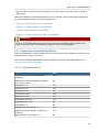
5.3. Minimum System Requirements ..................................................................................
5.3.1. Management Server, Database, and Storage System Requirements ...................
5.3.2. Host/Hypervisor System Requirements .............................................................
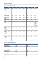
5.3.3. Hypervisor Compatibility Matrix .........................................................................
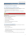
5.4. Management Server Installation ..................................................................................
5.4.1. Management Server Installation Overview .........................................................
5.4.2. Prepare the Operating System .........................................................................
5.4.3. Install the Management Server on the First Host ...............................................
5.4.4. Install and Configure the Database ...................................................................
5.4.5. About Password and Key Encryption ................................................................
5.4.6. Changing the Default Password Encryption .......................................................
5.4.7. Prepare NFS Shares .......................................................................................
5.4.8. Prepare and Start Additional Management Servers ............................................
5.4.9. Management Server Load Balancing ................................................................
5.4.10. Prepare the System VM Template ..................................................................
5.4.11. Installation Complete! Next Steps ...................................................................
43
43
43
44
44
44
45
47
47
47
49
50
54
55
56
59
60
61
62
iii
CloudPlatform (powered by Apache CloudStack) Version 4.2 Installation Guide
5.5. Setting Configuration Parameters ................................................................................
5.5.1. About Configuration Parameters .......................................................................
5.5.2. Setting Global Configuration Parameters ...........................................................
5.5.3. Setting Local Configuration Parameters ............................................................
5.5.4. Granular Global Configuration Parameters ........................................................
62
62
64
64
64
6. User Interface
6.1. Supported Browsers ...................................................................................................
6.2. Log In to the UI .........................................................................................................
6.2.1. End User's UI Overview ...................................................................................
6.2.2. Root Administrator's UI Overview .....................................................................
6.2.3. Logging In as the Root Administrator ................................................................
6.2.4. Changing the Root Password ...........................................................................
6.3. Using SSH Keys for Authentication .............................................................................
6.3.1. Creating an Instance from a Template that Supports SSH Keys ..........................
6.3.2. Creating the SSH Keypair ................................................................................
6.3.3. Creating an Instance ........................................................................................
6.3.4. Logging In Using the SSH Keypair ...................................................................
6.3.5. Resetting SSH Keys ........................................................................................
69
69
69
69
70
70
71
71
71
72
73
73
73
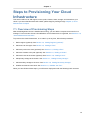
7. Steps to Provisioning Your Cloud Infrastructure
7.1. Overview of Provisioning Steps ...................................................................................
7.2. Adding Regions (optional) ...........................................................................................
7.2.1. The First Region: The Default Region ...............................................................
7.2.2. Adding a Region ..............................................................................................
7.2.3. Adding Third and Subsequent Regions .............................................................
7.2.4. Deleting a Region ............................................................................................
7.3. Adding a Zone ...........................................................................................................
7.3.1. Create a Secondary Storage Mount Point for the New Zone ...............................
7.3.2. Steps to Add a New Zone ................................................................................
7.4. Adding a Pod .............................................................................................................
7.5. Adding a Cluster ........................................................................................................
7.5.1. Add Cluster: KVM or XenServer .......................................................................
7.5.2. Add Cluster: OVM ...........................................................................................
7.5.3. Add Cluster: vSphere .......................................................................................
7.6. Adding a Host ............................................................................................................
7.6.1. Adding a Host (XenServer, KVM, or OVM) ........................................................
7.6.2. Adding a Host (vSphere) ..................................................................................
7.7. Adding Primary Storage ..............................................................................................
7.8. Adding Secondary Storage .........................................................................................
7.8.1. Adding an NFS Secondary Staging Store for Each Zone ....................................
7.9. Initialize and Test .......................................................................................................
75
75
76
76
76
77
78
79
79
79
88
89
89
89
90
93
93
95
95
96
97
98
8. Installing XenServer for CloudPlatform
8.1. System Requirements for XenServer Hosts ................................................................
8.2. XenServer Installation Steps .....................................................................................
8.3. Configure XenServer dom0 Memory ..........................................................................
8.4. Username and Password ..........................................................................................
8.5. Time Synchronization ...............................................................................................
8.6. Licensing ..................................................................................................................
8.6.1. Getting and Deploying a License ....................................................................
8.7. Install CloudPlatform XenServer Support Package (CSP) ............................................
8.8. Primary Storage Setup for XenServer ........................................................................
8.9. iSCSI Multipath Setup for XenServer (Optional) ..........................................................
8.10. Physical Networking Setup for XenServer ................................................................
iv
101
101
102
102
102
102
103
103
103
104
105
106
8.10.1. Configuring Public Network with a Dedicated NIC for XenServer (Optional) .......
8.10.2. Configuring Multiple Guest Networks for XenServer (Optional) ........................
8.10.3. Separate Storage Network for XenServer (Optional) .......................................
8.10.4. NIC Bonding for XenServer (Optional) ...........................................................
106
106
107
107
9. Installing KVM for CloudPlatform
9.1. System Requirements for KVM Hypervisor Hosts .......................................................
9.1.1. Supported Operating Systems for KVM Hosts ..................................................
9.1.2. System Requirements for KVM Hosts .............................................................
9.2. Install and configure the Agent ..................................................................................
9.3. Installing the CloudPlatform Agent on a KVM Host .....................................................
9.4. Physical Network Configuration for KVM ....................................................................
9.5. Time Synchronization for KVM Hosts .........................................................................
9.6. Primary Storage Setup for KVM (Optional) .................................................................
111
111
111
111
112
112
113
114
114
10. Installing VMware for CloudPlatform
10.1. System Requirements for vSphere Hosts .................................................................
10.1.1. Software requirements .................................................................................
10.1.2. Hardware requirements ................................................................................
10.1.3. vCenter Server requirements: .......................................................................
10.1.4. Other requirements: .....................................................................................
10.2. Preparation Checklist for VMware ............................................................................
10.2.1. vCenter Checklist .........................................................................................
10.2.2. Networking Checklist for VMware ..................................................................
10.3. vSphere Installation Steps .......................................................................................
10.4. ESXi Host setup .....................................................................................................
10.5. Physical Host Networking ........................................................................................
10.5.1. Configure Virtual Switch ...............................................................................
10.5.2. Configure vCenter Management Network ......................................................
10.5.3. Configure NIC Bonding for vSphere ..............................................................
10.6. Configuring a vSphere Cluster with Nexus 1000v Virtual Switch .................................
10.6.1. About Cisco Nexus 1000v Distributed Virtual Switch .......................................
10.6.2. Prerequisites and Guidelines ........................................................................
10.6.3. Nexus 1000v Virtual Switch Preconfiguration .................................................
10.6.4. Enabling Nexus Virtual Switch in CloudPlatform .............................................
10.6.5. Configuring Nexus 1000v Virtual Switch in CloudPlatform ...............................
10.6.6. Removing Nexus Virtual Switch ....................................................................
10.6.7. Configuring a VMware Datacenter with VMware Distributed Virtual Switch ........
10.7. Storage Preparation for vSphere (iSCSI only) ...........................................................
10.7.1. Enable iSCSI initiator for ESXi hosts .............................................................
10.7.2. Add iSCSI target ..........................................................................................
10.7.3. Create an iSCSI datastore ............................................................................
10.7.4. Multipathing for vSphere (Optional) ...............................................................
10.8. Add Hosts or Configure Clusters (vSphere) ..............................................................
117
117
117
117
118
118
119
119
119
120
120
120
120
121
121
122
122
122
123
126
126
127
127
132
132
132
133
133
133
11. Bare Metal Installation
11.1. Bare Metal Host System Requirements ....................................................................
11.2. About Bare Metal Kickstart Installation .....................................................................
11.2.1. Limitations of Kickstart Baremetal Installation .................................................
11.3. Provisioning a Bare Metal Host with Kickstart ...........................................................
11.3.1. Download the Software ................................................................................
11.3.2. Set Up IPMI ................................................................................................
11.3.3. Enable PXE on the Bare Metal Host .............................................................
11.3.4. Install the PXE and DHCP Servers ...............................................................
11.3.5. Set Up a File Server ....................................................................................
135
135
135
136
136
136
136
137
137
138
v
CloudPlatform (powered by Apache CloudStack) Version 4.2 Installation Guide
11.3.6. Create a Bare Metal Image ..........................................................................
11.3.7. Create a Bare Metal Compute Offering .........................................................
11.3.8. Create a Bare Metal Network Offering ...........................................................
11.3.9. Set Up the Security Group Agent (Optional) ..................................................
11.3.10. (Optional) Set Bare Metal Configuration Parameters .....................................
11.3.11. Add a Bare Metal Zone ..............................................................................
11.3.12. Add a Bare Metal Cluster ...........................................................................
11.3.13. Add a Bare Metal Host ...............................................................................
11.3.14. Add the PXE Server and DHCP Server to Your Deployment .........................
11.3.15. Create a Bare Metal Template ....................................................................
11.3.16. Provision a Bare Metal Instance ..................................................................
11.3.17. Test Bare Metal Installation ........................................................................
11.3.18. Example CentOS 6.x Kickstart File ..............................................................
11.3.19. Example Fedora 17 Kickstart File ................................................................
11.3.20. Example Ubuntu 12.04 Kickstart File ...........................................................
11.4. Using Cisco UCS as Bare Metal Host CloudPlatform ................................................
11.4.1. Registering a UCS Manager .........................................................................
11.4.2. Associating a Profile with a UCS Blade .........................................................
11.4.3. Disassociating a Profile from a UCS Blade ....................................................
140
140
141
141
143
143
144
144
145
146
147
147
147
148
149
151
151
152
153
12. Installing Oracle VM (OVM) for CloudPlatform
12.1. System Requirements for OVM Hosts ......................................................................
12.2. OVM Installation Overview ......................................................................................
12.3. Installing OVM on the Host(s) .................................................................................
12.4. Primary Storage Setup for OVM ..............................................................................
12.5. Set Up Host(s) for System VMs ...............................................................................
155
155
155
155
156
156
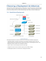
13. Choosing a Deployment Architecture
13.1. Small-Scale Deployment .........................................................................................
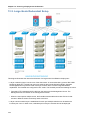
13.2. Large-Scale Redundant Setup .................................................................................
13.3. Separate Storage Network ......................................................................................
13.4. Multi-Node Management Server ..............................................................................
13.5. Multi-Site Deployment .............................................................................................
157
157
158
159
159
159
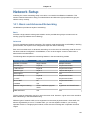
14. Network Setup
14.1. Basic and Advanced Networking .............................................................................
14.2. VLAN Allocation Example .......................................................................................
14.3. Example Hardware Configuration .............................................................................
14.3.1. Dell 62xx .....................................................................................................
14.3.2. Cisco 3750 ..................................................................................................
14.4. Layer-2 Switch .......................................................................................................
14.4.1. Dell 62xx .....................................................................................................
14.4.2. Cisco 3750 ..................................................................................................
14.5. Hardware Firewall ...................................................................................................
14.5.1. Generic Firewall Provisions ..........................................................................
14.5.2. External Guest Firewall Integration for Juniper SRX (Optional) ........................
14.5.3. External Guest Firewall Integration for Cisco VNMC (Optional) ........................
14.6. External Guest Load Balancer Integration (Optional) .................................................
14.7. Topology Requirements ..........................................................................................
14.7.1. Security Requirements .................................................................................
14.7.2. Runtime Internal Communications Requirements ...........................................
14.7.3. Storage Network Topology Requirements ......................................................
14.7.4. External Firewall Topology Requirements ......................................................
14.7.5. Advanced Zone Topology Requirements .......................................................
14.7.6. XenServer Topology Requirements ...............................................................
161
161
162
162
162
163
163
163
164
164
164
165
167
172
173
173
173
174
174
174
174
vi
14.7.7. VMware Topology Requirements ..................................................................
14.7.8. KVM Topology Requirements .......................................................................
14.8. Guest Network Usage Integration for Traffic Sentinel ................................................
14.9. Setting Zone VLAN and Running VM Maximums ......................................................
174
174
174
175
15. Amazon Web Service Interface
15.1. Amazon Web Services EC2 Compatible Interface .....................................................
15.2. System Requirements .............................................................................................
15.3. Enabling the AWS API Compatible Interface ............................................................
15.4. AWS API User Setup Steps (SOAP Only) ................................................................
15.4.1. AWS API User Registration ..........................................................................
15.4.2. AWS API Command-Line Tools Setup ..........................................................
15.5. Supported AWS API Calls .......................................................................................
177
177
177
177
178
178
179
179
16. Additional Installation Options
16.1. Installing the Usage Server (Optional) ......................................................................
16.1.1. Requirements for Installing the Usage Server ................................................
16.1.2. Steps to Install the Usage Server ..................................................................
16.2. SSL (Optional) ........................................................................................................
16.3. Database Replication (Optional) ..............................................................................
16.3.1. Failover .......................................................................................................
183
183
183
183
183
184
186
vii
viii
Chapter 1.
Getting More Information and Help
1.1. Additional Documentation Available
The following guides are available:
• Installation Guide — Covers initial installation of CloudPlatform. It aims to cover in full detail all the
steps and requirements to obtain a functioning cloud deployment.
At times, this guide mentions additional topics in the context of installation tasks, but does not
give full details on every topic. Additional details on many of these topics can be found in the
CloudPlatform Administration Guide. For example, security groups, firewall and load balancing
rules, IP address allocation, and virtual routers are covered in more detail in the Administration
Guide.
• Administration Guide — Discusses how to set up services for the end users of your cloud. Also
covers ongoing runtime management and maintenance. This guide discusses topics like domains,
accounts, service offerings, projects, guest networks, administrator alerts, virtual machines, storage,
and measuring resource usage.
• Developer's Guide — How to use the API to interact with CloudPlatform programmatically.
1.2. Citrix Knowledge Center
Troubleshooting articles by the Citrix support team are available in the Citrix Knowledge Center, at
1
support.citrix.com/product/cs/ .
1.3. Contacting Support
The support team is available to help customers plan and execute their installations. To contact the
2
support team, log in to the support portal at support.citrix.com/cloudsupport by using the account
credentials you received when you purchased your support contract.
1
2
http://support.citrix.com/product/cs/
http://support.citrix.com/cloudsupport
1
2
Chapter 2.
Concepts
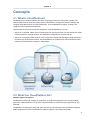
2.1. What Is CloudPlatform?
CloudPlatform is a software platform that pools computing resources to build public, private, and
hybrid Infrastructure as a Service (IaaS) clouds. CloudPlatform manages the network, storage, and
compute nodes that make up a cloud infrastructure. Use CloudPlatform to deploy, manage, and
configure cloud computing environments.
Typical users are service providers and enterprises. With CloudPlatform, you can:
• Set up an on-demand, elastic cloud computing service. Service providers can sell self service virtual
machine instances, storage volumes, and networking configurations over the Internet.
• Set up an on-premise private cloud for use by employees. Rather than managing virtual machines in
the same way as physical machines, with CloudPlatform an enterprise can offer self-service virtual
machines to users without involving IT departments.
2.2. What Can CloudPlatform Do?
Multiple Hypervisor Support
CloudPlatform works with a variety of hypervisors. A single cloud deployment can contain multiple
hypervisor implementations. You have the complete freedom to choose the right hypervisor for your
workload.
CloudPlatform is designed to work with open source Xen and KVM hypervisors as well as enterprisegrade hypervisors such as Citrix XenServer, VMware vSphere, and Oracle VM (OVM).
3
Chapter 2. Concepts
Massively Scalable Infrastructure Management
CloudPlatform can manage tens of thousands of servers installed in multiple geographically distributed
datacenters. The centralized management server scales linearly, eliminating the need for intermediate
cluster-level management servers. No single component failure can cause cloud-wide outage. Periodic
maintenance of the management server can be performed without affecting the functioning of virtual
machines running in the cloud.
Automatic Configuration Management
CloudPlatform automatically configures each guest virtual machine’s networking and storage settings.
CloudPlatform internally manages a pool of virtual appliances to support the cloud itself. These
appliances offer services such as firewalling, routing, DHCP, VPN access, console proxy, storage
access, and storage replication. The extensive use of virtual appliances simplifies the installation,
configuration, and ongoing management of a cloud deployment.
Graphical User Interface
CloudPlatform offers an administrator's Web interface, used for provisioning and managing the cloud,
as well as an end-user's Web interface, used for running VMs and managing VM templates. The UI
can be customized to reflect the desired service provider or enterprise look and feel.
API and Extensibility
CloudPlatform provides an API that gives programmatic access to all the management features
available in the UI. This API enables the creation of command line tools and new user interfaces to
suit particular needs.
The CloudPlatform pluggable allocation architecture allows the creation of new types of allocators for
the selection of storage and hosts.
High Availability
CloudPlatform has a number of features to increase the availability of the system. The Management
Server itself, which is the main controlling software at the heart of CloudPlatform, may be deployed
in a multi-node installation where the servers are load balanced. MySQL may be configured to use
replication to provide for a manual failover in the event of database loss. For the hosts, CloudPlatform
supports NIC bonding and the use of separate networks for storage as well as iSCSI Multipath.
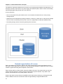
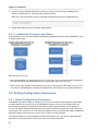
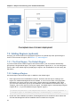
2.3. Deployment Architecture Overview
A CloudPlatform installation consists of two parts: the Management Server and the cloud infrastructure
that it manages. When you set up and manage a CloudPlatform cloud, you provision resources such
as hosts, storage devices, and IP addresses into the Management Server, and the Management
Server manages those resources.
The minimum production installation consists of one machine running the CloudPlatform Management
Server and another machine to act as the cloud infrastructure (in this case, a very simple infrastructure
consisting of one host running hypervisor software). In a trial installation, a single machine can act as
both the Management Server and the hypervisor host (using the KVM hypervisor).
4
Management Server Overview
A more full-featured installation consists of a highly-available multi-node Management Server
installation and up to thousands of hosts using any of several advanced networking setups. For
information about deployment options, see Chapter 13, Choosing a Deployment Architecture.
2.3.1. Management Server Overview
The Management Server is the CloudPlatform software that manages cloud resources. By interacting
with the Management Server through its UI or API, you can configure and manage your cloud
infrastructure.
The Management Server runs on a dedicated server or VM. It controls allocation of virtual machines
to hosts and assigns storage and IP addresses to the virtual machine instances. The Management
Server runs in a Tomcat container and uses a MySQL database for persistence.
The machine where the Management Server runs must meet the system requirements described in
Section 5.3, “Minimum System Requirements”.
The Management Server:
• Provides the web user interface for the administrator and a reference user interface for end users.
• Provides the APIs for CloudPlatform.
• Manages the assignment of guest VMs to particular hosts.
• Manages the assignment of public and private IP addresses to particular accounts.
• Manages the allocation of storage to guests as virtual disks.
• Manages snapshots, templates, and ISO images, possibly replicating them across data centers.
• Provides a single point of configuration for the cloud.
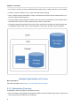
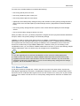
2.3.2. Cloud Infrastructure Overview
The Management Server manages one or more zones (typically, datacenters) containing host
computers where guest virtual machines will run. The cloud infrastructure is organized as follows:
• Region: To increase reliability of the cloud, you can optionally group resources into multiple
geographic regions. A region consists of one or more zones.
• Zone: Typically, a zone is equivalent to a single datacenter. A zone consists of one or more pods
and secondary storage.
5
Chapter 2. Concepts
• Pod: A pod is usually one rack of hardware that includes a layer-2 switch and one or more clusters.
• Cluster: A cluster consists of one or more hosts and primary storage.
• Host: A single compute node within a cluster. The hosts are where the actual cloud services run in
the form of guest virtual machines.
• Primary storage is associated with a cluster, and it can also be provisioned on a zone-wide basis. It
stores the disk volumes for all the VMs running on hosts in that cluster.
• Secondary storage is associated with a zone, and it can also be provisioned as object storage that
is available throughout the cloud. It stores templates, ISO images, and disk volume snapshots.
More Information
For more information, see Chapter 3, Cloud Infrastructure Concepts.
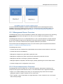
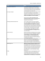
2.3.3. Networking Overview
CloudPlatform offers two types of networking scenario:
• Basic. Provides a single network where guest isolation can be provided through layer-3 means such
as security groups (IP address source filtering).
6
Networking Overview
• Advanced. For more sophisticated network topologies. This network model provides the most
flexibility in defining guest networks and providing guest isolation.
For more details, see Chapter 14, Network Setup.
7
8
Chapter 3.
Cloud Infrastructure Concepts
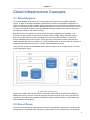
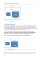
3.1. About Regions
To increase reliability of the cloud, you can optionally group resources into multiple geographic
regions. A region is the largest available organizational unit within a CloudPlatform deployment. A
region is made up of several availability zones, where each zone is equivalent to a datacenter. Each
region is controlled by its own cluster of Management Servers, running in one of the zones. The zones
in a region are typically located in close geographical proximity. Regions are a useful technique for
providing fault tolerance and disaster recovery.
By grouping zones into regions, the cloud can achieve higher availability and scalability. User
accounts can span regions, so that users can deploy VMs in multiple, widely-dispersed regions.
Even if one of the regions becomes unavailable, the services are still available to the end-user
through VMs deployed in another region. And by grouping communities of zones under their own
nearby Management Servers, the latency of communications within the cloud is reduced compared to
managing widely-dispersed zones from a single central Management Server.
Usage records can also be consolidated and tracked at the region level, creating reports or invoices
for each geographic region.
Regions are visible to the end user. When a user starts a guest VM on a particular CloudPlatform
Management Server, the user is implicitly selecting that region for their guest. Users might also be
required to copy their private templates to additional regions to enable creation of guest VMs using
their templates in those regions.
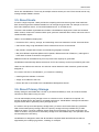
3.2. About Zones
A zone is the second largest organizational unit within a CloudPlatform deployment. A zone typically
corresponds to a single datacenter, although it is permissible to have multiple zones in a datacenter.
9
Chapter 3. Cloud Infrastructure Concepts
The benefit of organizing infrastructure into zones is to provide physical isolation and redundancy. For
example, each zone can have its own power supply and network uplink, and the zones can be widely
separated geographically (though this is not required).
A zone consists of:
• One or more pods. Each pod contains one or more clusters of hosts and one or more primary
storage servers.
• (Optional) If zone-wide primary storage is desired, a zone may contain one or more primary storage
servers, which are shared by all the pods in the zone. (Supported for KVM and VMware hosts)
• Secondary storage, which is shared by all the pods in the zone.
Zones are visible to the end user. When a user starts a guest VM, the user must select a zone for
their guest. Users might also be required to copy their private templates to additional zones to enable
creation of guest VMs using their templates in those zones.
Zones can be public or private. Public zones are visible to all users. This means that any user may
create a guest in that zone. Private zones are reserved for a specific domain. Only users in that
domain or its subdomains may create guests in that zone.
Hosts in the same zone are directly accessible to each other without having to go through a firewall.
Hosts in different zones can access each other through statically configured VPN tunnels.
10
About Pods
For each zone, the administrator must decide the following.
• How many pods to place in a zone.
• How many clusters to place in each pod.
• How many hosts to place in each cluster.
• (Optional) If zone-wide primary storage is being used, decide how many primary storage servers to
place in each zone and total capacity for these storage servers. (Supported for KVM and VMware
hosts)
• How many primary storage servers to place in each cluster and total capacity for these storage
servers.
• How much secondary storage to deploy in a zone.
When you add a new zone, you will be prompted to configure the zone’s physical network and add the
first pod, cluster, host, primary storage, and secondary storage.
(VMware) In order to support zone-wide functions for VMware, CloudPlatform is aware of VMware
Datacenters and can map each Datacenter to a CloudPlatform zone. To enable features like storage
live migration and zone-wide primary storage for VMware hosts, CloudPlatform has to make sure
that a zone contains only a single VMware Datacenter. Therefore, when you are creating a new
CloudPlatform zone, you can select a VMware Datacenter for the zone. If you are provisioning multiple
VMware Datacenters, each one will be set up as a single zone in CloudPlatform.
Note
If you are upgrading from a previous CloudPlatform version, and your existing deployment
contains a zone with clusters from multiple VMware Datacenters, that zone will not be forcibly
migrated to the new model. It will continue to function as before. However, any new zone-wide
operations introduced in CloudPlatform 4.2, such as zone-wide primary storage and live storage
migration, will not be available in that zone.
3.3. About Pods
A pod often represents a single rack. Hosts in the same pod are in the same subnet. A pod is the
third-largest organizational unit within a CloudPlatform deployment. Pods are contained within zones,
and zones can be contained within regions. Each zone can contain one or more pods. A pod consists
of one or more clusters of hosts and one or more primary storage servers. Pods are not visible to the
end user.
11
Chapter 3. Cloud Infrastructure Concepts
3.4. About Clusters
A cluster provides a way to group hosts. To be precise, a cluster is a XenServer server pool, a set
of KVM servers, a set of OVM hosts, or a VMware cluster preconfigured in vCenter. The hosts in a
cluster all have identical hardware, run the same hypervisor, are on the same subnet, and access the
same shared primary storage. Virtual machine instances (VMs) can be live-migrated from one host to
another within the same cluster without interrupting service to the user.
A cluster is the fourth-largest organizational unit within a CloudPlatform deployment. Clusters
are contained within pods, pods are contained within zones, and zones can be contained within
regions. Size of the cluster is only limited by the underlying hypervisor, although the CloudPlatform
recommends you stay below the theoretically allowed maximum cluster size in most cases.
A cluster consists of one or more hosts and one or more primary storage servers.
Even when local storage is used, clusters are still required. In this case, there is just one host per
cluster.
(VMware) If you use VMware hypervisor hosts in your CloudPlatform deployment, each VMware
cluster is managed by a vCenter server. The CloudPlatform administrator must register the vCenter
12
About Hosts
server with CloudPlatform. There may be multiple vCenter servers per zone. Each vCenter server may
manage multiple VMware clusters.
3.5. About Hosts
A host is a single computer. Hosts provide the computing resources that run guest virtual machines.
Each host has hypervisor software installed on it to manage the guest VMs. For example, a host can
be a Citrix XenServer server, a Linux KVM-enabled server, or an ESXi server.
The host is the smallest organizational unit within a CloudPlatform deployment. Hosts are contained
within clusters, clusters are contained within pods, pods are contained within zones, and zones can be
contained within regions.
Hosts in a CloudPlatform deployment:
• Provide the CPU, memory, storage, and networking resources needed to host the virtual machines
• Interconnect using a high bandwidth TCP/IP network and connect to the Internet
• May reside in multiple data centers across different geographic locations
• May have different capacities (different CPU speeds, different amounts of RAM, etc.), although the
hosts within a cluster must all be homogeneous
Additional hosts can be added at any time to provide more capacity for guest VMs.
CloudPlatform automatically detects the amount of CPU and memory resources provided by the hosts.
Hosts are not visible to the end user. An end user cannot determine which host their guest has been
assigned to.
For a host to function in CloudPlatform, you must do the following:
• Install hypervisor software on the host
• Assign an IP address to the host
• Ensure the host is connected to the CloudPlatform Management Server.
3.6. About Primary Storage
Primary storage is associated with a cluster or (in KVM and VMware) a zone, and it stores the disk
volumes for all the VMs running on hosts.
You can add multiple primary storage servers to a cluster or zone. At least one is required. It is
typically located close to the hosts for increased performance. CloudPlatform manages the allocation
of guest virtual disks to particular primary storage devices.
It is useful to set up zone-wide primary storage when you want to avoid extra data copy operations.
With cluster-based primary storage, data in the primary storage is directly available only to VMs
within that cluster. If a VM in a different cluster needs some of the data, it must be copied from one
cluster to another, using the zone's secondary storage as an intermediate step. This operation can be
unnecessarily time-consuming.
CloudPlatform is designed to work with all standards-compliant iSCSI and NFS servers that are
supported by the underlying hypervisor, including, for example:
13
Chapter 3. Cloud Infrastructure Concepts
• Dell EqualLogic™ for iSCSI
• Network Appliances filers for NFS and iSCSI
• Scale Computing for NFS
If you intend to use only local disk for your installation, you can skip adding separate primary storage.
3.7. About Secondary Storage
Secondary storage stores the following:
• Templates — OS images that can be used to boot VMs and can include additional configuration
information, such as installed applications
• ISO images — disc images containing data or bootable media for operating systems
• Disk volume snapshots — saved copies of VM data which can be used for data recovery or to
create new templates
The items in secondary storage are available to all hosts in the scope of the secondary storage, which
may be defined as per zone or per region.
CloudPlatform manages the allocation of guest virtual disks to particular primary storage devices.
To make items in secondary storage available to all hosts throughout the cloud, you can add object
storage in addition to the zone-based NFS Secondary Staging Store. It is not necessary to copy
templates and snapshots from one zone to another, as would be required when using zone NFS
alone. Everything is available everywhere.
Object storage is provided through third-party software such as Amazon Simple Storage Service (S3)
or any other object storage that supports the S3 interface. Additional third party object storages can be
integrated with CloudPlatform by writing plugin software that uses the object storage plugin capability.
CloudPlatform provides some plugins which we have already written for you using this storage plugin
1
capability. The provided plugins are for OpenStack Object Storage (Swift, swift.openstack.org )
and Amazon Simple Storage Service (S3) object storage. The S3 plugin can be used for any object
storage that supports the Amazon S3 interface. When using one of these storage plugins, you
configure Swift or S3 storage for the entire CloudPlatform, then set up the NFS Secondary Staging
Store for each zone. The NFS storage in each zone acts as a staging area through which all templates
and other secondary storage data pass before being forwarded to Swift or S3. The backing object
storage acts as a cloud-wide resource, making templates and other data available to any zone in the
cloud.
There is no hierarchy in the Swift storage, just one Swift container per storage object. Any secondary
storage in the whole cloud can pull a container from Swift at need.
3.8. About Physical Networks
Part of adding a zone is setting up the physical network. One or (in an advanced zone) more physical
networks can be associated with each zone. The network corresponds to a NIC on the hypervisor
host. Each physical network can carry one or more types of network traffic. The choices of traffic
1
http://swift.openstack.org
14
Basic Zone Network Traffic Types
type for each network vary depending on whether you are creating a zone with basic networking or
advanced networking.
A physical network is the actual network hardware and wiring in a zone. A zone can have multiple
physical networks. An administrator can:
• Add/Remove/Update physical networks in a zone
• Configure VLANs on the physical network
• Configure a name so the network can be recognized by hypervisors
• Configure the service providers (firewalls, load balancers, etc.) available on a physical network
• Configure the IP addresses trunked to a physical network
• Specify what type of traffic is carried on the physical network, as well as other properties like
network speed
3.8.1. Basic Zone Network Traffic Types
When basic networking is used, there can be only one physical network in the zone. That physical
network carries the following traffic types:
• Guest. When end users run VMs, they generate guest traffic. The guest VMs communicate with
each other over a network that can be referred to as the guest network. Each pod in a basic zone
is a broadcast domain, and therefore each pod has a different IP range for the guest network. The
administrator must configure the IP range for each pod.
• Management. When CloudPlatform’s internal resources communicate with each other, they
generate management traffic. This includes communication between hosts, system VMs (VMs
used by CloudPlatform to perform various tasks in the cloud), and any other component that
communicates directly with the CloudPlatform Management Server. You must configure the IP
range for the system VMs to use.
Note
We strongly recommend the use of separate NICs for management traffic and guest traffic.
• Public. Public traffic is generated when VMs in the cloud access the Internet. Publicly accessible IPs
must be allocated for this purpose. End users can use the CloudPlatform UI to acquire these IPs
to implement NAT between their guest network and the public network, as described in Acquiring
a New IP Address. Public traffic is generated only in EIP-enabled basic zones. For information on
Elastic IP, see About Elastic IP in the Administration Guide.
• Storage. Traffic such as VM templates and snapshots, which is sent between the secondary storage
VM and secondary storage servers. CloudPlatform uses a separate Network Interface Controller
(NIC) named storage NIC for storage network traffic. Use of a storage NIC that always operates on
a high bandwidth network allows fast template and snapshot copying. You must configure the IP
range to use for the storage network.
In a basic network, configuring the physical network is fairly straightforward. In most cases, you only
need to configure one guest network to carry traffic that is generated by guest VMs. If you use a
NetScaler load balancer and enable its elastic IP and elastic load balancing (EIP and ELB) features,
15
Chapter 3. Cloud Infrastructure Concepts
you must also configure a network to carry public traffic. CloudPlatform takes care of presenting the
necessary network configuration steps to you in the UI when you add a new zone.
3.8.2. Basic Zone Guest IP Addresses
When basic networking is used, CloudPlatform will assign IP addresses in the CIDR of the pod to the
guests in that pod. The administrator must add a direct IP range on the pod for this purpose. These
IPs are in the same VLAN as the hosts.
3.8.3. Advanced Zone Network Traffic Types
When advanced networking is used, there can be multiple physical networks in the zone. Each
physical network can carry one or more traffic types, and you need to let CloudPlatform know which
type of network traffic you want each network to carry. The traffic types in an advanced zone are:
• Guest. When end users run VMs, they generate guest traffic. The guest VMs communicate with
each other over a network that can be referred to as the guest network. This network can be
isolated or shared. In an isolated guest network, the administrator needs to reserve VLAN ranges to
provide isolation for each CloudPlatform account’s network (potentially a large number of VLANs). In
a shared guest network, all guest VMs share a single network.
• Management. When CloudPlatform’s internal resources communicate with each other, they
generate management traffic. This includes communication between hosts, system VMs (VMs
used by CloudPlatform to perform various tasks in the cloud), and any other component that
communicates directly with the CloudPlatform Management Server. You must configure the IP
range for the system VMs to use.
• Public. Public traffic is generated when VMs in the cloud access the Internet. Publicly accessible IPs
must be allocated for this purpose. End users can use the CloudPlatform UI to acquire these IPs to
implement NAT between their guest network and the public network, as described in “Acquiring a
New IP Address” in the Administration Guide.
• Storage. Traffic such as VM templates and snapshots, which is sent between the secondary storage
VM and secondary storage servers. CloudPlatform uses a separate Network Interface Controller
(NIC) named storage NIC for storage network traffic. Use of a storage NIC that always operates on
a high bandwidth network allows fast template and snapshot copying. You must configure the IP
range to use for the storage network.
These traffic types can each be on a separate physical network, or they can be combined with certain
restrictions. When you use the Add Zone wizard in the UI to create a new zone, you are guided into
making only valid choices.
3.8.4. Advanced Zone Guest IP Addresses
When advanced networking is used, the administrator can create additional networks for use by the
guests. These networks can span the zone and be available to all accounts, or they can be scoped
to a single account, in which case only the named account may create guests that attach to these
networks. The networks are defined by a VLAN ID, IP range, and gateway. The administrator may
provision thousands of these networks if desired. Additionally, the administrator can reserve a part of
the IP address space for non-CloudPlatform VMs and servers (see IP Reservation in Isolated Guest
Networks in the Administrator's Guide).
16
Advanced Zone Public IP Addresses
3.8.5. Advanced Zone Public IP Addresses
When advanced networking is used, the administrator can create additional networks for use by the
guests. These networks can span the zone and be available to all accounts, or they can be scoped
to a single account, in which case only the named account may create guests that attach to these
networks. The networks are defined by a VLAN ID, IP range, and gateway. The administrator may
provision thousands of these networks if desired.
3.8.6. System Reserved IP Addresses
In each zone, you need to configure a range of reserved IP addresses for the management network.
This network carries communication between the CloudPlatform Management Server and various
system VMs, such as Secondary Storage VMs, Console Proxy VMs, and DHCP.
The reserved IP addresses must be unique across the cloud. You cannot, for example, have a host in
one zone which has the same private IP address as a host in another zone.
The hosts in a pod are assigned private IP addresses. These are typically RFC1918 addresses. The
Console Proxy and Secondary Storage system VMs are also allocated private IP addresses in the
CIDR of the pod that they are created in.
Make sure computing servers and Management Servers use IP addresses outside of the System
Reserved IP range. For example, suppose the System Reserved IP range starts at 192.168.154.2 and
ends at 192.168.154.7. CloudPlatform can use .2 to .7 for System VMs. This leaves the rest of the pod
CIDR, from .8 to .254, for the Management Server and hypervisor hosts.
In all zones:
Provide private IPs for the system in each pod and provision them in CloudPlatform.
For KVM and XenServer, the recommended number of private IPs per pod is one per host. If you
expect a pod to grow, add enough private IPs now to accommodate the growth.
In a zone that uses advanced networking:
When advanced networking is being used, the number of private IP addresses available in each pod
varies depending on which hypervisor is running on the nodes in that pod. Citrix XenServer and KVM
use link-local addresses, which in theory provide more than 65,000 private IP addresses within the
address block. As the pod grows over time, this should be more than enough for any reasonable
number of hosts as well as IP addresses for guest virtual routers. VMWare ESXi, by contrast uses
any administrator-specified subnetting scheme, and the typical administrator provides only 255 IPs
per pod. Since these are shared by physical machines, the guest virtual router, and other entities, it is
possible to run out of private IPs when scaling up a pod whose nodes are running ESXi.
To ensure adequate headroom to scale private IP space in an ESXi pod that uses advanced
networking, use one or more of the following techniques:
• Specify a larger CIDR block for the subnet. A subnet mask with a /20 suffix will provide more than
4,000 IP addresses.
• Create multiple pods, each with its own subnet. For example, if you create 10 pods and each pod
has 255 IPs, this will provide 2,550 IP addresses.
For vSphere with advanced networking, we recommend provisioning enough private IPs for your total
number of customers, plus enough for the required CloudPlatform System VMs. Typically, about 10
additional IPs are required for the System VMs. For more information about System VMs, see Working
with System Virtual Machines in the Administrator's Guide.
17
18
Chapter 4.
Upgrade Instructions
4.1. Upgrade from 3.0.x to 4.2
Perform the following to upgrade from version 3.0.0, 3.0.1, 3.0.2, 3.0.3, 3.0.4, 3.0.5, 3.0.6, or 3.0.7 to
version 4.2.
1. If you are upgrading from 3.0.0 or 3.0.1, ensure that you query your IP address usage records and
process them; for example, issue invoices for any usage that you have not yet billed users for.
Starting in 3.0.2, the usage record format for IP addresses is the same as the rest of the usage
types. Instead of a single record with the assignment and release dates, separate records are
generated per aggregation period with start and end dates. After upgrading, any existing IP
address usage records in the old format will no longer be available.
2. While running the 3.0.x system, log in to the UI as root administrator.
3. Using the UI, add a new System VM template for each hypervisor type that is used in your cloud.
In each zone, add a system VM template for each hypervisor used in that zone.
Note
You might notice that the size of the system VM template has increased compared to
previous CloudPlatform versions. This is because the new version of the underlying Debian
template has an increased disk size.
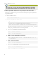
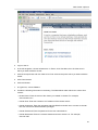
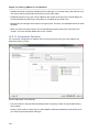
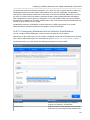
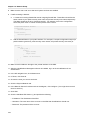
a. In the left navigation bar, click Templates.
b. In Select view, click Templates.
c.
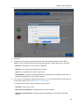
Click Register template.
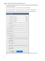
The Register template dialog box is displayed.
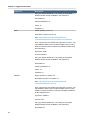
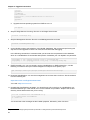
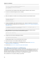
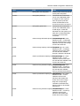
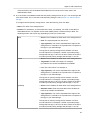
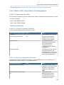
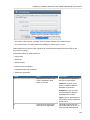
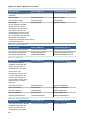
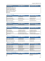
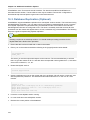
d. In the Register template dialog box, specify the following values depending on the hypervisor
type (do not change these):
Hypervisor
Description
XenServer
Name: systemvm-xenserver-4.2
Description: systemvm-xenserver-4.2
URL: http://download.cloud.com/templates/4.2/
systemvmtemplate-2013-07-12-master-xen.vhd.bz2
Zone: Choose the zone where this hypervisor is used. If your
CloudPlatform deployment includes multiple zones running
XenServer, choose All Zones to make the template available
in all the XenServer zones.
Hypervisor: XenServer
Format: VHD
19
Chapter 4. Upgrade Instructions
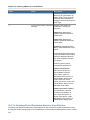
Hypervisor
Description
OS Type: Debian GNU/Linux 7.0 (32-bit) (or the highest
Debian release number available in the dropdown)
Extractable: no
Password Enabled: no
Public: no
Featured: no
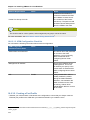
KVM
Name: systemvm-kvm-4.2
Description: systemvm-kvm-4.2
URL: http://download.cloud.com/templates/4.2/
systemvmtemplate-2013-06-12-master-kvm.qcow2.bz2
Zone: Choose the zone where this hypervisor is used. If your
CloudPlatform deployment includes multiple zones running
KVM, choose All Zones to make the template available in all
the KVM zones.
Hypervisor: KVM
Format: QCOW2
OS Type: Debian GNU/Linux 7.0 (32-bit) (or the highest
Debian release number available in the dropdown)
Extractable: no
Password Enabled: no
Public: no
Featured: no
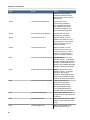
VMware
Name: systemvm-vmware-4.2
Description: systemvm-vmware-4.2
URL: http://download.cloud.com/templates/4.2/
systemvmtemplate-4.2-vh7.ova
Zone: Choose the zone where this hypervisor is used. If your
CloudPlatform deployment includes multiple zones running
VMware, choose All Zones to make the template available in
all the VMware zones.
Hypervisor: VMware
Format: OVA
OS Type: Debian GNU/Linux 7.0 (32-bit) (or the highest
Debian release number available in the dropdown)
Extractable: no
20
Upgrade from 3.0.x to 4.2
Hypervisor
Description
Password Enabled: no
Public: no
Featured: no
e. Watch the screen to be sure that the template downloads successfully and enters the READY
state. Do not proceed until this is successful
f.
If you use more than one type of hypervisor in your cloud, repeat these steps to download the
system VM template for each hypervisor type.
Warning
If you do not repeat the steps for each hypervisor type, the upgrade will fail.
4. (KVM on RHEL 6.0/6.1 only) If your existing CloudPlatform deployment includes one or more
clusters of KVM hosts running RHEL 6.0 or RHEL 6.1, you must first upgrade the operating
system version on those hosts before upgrading CloudPlatform itself.
Run the following commands on every KVM host.
a. Download the CloudPlatform 4.2.0 RHEL 6.3 binaries from https://www.citrix.com/English/ss/
downloads/.
b. Extract the binaries:
# cd /root
# tar xvf CloudPlatform-4.2.0-1-rhel6.3.tar.gz
c.
Create a CloudPlatform 4.2 qemu repo:
# cd CloudPlatform-4.2.0-1-rhel6.3/6.3
# createrepo .
d. Prepare the yum repo for upgrade. Edit the file /etc/yum.repos.d/rhel63.repo. For example:
[upgrade]
name=rhel63
baseurl=url-of-your-rhel6.3-repo
enabled=1
gpgcheck=0
[cloudstack]
name=cloudstack
baseurl=file:///root/CloudPlatform-4.2.0-1-rhel6.3/6.3
enabled=1
gpgcheck=0
e. Upgrade the host operating system from RHEL 6.0 to 6.3:
yum upgrade
21
Chapter 4. Upgrade Instructions
5. Stop all Usage Servers if running. Run this on all Usage Server hosts.
# service cloud-usage stop
6. Stop the Management Servers. Run this on all Management Server hosts.
# service cloud-management stop
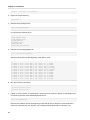
7. On the MySQL master, take a backup of the MySQL databases. We recommend performing this
step even in test upgrades. If there is an issue, this will assist with debugging.
In the following commands, it is assumed that you have set the root password on the database,
which is a CloudPlatform recommended best practice. Substitute your own MySQL root password.
# mysqldump -u root -p<mysql_password> cloud >> cloud-backup.dmp
# mysqldump -u root -p<mysql_password> cloud_usage > cloud-usage-backup.dmp
8. (RHEL/CentOS 5.x) If you are currently running CloudPlatform on RHEL/CentOS 5.x, use the
following command to set up an Extra Packages for Enterprise Linux (EPEL) repo:
rpm -Uvh http://mirror.pnl.gov/epel/5/i386/epel-release-5-4.noarch.rpm
9. Download CloudPlatform 4.2 onto the management server host where it will run. Get the software
from the following link:
https://www.citrix.com/English/ss/downloads/.
1
You need a My Citrix Account .
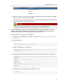
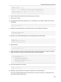
10. Upgrade the CloudPlatform packages. You should have a file in the form of “CloudPlatform-4.2N-OSVERSION.tar.gz”. Untar the file, then run the install.sh script inside it. Replace the file and
directory names below with those you are using:
# tar xzf CloudPlatform-4.2-N-OSVERSION.tar.gz
# cd CloudPlatform-4.2-N-OSVERSION
# ./install.sh
You should see a few messages as the installer prepares, followed by a list of choices.
11. Choose "U" to upgrade the package
>U
You should see some output as the upgrade proceeds, ending with a message like "Complete!
Done."
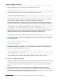
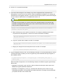
12. If you have made changes to your existing copy of the configuration files components.xml,
db.properties, or server.xml in your previous-version CloudPlatform installation, the changes will
be preserved in the upgrade. However, you need to do the following steps to place these changes
in a new version of the file which is compatible with version 4.2.
1
http://www.citrix.com/lang/English/publicindex.asp?destURL=%2FEnglish%2FmyCitrix%2Findex.asp%3F#
22
Upgrade from 3.0.x to 4.2
Note
How will you know whether you need to do this? If the upgrade output in the previous step
included a message like the following, then some custom content was found in your old file,
and you need to merge the two files:
warning: /etc/cloud.rpmsave/management/components.xml created as /etc/cloudstack/
management/components.xml.rpmnew
a. Make a backup copy of your previous version file. For example: (substitute the file name
components.xml, db.properties, or server.xml in these commands as needed)
# mv /etc/cloudstack/management/components.xml /etc/cloudstack/management/
components.xml-backup
b. Copy the *.rpmnew file to create a new file. For example:
# cp -ap /etc/cloudstack/management/components.xml.rpmnew /etc/cloudstack/management/
components.xml
c.
Merge your changes from the backup file into the new file. For example:
# vi /etc/cloudstack/management/components.xml
13. Repeat steps 8 - 12 on each management server node.
14. Start the first Management Server. Do not start any other Management Server nodes yet.
# service cloudstack-management start
Wait until the databases are upgraded. Ensure that the database upgrade is complete. After
confirmation, start the other Management Servers one at a time by running the same command on
each node.
Note
Failing to restart the Management Server indicates a problem in the upgrade. Restarting the
Management Server without any issues indicates that the upgrade is successfully completed.
15. Start all Usage Servers (if they were running on your previous version). Perform this on each
Usage Server host.
# service cloudstack-usage start
23
Chapter 4. Upgrade Instructions
Note
After upgrade from 3.0.4 to 4.2, if the usage server fails to restart then copy db.properties
from /etc/cloudstack/management to /etc/cloudstack/usage. Then start the Usage Server.
16. (VMware only) If you are upgrading from 3.0.6 or beyond and you have existing clusters,
additional steps are required to update the existing vCenter password for each VMware cluster.
These steps will not affect running guests in the cloud. These steps are required only for clouds
using VMware clusters:
a. Stop the Management Server:
service cloudstack-management stop
b. Perform the following on each VMware cluster:
i.
Encrypt the vCenter password:
java -classpath /usr/share/cloudstack-common/lib/jasypt-1.9.0.jar
org.jasypt.intf.cli.JasyptPBEStringEncryptionCLI encrypt.sh
input=<_your_vCenter_password_> password="`cat /etc/cloudstack/management/key`"
verbose=false
Save the output from this step for later use. You need to add this in the cluster_details and
vmware_data_center tables in place of the existing password.
ii.
Find the ID of the cluster from the cluster_details table:
mysql -u <username> -p<password>
select * from cloud.cluster_details;
iii. Update the existing password with the encrypted one:
update cloud.cluster_details set value = <_ciphertext_from_step_i_> where id =
<_id_from_step_ii_>;
iv. Confirm that the table is updated:
select * from cloud.cluster_details;
v.
Find the ID of the VMware data center that you want to work with:
select * from cloud.vmware_data_center;
vi. Change the existing password to the encrypted one:
24
Upgrade from 3.0.x to 4.2
update cloud.vmware_data_center set password = <_ciphertext_from_step_i_> where
id = <_id_from_step_v_>;
vii. Confirm that the table is updated:
select * from cloud.vmware_data_center;
c.
Start the CloudPlatform Management server
service cloudstack-management start
17. (KVM only) Additional steps are required for each KVM host. These steps will not affect running
guests in the cloud. These steps are required only for clouds using KVM as hosts and only on the
KVM hosts.
Note
After the software upgrade on a KVM machine, the Ctrl+Alt+Del button on the console view of
a VM doesn't work. Use Ctrl+Alt+Insert to log in to the console of the VM.
a. Copy the CloudPlatform 4.2 .tgz download to the host, untar it, and cd into the resulting
directory.
b. Stop the running agent.
# service cloud-agent stop
c.
Update the agent software.
# ./install.sh
d. Choose "U" to update the packages.
e. Edit /etc/cloudstack/agent/agent.properties to change the resource parameter
from com.cloud.agent.resource.computing.LibvirtComputingResource to
com.cloud.hypervisor.kvm.resource.LibvirtComputingResource.
f.
Upgrade all the existing bridge names to new bridge names by running this script:
# cloudstack-agent-upgrade
g. Install a libvirt hook with the following commands:
# mkdir /etc/libvirt/hooks
# cp /usr/share/cloudstack-agent/lib/libvirtqemuhook /etc/libvirt/hooks/qemu
# chmod +x /etc/libvirt/hooks/qemu
h. Restart libvirtd.
25
Chapter 4. Upgrade Instructions
# service libvirtd restart
i.
Start the agent.
# service cloudstack-agent start
18. Log in to the CloudPlatform UI as administrator, and check the status of the hosts. All hosts
should come to Up state (except those that you know to be offline). You may need to wait 20 or 30
minutes, depending on the number of hosts.
Note
Troubleshooting: If login fails, clear your browser cache and reload the page.
Do not proceed to the next step until the hosts show in Up state. If the hosts do not come to the
Up state, contact support.
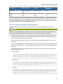
19. If you are upgrading from 3.0.1 or 3.0.2, perform the following:
a. Ensure that the admin port is set to 8096 by using the "integration.api.port" global parameter.
This port is used by the cloudstack-sysvmadm script later in the upgrade procedure. For
information about how to set this parameter, see “Setting Configuration Parameters” in the
Installation Guide.
b. Restart the Management Server.
Note
If you don't want the admin port to remain open, you can set it to null after the upgrade is
done and restart the Management Server.
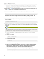
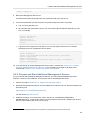
20. Run the following script to stop, then start, all System VMs including Secondary Storage VMs,
Console Proxy VMs, and virtual routers.
a. Run the script once on one management server. Substitute your own IP address of the
MySQL instance, the MySQL user to connect as, and the password to use for that user. In
addition to those parameters, provide the "-a" argument. For example:
# nohup cloudstack-sysvmadm -d 192.168.1.5 -u cloud -p password -a > sysvm.log 2>&1 &
This might take up to an hour or more to run, depending on the number of accounts in the
system.
b. After the script terminates, check the log to verify correct execution:
# tail -f sysvm.log
26
Upgrade from 3.0.x to 4.2
The content should be like the following:
Stopping and starting 1 secondary storage vm(s)...
Done stopping and starting secondary storage vm(s)
Stopping and starting 1 console proxy vm(s)...
Done stopping and starting console proxy vm(s).
Stopping and starting 4 running routing vm(s)...
Done restarting router(s).
c.
If you would like additional confirmation that the new system VM templates were correctly
applied when these system VMs were rebooted, SSH into the System VM and check the
version.
Use one of the following techniques, depending on the hypervisor.
XenServer or KVM:
SSH in by using the link local IP address of the system VM. For example, in the command
below, substitute your own path to the private key used to log in to the system VM and your
own link local IP.
Run the following commands on the XenServer or KVM host on which the system VM is
present:
# ssh -i /root/.ssh/id_rsa.cloud <link-local-ip> -p 3922
# cat /etc/cloudstack-release
The output should be like the following:
Cloudstack Release 4.2 Mon Aug 12 15:10:04 PST 2013
ESXi
SSH in using the private IP address of the system VM. For example, in the command below,
substitute your own path to the private key used to log in to the system VM and your own
private IP.
Run the following commands on the Management Server:
# ssh -i /var/cloudstack/management/.ssh/id_rsa <private-ip> -p 3922
# cat /etc/cloudstack-release
The output should be like the following:
Cloudstack Release 4.2 Mon Sep 24 15:10:04 PST 2012
21. If you want to close the admin port again (recommended in production systems), set
integration.api.port to null. Then restart the Management Server. For information about how to set
integration.api.port, see Section 5.5, “Setting Configuration Parameters”.
22. (XenServer only) If needed, upgrade all Citrix XenServer hypervisor hosts in your cloud to
a version supported by CloudPlatform 4.2 and apply any required hotfixes. Instructions for
upgrading XenServer software and applying hotfixes can be found in Section 4.4, “Upgrading and
Hotfixing XenServer Hypervisor Hosts”.
27
Chapter 4. Upgrade Instructions
23. (VMware only) After upgrade, if you want to change a Standard vSwitch zone to a VMware
dvSwitch Zone, perform the following:
a. Ensure that the Public and Guest traffics are not on the same network as the Management
and Storage traffic.
b. Set vmware.use.dvswitch to true.
c.
Access the physical network for the Public and guest traffic, then change the traffic labels as
given below:
<dvSwitch name>,<VLANID>,<Switch Type>
For example: dvSwitch18,,vmwaredvs
VLANID is optional.
d. Stop the Management server.
e. Start the Management server.
f.
Add the new VMware dvSwitch-enabled cluster to this zone.
24. (VMware only) If your existing cloud includes any deployed data centers, you should set the global
configuration setting vmware.create.full.clone to false. Then restart the Management Server. For
information about how to set vmware.create.full.clone, see Section 5.5, “Setting Configuration
Parameters”. For information about how CloudPlatform supports full and linked clones, see
“Configuring Usage of Linked Clones on VMware” in the CloudPlatform Administration Guide.
Note
Troubleshooting tip: If passwords which you know to be valid appear not to work after upgrade, or
other UI issues are seen, try clearing your browser cache and reloading the UI page.
Note
(VMware only) After upgrade, whenever you add a new VMware cluster to a zone that was
created with a previous version of CloudPlatform, the fields vCenter host, vCenter Username,
vCenter Password, and vCenter Datacenter are required. The Add Cluster dialog in the
CloudPlatform user interface incorrectly shows them as optional, and will allow you to proceed
with adding the cluster even though these important fields are blank. If you do not provide the
values, you will see an error message like "Your host and/or path is wrong. Make sure it's of the
format http://hostname/path".
4.2. Upgrade from 2.2.x to 4.2
1. Ensure that you query your IP address usage records and process them; for example, issue
invoices for any usage that you have not yet billed users for.
28
Upgrade from 2.2.x to 4.2
Starting in 3.0.2, the usage record format for IP addresses is the same as the rest of the usage
types. Instead of a single record with the assignment and release dates, separate records are
generated per aggregation period with start and end dates. After upgrading to 4.2, any existing IP
address usage records in the old format will no longer be available.
2. If you are using version 2.2.0 - 2.2.13, first upgrade to 2.2.14 by using the instructions in the
2
2.2.14 Release Notes .
Note
(KVM only) If KVM hypervisor is used in your cloud, be sure you completed the step to insert
a valid username and password into the host_details table on each KVM node as described
in the 2.2.14 Release Notes. This step is critical, as the database will be encrypted after the
upgrade to 4.2.
3. While running the 2.2.x system (which by this step should be at version 2.2.14 or greater), log in to
the UI as root administrator.
4. Using the UI, add a new System VM template for each hypervisor type that is used in your cloud.
In each zone, add a system VM template for each hypervisor used in that zone.
Note
You might notice that the size of the system VM template has increased compared to
previous CloudPlatform versions. This is because the new version of the underlying Debian
template has an increased disk size.
a. In the left navigation bar, click Templates.
b. In Select view, click Templates.
c.
Click Register template.
The Register template dialog box is displayed.
d. In the Register template dialog box, specify the following values depending on the hypervisor
type (do not change these):
Hypervisor
Description
XenServer
Name: systemvm-xenserver-4.2
Description: systemvm-xenserver-4.2
URL: http://download.cloud.com/templates/4.2/
systemvmtemplate-2013-07-12-master-xen.vhd.bz2
2
http://download.cloud.com/releases/2.2.0/CloudStack2.2.14ReleaseNotes.pdf
29
Chapter 4. Upgrade Instructions
Hypervisor
Description
Zone: Choose the zone where this hypervisor is used. If your
CloudPlatform deployment includes multiple zones running
XenServer, choose All Zones to make the template available
in all the XenServer zones.
Hypervisor: XenServer
Format: VHD
OS Type: Debian GNU/Linux 7.0 (32-bit) (or the highest
Debian release number available in the dropdown)
Extractable: no
Password Enabled: no
Public: no
Featured: no
KVM
Name: systemvm-kvm-4.2
Description: systemvm-kvm-4.2
URL: http://download.cloud.com/templates/4.2/
systemvmtemplate-2013-06-12-master-kvm.qcow2.bz2
Zone: Choose the zone where this hypervisor is used. If your
CloudPlatform deployment includes multiple zones running
KVM, choose All Zones to make the template available in all
the KVM zones.
Hypervisor: KVM
Format: QCOW2
OS Type: Debian GNU/Linux 7.0 (32-bit) (or the highest
Debian release number available in the dropdown)
Extractable: no
Password Enabled: no
Public: no
Featured: no
VMware
Name: systemvm-vmware-4.2
Description: systemvm-vmware-4.2
URL: http://download.cloud.com/templates/4.2/
systemvmtemplate-4.2-vh7.ova
Zone: Choose the zone where this hypervisor is used. If your
CloudPlatform deployment includes multiple zones running
30
Upgrade from 2.2.x to 4.2
Hypervisor
Description
VMware, choose All Zones to make the template available in
all the VMware zones.
Hypervisor: VMware
Format: OVA
OS Type: Debian GNU/Linux 7.0 (32-bit) (or the highest
Debian release number available in the dropdown)
Extractable: no
Password Enabled: no
Public: no
Featured: no
e. Watch the screen to be sure that the template downloads successfully and enters the READY
state. Do not proceed until this is successful
f.
If you use more than one type of hypervisor in your cloud, repeat these steps to download the
system VM template for each hypervisor type.
Warning
If you do not repeat the steps for each hypervisor type, the upgrade will fail.
5. (KVM on RHEL 6.0, 6.1) If your existing CloudPlatform deployment includes one or more clusters
of KVM hosts running RHEL 6.0 or RHEL 6.1, you must first upgrade the operating system version
on those hosts before upgrading CloudPlatform itself.
Run the following commands on every KVM host.
a. Download the CloudPlatform 4.2.0 RHEL 6.3 binaries from https://www.citrix.com/English/ss/
downloads/.
b. Extract the binaries:
# cd /root
# tar xvf CloudPlatform-4.2.0-1-rhel6.3.tar.gz
c.
Create a CloudPlatform 4.2 qemu repo:
# cd CloudPlatform-4.2.0-1-rhel6.3/6.3
# createrepo .
d. Prepare the yum repo for upgrade. Edit the file /etc/yum.repos.d/rhel63.repo. For example:
[upgrade]
name=rhel63
baseurl=url-of-your-rhel6.3-repo
31
Chapter 4. Upgrade Instructions
enabled=1
gpgcheck=0
[cloudstack]
name=cloudstack
baseurl=file:///root/CloudPlatform-4.2.0-1-rhel6.3/6.3
enabled=1
gpgcheck=0
e. Upgrade the host operating system from RHEL 6.0 to 6.3:
yum upgrade
6. Stop all Usage Servers if running. Run this on all Usage Server hosts.
# service cloud-usage stop
7. Stop the Management Servers. Run this on all Management Server hosts.
# service cloud-management stop
8. On the MySQL master, take a backup of the MySQL databases. We recommend performing this
step even in test upgrades. If there is an issue, this will assist with debugging.
In the following commands, it is assumed that you have set the root password on the database,
which is a CloudPlatform recommended best practice. Substitute your own MySQL root password.
# mysqldump -u root -p<mysql_password> cloud >> cloud-backup.dmp
# mysqldump -u root -p<mysql_password> cloud_usage > cloud-usage-backup.dmp
9. (RHEL/CentOS 5.x) If you are currently running CloudPlatform on RHEL/CentOS 5.x, use the
following command to set up an Extra Packages for Enterprise Linux (EPEL) repo:
rpm -Uvh http://mirror.pnl.gov/epel/5/i386/epel-release-5-4.noarch.rpm
10. Download CloudPlatform 4.2 onto the management server host where it will run. Get the software
from the following link:
https://www.citrix.com/English/ss/downloads/
3
You need a My Citrix Account .
11. Upgrade the CloudPlatform packages. You should have a file in the form of “CloudPlatform-4.2N-OSVERSION.tar.gz”. Untar the file, then run the install.sh script inside it. Replace the file and
directory names below with those you are using:
# tar xzf CloudPlatform-4.2-N-OSVERSION.tar.gz
# cd CloudPlatform-4.2-N-OSVERSION
# ./install.sh
You should see a few messages as the installer prepares, followed by a list of choices.
3
http://www.citrix.com/lang/English/publicindex.asp?destURL=%2FEnglish%2FmyCitrix%2Findex.asp%3F#
32
Upgrade from 2.2.x to 4.2
12. Choose "U" to upgrade the package.
> U
13. If you have made changes to your existing copy of the configuration files components.xml,
db.properties, or server.xml in your previous-version CloudPlatform installation, the changes will
be preserved in the upgrade. However, you need to do the following steps to place these changes
in a new version of the file which is compatible with version 4.2.
Note
How will you know whether you need to do this? If the upgrade output in the previous step
included a message like the following, then some custom content was found in your old file,
and you need to merge the two files:
warning: /etc/cloud.rpmsave/management/components.xml created as /etc/cloudstack/
management/components.xml.rpmnew
a. Make a backup copy of your previous version file. For example: (substitute the file name
components.xml, db.properties, or server.xml in these commands as needed)
# mv /etc/cloudstack/management/components.xml /etc/cloudstack/management/
components.xml-backup
b. Copy the *.rpmnew file to create a new file. For example:
# cp -ap /etc/cloudstack/management/components.xml.rpmnew /etc/cloudstack/management/
components.xml
c.
Merge your changes from the backup file into the new file. For example:
# vi /etc/cloudstack/management/components.xml
14. On the management server node, run the following command. It is recommended that you use the
command-line flags to provide your own encryption keys. See Password and Key Encryption in
the Installation Guide.
# cloudstack-setup-encryption -e <encryption_type> -m <management_server_key> -k
<database_key>
When used without arguments, as in the following example, the default encryption type and keys
will be used:
• (Optional) For encryption_type, use file or web to indicate the technique used to pass in the
database encryption password. Default: file.
• (Optional) For management_server_key, substitute the default key that is used to encrypt
confidential parameters in the properties file. Default: password. It is highly recommended that
you replace this with a more secure value
33
Chapter 4. Upgrade Instructions
• (Optional) For database_key, substitute the default key that is used to encrypt confidential
parameters in the CloudPlatform database. Default: password. It is highly recommended that
you replace this with a more secure value.
15. Repeat steps 9 - 14 on every management server node. If you provided your own encryption key
in step 14, use the same key on all other management servers.
16. Start the first Management Server. Do not start any other Management Server nodes yet.
# service cloudstack-management start
Wait until the databases are upgraded. Ensure that the database upgrade is complete. After
confirmation, start the other Management Servers one at a time by running the same command on
each node.
17. Start all Usage Servers (if they were running on your previous version). Perform this on each
Usage Server host.
# service cloudstack-usage start
18. (KVM only) Additional steps are required for each KVM host. These steps will not affect running
guests in the cloud. These steps are required only for clouds using KVM as hosts and only on the
KVM hosts.
Note
After the software upgrade on a KVM machine, the Ctrl+Alt+Del button on the console view of
a VM doesn't work. Use Ctrl+Alt+Insert to log in to the console of the VM.
a. Copy the CloudPlatform 4.2 .tgz download to the host, untar it, and cd into the resulting
directory.
b. Stop the running agent.
# service cloud-agent stop
c.
Update the agent software.
# ./install.sh
d. Choose "U" to update the packages.
e. Edit /etc/cloudstack/agent/agent.properties to change the resource parameter
from com.cloud.agent.resource.computing.LibvirtComputingResource to
com.cloud.hypervisor.kvm.resource.LibvirtComputingResource.
f.
Upgrade all the existing bridge names to new bridge names by running this script:
# cloudstack-agent-upgrade
34
Upgrade from 2.2.x to 4.2
g. Install a libvirt hook with the following commands:
# mkdir /etc/libvirt/hooks
# cp /usr/share/cloudstack-agent/lib/libvirtqemuhook /etc/libvirt/hooks/qemu
# chmod +x /etc/libvirt/hooks/qemu
h. Restart libvirtd.
# service libvirtd restart
i.
Start the agent.
# service cloudstack-agent start
19. Log in to the CloudPlatform UI as admin, and check the status of the hosts. All hosts should come
to Up state (except those that you know to be offline). You may need to wait 20 or 30 minutes,
depending on the number of hosts.
Do not proceed to the next step until the hosts show in the Up state. If the hosts do not come to
the Up state, contact support.
20. Run the following script to stop, then start, all System VMs including Secondary Storage VMs,
Console Proxy VMs, and virtual routers.
a. Run the command once on one management server. Substitute your own IP address of the
MySQL instance, the MySQL user to connect as, and the password to use for that user. In
addition to those parameters, provide the "-c" and "-r" arguments. For example:
# nohup cloudstack-sysvmadm -d 192.168.1.5 -u cloud -p password -a > sysvm.log 2>&1 &
This might take up to an hour or more to run, depending on the number of accounts in the
system.
b. After the script terminates, check the log to verify correct execution:
# tail -f sysvm.log
The content should be like the following:
Stopping and starting 1 secondary storage vm(s)...
Done stopping and starting secondary storage vm(s)
Stopping and starting 1 console proxy vm(s)...
Done stopping and starting console proxy vm(s).
Stopping and starting 4 running routing vm(s)...
Done restarting router(s).
c.
If you would like additional confirmation that the new system VM templates were correctly
applied when these system VMs were rebooted, SSH into the System VM and check the
version.
Use one of the following techniques, depending on the hypervisor.
35
Chapter 4. Upgrade Instructions
XenServer or KVM:
SSH in by using the link local IP address of the system VM. For example, in the command
below, substitute your own path to the private key used to log in to the system VM and your
own link local IP.
Run the following commands on the XenServer or KVM host on which the system VM is
present:
# ssh -i /root/.ssh/id_rsa.cloud <link-local-ip> -p 3922
# cat /etc/cloudstack-release
The output should be like the following:
Cloudstack Release 4.2 Mon Aug 12 15:10:04 PST 2013
ESXi
SSH in using the private IP address of the system VM. For example, in the command below,
substitute your own path to the private key used to log in to the system VM and your own
private IP.
Run the following commands on the Management Server:
# ssh -i /var/cloudstack/management/.ssh/id_rsa <private-ip> -p 3922
# cat /etc/cloudstack-release
The output should be like the following:
Cloudstack Release 4.2 Mon Aug 12 15:10:04 PST 2012
21. (XenServer only) If needed, upgrade all Citrix XenServer hypervisor hosts in your cloud to
a version supported by CloudPlatform 4.2 and apply any required hotfixes. Instructions for
upgrading and applying hotfixes can be found in Section 4.4, “Upgrading and Hotfixing XenServer
Hypervisor Hosts”.
22. (VMware only) If your existing cloud includes any deployed data centers, you should set the global
configuration setting vmware.create.full.clone to false. Then restart the Management Server. For
information about how to set vmware.create.full.clone, see Section 5.5, “Setting Configuration
Parameters”. For information about how CloudPlatform supports full and linked clones, see
“Configuring Usage of Linked Clones on VMware” in the CloudPlatform Administration Guide.
36
Upgrade from 2.1.x to 4.2
Note
(VMware only) After upgrade, whenever you add a new VMware cluster to a zone that was
created with a previous version of CloudPlatform, the fields vCenter host, vCenter Username,
vCenter Password, and vCenter Datacenter are required. The Add Cluster dialog in the
CloudPlatform user interface incorrectly shows them as optional, and will allow you to proceed
with adding the cluster even though these important fields are blank. If you do not provide the
values, you will see an error message like "Your host and/or path is wrong. Make sure it's of the
format http://hostname/path".
4.3. Upgrade from 2.1.x to 4.2
Direct upgrades from version 2.1.0 - 2.1.10 to 4.2 are not supported. CloudPlatform must first
be upgraded to version 2.2.14. For information on how to upgrade from 2.1.x to 2.2.14, see the
CloudPlatform 2.2.14 Release Notes.
4.4. Upgrading and Hotfixing XenServer Hypervisor Hosts
In CloudPlatform 4.2, you can upgrade XenServer hypervisor host software without having to
disconnect the XenServer cluster. You can upgrade XenServer 5.6 GA, 5.6 FP1, or 5.6 SP2 to any
newer version that is supported by CloudPlatform. The actual upgrade is described in XenServer
documentation, but there are some additional steps you must perform before and after the upgrade.
4.4.1. Upgrading to a New XenServer Version
To upgrade XenServer hosts when running CloudPlatform 4.2:
1. Edit the file /etc/cloudstack/management/environment.properties and add the following line:
manage.xenserver.pool.master=false
2. Restart the Management Server to put the new setting into effect.
# service cloudstack-management start
3. Find the hostname of the master host in your XenServer cluster (pool):
a. Run the following command on any host in the pool, and make a note of the host-uuid of the
master host:
# xe pool-list
b. Now run the following command, and find the host that has a host-uuid that matches the
master host from the previous step. Make a note of this host's hostname. You will need to
input it in a later step.
# xe host-list
4. On CloudPlatform, put the master host into maintenance mode. Use the hostname you discovered
in the previous step.
37
Chapter 4. Upgrade Instructions
Note
In the latest XenServer upgrade procedure, even after putting the master host into
maintenance mode, the master host continues to stay as master.
Any VMs running on this master will be automatically migrated to other hosts, unless there is only
one UP host in the cluster. If there is only one UP host, putting the host into maintenance mode
will stop any VMs running on the host.
5. Disconnect the XenServer cluster from CloudPlatform. It will remain disconnected only long
enough to upgrade one host.
a. Log in to the CloudPlatform UI as root.
b. Navigate to the XenServer cluster, and click Actions – Unmanage.
c.
Watch the cluster status until it shows Unmanaged.
6. Upgrade the XenServer software on the master host:
a. Insert the XenXerver CD.
b. Reboot the host.
c.
Upgrade to the newer version of XenServer. Use the steps in XenServer documentation.
7. Cancel the maintenance mode on the master host.
8. Reconnect the XenServer cluster to CloudPlatform.
a. Log in to the CloudPlatform UI as root.
b. Navigate to the XenServer cluster, and click Actions – Manage.
c.
Watch the status to see that all the hosts come up.
9. Upgrade the slave hosts in the cluster:
a. Put a slave host into maintenance mode.
Wait until all the VMs are migrated to other hosts.
b. Upgrade the XenServer software on the slave.
c.
Cancel maintenance mode for the slave.
d. Repeat steps a through c for each slave host in the XenServer pool.
10. You might need to change the OS type settings for VMs running on the upgraded hosts, if any of
the following apply:
• If you upgraded from XenServer 5.6 GA to XenServer 5.6 SP2, change any VMs that have the
OS type CentOS 5.5 (32-bit), Oracle Enterprise Linux 5.5 (32-bit), or Red Hat Enterprise Linux
5.5 (32-bit) to Other Linux (32-bit). Change any VMs that have the 64-bit versions of these same
OS types to Other Linux (64-bit).
38
Applying Hotfixes to a XenServer Cluster
• If you upgraded from XenServer 5.6 SP2 to XenServer 6.0.2 or higher, change any VMs that
have the OS type CentOS 5.6 (32-bit), CentOS 5.7 (32-bit), Oracle Enterprise Linux 5.6 (32bit), Oracle Enterprise Linux 5.7 (32-bit), Red Hat Enterprise Linux 5.6 (32-bit) , or Red Hat
Enterprise Linux 5.7 (32-bit) to Other Linux (32-bit). Change any VMs that have the 64-bit
versions of these same OS types to Other Linux (64-bit).
• If you upgraded from XenServer 5.6 to XenServer 6.0.2 or higher, do all of the above.
4.4.2. Applying Hotfixes to a XenServer Cluster
1. Edit the file /etc/cloudstack/management/environment.properties and add the following line:
manage.xenserver.pool.master=false
2. Restart the Management Server to put the new setting into effect.
# service cloudstack-management start
3. Find the hostname of the master host in your XenServer cluster (pool):
a. Run the following command on any host in the pool, and make a note of the host-uuid of the
master host:
# xe pool-list
b. Now run the following command, and find the host that has a host-uuid that matches the
master host from the previous step. Make a note of this host's hostname. You will need to
input it in a later step.
# xe host-list
4. On CloudPlatform, put the master host into maintenance mode. Use the hostname you discovered
in the previous step.
Any VMs running on this master will be automatically migrated to other hosts, unless there is only
one UP host in the cluster. If there is only one UP host, putting the host into maintenance mode
will stop any VMs running on the host.
5. Disconnect the XenServer cluster from CloudPlatform. It will remain disconnected only long
enough to hotfix one host.
a. Log in to the CloudPlatform UI as root.
b. Navigate to the XenServer cluster, and click Actions – Unmanage.
c.
Watch the cluster status until it shows Unmanaged.
6. Hotfix the master host:
a. Add the XenServer hot fixes to the master host.
i.
Assign a UUID to the update file:
39
Chapter 4. Upgrade Instructions
xe patch-upload file-name=XS602E015.xsupdate
The command displays the UUID of the update file:
33af688e-d18c-493d-922b-ec51ea23cfe9
ii.
Repeat the xe patch-upload command for all other XenServer updates:
XS602E004.xsupdate, XS602E005.xsupdate.
Take a note of the UUIDs of the update files. The UUIDs are required in the next step.
b. Apply XenServer hot fixes to master host:
xe patch-apply host-uuid=<master uuid> uuid=<hotfix uuid>
c.
Repeat xe patch-apply command for all the hot fixes.
d. Install the required CSP files.
xe-install-supplemental-pack <csp-iso-file>
e. Restart the master host.
7. Cancel the maintenance mode on the master host.
8. Reconnect the XenServer cluster to CloudPlatform.
a. Log in to the CloudPlatform UI as root.
b. Navigate to the XenServer cluster, and click Actions – Manage.
c.
Watch the status to see that all the hosts come up.
9. Hotfix the slave hosts in the cluster:
a. Put a slave host into maintenance mode.
Wait until all the VMs are migrated to other hosts.
b. Apply the XenServer hot fixes to the slave host:
xe patch-apply host-uuid=<master uuid> uuid=<hotfix uuid>
c.
Repeat Step a through b for each slave host in the XenServer pool.
d. Install the required CSP files.
xe-install-supplemental-pack <csp-iso-file>
e. Restart the slave hosts.
Wait until all the slave hosts are up. It might take several minutes for the hosts to come up.
10. Cancel the maintenance mode on the slave hosts.
40
Applying Hotfixes to a XenServer Cluster
11. You might need to change the OS type settings for VMs running on the upgraded hosts, if any of
the following apply:
• If you upgraded from XenServer 5.6 SP2 to XenServer 6.0.2, change any VMs that have the
OS type CentOS 5.6 (32-bit), CentOS 5.7 (32-bit), Oracle Enterprise Linux 5.6 (32-bit), Oracle
Enterprise Linux 5.7 (32-bit), Red Hat Enterprise Linux 5.6 (32-bit) , or Red Hat Enterprise Linux
5.7 (32-bit) to Other Linux (32-bit). Change any VMs that have the 64-bit versions of these same
OS types to Other Linux (64-bit).
• If you upgraded from XenServer 5.6 GA or 5.6 FP1 to XenServer 6.0.2, change any VMs
that have the OS type CentOS 5.5 (32-bit), CentOS 5.6 (32-bit), CentOS 5.7 (32-bit), Oracle
Enterprise Linux 5.5 (32-bit), Oracle Enterprise Linux 5.6 (32-bit), Oracle Enterprise Linux 5.7
(32-bit), Red Hat Enterprise Linux 5.5 (32-bit), Red Hat Enterprise Linux 5.6 (32-bit) , or Red
Hat Enterprise Linux 5.7 (32-bit) to Other Linux (32-bit). Change any VMs that have the 64-bit
versions of these same OS types to Other Linux (64-bit).
41
42
Chapter 5.
Installation
5.1. Who Should Read This
These installation instructions are intended for those who are ready to set up a full production
deployment. If you only need to set up a trial installation, you will probably find more detail than you
need here. Instead, you might want to start with the Trial Installation Guide.
With the following procedures, you can start using the more powerful features of CloudPlatform, such
as advanced VLAN networking, high availability, additional network elements such as load balancers
and firewalls, and support for multiple hypervisors including Citrix XenServer, KVM, and VMware
vSphere.
5.2. Overview of Installation Steps
For anything more than a simple trial installation, you will need guidance for a variety of configuration
choices. It is strongly recommended that you read the following:
• Chapter 13, Choosing a Deployment Architecture
• Section 5.3.3, “Hypervisor Compatibility Matrix”
• Chapter 14, Network Setup
• Storage Setup
• Best Practices
Prepare
1. Make sure you have the required hardware ready
2. (Optional) Fill out the preparation checklists
Install the CloudPlatform software
3. Install the Management Server (choose single-node or multi-node)
4. Log in to the UI
Provision your cloud infrastructure
5. Add a zone. Includes the first pod, cluster, and host
6. Add more pods
7. Add more clusters
8. Add more hosts
9. Add more primary storage
10. Add more secondary storage
Try using the cloud
11. Initialization and testing
43
Chapter 5. Installation
5.3. Minimum System Requirements
5.3.1. Management Server, Database, and Storage System
Requirements
The machines that will run the Management Server and MySQL database must meet the following
requirements. The same machines can also be used to provide primary and secondary storage, such
as via local disk or NFS. The Management Server may be placed on a virtual machine.
• Operating system:
• Preferred: RHEL 6.2 or 6.3 64-bit (https://access.redhat.com/downloads)
• Also supported: RHEL 5.5 64-bit
• It is highly recommended that you purchase a RHEL support license. Citrix support can not be
responsible for helping fix issues with the underlying OS.
• 64-bit x86 CPU (more cores results in better performance)
• 4 GB of memory
• 50 GB of local disk (when secondary storage is on the same machine with the Management Server,
500GB is recommended)
• At least 1 NIC
• Statically allocated IP address
• Fully qualified domain name as returned by the hostname command
• Use the default user file-creation mode mask (umask). The value is 022.
If the value is not 022, several files might not be accessible to the cloud user, which leads to
installation failure.
5.3.2. Host/Hypervisor System Requirements
The host is where the cloud services run in the form of guest virtual machines. Each host is one
machine that meets the following requirements:
• Must support HVM (Intel-VT or AMD-V enabled).
• 64-bit x86 CPU (more cores results in better performance)
• Hardware virtualization support required
• 4 GB of memory
• 36 GB of local disk
• At least 1 NIC
• Latest hotfixes applied to hypervisor software
• When you deploy CloudPlatform, the hypervisor host must not have any VMs already running
44
Hypervisor Compatibility Matrix
• All hosts within a cluster must be homogenous. The CPUs must be of the same type, count, and
feature flags.
Hosts have additional requirements depending on the hypervisor. See the requirements listed at the
top of the Installation section for your chosen hypervisor:
• Chapter 8, Installing XenServer for CloudPlatform
• Chapter 10, Installing VMware for CloudPlatform
• Chapter 9, Installing KVM for CloudPlatform
• Chapter 12, Installing Oracle VM (OVM) for CloudPlatform
Warning
Be sure you fulfill the additional hypervisor requirements and installation steps provided in this
Guide. Hypervisor hosts must be properly prepared to work with CloudPlatform.
5.3.3. Hypervisor Compatibility Matrix
Find your CloudPlatform version number in the top row of the table, then look down the column to see
which hypervisor versions you can use.
You can find an additional presentation of this information on the Citrix Knowledge Base at http://
support.citrix.com/article/CTX134803.
5.3.3.1. CloudPlatform 4.x
4.2.0
XenServer 6.2 with fresh CloudPlatform
installation
Yes
XenServer 6.2 with CloudPlatform upgraded
from previous version
No
XenServer 6.1.0
Yes
XenServer 6.0.2
Yes
XenServer 6.0.0
No
XenServer 5.6 SP2
Yes
XenServer 5.6 FP1
Yes
KVM (RHEL 6.2 or 6.3)
Yes
KVM (RHEL 6.0 or 6.1)
No
KVM (RHEL 5.x)
No
VMware ESX 5 and vCenter 5.1
Yes
VMware ESX 5 and vCenter 5.0 (both 5.0.1
Update B)
Yes
VMware ESX 4.1 and vCenter 4.1
No
45
Chapter 5. Installation
5.3.3.2. CloudPlatform 3.x
3.0.0
3.0.1
3.0.2
3.0.3
3.0.4
3.0.5
3.0.6
3.0.7
XenServer No
5.6
No
No
No
No
No
No
No
XenServer No
5.6 FP1
No
Yes
Yes
Yes
Yes
Yes
Yes
XenServer No
5.6 SP2
No
Yes
Yes
Yes
Yes
Yes
Yes
XenServer No
6.0.0
No
No
No
No
No
No
No
XenServer Yes
6.0.2
Yes
Yes
Yes
Yes
Yes
Yes
Yes
XenServer No
6.1
No
No
No
No
No
Yes
Yes
XenServer No
6.2
No
No
No
No
No
No
Yes
(3.0.7
Patch
C or
greater)
KVM
(RHEL
6.0, 6.1
or 6.2)
Yes
Yes
Yes
Yes
Yes
Yes
Yes
Yes
VMware
ESX
4.1 and
vCenter
4.1
Yes
Yes
Yes
Yes
Yes
Yes
Yes
Yes
VMware
ESX
5 and
vCenter
5
Yes
Yes
Yes
Yes
Yes
Yes
Yes
Yes
5.3.3.3. CloudPlatform 2.x
2.1.x
2.2.x
XenServer 5.6
Yes
Yes
XenServer 5.6 FP1
Yes
Yes
XenServer 5.6 SP2
Yes
Yes
XenServer 6.0.0
No
No
XenServer 6.0.2
No
No
XenServer 6.1
No
No
KVM (RHEL 6.0 or 6.1)
Yes
Yes
VMware ESX 4.1 and vCenter
4.1
Yes
Yes
46
Management Server Installation
VMware ESX 5 and vCenter 5
2.1.x
2.2.x
No
No
5.4. Management Server Installation
5.4.1. Management Server Installation Overview
This section describes installing the Management Server. There are two slightly different installation
flows, depending on how many Management Server nodes will be in your cloud:
• A single Management Server node, with MySQL on the same node.
• Multiple Management Server nodes, with MySQL on a node separate from the Management
Servers.
In either case, each machine must meet the system requirements described in System Requirements.
Warning
For the sake of security, be sure the public Internet can not access port 8096 or port 8250 on the
Management Server.
The procedure for installing the Management Server is:
1. Prepare the Operating System
2. Install the First Management Server
3. Install and Configure the MySQL database
4. Prepare NFS Shares
5. Prepare and Start Additional Management Servers (optional)
6. Prepare the System VM Template
5.4.2. Prepare the Operating System
The OS must be prepared to host the Management Server using the following steps. These steps
must be performed on each Management Server node.
1. Log in to your OS as root.
2. Check for a fully qualified hostname.
# hostname --fqdn
This should return a fully qualified hostname such as "managament1.lab.example.org". If it does
not, edit /etc/hosts so that it does.
3. Set SELinux to be permissive by default.
a. Check to see whether SELinux is installed on your machine. If not, you can skip to step 4.
47
Chapter 5. Installation
In RHEL, SELinux is installed and enabled by default. You can verify this with:
# rpm -qa | grep selinux
b. Set the SELINUX variable in /etc/selinux/config to “permissive”. This ensures that the
permissive setting will be maintained after a system reboot.
# vi /etc/selinux/config
c.
Then set SELinux to permissive starting immediately, without requiring a system reboot.
# setenforce 0
4. Make sure that the machine can reach the Internet.
# ping www.cloudstack.org
5. If you do not have a Red Hat Network account, you need to prepare a local Yum repository.
a. If you are working with a physical host, insert the RHEL installation CD. If you are using a VM,
attach the RHEL ISO.
b. Mount the CDROM to /media.
c.
Create a repo file at /etc/yum.repos.d/rhel6.repo. In the file, insert the following lines:
[rhel]
name=rhel6
baseurl=file:///media
enabled=1
gpgcheck=0
6. Turn on NTP for time synchronization.
Note
NTP is required to synchronize the clocks of the servers in your cloud.
a. Install NTP.
# yum install ntp
b. Edit the NTP configuration file to point to your NTP server.
# vi /etc/ntp.conf
Add one or more server lines in this file with the names of the NTP servers you want to use.
For example:
48
Install the Management Server on the First Host
server
server
server
server
c.
0.xenserver.pool.ntp.org
1.xenserver.pool.ntp.org
2.xenserver.pool.ntp.org
3.xenserver.pool.ntp.org
Restart the NTP client.
# service ntpd restart
d. Make sure NTP will start again upon reboot.
# chkconfig ntpd on
7. Repeat all of these steps on every host where the Management Server will be installed.
8. Continue to Section 5.4.3, “Install the Management Server on the First Host”.
5.4.3. Install the Management Server on the First Host
The first step in installation, whether you are installing the Management Server on one host or many,
is to install the software on a single node.
Note
If you are planning to install the Management Server on multiple nodes for high availability, do not
proceed to the additional nodes yet. That step will come later.
1. Download the CloudStack Management Server onto the host where it will run. Get the software
from the following link.
https://www.citrix.com/English/ss/downloads/.
1
You will need a MyCitrix account .
2. Install the CloudStack packages. You should have a file in the form of “CloudStack-VERSION-NOSVERSION.tar.gz”. Untar the file and then run the install.sh script inside it. Replace the file and
directory names below with those you are using:
# tar xzf CloudStack-VERSION-N-OSVERSION.tar.gz
# cd CloudStack-VERSION-N-OSVERSION
# ./install.sh
You should see a few messages as the installer prepares, followed by a list of choices.
3. Choose M to install the Management Server software.
> M
1
http://www.citrix.com/lang/English/publicindex.asp?destURL=%2FEnglish%2FmyCitrix%2Findex.asp%3F
49
Chapter 5. Installation
4. When the installation is finished, run the following commands to start essential services:
#
#
#
#
service rpcbind start
service nfs start
chkconfig nfs on
chkconfig rpcbind on
5. Continue to Section 5.4.4, “Install and Configure the Database”.
5.4.4. Install and Configure the Database
CloudPlatform uses a MySQL database server to store its data. When you are installing the
Management Server on a single node, you can install the MySQL server on the same node if desired.
When installing the Management Server on multiple nodes, we assume that the MySQL database runs
on a separate node.
5.4.4.1. Install the Database on the Management Server Node
This section describes how to install MySQL on the same machine with the Management Server. This
technique is intended for a simple deployment that has a single Management Server node. If you have
a multi-node Management Server deployment, you will typically use a separate node for MySQL. See
Section 5.4.4.2, “Install the Database on a Separate Node”.
1. If you already have a version of MySQL installed on the Management Server node, make one of
the following choices, depending on what version of MySQL it is. The most recent version tested is
5.1.58.
• If you already have installed MySQL version 5.1.58 or later, skip to step 4.
• If you have installed a version of MySQL earlier than 5.1.58, you can either skip to step 4 or
uninstall MySQL and proceed to step 2 to install a more recent version.
Warning
It is important that you choose the right database version. Never downgrade a MySQL
installation.
2. On the same computer where you installed the Management Server, re-run install.sh.
# ./install.sh
You should see a few messages as the installer prepares, followed by a list of choices.
3. Choose D to install the MySQL server from the distribution’s repo.
> D
Troubleshooting: If you do not see the D option, you already have MySQL installed. Please go
back to step 1.
4. Edit the MySQL configuration (/etc/my.cnf or /etc/mysql/my.cnf, depending on your OS) and
insert the following lines in the [mysqld] section. You can put these lines below the datadir line.
50
Install and Configure the Database
The max_connections parameter should be set to 350 multiplied by the number of Management
Servers you are deploying. This example assumes one Management Server.
innodb_rollback_on_timeout=1
innodb_lock_wait_timeout=600
max_connections=350
log-bin=mysql-bin
binlog-format = 'ROW'
Note
The binlog-format variable is supported in MySQL versions 5.1 and greater. It is not
supported in MySQL 5.0. In some versions of MySQL, an underscore character is used in
place of the hyphen in the variable name. For the exact syntax and spelling of each variable,
consult the documentation for your version of MySQL.
5. Restart the MySQL service, then invoke MySQL as the root user.
# service mysqld restart
# mysql -u root
6. Best Practice: MySQL does not set a root password by default. It is very strongly recommended
that you set a root password as a security precaution. Run the following commands, and
substitute your own desired root password.
mysql> SET PASSWORD = PASSWORD('password');
From now on, start MySQL with mysql -p so it will prompt you for the password.
7. To grant access privileges to remote users, perform the following steps.
a. Run the following commands from the mysql prompt:
mysql> GRANT ALL PRIVILEGES ON *.* TO 'root'@'%' WITH GRANT OPTION;
mysql> exit
b. Restart the MySQL service.
# service mysqld restart
c.
Open the MySQL server port (3306) in the firewall to allow remote clients to connect.
# iptables -I INPUT -p tcp --dport 3306 -j ACCEPT
d. Edit the /etc/sysconfig/iptables file and add the following line at the beginning of the INPUT
chain.
-A INPUT -p tcp --dport 3306 -j ACCEPT
51
Chapter 5. Installation
8. Set up the database. The following command creates the cloud user on the database.
• In dbpassword, specify the password to be assigned to the cloud user. You can choose to
provide no password.
• In deploy-as, specify the username and password of the user deploying the database. In the
following command, it is assumed the root user is deploying the database and creating the
cloud user.
• (Optional) For encryption_type, use file or web to indicate the technique used to pass in the
database encryption password. Default: file. See About Password and Key Encryption.
• (Optional) For management_server_key, substitute the default key that is used to encrypt
confidential parameters in the CloudPlatform properties file. Default: password. It is highly
recommended that you replace this with a more secure value. See About Password and Key
Encryption.
• (Optional) For database_key, substitute the default key that is used to encrypt confidential
parameters in the CloudPlatform database. Default: password. It is highly recommended that
you replace this with a more secure value. See About Password and Key Encryption.
# cloudstack-setup-databases cloud:<dbpassword>@localhost --deploy-as=root:<password> -e
<encryption_type> -m <management_server_key> -k <database_key>
9. Now that the database is set up, you can finish configuring the OS for the Management Server.
This command will set up iptables, sudoers, and start the Management Server.
# cloudstack-setup-management
10. Continue to Section 5.4.7, “Prepare NFS Shares”.
5.4.4.2. Install the Database on a Separate Node
This section describes how to install MySQL on a standalone machine, separate from the
Management Server. This technique is intended for a deployment that includes several Management
Server nodes. If you have a single-node Management Server deployment, you will typically use the
same node for MySQL. See Section 5.4.4.1, “Install the Database on the Management Server Node”.
1. If you already have a version of MySQL installed, make one of the following choices, depending
on what version of MySQL it is. The most recent version tested with CloudPlatform is 5.1.58.
• If you already have installed MySQL version 5.1.58 or later, skip to step 3.
• If you have installed a version of MySQL earlier than 5.1.58, you can either skip to step 3 or
uninstall MySQL and proceed to step 2 to install a more recent version.
Warning
It is important that you choose the right database version. Never downgrade a MySQL
installation that is used with CloudPlatform.
2. Log in as root to your Database Node and run the following commands. If you are going to install a
replica database, then log in to the master.
52
Install and Configure the Database
# yum install mysql-server
# chkconfig --level 35 mysqld on
3. Edit the MySQL configuration (/etc/my.cnf or /etc/mysql/my.cnf, depending on your OS) and
insert the following lines in the [mysqld] section. You can put these lines below the datadir line.
The max_connections parameter should be set to 350 multiplied by the number of Management
Servers you are deploying. This example assumes two Management Servers.
innodb_rollback_on_timeout=1
innodb_lock_wait_timeout=600
max_connections=700
log-bin=mysql-bin
binlog-format = 'ROW'
Note
The binlog-format variable is supported in MySQL versions 5.1 and greater. It is not
supported in MySQL 5.0. In some versions of MySQL, an underscore character is used in
place of the hyphen in the variable name. For the exact syntax and spelling of each variable,
consult the documentation for your version of MySQL.
4. Start the MySQL service, then invoke MySQL as the root user.
# service mysqld start
# mysql -u root
5. MySQL does not set a root password by default. It is very strongly recommended that you set
a root password as a security precaution. Run the following command, and substitute your own
desired root password for <password>. You can answer "Y" to all questions except "Disallow root
login remotely?". Remote root login is required to set up the databases.
mysql> SET PASSWORD = PASSWORD('password');
From now on, start MySQL with mysql -p so it will prompt you for the password.
6. To grant access privileges to remote users, perform the following steps.
a. Run the following command from the mysql prompt, then exit MySQL:
mysql> GRANT ALL PRIVILEGES ON *.* TO ‘root’@’%’ WITH GRANT OPTION;
mysql> exit
b. Restart the MySQL service.
# service mysqld restart
c.
Open the MySQL server port (3306) in the firewall to allow remote clients to connect.
# iptables -I INPUT -p tcp --dport 3306 -j ACCEPT
53
Chapter 5. Installation
d. Edit the /etc/sysconfig/iptables file and add the following lines at the beginning of the INPUT
chain.
-A INPUT -p tcp --dport 3306 -j ACCEPT
7. Return to the root shell on your first Management Server.
8. Set up the database. The following command creates the cloud user on the database.
• In dbpassword, specify the password to be assigned to the cloud user. You can choose to
provide no password.
• In dbhost, provide the hostname or IP address of the database node.
• In deploy-as, specify the username and password of the user deploying the database. For
example, if you originally installed MySQL with user “root” and password “password”, provide -deploy-as=root:password.
• (Optional) For encryption_type, use file or web to indicate the technique used to pass in the
database encryption password. Default: file. See Section 5.4.5, “About Password and Key
Encryption”.
• (Optional) For management_server_key, substitute the default key that is used to encrypt
confidential parameters in the CloudPlatform properties file. Default: password. It is highly
recommended that you replace this with a more secure value. See Section 5.4.5, “About
Password and Key Encryption”.
• (Optional) For database_key, substitute the default key that is used to encrypt confidential
parameters in the CloudPlatform database. Default: password. It is highly recommended
that you replace this with a more secure value. See Section 5.4.5, “About Password and Key
Encryption”.
# cloudstack-setup-databases cloud:<dbpassword>@<dbhost> --deploy-as=root:<password> -e
<encryption_type> -m <management_server_key> -k <database_key>
9. Now run a script that will set up iptables rules and SELinux for use by the Management Server. It
will also chkconfig off and start the Management Server.
# cloudstack-setup-management
10. Continue to Section 5.4.7, “Prepare NFS Shares”.
5.4.5. About Password and Key Encryption
CloudPlatform stores several sensitive passwords and secret keys that are used to provide security.
These values are always automatically encrypted:
• Database secret key
• Database password
• SSH keys
• Compute node root password
54
Changing the Default Password Encryption
• VPN password
• User API secret key
• VNC password
CloudPlatform uses the Java Simplified Encryption (JASYPT) library. The data values are encrypted
and decrypted using a database secret key, which is stored in one of CloudPlatform’s internal
properties files along with the database password. The other encrypted values listed above, such as
SSH keys, are in the CloudPlatform internal database.
Of course, the database secret key itself can not be stored in the open – it must be encrypted. How
then does CloudPlatform read it? A second secret key must be provided from an external source
during Management Server startup. This key can be provided in one of two ways: loaded from a file or
provided by the CloudPlatform administrator. The CloudPlatform database has a configuration setting
that lets it know which of these methods will be used. If the encryption type is set to “file,” the key must
be in a file in a known location. If the encryption type is set to “web,” the administrator runs the utility
com.cloud.utils.crypt.EncryptionSecretKeySender, which relays the key to the Management Server
over a known port.
The encryption type, database secret key, and Management Server secret key are set during
CloudPlatform installation. They are all parameters to the CloudPlatform database setup script
(cloudstack-setup-databases). The default values are file, password, and password. It is, of course,
highly recommended that you change these to more secure keys.
5.4.6. Changing the Default Password Encryption
Passwords are encoded when creating or updating users. The default preferred encoder is SHA256.
It is more secure than MD5 hashing, which was used in CloudPlatform 3.x. If you take no action to
customize password encryption and authentication, SHA256 Salt will be used.
If you prefer a different authentication mechanism, CloudPlatform provides a way for you to determine
the default encoding and authentication mechanism for admin and user logins. Two configurable lists
are provided: userPasswordEncoders and userAuthenticators. userPasswordEncoders allow you
to configure the order of preference for encoding passwords, and userAuthenticator allows you to
configure the order in which authentication schemes are invoked to validate user passwords.
The following method determines what encoding scheme is used to encode the password supplied
during user creation or modification.
When a new user is created, the user password is encoded by using the first valid encoder
loaded as per the sequence specified in the UserPasswordEncoders property in
the ComponentContext.xml or nonossComponentContext.xml files. The order
of authentication schemes is determined by the UserAuthenticators property in
the same files. If Non-OSS components, such as VMware environments, are to be
deployed, modify the UserPasswordEncoders and UserAuthenticators lists in the
nonossComponentContext.xml file. For OSS environments, such as XenServer or KVM, modify
the ComponentContext.xml file. It is recommended to make uniform changes across both the files.
When a new authenticator or encoder is added, you can add them to this list. While doing so, ensure
that the new authenticator or encoder is specified as a bean in both the files. The administrator can
change the ordering of both these properties as desired to change the order of schemes. Modify the
following list properties available in client/tomcatconf/nonossComponentContext.xml.in or
client/tomcatconf/componentContext.xml.in as applicable, to the desired order:
<property name="UserAuthenticators">
<list>
55
Chapter 5. Installation
<ref bean="SHA256SaltedUserAuthenticator"/>
<ref bean="MD5UserAuthenticator"/>
<ref bean="LDAPUserAuthenticator"/>
<ref bean="PlainTextUserAuthenticator"/>
</list>
</property>
<property name="UserPasswordEncoders">
<list>
<ref bean="SHA256SaltedUserAuthenticator"/>
<ref bean="MD5UserAuthenticator"/>
<ref bean="LDAPUserAuthenticator"/>
<ref bean="PlainTextUserAuthenticator"/>
</list>
In the above default ordering, SHA256Salt is used first for UserPasswordEncoders. If the module is
found and encoding returns a valid value, the encoded password is stored in the user table's password
column. If it fails for any reason, the MD5UserAuthenticator will be tried next, and the order continues.
For UserAuthenticators, SHA256Salt authentication is tried first. If it succeeds, the user is logged
into the Management server. If it fails, md5 is tried next, and attempts continues until any of them
succeeds and the user logs in . If none of them works, the user is returned an invalid credential
message.
5.4.7. Prepare NFS Shares
CloudPlatform needs a place to keep primary and secondary storage (see Chapter 3, Cloud
Infrastructure Concepts). Both of these can be NFS shares. This section tells how to set up the NFS
shares before adding the storage to CloudPlatform.
For primary storage, you can use iSCSI instead.
The requirements for primary and secondary storage are described in:
• Section 3.6, “About Primary Storage”
• Section 3.7, “About Secondary Storage”
A production installation typically uses a separate NFS server. See Section 5.4.7.1, “Using a Separate
NFS Server”.
You can also use the Management Server node as the NFS server. This is more typical of a trial
installation, but is technically possible in a larger deployment. See Section 5.4.7.2, “Using the
Management Server As the NFS Server”.
5.4.7.1. Using a Separate NFS Server
This section tells how to set up NFS shares for secondary and (optionally) primary storage on an NFS
server running on a separate node from the Management Server.
The exact commands for the following steps may vary depending on your operating system version.
Warning
(KVM only) Ensure that no volume is already mounted at your NFS mount point.
1. On the storage server, create an NFS share for secondary storage and, if you are using NFS for
primary storage as well, create a second NFS share. For example:
56
Prepare NFS Shares
# mkdir -p /export/primary
# mkdir -p /export/secondary
2. To configure the new directories as NFS exports, edit /etc/exports. Export the NFS share(s) with
rw,async,no_root_squash. For example:
# vi /etc/exports
Insert the following line.
/export
*(rw,async,no_root_squash)
3. Export the /export directory.
# exportfs -a
4. On the management server, create a mount point for secondary storage. For example:
# mkdir -p /mnt/secondary
5. Mount the secondary storage on your Management Server. Replace the example NFS server
name and NFS share paths below with your own.
# mount -t nfs nfsservername:/nfs/share/secondary /mnt/secondary
6. If you are setting up multiple Management Server nodes, continue with Section 5.4.8, “Prepare
and Start Additional Management Servers”. If you are setting up a single-node deployment,
continue with Section 5.4.10, “Prepare the System VM Template”.
5.4.7.2. Using the Management Server As the NFS Server
This section tells how to set up NFS shares for primary and secondary storage on the same node with
the Management Server. This is more typical of a trial installation, but is technically possible in a larger
deployment. It is assumed that you will have less than 16TB of storage on the host.
The exact commands for the following steps may vary depending on your operating system version.
1. On the Management Server host, create two directories that you will use for primary and
secondary storage. For example:
# mkdir -p /export/primary
# mkdir -p /export/secondary
2. To configure the new directories as NFS exports, edit /etc/exports. Export the NFS share(s) with
rw,async,no_root_squash. For example:
# vi /etc/exports
Insert the following line.
57
Chapter 5. Installation
/export
*(rw,async,no_root_squash)
3. Export the /export directory.
# exportfs -a
4. Edit the /etc/sysconfig/nfs file.
# vi /etc/sysconfig/nfs
Uncomment the following lines:
LOCKD_TCPPORT=32803
LOCKD_UDPPORT=32769
MOUNTD_PORT=892
RQUOTAD_PORT=875
STATD_PORT=662
STATD_OUTGOING_PORT=2020
5. Edit the /etc/sysconfig/iptables file.
# vi /etc/sysconfig/iptables
Add the following lines at the beginning of the INPUT chain:
A
A
A
A
A
A
A
A
A
A
A
INPUT
INPUT
INPUT
INPUT
INPUT
INPUT
INPUT
INPUT
INPUT
INPUT
INPUT
-m
-m
-m
-m
-m
-m
-m
-m
-m
-m
-m
state
state
state
state
state
state
state
state
state
state
state
--state
--state
--state
--state
--state
--state
--state
--state
--state
--state
--state
NEW
NEW
NEW
NEW
NEW
NEW
NEW
NEW
NEW
NEW
NEW
-p
-p
-p
-p
-p
-p
-p
-p
-p
-p
-p
udp
tcp
tcp
tcp
udp
tcp
udp
tcp
udp
tcp
udp
--dport
--dport
--dport
--dport
--dport
--dport
--dport
--dport
--dport
--dport
--dport
111 -j ACCEPT
111 -j ACCEPT
2049 -j ACCEPT
32803 -j ACCEPT
32769 -j ACCEPT
892 -j ACCEPT
892 -j ACCEPT
875 -j ACCEPT
875 -j ACCEPT
662 -j ACCEPT
662 -j ACCEPT
6. Run the following commands:
# service iptables restart
# service iptables save
7. If NFS v4 communication is used between client and server, add your domain to /etc/idmapd.conf
on both the hypervisor host and Management Server.
# vi /etc/idmapd.conf
Remove the character # from the beginning of the Domain line in idmapd.conf and replace the
value in the file with your own domain. In the example below, the domain is company.com.
58
Prepare and Start Additional Management Servers
Domain = company.com
8. Reboot the Management Server host.
Two NFS shares called /export/primary and /export/secondary are now set up.
9. It is recommended that you test to be sure the previous steps have been successful.
a. Log in to the hypervisor host.
b. Be sure NFS and rpcbind are running. The commands might be different depending on your
OS. For example:
#
#
#
#
#
c.
service rpcbind start
service nfs start
chkconfig nfs on
chkconfig rpcbind on
reboot
Log back in to the hypervisor host and try to mount the /export directories. For example
(substitute your own management server name):
#
#
#
#
#
#
mkdir /primarymount
mount -t nfs <management-server-name>:/export/primary /primarymount
umount /primarymount
mkdir /secondarymount
mount -t nfs <management-server-name>:/export/secondary /secondarymount
umount /secondarymount
10. If you are setting up multiple Management Server nodes, continue with Section 5.4.8, “Prepare
and Start Additional Management Servers”. If you are setting up a single-node deployment,
continue with Section 5.4.10, “Prepare the System VM Template”.
5.4.8. Prepare and Start Additional Management Servers
For your second and subsequent Management Servers, you will install the Management Server
software, connect it to the database, and set up the OS for the Management Server.
1. Perform the steps in Section 5.4.2, “Prepare the Operating System”.
2. Download the Management Server onto the additional host where it will run. Get the software from
the following link.
https://www.citrix.com/English/ss/downloads/
2
You will need a MyCitrix account .
3. Install the packages. You should have a file in the form of “CloudPlatform-VERSION-NOSVERSION.tar.gz”. Untar the file and then run the install.sh script inside it. Replace the file and
directory names below with those you are using:
2
http://www.citrix.com/lang/English/publicindex.asp?destURL=%2FEnglish%2FmyCitrix%2Findex.asp%3F
59
Chapter 5. Installation
# tar xzf CloudPlatform-VERSION-N-OSVERSION.tar.gz
# cd CloudPlatform-VERSION-N-OSVERSION
# ./install.sh
You should see a few messages as the installer prepares, followed by a list of choices.
4. Choose M to install the Management Server software.
> M
5. When the installation is finished, run the following commands to start essential services:
#
#
#
#
service rpcbind start
service nfs start
chkconfig nfs on
chkconfig rpcbind on
6. Configure the database client. Note the absence of the --deploy-as argument in this case. (For
more details about the arguments to this command, see Section 5.4.4.2, “Install the Database on
a Separate Node”.)
# cloudstack-setup-databases cloud:<dbpassword>@<dbhost> -e <encryption_type> -m
<management_server_key> -k <database_key>
7. (Trial installations only) If you are running the hypervisor on the same machine with the
Management Server, edit /etc/sudoers and add the following line:
Defaults:cloud !requiretty
8. Configure the OS and start the Management Server:
# cloudstack-setup-management
The Management Server on this node should now be running.
9. Repeat these steps on each additional Management Server.
10. Be sure to configure a load balancer for the Management Servers. See Section 5.4.9,
“Management Server Load Balancing”.
11. Continue with Section 5.4.10, “Prepare the System VM Template”.
5.4.9. Management Server Load Balancing
CloudPlatform can use a load balancer to provide a virtual IP for multiple Management Servers. The
administrator is responsible for creating the load balancer rules for the Management Servers. The
application requires persistence or stickiness across multiple sessions. The following chart lists the
ports that should be load balanced and whether or not persistence is required.
Even if persistence is not required, enabling it is permitted.
60
Prepare the System VM Template
Source Port
Destination Port
Protocol
Persistence
Required?
80 or 443
8080 (or 20400 with
AJP)
HTTP (or AJP)
Yes
8250
8250
TCP
Yes
8096
8096
HTTP
No
In addition to above settings, the adminstrator is responsible for setting the 'host' global config value
from the management server IP to load balancer virtual IP address. If the 'host' value is not set to the
VIP for Port 8250 and one of your management servers crashes, the UI is still available but the system
VMs will not be able to contact the management server.
5.4.10. Prepare the System VM Template
Secondary storage must be seeded with a template that is used for CloudPlatform system VMs.
Note
When copying and pasting a command, be sure the command has pasted as a single line before
executing. Some document viewers may introduce unwanted line breaks in copied text.
1. On the Management Server, run one or more of the following cloud-install-sys-tmplt commands
to retrieve and decompress the system VM template. Run the command for each hypervisor type
that you expect end users to run in this Zone.
If your secondary storage mount point is not named /mnt/secondary, substitute your own mount
point name.
If you set the CloudPlatform database encryption type to "web" when you set up the database, you
must now add the parameter -s <management-server-secret-key>. See About Password and Key
Encryption.
This process will require approximately 5 GB of free space on the local file system and up to 30
minutes each time it runs.
• For XenServer:
# /usr/share/cloudstack-common/scripts/storage/secondary/cloud-install-sys-tmplt -m /
mnt/secondary -u http://download.cloud.com/templates/4.2/systemvmtemplate-2013-07-12master-xen.vhd.bz2 -h xenserver -s <optional-management-server-secret-key> -F
• For vSphere:
# /usr/share/cloudstack-common/scripts/storage/secondary/cloud-install-sys-tmplt -m /
mnt/secondary -u http://download.cloud.com/templates/4.2/systemvmtemplate-4.2-vh7.ova h vmware -s <optional-management-server-secret-key> -F
• For KVM:
# /usr/share/cloudstack-common/scripts/storage/secondary/cloud-install-sys-tmplt -m /
mnt/secondary -u http://download.cloud.com/templates/4.2/systemvmtemplate-2013-06-12master-kvm.qcow2.bz2 -h kvm -s <optional-management-server-secret-key> -F
61
Chapter 5. Installation
2. If you are using a separate NFS server, perform this step. If you are using the Management
Server as the NFS server, you MUST NOT perform this step.
When the script has finished, unmount secondary storage and remove the created directory.
# umount /mnt/secondary
# rmdir /mnt/secondary
3. Repeat these steps for each secondary storage server.
5.4.11. Installation Complete! Next Steps
Congratulations! You have now installed CloudPlatform Management Server and the database it uses
to persist system data.
What should you do next?
• Even without adding any cloud infrastructure, you can run the UI to get a feel for what's offered and
how you will interact with CloudPlatform on an ongoing basis. See Log In to the UI.
• When you're ready, add the cloud infrastructure and try running some virtual machines on it, so you
can watch how CloudPlatform manages the infrastructure. See Provision Your Cloud Infrastructure.
5.5. Setting Configuration Parameters
5.5.1. About Configuration Parameters
CloudPlatform provides a variety of settings you can use to set limits, configure features, and enable
or disable features in the cloud. Once your Management Server is running, you might need to set
some of these configuration parameters, depending on what optional features you are setting up.
You can set default values at the global level, which will be in effect throughout the cloud unless you
override them at a lower level. You can make local settings, which will override the global configuration
parameter values, at the level of an account, zone, cluster, or primary storage.
The documentation for each CloudPlatform feature should direct you to the names of the applicable
parameters. The following table shows a few of the more useful parameters.
62
About Configuration Parameters
Field
Value
management.network.cidr
A CIDR that describes the network that the
management CIDRs reside on. This variable
must be set for deployments that use vSphere. It
is recommended to be set for other deployments
as well. Example: 192.168.3.0/24.
xen.setup.multipath
For XenServer nodes, this is a true/false variable
that instructs CloudStack to enable iSCSI
multipath on the XenServer Hosts when they are
added. This defaults to false. Set it to true if you
would like CloudStack to enable multipath.
If this is true for a NFS-based deployment
multipath will still be enabled on the XenServer
host. However, this does not impact NFS
operation and is harmless.
secstorage.allowed.internal.sites
This is used to protect your internal network
from rogue attempts to download arbitrary files
using the template download feature. This is a
comma-separated list of CIDRs. If a requested
URL matches any of these CIDRs the Secondary
Storage VM will use the private network interface
to fetch the URL. Other URLs will go through
the public interface. We suggest you set this
to 1 or 2 hardened internal machines where
you keep your templates. For example, set it to
192.168.1.66/32.
use.local.storage
Determines whether CloudStack will use storage
that is local to the Host for data disks, templates,
and snapshots. By default CloudStack will not
use this storage. You should change this to
true if you want to use local storage and you
understand the reliability and feature drawbacks
to choosing local storage.
host
This is the IP address of the Management
Server. If you are using multiple Management
Servers you should enter a load balanced IP
address that is reachable via the private network.
default.page.size
Maximum number of items per page that can be
returned by a CloudStack API command. The
limit applies at the cloud level and can vary from
cloud to cloud. You can override this with a lower
value on a particular API call by using the page
and page size API command parameters. For
more information, see the Developer's Guide.
Default: 500.
ha.tag
The label you want to use throughout the cloud
to designate certain hosts as dedicated HA
hosts. These hosts will be used only for HAenabled VMs that are restarting due to the failure
of another host. For example, you could set this
63
Chapter 5. Installation
Field
Value
to ha_host. Specify the ha.tag value as a host
tag when you add a new host to the cloud.
5.5.2. Setting Global Configuration Parameters
Use the following steps to set global configuration parameters. These values will be the defaults in
effect throughout your CloudPlatform deployment.
1. Log in to the UI as administrator.
2. In the left navigation bar, click Global Settings.
3. In Select View, choose one of the following:
• Global Settings. This displays a list of the parameters with brief descriptions and current values.
• Hypervisor Capabilities. This displays a list of hypervisor versions with the maximum number of
guests supported for each.
4. Use the search box to narrow down the list to those you are interested in.
5. In the Actions column, click the Edit icon to modify a value. If you are viewing Hypervisor
Capabilities, you must click the name of the hypervisor first to display the editing screen.
5.5.3. Setting Local Configuration Parameters
Use the following steps to set local configuration parameters for an account, zone, cluster, or primary
storage. These values will override the global configuration settings.
1. Log in to the UI as administrator.
2. In the left navigation bar, click Infrastructure or Accounts, depending on where you want to set a
value.
3. Find the name of the particular resource that you want to work with. For example, if you are in
Infrastructure, click View All on the Zones, Clusters, or Primary Storage area.
4. Click the name of the resource where you want to set a limit.
5. Click the Settings tab.
6. Use the search box to narrow down the list to those you are interested in.
7. In the Actions column, click the Edit icon to modify a value.
5.5.4. Granular Global Configuration Parameters
The following global configuration parameters have been made more granular. The parameters are
listed under three different scopes: account, cluster, and zone.
Field
Field
account
remote.access.vpn.client.iprange The range of IPs to be
allocated to remotely access
the VPN clients. The first IP in
the range is used by the VPN
server.
64
Value
Granular Global Configuration Parameters
Field
Field
Value
account
allow.public.user.templates
If false, users will not be able to
create public templates.
account
use.system.public.ips
If true and if an account has
one or more dedicated public
IP ranges, IPs are acquired
from the system pool after
all the IPs dedicated to the
account have been consumed.
account
use.system.guest.vlans
If true and if an account has
one or more dedicated guest
VLAN ranges, VLANs are
allocated from the system pool
after all the VLANs dedicated
to the account have been
consumed.
cluster
cluster.storage.allocated.capacity.notificationthreshold
The percentage, as a value
between 0 and 1, of allocated
storage utilization above which
alerts are sent that the storage
is below the threshold.
cluster
cluster.storage.capacity.notificationthreshold
The percentage, as a value
between 0 and 1, of storage
utilization above which alerts
are sent that the available
storage is below the threshold.
cluster
cluster.cpu.allocated.capacity.notificationthreshold
The percentage, as a value
between 0 and 1, of cpu
utilization above which alerts
are sent that the available CPU
is below the threshold.
cluster
cluster.memory.allocated.capacity.notificationthreshold
The percentage, as a value
between 0 and 1, of memory
utilization above which alerts
are sent that the available
memory is below the threshold.
cluster
cluster.cpu.allocated.capacity.disablethreshold
The percentage, as a value
between 0 and 1, of CPU
utilization above which
allocators will disable that
cluster from further usage.
Keep the corresponding
notification threshold lower
than this value to be notified
beforehand.
cluster
cluster.memory.allocated.capacity.disablethreshold
The percentage, as a value
between 0 and 1, of memory
utilization above which
allocators will disable that
cluster from further usage.
65
Chapter 5. Installation
Field
Field
Value
Keep the corresponding
notification threshold lower
than this value to be notified
beforehand.
cluster
cpu.overprovisioning.factor
Used for CPU overprovisioning calculation;
the available CPU will be
the mathematical product
of actualCpuCapacity and
cpu.overprovisioning.factor.
cluster
mem.overprovisioning.factor
Used for memory overprovisioning calculation.
cluster
vmware.reserve.cpu
Specify whether or not to
reserve CPU when not overprovisioning; In case of CPU
over-provisioning, CPU is
always reserved.
cluster
vmware.reserve.mem
Specify whether or not to
reserve memory when not
over-provisioning; In case of
memory over-provisioning
memory is always reserved.
zone
pool.storage.allocated.capacity.disablethreshold
The percentage, as a value
between 0 and 1, of allocated
storage utilization above which
allocators will disable that pool
because the available allocated
storage is below the threshold.
zone
pool.storage.capacity.disablethreshold
The percentage, as a value
between 0 and 1, of storage
utilization above which
allocators will disable the pool
because the available storage
capacity is below the threshold.
zone
storage.overprovisioning.factor
Used for storage overprovisioning calculation;
available storage will be
the mathematical product
of actualStorageSize and
storage.overprovisioning.factor.
zone
network.throttling.rate
Default data transfer rate in
megabits per second allowed in
a network.
zone
guest.domain.suffix
Default domain name for VMs
inside a virtual networks with a
router.
zone
router.template.xen
Name of the default router
template on Xenserver.
66
Granular Global Configuration Parameters
Field
Field
Value
zone
router.template.kvm
Name of the default router
template on KVM.
zone
router.template.vmware
Name of the default router
template on VMware.
zone
enable.dynamic.scale.vm
Enable or diable dynamically
scaling of a VM.
zone
use.external.dns
Bypass internal DNS, and use
the external DNS1 and DNS2
zone
blacklisted.routes
Routes that are blacklisted
cannot be used for creating
static routes for a VPC Private
Gateway.
67
68
Chapter 6.
User Interface
6.1. Supported Browsers
The CloudPlatform web-based UI is available in the following popular browsers:
• Mozilla Firefox 22 or greater
• Apple Safari, all versions packaged with Mac OS X 10.5 (Leopard) or greater
• Google Chrome, all versions starting from the year 2012
• Microsoft Internet Explorer 9 or greater
6.2. Log In to the UI
CloudPlatform provides a web-based UI that can be used by both administrators and end users. The
appropriate version of the UI is displayed depending on the credentials used to log in.
The URL to log in to CloudPlatform is: (substitute your own management server IP address)
http://<management-server-ip-address>:8080/client
On a fresh Management Server installation, a guided tour splash screen appears. On later visits, you’ll
see a login screen where you specify the following to proceed to your Dashboard:
Username
The user ID of your account. The default username is admin.
Password
The password associated with the user ID. The password for the default username is password.
Domain
If you are a root user, leave this field blank.
If you are a user in the sub-domains, enter the full path to the domain, excluding the root domain.
For example, suppose multiple levels are created under the root domain, such as Comp1/hr. The
users in the Comp1 domain should enter Comp1 in the Domain field, whereas the users in the Comp1/
sales domain should enter Comp1/sales.
For more guidance about the choices that appear when you log in to this UI, see Logging In as the
Root Administrator.
6.2.1. End User's UI Overview
The CloudPlatform UI helps users of cloud infrastructure to view and use their cloud resources,
including virtual machines, templates and ISOs, data volumes and snapshots, guest networks, and IP
addresses. If the user is a member or administrator of one or more CloudPlatform projects, the UI can
provide a project-oriented view.
69
Chapter 6. User Interface
6.2.2. Root Administrator's UI Overview
The CloudPlatform UI helps the CloudPlatform administrator provision, view, and manage the cloud
infrastructure, domains, user accounts, projects, and configuration settings. The first time you start the
UI after a fresh Management Server installation, you can choose to follow a guided tour to provision
your cloud infrastructure. On subsequent logins, the dashboard of the logged-in user appears.
The various links in this screen and the navigation bar on the left provide access to a variety of
administrative functions. The root administrator can also use the UI to perform all the same tasks that
are present in the end-user’s UI.
6.2.3. Logging In as the Root Administrator
After the Management Server software is installed and running, you can run the CloudPlatform user
interface. This UI is there to help you provision, view, and manage your cloud infrastructure.
1. Open your favorite Web browser and go to this URL. Substitute the IP address of your own
Management Server:
http://<management-server-ip-address>:8080/client
On a fresh Management Server installation, a guided tour splash screen appears. On later visits,
you’ll see a login screen where you can enter a user ID and password and proceed to your
Dashboard.
2. If you see the first-time splash screen, choose one of the following.
• Continue with basic setup. Choose this if you're just trying CloudPlatform, and you want
a guided walkthrough of the simplest possible configuration so that you can get started right
away. We'll help you set up a cloud with the following features: a single machine that runs
CloudPlatform software and uses NFS to provide storage; a single machine running VMs under
the XenServer or KVM hypervisor; and a shared public network.
The prompts in this guided tour should give you all the information you need, but if you want just
a bit more detail, you can follow along in the Trial Installation Guide.
• I have used CloudPlatform before. Choose this if you have already gone through a design
phase and planned a more sophisticated deployment, or you are ready to start scaling up a trial
cloud that you set up earlier with the basic setup screens. In the Administrator UI, you can start
using the more powerful features of CloudPlatform, such as advanced VLAN networking, high
availability, additional network elements such as load balancers and firewalls, and support for
multiple hypervisors including Citrix XenServer, KVM, and VMware vSphere.
The root administrator Dashboard appears.
3. You should set a new root administrator password. If you chose basic setup, you’ll be prompted to
create a new password right away. If you chose experienced user, use the steps in Section 6.2.4,
“Changing the Root Password”.
70
Changing the Root Password
Warning
You are logging in as the root administrator. This account manages the CloudPlatform
deployment, including physical infrastructure. The root administrator can modify configuration
settings to change basic functionality, create or delete user accounts, and take many actions that
should be performed only by an authorized person. Please change the default password to a
new, unique password.
6.2.4. Changing the Root Password
During installation and ongoing cloud administration, you will need to log in to the UI as the root
administrator. The root administrator account manages the CloudPlatform deployment, including
physical infrastructure. The root administrator can modify configuration settings to change basic
functionality, create or delete user accounts, and take many actions that should be performed only by
an authorized person. When first installing CloudPlatform, be sure to change the default password to a
new, unique value.
1. Open your favorite Web browser and go to this URL. Substitute the IP address of your own
Management Server:
http://<management-server-ip-address>:8080/client
2. Log in to the UI using the current root user ID and password. The default is admin, password.
3. Click Accounts.
4. Click the admin account name.
5. Click View Users.
6. Click the admin user name.
7.
Click the Change Password button.
8. Type the new password, and click OK.
6.3. Using SSH Keys for Authentication
In addition to the username and password authentication, CloudPlatform supports using SSH keys to
log in to the cloud infrastructure for additional security for your cloud infrastructure. You can use the
createSSHKeyPair API to generate the SSH keys.
Because each cloud user has their own ssh key, one cloud user cannot log in to another cloud user's
instances unless they share their ssh key files. Using a single SSH key pair, you can manage multiple
instances.
6.3.1. Creating an Instance from a Template that Supports SSH
Keys
Perform the following:
1. Create a new instance by using the template provided by CloudPlatform.
71
Chapter 6. User Interface
For more information on creating a new instance, see Creating VMs in the Administration Guide.
2. Download the script file cloud-set-guest-sshkey from the following link:
http://download.cloud.com/templates/4.2/bindir/cloud-set-guest-sshkey.in
3. Copy the file to /etc/init.d.
4. Give the necessary permissions on the script:
chmod +x /etc/init.d/cloud-set-guest-sshkey
5. Run the script while starting up the operating system:
chkconfig --add cloud-set-guest-sshkey
6. Stop the instance.
6.3.2. Creating the SSH Keypair
You must make a call to the createSSHKeyPair api method. You can either use the CloudPlatform
python api library or the curl commands to make the call to the CloudPlatform api.
For example, make a call from the CloudPlatform server to create a SSH keypair called "keypair-doc"
for the admin account in the root domain:
Note
Ensure that you adjust these values to meet your needs. If you are making the API call from a
different server, your URL or port number will be different, and you will need to use the API keys.
1. Run the following curl command:
curl --globoff "http://localhost:8080/?command=createSSHKeyPair&name=keypairdoc&account=admin&domainid=1"
The output is something similar to what is given below:
<?xml version="1.0" encoding="ISO-8859-1"?><createsshkeypairresponse
cloud-stack-version="3.0.0.20120228045507"><keypair><name>keypairdoc</name><fingerprint>f6:77:39:d5:5e:77:02:22:6a:d8:7f:ce:ab:cd:b3:56</
fingerprint><privatekey>-----BEGIN RSA PRIVATE KEY----MIICXQIBAAKBgQCSydmnQ67jP6lNoXdX3noZjQdrMAWNQZ7y5SrEu4wDxplvhYci
dXYBeZVwakDVsU2MLGl/K+wefwefwefwefwefJyKJaogMKn7BperPD6n1wIDAQAB
AoGAdXaJ7uyZKeRDoy6wA0UmF0kSPbMZCR+UTIHNkS/E0/4U+6lhMokmFSHtu
mfDZ1kGGDYhMsdytjDBztljawfawfeawefawfawfawQQDCjEsoRdgkduTy
QpbSGDIa11Jsc+XNDx2fgRinDsxXI/zJYXTKRhSl/LIPHBw/brW8vzxhOlSOrwm7
VvemkkgpAkEAwSeEw394LYZiEVv395ar9MLRVTVLwpo54jC4tsOxQCBlloocK
lYaocpk0yBqqOUSBawfIiDCuLXSdvBo1Xz5ICTM19vgvEp/+kMuECQBzm
nVo8b2Gvyagqt/KEQo8wzH2THghZ1qQ1QRhIeJG2aissEacF6bGB2oZ7Igim5L14
4KR7OeEToyCLC2k+02UCQQCrniSnWKtDVoVqeK/zbB32JhW3Wullv5p5zUEcd
KfEEuzcCUIxtJYTahJ1pvlFkQ8anpuxjSEDp8x/18bq3
-----END RSA PRIVATE KEY----</privatekey></keypair></createsshkeypairresponse>
72
Creating an Instance
2. Copy the key data into a file. The file looks like this:
-----BEGIN RSA PRIVATE KEY----MIICXQIBAAKBgQCSydmnQ67jP6lNoXdX3noZjQdrMAWNQZ7y5SrEu4wDxplvhYci
dXYBeZVwakDVsU2MLGl/K+wefwefwefwefwefJyKJaogMKn7BperPD6n1wIDAQAB
AoGAdXaJ7uyZKeRDoy6wA0UmF0kSPbMZCR+UTIHNkS/E0/4U+6lhMokmFSHtu
mfDZ1kGGDYhMsdytjDBztljawfawfeawefawfawfawQQDCjEsoRdgkduTy
QpbSGDIa11Jsc+XNDx2fgRinDsxXI/zJYXTKRhSl/LIPHBw/brW8vzxhOlSOrwm7
VvemkkgpAkEAwSeEw394LYZiEVv395ar9MLRVTVLwpo54jC4tsOxQCBlloocK
lYaocpk0yBqqOUSBawfIiDCuLXSdvBo1Xz5ICTM19vgvEp/+kMuECQBzm
nVo8b2Gvyagqt/KEQo8wzH2THghZ1qQ1QRhIeJG2aissEacF6bGB2oZ7Igim5L14
4KR7OeEToyCLC2k+02UCQQCrniSnWKtDVoVqeK/zbB32JhW3Wullv5p5zUEcd
KfEEuzcCUIxtJYTahJ1pvlFkQ8anpuxjSEDp8x/18bq3
-----END RSA PRIVATE KEY-----
3. Save the file.
6.3.3. Creating an Instance
Ensure that you use the same SSH key name that you created.
Note
You cannot create the instance by using the GUI at this time and associate the instance with the
newly created SSH keypair.
A sample curl command to create a new instance is:
curl --globoff http://localhost:<port number>/?
command=deployVirtualMachine&zoneId=1&serviceOfferingId=18727021-7556-4110-9322d625b52e0813&templateId=e899c18ace13-4bbf-98a9-625c5026e0b5&securitygroupids=ff03f02f-9e3b-48f8-834d-91b822da40c5&account=admin
\&domainid=1&keypair=keypair-doc
Substitute the template, service offering and security group IDs (if you are using the security group
feature) that are in your cloud environment.
6.3.4. Logging In Using the SSH Keypair
To test your SSH key generation is successful, check whether you can log in to the cloud setup.
For example, from a Linux OS, run:
ssh -i ~/.ssh/keypair-doc <ip address>
The -i parameter directs the ssh client to use a ssh key found at ~/.ssh/keypair-doc.
6.3.5. Resetting SSH Keys
With the API command resetSSHKeyForVirtualMachine, a user can set or reset the SSH keypair
assigned to a virtual machine. A lost or compromised SSH keypair can be changed, and the user
can access the VM by using the new keypair. Just create or register a new keypair, then call
resetSSHKeyForVirtualMachine.
73
74
Chapter 7.
Steps to Provisioning Your Cloud
Infrastructure
This section tells how to add regions, zones, pods, clusters, hosts, storage, and networks to your
cloud. If you are unfamiliar with these entities, please begin by looking through Chapter 3, Cloud
Infrastructure Concepts.
7.1. Overview of Provisioning Steps
After the Management Server is installed and running, you can add the compute resources for it to
manage. For an overview of how a CloudPlatform cloud infrastructure is organized, see Section 2.3.2,
“Cloud Infrastructure Overview”.
To provision the cloud infrastructure, or to scale it up at any time, follow these procedures:
1. Define regions (optional). See Section 7.2, “Adding Regions (optional)”.
2. Add a zone to the region. See Section 7.3, “Adding a Zone”.
3. Add more pods to the zone (optional). See Section 7.4, “Adding a Pod”.
4. Add more clusters to the pod (optional). See Section 7.5, “Adding a Cluster”.
5. Add more hosts to the cluster (optional). See Section 7.6, “Adding a Host”.
6. Add primary storage to the cluster. See Section 7.7, “Adding Primary Storage”.
7. Add secondary storage to the zone. See Section 7.8, “Adding Secondary Storage”.
8. Initialize and test the new cloud. See Section 7.9, “Initialize and Test”.
When you have finished these steps, you will have a deployment with the following basic structure:
75
Chapter 7. Steps to Provisioning Your Cloud Infrastructure
7.2. Adding Regions (optional)
Grouping your cloud resources into geographic regions is an optional step when provisioning the
cloud. For an overview of regions, see Section 3.1, “About Regions”.
7.2.1. The First Region: The Default Region
If you do not take action to define regions, then all the zones in your cloud will be automatically
grouped into a single default region. This region is assigned the region ID of 1. You can change the
name or URL of the default region by displaying the region in the CloudPlatform UI and clicking the
Edit button.
7.2.2. Adding a Region
Use these steps to add a second region in addition to the default region.
1. Each region has its own CloudPlatform instance. Therefore, the first step of creating a new
region is to install the Management Server software, on one or more nodes, in the geographic
area where you want to set up the new region. Use the steps in the Installation guide. When
you come to the step where you set up the database, use the additional command-line flag -r
<region_id> to set a region ID for the new region. The default region is automatically assigned
a region ID of 1, so your first additional region might be region 2.
cloudstack-setup-databases cloud:<dbpassword>@localhost --deploy-as=root:<password> -e
<encryption_type> -m <management_server_key> -k <database_key> -r <region_id>
2. By the end of the installation procedure, the Management Server should have been started. Be
sure that the Management Server installation was successful and complete.
76
Adding Third and Subsequent Regions
3. Now add the new region to region 1 in CloudPlatform.
a. Log in to CloudPlatform in the first region as root administrator (that is, log in to
<region.1.IP.address>:8080/client).
b. In the left navigation bar, click Regions.
c.
Click Add Region. In the dialog, fill in the following fields:
• ID. A unique identifying number. Use the same number you set in the database during
Management Server installation in the new region; for example, 2.
• Name. Give the new region a descriptive name.
• Endpoint. The URL where you can log in to the Management Server in the new region. This
has the format <region.2.IP.address>:8080/client.
4. Now perform the same procedure in reverse. Log in to region 2, and add region 1.
5. Copy the account, user, and domain tables from the region 1 database to the region 2 database.
In the following commands, it is assumed that you have set the root password on the database,
which is a CloudPlatform recommended best practice. Substitute your own MySQL root password.
a. First, run this command to copy the contents of the database:
# mysqldump -u root -p<mysql_password> -h <region1_db_host> cloud account user domain
> region1.sql
b. Then run this command to put the data onto the region 2 database:
# mysql -u root -p<mysql_password> -h <region2_db_host> cloud < region1.sql
6. Remove project accounts. Run these commands on the region 2 database:
mysql> delete from account where type = 5;
7. Set the default zone as null:
mysql> update account set default_zone_id = null;
8. Restart the Management Servers in region 2.
7.2.3. Adding Third and Subsequent Regions
To add the third region, and subsequent additional regions, the steps are similar to those for adding
the second region. However, you must repeat certain steps additional times for each additional region:
1. Install CloudPlatform in each additional region. Set the region ID for each region during the
database setup step.
cloudstack-setup-databases cloud:<dbpassword>@localhost --deploy-as=root:<password> -e
<encryption_type> -m <management_server_key> -k <database_key> -r <region_id>
77
Chapter 7. Steps to Provisioning Your Cloud Infrastructure
2. Once the Management Server is running, add your new region to all existing regions by repeatedly
using the Add Region button in the UI. For example, if you were adding region 3:
a. Log in to CloudPlatform in the first region as root administrator (that is, log in to
<region.1.IP.address>:8080/client), and add a region with ID 3, the name of region 3, and the
endpoint <region.3.IP.address>:8080/client.
b. Log in to CloudPlatform in the second region as root administrator (that is, log in to
<region.2.IP.address>:8080/client), and add a region with ID 3, the name of region 3, and the
endpoint <region.3.IP.address>:8080/client.
3. Repeat the procedure in reverse to add all existing regions to the new region. For example, for the
third region, add the other two existing regions:
a. Log in to CloudPlatform in the third region as root administrator (that is, log in to
<region.3.IP.address>:8080/client).
b. Add a region with ID 1, the name of region 1, and the endpoint <region.1.IP.address>:8080/
client.
c.
Add a region with ID 2, the name of region 2, and the endpoint <region.2.IP.address>:8080/
client.
4. Copy the account, user, and domain tables from any existing region's database to the new
region's database.
In the following commands, it is assumed that you have set the root password on the database,
which is a CloudPlatform recommended best practice. Substitute your own MySQL root password.
a. First, run this command to copy the contents of the database:
# mysqldump -u root -p<mysql_password> -h <region1_db_host> cloud account user domain
> region1.sql
b. Then run this command to put the data onto the new region's database. For example, for
region 3:
# mysql -u root -p<mysql_password> -h <region3_db_host> cloud < region1.sql
5. Remove project accounts. Run these commands on the region 3 database:
mysql> delete from account where type = 5;
6. Set the default zone as null:
mysql> update account set default_zone_id = null;
7. Restart the Management Servers in the new region.
7.2.4. Deleting a Region
Log in to each of the other regions, navigate to the one you want to delete, and click Remove Region.
For example, to remove the third region in a 3-region cloud:
1. Log in to <region.1.IP.address>:8080/client.
78
Adding a Zone
2. In the left navigation bar, click Regions.
3. Click the name of the region you want to delete.
4. Click the Remove Region button.
5. Repeat these steps for <region.2.IP.address>:8080/client.
7.3. Adding a Zone
Adding a zone consists of three phases:
• Create a mount point for secondary storage on the Management Server.
• Seed the system VM template on the secondary storage.
• Add the zone.
7.3.1. Create a Secondary Storage Mount Point for the New Zone
To be sure the most up-to-date system VMs are deployed in new zones, you need to seed the latest
system VM template to the zone's secondary storage. The first step is to create a mount point for the
secondary storage. Then seed the system VM template.
1. On the management server, create a mount point for secondary storage. For example:
# mkdir -p /mnt/secondary
2. Mount the secondary storage on your Management Server. Replace the example NFS server
name and NFS share paths below with your own.
# mount -t nfs nfsservername:/nfs/share/secondary /mnt/secondary
3. Secondary storage must be seeded with a template that is used for CloudPlatform system VMs.
Use the steps in Section 5.4.10, “Prepare the System VM Template”. Then return here and
continue with adding the zone.
7.3.2. Steps to Add a New Zone
When you add a new zone, you will be prompted to configure the zone’s physical network and add the
first pod, cluster, host, primary storage, and secondary storage.
1. Be sure you have first performed the steps to seed the system VM template.
2. Log in to the CloudPlatform UI as the root administrator. See Section 6.2, “Log In to the UI”.
3. In the left navigation, choose Infrastructure.
4. On Zones, click View More.
5. Click Add Zone. The zone creation wizard will appear.
6. Choose one of the following network types:
• Basic. For AWS-style networking. Provides a single network where each VM instance is
assigned an IP directly from the network. Guest isolation can be provided through layer-3
means such as security groups (IP address source filtering).
79
Chapter 7. Steps to Provisioning Your Cloud Infrastructure
• Advanced. For more sophisticated network topologies. This network model provides the most
flexibility in defining guest networks and providing custom network offerings such as firewall,
VPN, or load balancer support.
For more information about the network types, see Network Setup.
7. The rest of the steps differ depending on whether you chose Basic or Advanced. Continue with the
steps that apply to you:
• Section 7.3.2.1, “Basic Zone Configuration”
• Section 7.3.2.2, “Advanced Zone Configuration”
7.3.2.1. Basic Zone Configuration
1. After you select Basic in the Add Zone wizard and click Next, you will be asked to enter the
following details. Then click Next.
• Name. A name for the zone.
• DNS 1 and 2. These are DNS servers for use by guest VMs in the zone. These DNS servers
will be accessed via the public network you will add later. The public IP addresses for the zone
must have a route to the DNS server named here.
• Internal DNS 1 and Internal DNS 2. These are DNS servers for use by system VMs in the
zone (these are VMs used by CloudPlatform itself, such as virtual routers, console proxies,
and Secondary Storage VMs.) These DNS servers will be accessed via the management traffic
network interface of the System VMs. The private IP address you provide for the pods must
have a route to the internal DNS server named here.
• Hypervisor. Choose the hypervisor for the first cluster in the zone. You can add clusters with
different hypervisors later, after you finish adding the zone.
• Network Offering. Your choice here determines what network services will be available on the
network for guest VMs.
Network Offering
Description
DefaultSharedNetworkOfferingWithSGService If you want to enable security groups for
guest traffic isolation, choose this. (See Using
Security Groups to Control Traffic to VMs.)
DefaultSharedNetworkOffering
If you do not need security groups, choose
this.
DefaultSharedNetscalerEIPandELBNetworkOffering
If you have installed a Citrix NetScaler
appliance as part of your zone network, and
you will be using its Elastic IP and Elastic
Load Balancing features, choose this. With
the EIP and ELB features, a basic zone with
security groups enabled can offer 1:1 static
NAT and load balancing.
• Network Domain. (Optional) If you want to assign a special domain name to the guest VM
network, specify the DNS suffix.
80
Steps to Add a New Zone
• Public. A public zone is available to all users. A zone that is not public will be assigned to a
particular domain. Only users in that domain will be allowed to create guest VMs in this zone.
2. Choose which traffic types will be carried by the physical network.
The traffic types are management, public, guest, and storage traffic. For more information about
the types, roll over the icons to display their tool tips, or see Basic Zone Network Traffic Types.
This screen starts out with some traffic types already assigned. To add more, drag and drop traffic
types onto the network. You can also change the network name if desired.
3. Assign a network traffic label to each traffic type on the physical network. These labels must
match the labels you have already defined on the hypervisor host. To assign each label, click the
Edit button under the traffic type icon. A popup dialog appears where you can type the label, then
click OK.
These traffic labels will be defined only for the hypervisor selected for the first cluster. For all other
hypervisors, the labels can be configured after the zone is created.
4. Click Next.
5. (NetScaler only) If you chose the network offering for NetScaler, you have an additional screen to
fill out. Provide the requested details to set up the NetScaler, then click Next.
• IP address. The NSIP (NetScaler IP) address of the NetScaler device.
• Username/Password. The authentication credentials to access the device. CloudPlatform uses
these credentials to access the device.
• Type. NetScaler device type that is being added. It could be NetScaler VPX, NetScaler MPX, or
NetScaler SDX. For a comparison of the types, see About Using a NetScaler Load Balancer.
• Public interface. Interface of NetScaler that is configured to be part of the public network.
• Private interface. Interface of NetScaler that is configured to be part of the private network.
• Number of retries. Number of times to attempt a command on the device before considering
the operation failed. Default is 2.
• Capacity. Number of guest networks/accounts that will share this NetScaler device.
• Dedicated. When marked as dedicated, this device will be dedicated to a single account. When
Dedicated is checked, the value in the Capacity field has no significance – implicitly, its value is
1.
6. (NetScaler only) Configure the IP range for public traffic. The IPs in this range will be used for the
static NAT capability which you enabled by selecting the network offering for NetScaler with EIP
and ELB. Enter the following details, then click Add. If desired, you can repeat this step to add
more IP ranges. When done, click Next.
• Gateway. The gateway in use for these IP addresses.
• Netmask. The netmask associated with this IP range.
• VLAN. The VLAN that will be used for public traffic.
• Start IP/End IP. A range of IP addresses that are assumed to be accessible from the Internet
and will be allocated for access to guest VMs.
81
Chapter 7. Steps to Provisioning Your Cloud Infrastructure
7. In a new zone, CloudPlatform adds the first pod for you. You can always add more pods later. For
an overview of what a pod is, see Section 3.3, “About Pods”.
To configure the first pod, enter the following, then click Next:
• Pod Name. A name for the pod.
• Reserved system gateway. The gateway for the hosts in that pod.
• Reserved system netmask. The network prefix that defines the pod's subnet. Use CIDR
notation.
• Start/End Reserved System IP. The IP range in the management network that CloudPlatform
uses to manage various system VMs, such as Secondary Storage VMs, Console Proxy VMs,
and DHCP. For more information, see System Reserved IP Addresses.
8. Configure the network for guest traffic. Provide the following, then click Next:
• Guest gateway. The gateway that the guests should use.
• Guest netmask. The netmask in use on the subnet the guests will use.
• Guest start IP/End IP. Enter the first and last IP addresses that define a range that
CloudPlatform can assign to guests.
• We strongly recommend the use of multiple NICs. If multiple NICs are used, they may be in a
different subnet.
• If one NIC is used, these IPs should be in the same CIDR as the pod CIDR.
9. In a new pod, CloudPlatform adds the first cluster for you. You can always add more clusters later.
For an overview of what a cluster is, see About Clusters.
To configure the first cluster, enter the following, then click Next:
• Hypervisor. The type of hypervisor software that all hosts in this cluster will run. If the
hypervisor is VMware, additional fields appear so you can give information about a vSphere
cluster. For vSphere servers, we recommend creating the cluster of hosts in vCenter and then
adding the entire cluster to CloudPlatform. See Section 7.5.3, “Add Cluster: vSphere”.
• Cluster name. Enter a name for the cluster. This can be text of your choosing and is not used
by CloudPlatform.
10. In a new cluster, CloudPlatform adds the first host for you. You can always add more hosts later.
For an overview of what a host is, see About Hosts.
Note
When you add a hypervisor host to CloudPlatform, the host must not have any VMs already
running.
Before you can configure the host, you need to install the hypervisor software on the host. You will
need to know which version of the hypervisor software version is supported by CloudPlatform and
what additional configuration is required to ensure the host will work with CloudPlatform. To find
these installation details, see:
82
Steps to Add a New Zone
• Citrix XenServer Installation and Configuration
• VMware vSphere Installation and Configuration
• KVM vSphere Installation and Configuration
• Oracle VM (OVM) Installation and Configuration
To configure the first host, enter the following, then click Next:
• Host Name. The DNS name or IP address of the host.
• Username. The username is root.
• Password. This is the password for the user named above (from your XenServer or KVM
install).
• Host Tags. (Optional) Any labels that you use to categorize hosts for ease of maintenance.
For example, you can set this to the cloud's HA tag (set in the ha.tag global configuration
parameter) if you want this host to be used only for VMs with the "high availability" feature
enabled. For more information, see HA-Enabled Virtual Machines as well as HA for Hosts.
11. In a new cluster, CloudPlatform adds the first primary storage server for you. You can always add
more servers later. For an overview of what primary storage is, see About Primary Storage.
To configure the first primary storage server, enter the following, then click Next:
• Name. The name of the storage device.
• Protocol. For XenServer, choose either NFS, iSCSI, or PreSetup. For KVM, choose NFS or
SharedMountPoint. For vSphere choose either VMFS (iSCSI or FiberChannel) or NFS. The
remaining fields in the screen vary depending on what you choose here.
7.3.2.2. Advanced Zone Configuration
1. After you select Advanced in the Add Zone wizard and click Next, you will be asked to enter the
following details. Then click Next.
• Name. A name for the zone.
• DNS 1 and 2. These are DNS servers for use by guest VMs in the zone. These DNS servers
will be accessed via the public network you will add later. The public IP addresses for the zone
must have a route to the DNS server named here.
• Internal DNS 1 and Internal DNS 2. These are DNS servers for use by system VMs in the
zone(these are VMs used by CloudPlatform itself, such as virtual routers, console proxies,and
Secondary Storage VMs.) These DNS servers will be accessed via the management traffic
network interface of the System VMs. The private IP address you provide for the pods must
have a route to the internal DNS server named here.
• Network Domain. (Optional) If you want to assign a special domain name to the guest VM
network, specify the DNS suffix.
• Guest CIDR. This is the CIDR that describes the IP addresses in use in the guest virtual
networks in this zone. For example, 10.1.1.0/24. As a matter of good practice you should set
different CIDRs for different zones. This will make it easier to set up VPNs between networks in
different zones.
83
Chapter 7. Steps to Provisioning Your Cloud Infrastructure
• Hypervisor. Choose the hypervisor for the first cluster in the zone. You can add clusters with
different hypervisors later, after you finish adding the zone.
• Public. A public zone is available to all users. A zone that is not public will be assigned to a
particular domain. Only users in that domain will be allowed to create guest VMs in this zone.
2. Choose which traffic types will be carried by the physical network.
The traffic types are management, public, guest, and storage traffic. For more information about
the types, roll over the icons to display their tool tips, or see Section 3.8.3, “Advanced Zone
Network Traffic Types”. This screen starts out with one network already configured. If you have
multiple physical networks, you need to add more. Drag and drop traffic types onto a greyed-out
network and it will become active. You can move the traffic icons from one network to another; for
example, if the default traffic types shown for Network 1 do not match your actual setup, you can
move them down. You can also change the network names if desired.
3. Assign a network traffic label to each traffic type on each physical network. These labels must
match the labels you have already defined on the hypervisor host. To assign each label, click the
Edit button under the traffic type icon within each physical network. A popup dialog appears where
you can type the label, then click OK.
These traffic labels will be defined only for the hypervisor selected for the first cluster. For all other
hypervisors, the labels can be configured after the zone is created.
(VMware only) If you have enabled Nexus dvSwitch in the environment, you must specify the
corresponding Ethernet port profile names as network traffic label for each traffic type on the
physical network. For more information on Nexus dvSwitch, see Configuring a vSphere Cluster
with Nexus 1000v Virtual Switch. If you have enabled VMware dvSwitch in the environment, you
must specify the corresponding Switch name as network traffic label for each traffic type on the
physical network. For more information, see Configuring a VMware Datacenter with VMware
Distributed Virtual Switch in the Installation Guide.
84
Steps to Add a New Zone
4. Click Next.
5. Configure the IP range for public Internet traffic. Enter the following details, then click Add. If
desired, you can repeat this step to add more public Internet IP ranges. When done, click Next.
• Gateway. The gateway in use for these IP addresses.
• Netmask. The netmask associated with this IP range.
• VLAN. The VLAN that will be used for public traffic.
• Start IP/End IP. A range of IP addresses that are assumed to be accessible from the Internet
and will be allocated for access to guest networks.
6. In a new zone, CloudPlatform adds the first pod for you. You can always add more pods later. For
an overview of what a pod is, see Section 3.3, “About Pods”.
To configure the first pod, enter the following, then click Next:
• Pod Name. A name for the pod.
• Reserved system gateway. The gateway for the hosts in that pod.
• Reserved system netmask. The network prefix that defines the pod's subnet. Use CIDR
notation.
85
Chapter 7. Steps to Provisioning Your Cloud Infrastructure
• Start/End Reserved System IP. The IP range in the management network that CloudPlatform
uses to manage various system VMs, such as Secondary Storage VMs, Console Proxy VMs,
and DHCP. For more information, see Section 3.8.6, “System Reserved IP Addresses”.
7. Specify a range of VLAN IDs to carry guest traffic for each physical network (see VLAN Allocation
Example ), then click Next.
8. In a new pod, CloudPlatform adds the first cluster for you. You can always add more clusters later.
For an overview of what a cluster is, see Section 3.4, “About Clusters”.
To configure the first cluster, enter the following, then click Next:
• Hypervisor. The type of hypervisor software that all hosts in this cluster will run. If the
hypervisor is VMware, additional fields appear so you can give information about a vSphere
cluster. For vSphere servers, we recommend creating the cluster of hosts in vCenter and then
adding the entire cluster to CloudPlatform. See Section 7.5.3, “Add Cluster: vSphere”.
• Cluster name. Enter a name for the cluster. This can be text of your choosing and is not used
by CloudPlatform.
9. In a new cluster, CloudPlatform adds the first host for you. You can always add more hosts later.
For an overview of what a host is, see Section 3.5, “About Hosts”.
Note
When you deploy CloudPlatform, the hypervisor host must not have any VMs already
running.
Before you can configure the host, you need to install the hypervisor software on the host. You will
need to know which version of the hypervisor software version is supported by CloudPlatform and
what additional configuration is required to ensure the host will work with CloudPlatform. To find
these installation details, see:
• Citrix XenServer Installation for CloudPlatform
• VMware vSphere Installation and Configuration
• KVM Installation and Configuration
• Oracle VM (OVM) Installation and Configuration
To configure the first host, enter the following, then click Next:
• Host Name. The DNS name or IP address of the host.
• Username. Usually root.
• Password. This is the password for the user named above (from your XenServer or KVM
install).
• Host Tags. (Optional) Any labels that you use to categorize hosts for ease of maintenance. For
example, you can set to the cloud's HA tag (set in the ha.tag global configuration parameter)
if you want this host to be used only for VMs with the "high availability" feature enabled. For
86
Steps to Add a New Zone
more information, see HA-Enabled Virtual Machines as well as HA for Hosts, both in the
Administration Guide.
10. In a new cluster, CloudPlatform adds the first primary storage server for you. You can always add
more servers later. For an overview of what primary storage is, see Section 3.6, “About Primary
Storage”.
To configure the first primary storage server, enter the following, then click Next:
• Name. The name of the storage device.
• Protocol. For XenServer, choose either NFS, iSCSI, or PreSetup. For KVM, choose NFS or
SharedMountPoint. For vSphere choose either VMFS (iSCSI or FiberChannel) or NFS. The
remaining fields in the screen vary depending on what you choose here.
NFS
• Server. The IP address or DNS name of the storage device.
• Path. The exported path from the server.
• Tags (optional). The comma-separated list of tags for this
storage device. It should be an equivalent set or superset of
the tags on your disk offerings.
The tag sets on primary storage across clusters in a Zone
must be identical. For example, if cluster A provides primary
storage that has tags T1 and T2, all other clusters in the Zone
must also provide primary storage that has tags T1 and T2.
iSCSI
• Server. The IP address or DNS name of the storage device.
• Target IQN. The IQN of the target. For example,
iqn.1986-03.com.sun:02:01ec9bb549-1271378984.
• Lun. The LUN number. For example, 3.
• Tags (optional). The comma-separated list of tags for this
storage device. It should be an equivalent set or superset of
the tags on your disk offerings.
The tag sets on primary storage across clusters in a Zone
must be identical. For example, if cluster A provides primary
storage that has tags T1 and T2, all other clusters in the Zone
must also provide primary storage that has tags T1 and T2.
preSetup
• Server. The IP address or DNS name of the storage device.
• SR Name-Label. Enter the name-label of the SR that has
been set up outside CloudPlatform.
• Tags (optional). The comma-separated list of tags for this
storage device. It should be an equivalent set or superset of
the tags on your disk offerings.
The tag sets on primary storage across clusters in a Zone
must be identical. For example, if cluster A provides primary
storage that has tags T1 and T2, all other clusters in the Zone
must also provide primary storage that has tags T1 and T2.
87
Chapter 7. Steps to Provisioning Your Cloud Infrastructure
SharedMountPoint
• Path. The path on each host that is where this primary
storage is mounted. For example, "/mnt/primary".
• Tags (optional). The comma-separated list of tags for this
storage device. It should be an equivalent set or superset of
the tags on your disk offerings.
The tag sets on primary storage across clusters in a Zone
must be identical. For example, if cluster A provides primary
storage that has tags T1 and T2, all other clusters in the Zone
must also provide primary storage that has tags T1 and T2.
VMFS
• Server. The IP address or DNS name of the vCenter
server.
• Path. A combination of the datacenter name and the
datastore name. The format is "/" datacenter name
"/" datastore name. For example, "/cloud.dc.VM/
cluster1datastore".
• Tags (optional). The comma-separated list of tags for this
storage device. It should be an equivalent set or superset of
the tags on your disk offerings.
The tag sets on primary storage across clusters in a Zone
must be identical. For example, if cluster A provides primary
storage that has tags T1 and T2, all other clusters in the Zone
must also provide primary storage that has tags T1 and T2.
11. In a new zone, CloudPlatform adds the first secondary storage server for you. For an overview of
what secondary storage is, see Section 3.7, “About Secondary Storage”.
Before you can fill out this screen, you need to prepare the secondary storage by setting up NFS
shares and installing the latest CloudPlatform System VM template. See Section 7.8, “Adding
Secondary Storage”.
To configure the first secondary storage server, enter the following, then click Next:
• NFS Server. The IP address of the server.
• Path. The exported path from the server.
12. Click Launch.
7.4. Adding a Pod
When you create a new zone, CloudPlatform adds the first pod for you. You can add more pods at any
time using the procedure in this section.
1. Log in to the CloudPlatform UI. See Section 6.2, “Log In to the UI”.
2. In the left navigation, choose Infrastructure. In Zones, click View More, then click the zone to
which you want to add a pod.
3. Click the Compute and Storage tab. In the Pods node of the diagram, click View All.
4. Click Add Pod.
88
Adding a Cluster
5. Enter the following details in the dialog.
• Name. The name of the pod.
• Gateway. The gateway for the hosts in that pod.
• Netmask. The network prefix that defines the pod's subnet. Use CIDR notation.
• Start/End Reserved System IP. The IP range in the management network that CloudPlatform
uses to manage various system VMs, such as Secondary Storage VMs, Console Proxy VMs,
and DHCP. For more information, see System Reserved IP Addresses.
6. Click OK.
7.5. Adding a Cluster
You need to tell CloudPlatform about the hosts that it will manage. Hosts exist inside clusters, so
before you begin adding hosts to the cloud, you must add at least one cluster.
7.5.1. Add Cluster: KVM or XenServer
These steps assume you have already installed the hypervisor on the hosts and logged in to the
CloudPlatform UI.
1. In the left navigation, choose Infrastructure. In Zones, click View More, then click the zone in
which you want to add the cluster.
2. Click the Compute tab.
3. In the Clusters node of the diagram, click View All.
4. Click Add Cluster.
5. Choose the hypervisor type for this cluster.
6. Choose the pod in which you want to create the cluster.
7. Enter a name for the cluster. This can be text of your choosing and is not used by CloudPlatform.
8. Click OK.
7.5.2. Add Cluster: OVM
To add a Cluster of hosts that run Oracle VM (OVM):
1. Add a companion non-OVM cluster to the Pod. This cluster provides an environment where the
CloudPlatform System VMs can run. You should have already installed a non-OVM hypervisor on
at least one Host to prepare for this step. Depending on which hypervisor you used:
• For VMWare, follow the steps in Add Cluster: vSphere. When finished, return here and continue
with the next step.
• For KVM or XenServer, follow the steps in Section 7.5.1, “Add Cluster: KVM or XenServer”.
When finished, return here and continue with the next step
2. In the left navigation, choose Infrastructure. In Zones, click View More, then click the zone in
which you want to add the cluster.
89
Chapter 7. Steps to Provisioning Your Cloud Infrastructure
3. Click the Compute tab. In the Pods node, click View All. Select the same pod you used in step 1.
4. Click View Clusters, then click Add Cluster.
The Add Cluster dialog is displayed.
5. In Hypervisor, choose OVM.
6. In Cluster, enter a name for the cluster.
7. Click Add.
7.5.3. Add Cluster: vSphere
Host management for vSphere is done through a combination of vCenter and the CloudPlatform UI.
CloudPlatform requires that all hosts be in a CloudPlatform cluster, but the cluster may consist of a
single host. As an administrator you must decide if you would like to use clusters of one host or of
multiple hosts. Clusters of multiple hosts allow for features like live migration. Clusters also require
shared storage.
For vSphere servers, we recommend creating the cluster of hosts in vCenter and then adding the
entire cluster to CloudPlatform.
7.5.3.1. VMware Cluster Size Limit
The maximum number of hosts in a vSphere cluster is determined by the VMware hypervisor software.
For VMware versions 4.2, 4.1, 5.0, and 5.1, the limit is 32 hosts. CloudPlatform adheres to this
maximum.
Note
Best Practice: It is advisable for VMware clusters in CloudPlatform to be smaller than the VMware
hypervisor's maximum size. A cluster size of up to 8 hosts has been found optimal for most realworld situations.
7.5.3.2. Adding a vSphere Cluster
To add a vSphere cluster to CloudPlatform:
1. Create the cluster of hosts in vCenter. Follow the vCenter instructions to do this. You will create a
cluster that looks something like this in vCenter.
90
Add Cluster: vSphere
2. Log in to the UI.
3. In the left navigation, choose Infrastructure. In Zones, click View More, then click the zone in
which you want to add the cluster.
4. Click the Compute tab, and click View All on Pods. Choose the pod to which you want to add the
cluster.
5. Click View Clusters.
6. Click Add Cluster.
7. In Hypervisor, choose VMware.
8. Provide the following information in the dialog. The fields below make reference to values from
vCenter.
• Cluster Name. Enter the name of the cluster you created in vCenter. For example,
"cloud.cluster.2.2.1"
• vCenter Host. Enter the hostname or IP address of the vCenter server.
• vCenter Username. Enter the username that CloudPlatform should use to connect to vCenter.
This user must have all administrative privileges.
• vCenter Password. Enter the password for the user named above
• vCenter Datacenter. Enter the vCenter datacenter that the cluster is in. For example,
"cloud.dc.VM".
91
Chapter 7. Steps to Provisioning Your Cloud Infrastructure
If you have enabled Nexus dvSwitch in the environment, the following parameters for dvSwitch
configuration are displayed:
• Nexus dvSwitch IP Address: The IP address of the Nexus VSM appliance.
• Nexus dvSwitch Username: The username required to access the Nexus VSM applicance.
• Nexus dvSwitch Password: The password associated with the username specified above.
There might be a slight delay while the cluster is provisioned. It will automatically display in the
UI
92
Adding a Host
7.6. Adding a Host
1. Before adding a host to the CloudPlatform configuration, you must first install your chosen
hypervisor on the host. CloudPlatform can manage hosts running VMs under a variety of
hypervisors.
The CloudPlatform Installation Guide provides instructions on how to install each supported
hypervisor and configure it for use with CloudPlatform. See the appropriate section in the
Installation Guide for information about which version of your chosen hypervisor is supported, as
well as crucial additional steps to configure the hypervisor hosts for use with CloudPlatform.
Warning
Be sure you have performed the additional CloudPlatform-specific configuration steps
described in the hypervisor installation section for your particular hypervisor.
2. Now add the hypervisor host to CloudPlatform. The technique to use varies depending on the
hypervisor.
• Section 7.6.1, “Adding a Host (XenServer, KVM, or OVM)”
• Section 7.6.2, “Adding a Host (vSphere)”
7.6.1. Adding a Host (XenServer, KVM, or OVM)
XenServer, KVM, and Oracle VM (OVM) hosts can be added to a cluster at any time.
7.6.1.1. Requirements for XenServer, KVM, and OVM Hosts
Warning
Make sure the hypervisor host does not have any VMs already running before you add it to
CloudPlatform.
Configuration requirements:
• Each cluster must contain only hosts with the identical hypervisor.
• For XenServer, do not put more than 8 hosts in a cluster.
• For KVM, do not put more than 16 hosts in a cluster.
For hardware requirements, see the installation section for your hypervisor in the CloudPlatform
Installation Guide.
7.6.1.1.1. XenServer Host Additional Requirements
If network bonding is in use, the administrator must cable the new host identically to other hosts in the
cluster.
93
Chapter 7. Steps to Provisioning Your Cloud Infrastructure
For all additional hosts to be added to the cluster, run the following command. This will cause the host
to join the master in a XenServer pool.
# xe pool-join master-address=[master IP] master-username=root master-password=[your
password]
Note
When copying and pasting a command, be sure the command has pasted as a single line before
executing. Some document viewers may introduce unwanted line breaks in copied text.
With all hosts added to the XenServer pool, run the cloud-setup-bond script. This script will complete
the configuration and setup of the bonds on the new hosts in the cluster.
1. Copy the script from the Management Server in /usr/share/cloudstack-common/scripts/vm/
hypervisor/xenserver/cloud-setup-bonding.sh to the master host and ensure it is executable.
2. Run the script:
# ./cloud-setup-bonding.sh
7.6.1.1.2. KVM Host Additional Requirements
• If shared mountpoint storage is in use, the administrator should ensure that the new host has all the
same mountpoints (with storage mounted) as the other hosts in the cluster.
• Make sure the new host has the same network configuration (guest, private, and public network) as
other hosts in the cluster.
7.6.1.1.3. OVM Host Additional Requirements
Before adding a used host in CloudPlatform, as part of the cleanup procedure on the host, be sure to
remove /etc/ovs-agent/db/.
7.6.1.2. Adding a XenServer, KVM, or OVM Host
1. If you have not already done so, install the hypervisor software on the host. You will need to
know which version of the hypervisor software version is supported by CloudPlatform and what
additional configuration is required to ensure the host will work with CloudPlatform. To find these
installation details, see the appropriate section for your hypervisor in the CloudPlatform Installation
Guide.
2. Log in to the CloudPlatform UI as administrator.
3. In the left navigation, choose Infrastructure. In Zones, click View More, then click the zone in
which you want to add the host.
4. Click the Compute tab. In the Clusters node, click View All.
5. Click the cluster where you want to add the host.
6. Click View Hosts.
94
Adding a Host (vSphere)
7. Click Add Host.
8. Provide the following information.
• Host Name. The DNS name or IP address of the host.
• Username. Usually root.
• Password. This is the password for the user named above (from your XenServer, KVM, or OVM
install).
• Host Tags (Optional). Any labels that you use to categorize hosts for ease of maintenance. For
example, you can set to the cloud's HA tag (set in the ha.tag global configuration parameter) if
you want this host to be used only for VMs with the "high availability" feature enabled. For more
information, see HA-Enabled Virtual Machines as well as HA for Hosts.
There may be a slight delay while the host is provisioned. It should automatically display in the UI.
9. Repeat for additional hosts.
7.6.2. Adding a Host (vSphere)
For vSphere servers, we recommend creating the cluster of hosts in vCenter and then adding the
entire cluster to CloudPlatform. See Add Cluster: vSphere.
7.7. Adding Primary Storage
Warning
When using preallocated storage for primary storage, be sure there is nothing on the storage (ex.
you have an empty SAN volume or an empty NFS share). Adding the storage to CloudPlatform
will destroy any existing data.
When you create a new zone, the first primary storage is added as part of that procedure. You can
add primary storage servers at any time, such as when adding a new cluster or adding more servers
to an existing cluster.
1. Log in to the CloudPlatform UI.
2. In the left navigation, choose Infrastructure. In Zones, click View All, then click the zone in which
you want to add the primary storage.
3. Click the Compute and Storage tab.
4. In the Primary Storage node of the diagram, click View All.
5. Click Add Primary Storage.
6. Provide the following information in the dialog. The information required varies depending on your
choice in Protocol.
• Scope. Indicate whether the storage is available to all hosts in the zone or only to hosts in a
single cluster.
95
Chapter 7. Steps to Provisioning Your Cloud Infrastructure
• Pod. (Visible only if you choose Cluster in the Scope field.) The pod for the storage device.
• Cluster. (Visible only if you choose Cluster in the Scope field.) The cluster for the storage
device.
• Name. The name of the storage device
• Protocol. For XenServer, choose either NFS, iSCSI, or PreSetup. For KVM, choose NFS or
SharedMountPoint. For vSphere choose either VMFS (iSCSI or FiberChannel) or NFS
• Server (for NFS, iSCSI, or PreSetup). The IP address or DNS name of the storage device
• Server (for VMFS). The IP address or DNS name of the vCenter server.
• Path (for NFS). In NFS this is the exported path from the server.
• Path (for VMFS). In vSphere this is a combination of the datacenter name and the datastore
name. The format is "/" datacenter name "/" datastore name. For example, "/cloud.dc.VM/
cluster1datastore".
• Path (for SharedMountPoint). With KVM this is the path on each host that is where this primary
storage is mounted. For example, "/mnt/primary".
• SR Name-Label (for PreSetup). Enter the name-label of the SR that has been set up outside
CloudPlatform.
• Target IQN (for iSCSI). In iSCSI this is the IQN of the target. For example,
iqn.1986-03.com.sun:02:01ec9bb549-1271378984
• Lun # (for iSCSI). In iSCSI this is the LUN number. For example, 3.
• Tags (optional). The comma-separated list of tags for this storage device. It should be an
equivalent set or superset of the tags on your disk offerings
The tag sets on primary storage across clusters in a Zone must be identical. For example, if
cluster A provides primary storage that has tags T1 and T2, all other clusters in the Zone must
also provide primary storage that has tags T1 and T2.
7. Click OK.
7.8. Adding Secondary Storage
Note
Be sure there is nothing stored on the server. Adding the server to CloudPlatform will destroy any
existing data.
When you create a new zone, the first secondary storage is added as part of that procedure. You can
add secondary storage servers at any time to add more servers to an existing zone.
1. To prepare for the zone-based Secondary Staging Store, you should have created and mounted
an NFS share during Management Server installation.
2. Make sure you prepared the system VM template during Management Server installation.
96
Adding an NFS Secondary Staging Store for Each Zone
3. Log in to the CloudPlatform UI as root administrator.
4. In the left navigation bar, click Infrastructure.
5. In Secondary Storage, click View All.
6. Click Add Secondary Storage.
7. Fill in the following fields:
• Name. Give the storage a descriptive name.
• Provider. Choose the type of storage provider (such as S3, Swift, or NFS). NFS can be
used for zone-based storage, and the others for region-wide object storage. S3 can be used
with Amazon Simple Storage Service or any other provider that supports the S3 interface.
Depending on which provider you choose, additional fields will appear. Fill in all the required
fields for your selected provider. For more information, consult the provider's documentation
(such as the S3 or Swift website).
Warning
You can use only a single region-wide object storage account per region. For example, you
can not mix both Swift and S3, or use S3 accounts from multiple different users.
• Create NFS Secondary Staging Store. This box must always be checked.
Warning
Even if the UI allows you to uncheck this box, do not do so. This checkbox and the three
fields below it must be filled in. Even when object storage (such as S3) is used as the
secondary storage provider, an NFS staging storage in each zone is still required.
• Zone. The zone where the NFS Secondary Staging Store is to be located.
• NFS server. The name of the zone's Secondary Staging Store.
• Path. The path to the zone's Secondary Staging Store.
7.8.1. Adding an NFS Secondary Staging Store for Each Zone
Every zone must have at least one NFS store provisioned; multiple NFS servers are allowed per zone.
To provision an NFS Staging Store for a zone:
1. To prepare for the zone-based Secondary Staging Store, you should have created and mounted
an NFS share during Management Server installation.
2. Make sure you prepared the system VM template during Management Server installation.
3. Log in to the CloudPlatform UI as root administrator.
4. In the left navigation bar, click Infrastructure.
97
Chapter 7. Steps to Provisioning Your Cloud Infrastructure
5. In Secondary Storage, click View All.
6. In Select View, choose Secondary Staging Store.
7. Click the Add NFS Secondary Staging Store button.
8. Fill out the dialog box fields, then click OK:
• Zone. The zone where the NFS Secondary Staging Store is to be located.
• NFS server. The name of the zone's Secondary Staging Store.
• Path. The path to the zone's Secondary Staging Store.
7.9. Initialize and Test
After everything is configured, CloudPlatform will perform its initialization. This can take 30 minutes or
more, depending on the speed of your network. When the initialization has completed successfully,
the administrator's Dashboard should be displayed in the CloudPlatform UI.
1. Verify that the system is ready. In the left navigation bar, select Templates. Click on the CentOS
5.5 (64bit) no Gui (KVM) template. Check to be sure that the status is "Download Complete." Do
not proceed to the next step until this status is displayed.
2. Go to the Instances tab, and filter by My Instances.
3. Click Add Instance and follow the steps in the wizard.
a. Choose the zone you just added.
b. In the template selection, choose the template to use in the VM. If this is a fresh installation,
likely only the provided CentOS template is available.
c.
Select a service offering. Be sure that the hardware you have allows starting the selected
service offering.
d. In data disk offering, if desired, add another data disk. This is a second volume that will be
available to but not mounted in the guest. For example, in Linux on XenServer you will see /
dev/xvdb in the guest after rebooting the VM. A reboot is not required if you have a PVenabled OS kernel in use.
e. In default network, choose the primary network for the guest. In a trial installation, you would
have only one option here.
f.
Optionally give your VM a name and a group. Use any descriptive text you would like.
g. Click Launch VM. Your VM will be created and started. It might take some time to download
the template and complete the VM startup. You can watch the VM’s progress in the
Instances screen.
4.
To use the VM, click the View Console button.
For more information about using VMs, including instructions for how to allow incoming network
traffic to the VM, start, stop, and delete VMs, and move a VM from one host to another, see
Working With Virtual Machines in the Administrator’s Guide.
Congratulations! You have successfully completed a CloudPlatform Installation.
98
Initialize and Test
If you decide to grow your deployment, you can add more hosts, primary storage, zones, pods, and
clusters.
99
100
Chapter 8.
Installing XenServer for CloudPlatform
If you want to use the Citrix XenServer hypervisor to run guest virtual machines, install XenServer
on the host(s) in your cloud. For an initial installation, follow the steps below. If you have previously
installed XenServer and want to upgrade to another version, see Section 4.4.1, “Upgrading to a New
XenServer Version”.
8.1. System Requirements for XenServer Hosts
• The following versions of XenServer are supported:
• XenServer 6.2 (with fresh CloudPlatform installs; if you are upgrading from a previous
CloudPlatform version, XenServer 6.2 is not supported)
• XenServer 6.1.0
• XenServer 6.0.2
• XenServer 5.6 SP2
• XenServer 5.6 FP1
• The host must be certified as compatible with the XenServer version you are using. See the Citrix
Hardware Compatibility Guide: http://hcl.xensource.com
• You must re-install XenServer if you are going to re-use a host from a previous install.
• Must support HVM (Intel-VT or AMD-V enabled)
• Be sure all the hotfixes provided by the hypervisor vendor are applied. Apply patches as soon as
possible after they are released. It is essential that your hosts are completely up to date with the
provided hypervisor patches.
• All hosts within a cluster must be homogenous. The CPUs must be of the same type, count, and
feature flags.
• Must support HVM (Intel-VT or AMD-V enabled in BIOS)
• 64-bit x86 CPU (more cores results in better performance)
• Hardware virtualization support required
• 4 GB of memory
• 36 GB of local disk
• At least 1 NIC
• Statically allocated IP Address
• When you deploy CloudPlatform, the hypervisor host must not have any VMs already running
Warning
The lack of up-do-date hotfixes can lead to data corruption and lost VMs.
101
Chapter 8. Installing XenServer for CloudPlatform
8.2. XenServer Installation Steps
1. From https://www.citrix.com/English/ss/downloads/, download the appropriate version of
XenServer for your CloudPlatform version (see Section 8.1, “System Requirements for XenServer
Hosts”). Install it using the Citrix XenServer Installation Guide.
2. After installation, perform the following configuration steps, which are described in the next few
sections:
Required
Optional
Section 8.3, “Configure XenServer dom0
Memory”
Section 8.7, “Install CloudPlatform XenServer
Support Package (CSP)”
Section 8.4, “Username and Password”
Set up SR if not using NFS, iSCSI, or local
disk; see Section 8.8, “Primary Storage Setup
for XenServer”
Section 8.5, “Time Synchronization”
Section 8.9, “iSCSI Multipath Setup for
XenServer (Optional)”
Section 8.6, “Licensing”
Section 8.10, “Physical Networking Setup for
XenServer”
8.3. Configure XenServer dom0 Memory
Configure the XenServer dom0 settings to allocate more memory to dom0. This can enable XenServer
to handle larger numbers of virtual machines. We recommend 2940 MB of RAM for XenServer dom0.
For instructions on how to do this, see http://support.citrix.com/article/CTX126531. The article refers to
XenServer 5.6, but the same information applies to XenServer 6.0.
8.4. Username and Password
All XenServers in a cluster must have the same username and password as configured in
CloudPlatform.
8.5. Time Synchronization
The host must be set to use NTP. All hosts in a pod must have the same time.
1. Install NTP.
# yum install ntp
2. Edit the NTP configuration file to point to your NTP server.
# vi /etc/ntp.conf
Add one or more server lines in this file with the names of the NTP servers you want to use. For
example:
server
server
server
server
102
0.xenserver.pool.ntp.org
1.xenserver.pool.ntp.org
2.xenserver.pool.ntp.org
3.xenserver.pool.ntp.org
Licensing
3. Restart the NTP client.
# service ntpd restart
4. Make sure NTP will start again upon reboot.
# chkconfig ntpd on
8.6. Licensing
Citrix XenServer Free version provides 30 days usage without a license. Following the 30 day trial,
XenServer requires a free activation and license. You can choose to install a license now or skip
this step. If you skip this step, you will need to install a license when you activate and license the
XenServer.
8.6.1. Getting and Deploying a License
If you choose to install a license now you will need to use the XenCenter to activate and get a license.
1. In XenCenter, click Tools > License manager.
2. Select your XenServer and select Activate Free XenServer.
3. Request a license.
You can install the license with XenCenter or using the xe command line tool.
8.7. Install CloudPlatform XenServer Support Package
(CSP)
(Optional)
To enable security groups, elastic load balancing, and elastic IP on XenServer, download and install
the CloudPlatform XenServer Support Package (CSP). After installing XenServer, perform the
following additional steps on each XenServer host.
1. If you are using a version prior to XenServer 6.1, perform the following to get the CSP packages.
Beginning with XenServer 6.1, the CSP packages are available by default, so you can skip to the
next step if you are using one of these more recent versions.
a. Download the CSP software onto the XenServer host from one of the following links:
For XenServer 6.0.2:
http://download.cloud.com/releases/3.0.1/XS-6.0.2/xenserver-cloud-supp.tgz
For XenServer 5.6 SP2:
http://download.cloud.com/releases/2.2.0/xenserver-cloud-supp.tgz
b. Extract the file:
# tar xf xenserver-cloud-supp.tgz
c.
Run the following script:
103
Chapter 8. Installing XenServer for CloudPlatform
# xe-install-supplemental-pack xenserver-cloud-supp.iso
2. If the XenServer host is part of a zone that uses basic networking, disable Open vSwitch (OVS):
# xe-switch-network-backend
bridge
Restart the host machine when prompted.
3. If you are using XenServer 6.1 or greater, perform the following:
a. Run the following commands:
echo 1 > /proc/sys/net/bridge/bridge-nf-call-iptables
echo 1 > /proc/sys/net/bridge/bridge-nf-call-arptables
b. To persist the above changes across reboots, set the following values in the /etc/sysctl.conf
file. Run the following command:
sysctl -p /etc/sysctl.conf
Set these to 1:
net.bridge.bridge-nf-call-iptables = 1
net.bridge.bridge-nf-call-arptables = 1
The XenServer host is now ready to be added to CloudPlatform.
8.8. Primary Storage Setup for XenServer
CloudPlatform natively supports NFS, iSCSI and local storage. If you are using one of these storage
types, there is no need to create the XenServer Storage Repository ("SR").
If, however, you would like to use storage connected via some other technology, such as
FiberChannel, you must set up the SR yourself. To do so, perform the following steps. If you have
your hosts in a XenServer pool, perform the steps on the master node. If you are working with a single
XenServer which is not part of a cluster, perform the steps on that XenServer.
1. Connect FiberChannel cable to all hosts in the cluster and to the FiberChannel storage host.
2. Rescan the SCSI bus. Either use the following command or use XenCenter to perform an HBA
rescan.
# scsi-rescan
3. Repeat step 2 on every host.
4. Check to be sure you see the new SCSI disk.
# ls /dev/disk/by-id/scsi-360a98000503365344e6f6177615a516b -l
The output should look like this, although the specific file name will be different (scsi-<scsiID>):
104
iSCSI Multipath Setup for XenServer (Optional)
lrwxrwxrwx 1 root root 9 Mar 16 13:47
/dev/disk/by-id/scsi-360a98000503365344e6f6177615a516b -> ../../sdc
5. Repeat step 4 on every host.
6. On the storage server, run this command to get a unique ID for the new SR.
# uuidgen
The output should look like this, although the specific ID will be different:
e6849e96-86c3-4f2c-8fcc-350cc711be3d
7. Create the FiberChannel SR. In name-label, use the unique ID you just generated.
# xe sr-create type=lvmohba shared=true
device-config:SCSIid=360a98000503365344e6f6177615a516b
name-label="e6849e96-86c3-4f2c-8fcc-350cc711be3d"
This command returns a unique ID for the SR, like the following example (your ID will be different):
7a143820-e893-6c6a-236e-472da6ee66bf
8. To create a human-readable description for the SR, use the following command. In uuid, use the
SR ID returned by the previous command. In name-description, set whatever friendly text you
prefer.
# xe sr-param-set uuid=7a143820-e893-6c6a-236e-472da6ee66bf name-description="Fiber
Channel storage repository"
Make note of the values you will need when you add this storage to CloudPlatform later (see
Section 7.7, “Adding Primary Storage”). In the Add Primary Storage dialog, in Protocol, you
will choose PreSetup. In SR Name-Label, you will enter the name-label you set earlier (in this
example, e6849e96-86c3-4f2c-8fcc-350cc711be3d).
9. (Optional) If you want to enable multipath I/O on a FiberChannel SAN, refer to the documentation
provided by the SAN vendor.
8.9. iSCSI Multipath Setup for XenServer (Optional)
When setting up the storage repository on a Citrix XenServer, you can enable multipath I/O, which
uses redundant physical components to provide greater reliability in the connection between the
server and the SAN. To enable multipathing, use a SAN solution that is supported for Citrix servers
and follow the procedures in Citrix documentation. The following links provide a starting point:
• http://support.citrix.com/article/CTX118791
• http://support.citrix.com/article/CTX125403
You can also ask your SAN vendor for advice about setting up your Citrix repository for multipathing.
105
Chapter 8. Installing XenServer for CloudPlatform
Make note of the values you will need when you add this storage to the CloudPlatform later (see
Section 7.7, “Adding Primary Storage”). In the Add Primary Storage dialog, in Protocol, you will choose
PreSetup. In SR Name-Label, you will enter the same name used to create the SR.
If you encounter difficulty, address the support team for the SAN provided by your vendor. If they are
not able to solve your issue, see Contacting Support.
8.10. Physical Networking Setup for XenServer
Once XenServer has been installed, you may need to do some additional network configuration. At
this point in the installation, you should have a plan for what NICs the host will have and what traffic
each NIC will carry. The NICs should be cabled as necessary to implement your plan.
If you plan on using NIC bonding, the NICs on all hosts in the cluster must be cabled exactly the
same. For example, if eth0 is in the private bond on one host in a cluster, then eth0 must be in the
private bond on all hosts in the cluster.
The IP address assigned for the management network interface must be static. It can be set on the
host itself or obtained via static DHCP.
CloudPlatform configures network traffic of various types to use different NICs or bonds on the
XenServer host. You can control this process and provide input to the Management Server through
the use of XenServer network name labels. The name labels are placed on physical interfaces or
bonds and configured in CloudPlatform. In some simple cases the name labels are not required.
8.10.1. Configuring Public Network with a Dedicated NIC for
XenServer (Optional)
CloudPlatform supports the use of a second NIC (or bonded pair of NICs, described in Section 8.10.4,
“NIC Bonding for XenServer (Optional)”) for the public network. If bonding is not used, the public
network can be on any NIC and can be on different NICs on the hosts in a cluster. For example, the
public network can be on eth0 on node A and eth1 on node B. However, the XenServer name-label
for the public network must be identical across all hosts. The following examples set the network label
to "cloud-public". After the management server is installed and running you must configure it with the
name of the chosen network label (e.g. "cloud-public"); this is discussed in Section 5.4, “Management
Server Installation”.
If you are using two NICs bonded together to create a public network, see Section 8.10.4, “NIC
Bonding for XenServer (Optional)”.
If you are using a single dedicated NIC to provide public network access, follow this procedure on
each new host that is added to CloudPlatform before adding the host.
1. Run xe network-list and find the public network. This is usually attached to the NIC that is public.
Once you find the network make note of its UUID. Call this <UUID-Public>.
2. Run the following command.
# xe network-param-set name-label=cloud-public uuid=<UUID-Public>
8.10.2. Configuring Multiple Guest Networks for XenServer
(Optional)
CloudPlatform supports the use of multiple guest networks with the XenServer hypervisor. Each
network is assigned a name-label in XenServer. For example, you might have two networks with the
106
Separate Storage Network for XenServer (Optional)
labels "cloud-guest" and "cloud-guest2". After the management server is installed and running, you
must add the networks and use these labels so that CloudPlatform is aware of the networks.
Follow this procedure on each new host before adding the host to CloudPlatform:
1. Run xe network-list and find one of the guest networks. Once you find the network make note of
its UUID. Call this <UUID-Guest>.
2. Run the following command, substituting your own name-label and uuid values.
# xe network-param-set name-label=<cloud-guestN> uuid=<UUID-Guest>
3. Repeat these steps for each additional guest network, using a different name-label and uuid each
time.
8.10.3. Separate Storage Network for XenServer (Optional)
You can optionally set up a separate storage network. This should be done first on the host, before
implementing the bonding steps below. This can be done using one or two available NICs. With two
NICs bonding may be done as above. It is the administrator's responsibility to set up a separate
storage network.
Give the storage network a different name-label than what will be given for other networks.
For the separate storage network to work correctly, it must be the only interface that can ping the
primary storage device's IP address. For example, if eth0 is the management network NIC, ping -I
eth0 <primary storage device IP> must fail. In all deployments, secondary storage devices must be
pingable from the management network NIC or bond. If a secondary storage device has been placed
on the storage network, it must also be pingable via the storage network NIC or bond on the hosts as
well.
You can set up two separate storage networks as well. For example, if you intend to implement iSCSI
multipath, dedicate two non-bonded NICs to multipath. Each of the two networks needs a unique
name-label.
If no bonding is done, the administrator must set up and name-label the separate storage network on
all hosts (masters and slaves).
Here is an example to set up eth5 to access a storage network on 172.16.0.0/24.
# xe pif-list host-name-label='hostname' device=eth5
uuid(RO): ab0d3dd4-5744-8fae-9693-a022c7a3471d
device ( RO): eth5
#xe pif-reconfigure-ip DNS=172.16.3.3 gateway=172.16.0.1 IP=172.16.0.55 mode=static
netmask=255.255.255.0 uuid=ab0d3dd4-5744-8fae-9693-a022c7a3471d
8.10.4. NIC Bonding for XenServer (Optional)
XenServer supports Source Level Balancing (SLB) NIC bonding. Two NICs can be bonded together to
carry public, private, and guest traffic, or some combination of these. Separate storage networks are
also possible. Here are some example supported configurations:
• 2 NICs on private, 2 NICs on public, 2 NICs on storage
• 2 NICs on private, 1 NIC on public, storage uses management network
107
Chapter 8. Installing XenServer for CloudPlatform
• 2 NICs on private, 2 NICs on public, storage uses management network
• 1 NIC for private, public, and storage
All NIC bonding is optional.
XenServer expects all nodes in a cluster will have the same network cabling and same bonds
implemented. In an installation the master will be the first host that was added to the cluster and the
slave hosts will be all subsequent hosts added to the cluster. The bonds present on the master set
the expectation for hosts added to the cluster later. The procedure to set up bonds on the master and
slaves are different, and are described below. There are several important implications of this:
• You must set bonds on the first host added to a cluster. Then you must use xe commands as below
to establish the same bonds in the second and subsequent hosts added to a cluster.
• Slave hosts in a cluster must be cabled exactly the same as the master. For example, if eth0 is in
the private bond on the master, it must be in the management network for added slave hosts.
8.10.4.1. Management Network Bonding
The administrator must bond the management network NICs prior to adding the host to CloudPlatform.
8.10.4.2. Creating a Private Bond on the First Host in the Cluster
Use the following steps to create a bond in XenServer. These steps should be run on only the first
host in a cluster. This example creates the cloud-private network with two physical NICs (eth0 and
eth1) bonded into it.
1. Find the physical NICs that you want to bond together.
# xe pif-list host-name-label='hostname' device=eth0
# xe pif-list host-name-label='hostname' device=eth1
These command shows the eth0 and eth1 NICs and their UUIDs. Substitute the ethX devices of
your choice. Call the UUID's returned by the above command slave1-UUID and slave2-UUID.
2. Create a new network for the bond. For example, a new network with name "cloud-private".
This label is important. CloudPlatform looks for a network by a name you configure. You
must use the same name-label for all hosts in the cloud for the management network.
# xe network-create name-label=cloud-private
# xe bond-create network-uuid=[uuid of cloud-private created above]
pif-uuids=[slave1-uuid],[slave2-uuid]
Now you have a bonded pair that can be recognized by CloudPlatform as the management network.
8.10.4.3. Public Network Bonding
Bonding can be implemented on a separate, public network. The administrator is responsible for
creating a bond for the public network if that network will be bonded and will be separate from the
management network.
8.10.4.4. Creating a Public Bond on the First Host in the Cluster
These steps should be run on only the first host in a cluster. This example creates the cloud-public
network with two physical NICs (eth2 and eth3) bonded into it.
108
NIC Bonding for XenServer (Optional)
1. Find the physical NICs that you want to bond together.
#xe pif-list host-name-label='hostname' device=eth2
# xe pif-list host-name-label='hostname' device=eth3
These command shows the eth2 and eth3 NICs and their UUIDs. Substitute the ethX devices of
your choice. Call the UUID's returned by the above command slave1-UUID and slave2-UUID.
2. Create a new network for the bond. For example, a new network with name "cloud-public".
This label is important. CloudPlatform looks for a network by a name you configure. You
must use the same name-label for all hosts in the cloud for the public network.
# xe network-create name-label=cloud-public
# xe bond-create network-uuid=[uuid of cloud-public created above]
pif-uuids=[slave1-uuid],[slave2-uuid]
Now you have a bonded pair that can be recognized by CloudPlatform as the public network.
8.10.4.5. Adding More Hosts to the Cluster
With the bonds (if any) established on the master, you should add additional, slave hosts. Run the
following command for all additional hosts to be added to the cluster. This will cause the host to join
the master in a single XenServer pool.
# xe pool-join master-address=[master IP] master-username=root
master-password=[your password]
8.10.4.6. Complete the Bonding Setup Across the Cluster
With all hosts added to the pool, run the cloudstack-setup-bonding script. This script will complete the
configuration and set up of the bonds across all hosts in the cluster.
1. Copy the script from the Management Server in /usr/share/cloudstack-common/scripts/
vm/hypervisor/xenserver/ to the master host and ensure it is executable.
2. Run the script:
# ./cloudstack-setup-bonding.sh
Now the bonds are set up and configured properly across the cluster.
109
110
Chapter 9.
Installing KVM for CloudPlatform
If you want to use the Linux Kernel Virtual Machine (KVM) hypervisor to run guest virtual machines,
install KVM on the host(s) in your cloud. The material in this section doesn't duplicate KVM installation
documentation. It provides the CloudPlatform-specific steps that are needed to prepare a KVM host to
work with CloudPlatform.
9.1. System Requirements for KVM Hypervisor Hosts
9.1.1. Supported Operating Systems for KVM Hosts
KVM is included with a variety of Linux-based operating systems. The OS supported for use with
CloudPlatform can be downloaded from the following website and installed by following the Installation
Guide provided with the operating system.
• RHEL 6.2 or 6.3: https://access.redhat.com/downloads
• It is highly recommended that you purchase a RHEL support license. Citrix support can not be
responsible for helping fix issues with the underlying OS.
Warning
Within a cluster, all KVM hosts must be running the same operating system.
9.1.2. System Requirements for KVM Hosts
• Must be certified as compatible with the selected operating system. See the RHEL Hardware
Compatibility Guide at https://hardware.redhat.com/.
• Must support HVM (Intel-VT or AMD-V enabled)
• All hosts within a cluster must be homogenous. The CPUs must be of the same type, count, and
feature flags.
• Within a single cluster, the hosts must be of the same kernel version. For example, if one host is
RHEL6.2 64-bit, they must all be RHEL6.2 64-bit..
• 64-bit x86 CPU (more cores results in better performance)
• 4 GB of memory
• 36 GB of local disk
• At least 1 NIC
• Statically allocated IP address
• When you deploy CloudPlatform, the hypervisor host must not have any VMs already running.
• Be sure all the hotfixes provided by the hypervisor vendor are applied. Track the release of
hypervisor patches through your hypervisor vendor’s support channel, and apply patches as soon
as possible after they are released. CloudPlatform will not track or notify you of required hypervisor
111
Chapter 9. Installing KVM for CloudPlatform
patches. It is essential that your hosts are completely up to date with the provided hypervisor
patches. The hypervisor vendor is likely to refuse to support any system that is not up to date with
patches.
Warning
The lack of up-do-date hotfixes can lead to data corruption and lost VMs.
9.2. Install and configure the Agent
1. Download the operating system that includes KVM (see Section 9.1, “System Requirements for
KVM Hypervisor Hosts”) and install it on the host by following the Installation Guide provided with
your chosen operating system.
2. After installation, perform the following configuration tasks, which are described in the next few
sections.
Required
Optional
Section 9.3, “Installing the
CloudPlatform Agent on a KVM
Host”
Section 9.6, “Primary Storage Setup for KVM (Optional)”
Section 9.4, “Physical Network
Configuration for KVM”
Section 9.5, “Time
Synchronization for KVM
Hosts”
9.3. Installing the CloudPlatform Agent on a KVM Host
Each KVM host must have the CloudPlatform Agent installed on it. This Agent communicates with the
Management Server and controls all the instances on the host. Install the CloudPlatform Agent on
each host using the following steps.
1. Check for a fully qualified hostname.
# hostname --fqdn
This should return a fully qualified hostname such as "kvm1.lab.example.org". If it does not, edit /
etc/hosts so that it does.
2. Remove qemu-kvm. CloudPlatform provides a patched version.
# yum erase qemu-kvm
3. If you do not have a Red Hat Network account, you need to prepare a local Yum repository.
a. If you are working with a physical host, insert the RHEL installation CD. If you are using a VM,
attach the RHEL ISO.
b. Mount the CDROM to /media.
112
Physical Network Configuration for KVM
c.
Create a repo file at /etc/yum.repos.d/rhel6.repo. In the file, insert the following lines:
[rhel]
name=rhel6
baseurl=file:///media
enabled=1
gpgcheck=0
4. Install the CloudPlatform packages. You should have a file in the form of “CloudPlatformVERSION-N-OSVERSION.tar.gz”.
Untar the file and then run the install.sh script inside it. Replace the file and directory names below
with those you are using:
# tar xzf CloudPlatform-VERSION-N-OSVERSION.tar.gz
# cd CloudPlatform-VERSION-N-OSVERSION
# ./install.sh
You should see a few messages as the installer prepares, followed by a list of choices.
5. Choose “A” to install the Agent software.
> A
6. When the agent installation is finished, log in to the host as root and run the following commands
to start essential services:
#
#
#
#
service rpcbind start
service nfs start
chkconfig nfs on
chkconfig rpcbind on
The CloudPlatform Agent is now installed.
If you find you need to stop or start the Agent, use these commands:
# service cloudstack-agent start
# service cloudstack-agent stop
9.4. Physical Network Configuration for KVM
You should have a plan for how the hosts will be cabled and which physical NICs will carry what types
of traffic. By default, CloudPlatform will use the device that is used for the default route. This device
will be placed in a CloudPlatform-created bridge.
The following network configuration should be done after installing the CloudPlatform Agent on the
host.
If a system has multiple NICs or bonding is desired, the admin may configure the networking on the
host. The admin must create a bridge and place the desired device into the bridge. This may be done
for each of the public network and the management network. Then edit /etc/cloudstack/agent/
agent.properties and add values for the following:
• public.network.device
113
Chapter 9. Installing KVM for CloudPlatform
• private.network.device
These should be set to the name of the bridge that the user created for the respective traffic type. For
example:
• public.network.device=publicbondbr0
9.5. Time Synchronization for KVM Hosts
The host must be set to use NTP. All hosts in a pod must have the same time.
1. Log in to the KVM host as root.
2. Install NTP.
# yum install ntp
3. Edit the NTP configuration file to point to your NTP server.
# vi /etc/ntp.conf
Add one or more server lines in this file with the names of the NTP servers you want to use. For
example:
server
server
server
server
0.xenserver.pool.ntp.org
1.xenserver.pool.ntp.org
2.xenserver.pool.ntp.org
3.xenserver.pool.ntp.org
4. Restart the NTP client.
# service ntpd restart
5. Make sure NTP will start again upon reboot.
# chkconfig ntpd on
9.6. Primary Storage Setup for KVM (Optional)
CloudPlatform allows administrators to set up shared Primary Storage that uses iSCSI or fiber
channel. With KVM, the storage is mounted on each host. This is called "SharedMountPoint" storage
and is an alternative to NFS. The storage is based on some clustered file system technology, such as
OCFS2.
Note
The use of the Cluster Logical Volume Manager (CLVM) is not officially supported with
CloudPlatform.
With SharedMountPoint storage:
114
Primary Storage Setup for KVM (Optional)
• Each node in the KVM cluster mounts the storage in the same local location (e.g., /mnt/primary)
• A shared clustered file system is used
• The administrator manages the mounting and unmounting of the storage
• If you want to use SharedMountPoint storage you should set it up on the KVM hosts now. Note the
mountpoint that you have used on each host; you will use that later to configure CloudPlatform.
115
116
Chapter 10.
Installing VMware for CloudPlatform
If you want to use the VMware vSphere hypervisor to run guest virtual machines, install vSphere on
the host(s) in your cloud.
10.1. System Requirements for vSphere Hosts
10.1.1. Software requirements
• vSphere and vCenter, both version 5.0 or 5.1.
vSphere Standard is recommended. Note however that customers need to consider the
CPU constraints in place with vSphere licensing. See http://www.vmware.com/files/pdf/
vsphere_pricing.pdf and discuss with your VMware sales representative.
vCenter Server Standard is recommended.
• Be sure all the hotfixes provided by the hypervisor vendor are applied. Track the release of
hypervisor patches through your hypervisor vendor's support channel, and apply patches as soon
as possible after they are released. CloudPlatform will not track or notify you of required hypervisor
patches. It is essential that your hosts are completely up to date with the provided hypervisor
patches. The hypervisor vendor is likely to refuse to support any system that is not up to date with
patches.
Apply All Necessary Hotfixes
The lack of up-do-date hotfixes can lead to data corruption and lost VMs.
10.1.2. Hardware requirements
• The host must be certified as compatible with the vSphere version you are using. See the VMware
Hardware Compatibility Guide at http://www.vmware.com/resources/compatibility/search.php.
• All hosts must be 64-bit and must support HVM (Intel-VT or AMD-V enabled).
• All hosts within a cluster must be homogenous. That means the CPUs must be of the same type,
count, and feature flags.
• 64-bit x86 CPU (more cores results in better performance)
• Hardware virtualization support required
• 4 GB of memory
• 36 GB of local disk
• At least 1 NIC
• Statically allocated IP Address
117
Chapter 10. Installing VMware for CloudPlatform
10.1.3. vCenter Server requirements:
• Processor - 2 CPUs 2.0GHz or higher Intel or AMD x86 processors. Processor requirements may be
higher if the database runs on the same machine.
• Memory - 3GB RAM. RAM requirements may be higher if your database runs on the same machine.
• Disk storage - 2GB. Disk requirements may be higher if your database runs on the same machine.
• Microsoft SQL Server 2005 Express disk requirements. The bundled database requires up to 2GB
free disk space to decompress the installation archive.
• Networking - 1Gbit or 10Gbit.
For more information, see "vCenter Server and the vSphere Client Hardware Requirements" at http://
pubs.vmware.com/vsp40/wwhelp/wwhimpl/js/html/wwhelp.htm#href=install/c_vc_hw.html.
10.1.4. Other requirements:
• VMware vCenter Standard Edition must be installed and available to manage the vSphere hosts.
• vCenter must be configured to use the standard port 443 so that it can communicate with the
CloudPlatform Management Server.
• You must re-install VMware ESXi if you are going to re-use a host from a previous install.
• CloudPlatform requires VMware vSphere 5.0 or 5.1. VMware vSphere 4.0 and 4.1 are not
supported.
• All hosts must be 64-bit and must support HVM (Intel-VT or AMD-V enabled). All hosts within a
cluster must be homogenous. That means the CPUs must be of the same type, count, and feature
flags.
• The CloudPlatform management network must not be configured as a separate virtual network. The
CloudPlatform management network is the same as the vCenter management network, and will
inherit its configuration. See Section 10.5.2, “Configure vCenter Management Network”.
• CloudPlatform requires ESXi. ESX is not supported.
• All resources used for CloudPlatform must be used for CloudPlatform only. CloudPlatform cannot
share instance of ESXi or storage with other management consoles. Do not share the same
storage volumes that will be used by CloudPlatform with a different set of ESXi servers that are not
managed by CloudPlatform.
• Put all target ESXi hypervisors in a cluster in a separate Datacenter in vCenter.
• The cluster that will be managed by CloudPlatform should not contain any VMs. Do not run the
management server, vCenter or any other VMs on the cluster that is designated for CloudPlatform
use. Create a separate cluster for use of CloudPlatform and make sure that they are no VMs in this
cluster.
• All the required VLANS must be trunked into all network switches that are connected to the ESXi
hypervisor hosts. These would include the VLANS for Management, Storage, vMotion, and guest
VLANs. The guest VLAN (used in Advanced Networking; see Network Setup) is a contiguous range
of VLANs that will be managed by CloudPlatform.
118
Preparation Checklist for VMware
10.2. Preparation Checklist for VMware
For a smoother installation, gather the following information before you start:
• Information listed in Section 10.2.1, “vCenter Checklist”
• Information listed in Section 10.2.2, “Networking Checklist for VMware”
10.2.1. vCenter Checklist
You will need the following information about vCenter.
vCenter Requirement
Value
Notes
vCenter User
This user must have admin
privileges.
vCenter User Password
Password for the above user.
vCenter Datacenter Name
Name of the datacenter.
vCenter Cluster Name
Name of the cluster.
10.2.2. Networking Checklist for VMware
You will need the following information about the VLAN.
VLAN Information
Value
Notes
ESXi VLAN
VLAN on which all your ESXi
hypervisors reside.
ESXI VLAN IP Address
IP Address Range in the ESXi
VLAN. One address per Virtual
Router is used from this range.
ESXi VLAN IP Gateway
ESXi VLAN Netmask
Management Server VLAN
VLAN on which the
CloudPlatform Management
server is installed.
Public VLAN
VLAN for the Public Network.
Public VLAN Gateway
Public VLAN Netmask
Public VLAN IP Address Range
Range of Public IP Addresses
available for CloudPlatform
use. These addresses will
be used for virtual router on
CloudPlatform to route private
traffic to external networks.
VLAN Range for Customer use
A contiguous range of nonroutable VLANs. One VLAN will
be assigned for each customer.
119
Chapter 10. Installing VMware for CloudPlatform
10.3. vSphere Installation Steps
1. If you haven't already, you'll need to download and purchase vSphere from the VMware Website
(https://www.vmware.com/tryvmware/index.php?p=vmware-vsphere&lp=1) and install it by
following the VMware vSphere Installation Guide.
2. Following installation, perform the following configuration steps, which are described in the next
few sections:
Required
Optional
ESXi host setup
NIC bonding
Configure host physical networking, virtual
switch, vCenter Management Network, and
extended port range
Multipath storage
Prepare storage for iSCSI
Configure clusters in vCenter and add hosts to
them, or add hosts without clusters to vCenter
10.4. ESXi Host setup
All ESXi hosts should enable CPU hardware virtualization support in BIOS. Please note hardware
virtualization support is not enabled by default on most servers.
10.5. Physical Host Networking
You should have a plan for cabling the vSphere hosts. Proper network configuration is required before
adding a vSphere host to CloudPlatform. To configure an ESXi host, you can use vClient to add it as
standalone host to vCenter first. Once you see the host appearing in the vCenter inventory tree, click
the host node in the inventory tree, and navigate to the Configuration tab.
In the host configuration tab, click the "Hardware/Networking" link to bring up the networking
configuration page as above.
10.5.1. Configure Virtual Switch
A default virtual switch vSwitch0 is created. CloudPlatform requires all ESXi hosts in the cloud to use
the same set of virtual switch names. If you change the default virtual switch name, you will need to
configure one or more CloudPlatform configuration variables as well.
10.5.1.1. Separating Traffic
CloudPlatform allows you to use vCenter to configure three separate networks per ESXi host. These
networks are identified by the name of the vSwitch they are connected to. The allowed networks
for configuration are public (for traffic to/from the public internet), guest (for guest-guest traffic), and
private (for management and usually storage traffic). You can use the default virtual switch for all
three, or create one or two other vSwitches for those traffic types.
If you want to separate traffic in this way you should first create and configure vSwitches in vCenter
according to the vCenter instructions. Take note of the vSwitch names you have used for each traffic
type. You will configure CloudPlatform to use these vSwitches.
For example, in the following figure, you can see that the Standard vSwitch name is used in
CloudPlatform as the VMware traffic label.
120
Configure vCenter Management Network
10.5.1.2. Increasing Ports
By default a virtual switch on ESXi hosts is created with 56 ports. We recommend setting it to 4088,
the maximum number of ports allowed. To do that, click the "Properties..." link for virtual switch (note
this is not the Properties link for Networking).
In vSwitch properties dialog, select the vSwitch and click Edit.
In the dialog, you can change the number of switch ports. After you have done that, ESXi hosts are
required to reboot in order for the setting to take effect.
10.5.2. Configure vCenter Management Network
In the vSwitch properties dialog box, you may see a vCenter management network. This same
network will also be used as the CloudPlatform management network. CloudPlatform requires the
vCenter management network to be configured properly. Select the management network item in the
dialog, then click Edit.
Make sure the following values are set:
• VLAN ID set to the desired ID
• vMotion enabled.
• Management traffic enabled.
If the ESXi hosts have multiple VMKernel ports, and ESXi is not using the default value "Management
Network" as the management network name, you must follow these guidelines to configure the
management network port group so that CloudPlatform can find it:
• Use one label for the management network port across all ESXi hosts.
• In the CloudPlatform UI, go to Global Settings and set vmware.management.portgroup to the
management network label from the ESXi hosts.
10.5.3. Configure NIC Bonding for vSphere
NIC bonding on vSphere hosts may be done according to the vSphere installation guide.
121
Chapter 10. Installing VMware for CloudPlatform
10.6. Configuring a vSphere Cluster with Nexus 1000v
Virtual Switch
CloudPlatform supports Cisco Nexus 1000v dvSwitch (Distributed Virtual Switch) for virtual network
configuration in a VMware vSphere environment. This section helps you configure a vSphere cluster
with Nexus 1000v virtual switch in a VMware vCenter environment. For information on creating a
vSphere cluster, see Chapter 10, Installing VMware for CloudPlatform
10.6.1. About Cisco Nexus 1000v Distributed Virtual Switch
The Cisco Nexus 1000V virtual switch is a software-based virtual machine access switch for VMware
vSphere environments. It can span multiple hosts running VMware ESXi 4.0 and later. A Nexus virtual
switch consists of two components: the Virtual Supervisor Module (VSM) and the Virtual Ethernet
Module (VEM). The VSM is a virtual appliance that acts as the switch's supervisor. It controls multiple
VEMs as a single network device. The VSM is installed independent of the VEM and is deployed in
redundancy mode as pairs or as a standalone appliance. The VEM is installed on each VMware ESXi
server to provide packet-forwarding capability. It provides each virtual machine with dedicated switch
ports. This VSM-VEM architecture is analogous to a physical Cisco switch's supervisor (standalone or
configured in high-availability mode) and multiple linecards architecture.
Nexus 1000v switch uses vEthernet port profiles to simplify network provisioning for virtual machines.
There are two types of port profiles: Ethernet port profile and vEthernet port profile. The Ethernet port
profile is applied to the physical uplink ports-the NIC ports of the physical NIC adapter on an ESXi
server. The vEthernet port profile is associated with the virtual NIC (vNIC) that is plumbed on a guest
VM on the ESXi server. The port profiles help the network administrators define network policies which
can be reused for new virtual machines. The Ethernet port profiles are created on the VSM and are
represented as port groups on the vCenter server.
10.6.2. Prerequisites and Guidelines
This section discusses prerequisites and guidelines for using Nexus virtual switch in CloudPlatform.
Before configuring Nexus virtual switch, ensure that your system meets the following requirements:
• A cluster of servers (ESXi 4.1 or later) is configured in the vCenter.
• Each cluster managed by CloudPlatform is the only cluster in its vCenter datacenter.
• A Cisco Nexus 1000v virtual switch is installed to serve the datacenter that contains the vCenter
cluster. This ensures that CloudPlatform doesn't have to deal with dynamic migration of virtual
adapters or networks across other existing virtual switches. See Cisco Nexus 1000V Installation and
1
Upgrade Guide for guidelines on how to install the Nexus 1000v VSM and VEM modules.
• The Nexus 1000v VSM is not deployed on a vSphere host that is managed by CloudPlatform.
• When the maximum number of VEM modules per VSM instance is reached, an additional VSM
instance is created before introducing any more ESXi hosts. The limit is 64 VEM modules for each
VSM instance.
• CloudPlatform expects that the Management Network of the ESXi host is configured on the
standard vSwitch and searches for it in the standard vSwitch. Therefore, ensure that you do not
migrate the management network to Nexus 1000v virtual switch during configuration.
1
http://www.cisco.com/en/US/docs/switches/datacenter/nexus1000/sw/4_2_1_s_v_1_5_1/install_upgrade/vsm_vem/guide/
n1000v_installupgrade.html
122
Nexus 1000v Virtual Switch Preconfiguration
• All information given in Section 10.6.3, “Nexus 1000v Virtual Switch Preconfiguration”
10.6.3. Nexus 1000v Virtual Switch Preconfiguration
10.6.3.1. Preparation Checklist
For a smoother configuration of Nexus 1000v switch, gather the following information before you start:
• vCenter Credentials
• Nexus 1000v VSM IP address
• Nexus 1000v VSM Credentials
• Ethernet port profile names
10.6.3.1.1. vCenter Credentials Checklist
You will need the following information about vCenter:
Nexus vSwitch Requirements Value
Notes
vCenter IP
The IP address of the vCenter.
Secure HTTP Port Number
443
Port 443 is configured by
default; however, you can
change the port if needed.
vCenter User ID
The vCenter user with
administrator-level privileges.
The vCenter User ID
is required when you
configure the virtual switch in
CloudPlatform.
vCenter Password
The password for the vCenter
user specified above. The
password for this vCenter user
is required when you configure
the switch in CloudPlatform.
10.6.3.1.2. Network Configuration Checklist
The following information specified in the Nexus Configure Networking screen is displayed in the
Details tab of the Nexus dvSwitch in the CloudPlatform UI:
Network Requirements
Value
Notes
Control Port Group VLAN ID
The VLAN ID of the Control
Port Group. The control VLAN
is used for communication
between the VSM and the
VEMs.
Management Port Group VLAN
ID
The VLAN ID of the
Management Port Group.
The management VLAN
corresponds to the mgmt0
interface that is used to
123
Chapter 10. Installing VMware for CloudPlatform
Network Requirements
Value
Notes
establish and maintain the
connection between the VSM
and VMware vCenter Server.
Packet Port Group VLAN ID
The VLAN ID of the Packet
Port Group. The packet VLAN
forwards relevant data packets
from the VEMs to the VSM.
Note
The VLANs used for control, packet, and management port groups can be the same.
2
For more information, see Cisco Nexus 1000V Getting Started Guide .
10.6.3.1.3. VSM Configuration Checklist
You will need the following information about network configuration:
VSM Configuration
Parameters Value Notes
Value
Notes
Admin Name and Password
The admin name and password
to connect to the VSM
appliance. You must specify
these credentials while
configuring Nexus virtual
switch.
Management IP Address
This is the IP address of the
VSM appliance. This is the
IP address you specify in the
virtual switch IP Address field
while configuting Nexus virtual
switch.
SSL
Enable
Always enable SSL. SSH is
usually enabled by default
during the VSM installation.
However, check whether the
SSH connection to the VSM
is working, without which
CloudPlatform failes to connect
to the VSM.
10.6.3.2. Creating a Port Profile
• Whether you create a Basic or Advanced zone configuration, ensure that you always create an
Ethernet port profile on the VSM after you install it and before you create the zone.
2
http://www.cisco.com/en/US/docs/switches/datacenter/nexus1000/sw/4_2_1_s_v_1_4_b/getting_started/configuration/guide/
n1000v_gsg.pdf
124
Nexus 1000v Virtual Switch Preconfiguration
• The Ethernet port profile created to represent the physical network or networks used by an
Advanced zone configuration trunk all the VLANs including guest VLANs, the VLANs that serve
the native VLAN, and the packet/control/data/management VLANs of the VSM.
• The Ethernet port profile created for a Basic zone configuration does not trunk the guest VLANs
because the guest VMs do not get their own VLANs provisioned on their network interfaces in a
Basic zone.
• An Ethernet port profile configured on the Nexus 1000v virtual switch should not use in its set of
system VLANs, or any of the VLANs configured or intended to be configured for use towards VMs or
VM resources in the CloudPlatform environment.
• You do not have to create any vEthernet port profiles – CloudPlatform does that during VM
deployment.
• Ensure that you create required port profiles to be used by CloudPlatform for different traffic types
of CloudPlatform, such as Management traffic, Guest traffic, Storage traffic, and Public traffic.
The physical networks configured during zone creation should have a one-to-one relation with the
Ethernet port profiles.
3
For information on creating a port profile, see Cisco Nexus 1000V Port Profile Configuration Guide .
10.6.3.3. Assigning Physical NIC Adapters
Assign ESXi host's physical NIC adapters, which correspond to each physical network, to the
port profiles. In each ESXi host that is part of the vCenter cluster, observe the physical networks
assigned to each port profile and note down the names of the port profile for future use. This
mapping information helps you when configuring physical networks during the zone configuration on
CloudPlatform. These Ethernet port profile names are later specified as VMware Traffic Labels for
different traffic types when configuring physical networks during the zone configuration. For more
information on configuring physical networks, see Section 10.6, “Configuring a vSphere Cluster with
Nexus 1000v Virtual Switch”.
10.6.3.4. Adding VLAN Ranges
Determine the public VLAN, System VLAN, and Guest VLANs to be used by the CloudPlatform.
Ensure that you add them to the port profile database. Corresponding to each physical network,
add the VLAN range to port profiles. In the VSM command prompt, run the switchport trunk allowed
vlan<range> command to add the VLAN ranges to the port profile.
For example:
switchport trunk allowed vlan 1,140-147,196-203
In this example, the allowed VLANs added are 1, 140-147, and 196-203
You must also add all the public and private VLANs or VLAN ranges to the switch. This range is the
VLAN range you specify in your zone.
3
http://www.cisco.com/en/US/docs/switches/datacenter/nexus1000/sw/4_2_1_s_v_1_4_a/port_profile/configuration/guide/
n1000v_port_profile.html
125
Chapter 10. Installing VMware for CloudPlatform
Note
Before you run the vlan command, ensure that the configuration mode is enabled in Nexus 1000v
virtual switch.
For example:
If you want the VLAN 200 to be used on the switch, run the following command:
vlan 200
If you want the VLAN range 1350-1750 to be used on the switch, run the following command:
vlan 1350-1750
Refer to Cisco Nexus 1000V Command Reference of specific product version.
10.6.4. Enabling Nexus Virtual Switch in CloudPlatform
To make a CloudPlatform deployment Nexus enabled, you must set the vmware.use.nexus.vswitch
parameter true by using the Global Settings page in the CloudPlatform UI. Unless this parameter is
set to "true" and restart the management server, you cannot see any UI options specific to Nexus
virtual switch, and CloudPlatform ignores the Nexus virtual switch specific parameters specified in the
AddTrafficTypeCmd, UpdateTrafficTypeCmd, and AddClusterCmd API calls.
Unless the CloudPlatform global parameter "vmware.use.nexus.vswitch" is set to "true", CloudPlatform
by default uses VMware standard vSwitch for virtual network infrastructure. In this release,
CloudPlatform doesn’t support configuring virtual networks in a deployment with a mix of standard
vSwitch and Nexus 1000v virtual switch. The deployment can have either standard vSwitch or Nexus
1000v virtual switch.
10.6.5. Configuring Nexus 1000v Virtual Switch in CloudPlatform
You can configure Nexus dvSwitch by adding the necessary resources while the zone is being
created.
After the zone is created, if you want to create an additional cluster along with Nexus 1000v virtual
switch in the existing zone, use the Add Cluster option. For information on creating a cluster, see
Section 7.5.3, “Add Cluster: vSphere”.
In both these cases, you must specify the following parameters to configure Nexus virtual switch:
Parameters
Description
Cluster Name
Enter the name of the cluster you created in
vCenter. For example, "cloud.cluster".
vCenter Host
Enter the host name or the IP address of the
vCenter host where you have deployed the
Nexus virtual switch.
vCenter User name
Enter the username that CloudPlatform should
use to connect to vCenter. This user must have
all administrative privileges.
126
Removing Nexus Virtual Switch
Parameters
Description
vCenter Password
Enter the password for the user named above.
vCenter Datacenter
Enter the vCenter datacenter that the cluster is
in. For example, "cloud.dc.VM".
Nexus dvSwitch IP Address
The IP address of the VSM component of the
Nexus 1000v virtual switch.
Nexus dvSwitch Username
The admin name to connect to the VSM
appliance.
Nexus dvSwitch Password
The corresponding password for the admin user
specified above.
10.6.6. Removing Nexus Virtual Switch
1. In the vCenter datacenter that is served by the Nexus virtual switch, ensure that you delete all the
hosts in the corresponding cluster.
2. Log in with Admin permissions to the CloudPlatform administrator UI.
3. In the left navigation bar, select Infrastructure.
4. In the Infrastructure page, click View all under Clusters.
5. Select the cluster where you want to remove the virtual switch.
6. In the dvSwitch tab, click the name of the virtual switch.
7.
In the Details page, click Delete Nexus dvSwitch icon.
Click Yes in the confirmation dialog box.
10.6.7. Configuring a VMware Datacenter with VMware Distributed
Virtual Switch
CloudPlatform supports VMware vNetwork Distributed Switch (VDS) for virtual network configuration
in a VMware vSphere environment. This section helps you configure VMware VDS in a CloudPlatform
deployment. Each vCenter server instance can support up to 128 VDS instances and each VDS
instance can manage up to 500 VMware hosts.
10.6.7.1. About VMware Distributed Virtual Switch
VMware VDS is an aggregation of host-level virtual switches on a VMware vCenter server. VDS
abstracts the configuration of individual virtual switches that span across a large number of hosts,
and enables centralized provisioning, administration, and monitoring for your entire datacenter from
a centralized interface. In effect, a VDS acts as a single virtual switch at the datacenter level and
manages networking for a number of hosts in a datacenter from a centralized VMware vCenter server.
Each VDS maintains network runtime state for VMs as they move across multiple hosts, enabling
inline monitoring and centralized firewall services. A VDS can be deployed with or without Virtual
Standard Switch and a Nexus 1000V virtual switch.
10.6.7.2. Prerequisites and Guidelines
• VMware VDS is supported only on Public and Guest traffic in CloudPlatform.
127
Chapter 10. Installing VMware for CloudPlatform
• VMware VDS does not support multiple VDS per traffic type. If a user has many VDS switches, only
one can be used for Guest traffic and another one for Public traffic.
• Additional switches of any type can be added for each cluster in the same zone. While adding the
clusters with different switch type, traffic labels is overridden at the cluster level.
• Management and Storage network does not support VDS. Therefore, use Standard Switch for these
networks.
• When you remove a guest network, the corresponding dvportgroup will not be removed on the
vCenter. You must manually delete them on the vCenter.
10.6.7.3. Preparation Checklist
For a smoother configuration of VMware VDS, note down the VDS name you have added in the
datacenter before you start:
Use this VDS name in the following:
• The switch name in the Edit traffic label dialog while configuring a public and guest traffic during
zone creation.
During a zone creation, ensure that you select VMware vNetwork Distributed Virtual Switch when
you configure guest and public traffic type.
128
Configuring a VMware Datacenter with VMware Distributed Virtual Switch
• The Public Traffic vSwitch Type field when you add a VMware VDS-enabled cluster.
• The switch name in the traffic label while updating the switch type in a zone.
Traffic label format in the last case is [["Name of vSwitch/dvSwitch/EthernetPortProfile"][,"VLAN
ID"[,"vSwitch Type"]]]
The possible values for traffic labels are:
• empty string
• dvSwitch0
• dvSwitch0,200
• dvSwitch1,300,vmwaredvs
• myEthernetPortProfile,,nexusdvs
• dvSwitch0,,vmwaredvs
Fields
Name
Description
1
Represents the name of the
virtual / distributed virtual
switch at vCenter.
The default value depends on
the type of virtual switch:
vSwitch0: If type of virtual
switch is VMware vNetwork
Standard virtual switch
dvSwitch0: If type of virtual
switch is VMware vNetwork
Distributed virtual switch
epp0: If type of virtual switch is
Cisco Nexus 1000v Distributed
virtual switch
2
VLAN ID to be used for this
traffic wherever applicable.
This field would be used for
only public traffic as of now. In
case of guest traffic this field
129
Chapter 10. Installing VMware for CloudPlatform
Fields
Name
Description
would be ignored and could be
left empty for guest traffic. By
default empty string would be
assumed which translates to
untagged VLAN for that specific
traffic type.
3
Type of virtual switch. Specified Possible valid values are
as string.
vmwaredvs, vmwaresvs,
nexusdvs.
vmwaresvs: Represents
VMware vNetwork Standard
virtual switch
vmwaredvs: Represents
VMware vNetwork distributed
virtual switch
nexusdvs: Represents Cisco
Nexus 1000v distributed virtual
switch.
If nothing specified (left empty),
zone-level default virtual switch
would be defaulted, based on
the value of global parameter
you specify.
Following are the global
configuration parameters:
vmware.use.dvswitch:
Set to true to enable any
kind (VMware DVS and
Cisco Nexus 1000v) of
distributed virtual switch in a
CloudPlatform deployment.
If set to false, the virtual
switch that can be used in that
CloudPlatform deployment is
Standard virtual switch.
vmware.use.nexus.vswitch:
This parameter is ignored
if vmware.use.dvswitch is
set to false. Set to true to
enable Cisco Nexus 1000v
distributed virtual switch in a
CloudPlatform deployment.
10.6.7.4. Enabling Virtual Distributed Switch in CloudPlatform
To make a CloudPlatform deployment VDS enabled, set the vmware.use.dvswitch parameter to true
by using the Global Settings page in the CloudPlatform UI and restart the Management Server. Unless
130
Configuring a VMware Datacenter with VMware Distributed Virtual Switch
you enable the vmware.use.dvswitch parameter, you cannot see any UI options specific to VDS, and
CloudPlatform ignores the VDS-specific parameters that you specify. Additionally, CloudPlatform
uses VDS for virtual network infrastructure if the value of vmware.use.dvswitch parameter is true and
the value of vmware.use.nexus.dvswitch parameter is false. Another global parameter that defines
VDS configuration is vmware.ports.per.dvportgroup. This is the default number of ports per VMware
dvPortGroup in a VMware environment. Default value is 256. This number directly associated with the
number of guest network you can create.
CloudPlatform supports orchestration of virtual networks in a deployment with a mix of Virtual
Distributed Switch, Standard Virtual Switch and Nexus 1000v Virtual Switch.
10.6.7.5. Configuring Distributed Virtual Switch in CloudPlatform
You can configure VDS by adding the necessary resources while a zone is created.
Alternatively, at the cluster level, you can create an additional cluster with VDS enabled in the existing
zone. Use the Add Cluster option. For information as given in Section 7.5.3, “Add Cluster: vSphere”.
In both these cases, you must specify the following parameters to configure VDS:
Parameters
Description
Cluster Name
Enter the name of the cluster you created in
vCenter. For example, "cloudcluster".
vCenter Host
Enter the name or the IP address of the vCenter
host where you have deployed the VMware VDS.
131
Chapter 10. Installing VMware for CloudPlatform
Parameters
Description
vCenter User name
Enter the username that CloudPlatform should
use to connect to vCenter. This user must have
all administrative privileges.
vCenter Password
Enter the password for the user named above.
vCenter Datacenter
Enter the vCenter datacenter that the cluster is
in. For example, "clouddcVM".
Override Public Traffic
Enable this option to override the zone-wide
public traffic for the cluster you are creating.
Public Traffic vSwitch Type
This option is displayed only if you enable the
Override Public Traffic option. Select VMware
vNetwork Distributed Virtual Switch.
If the vmware.use.dvswitch global parameter is
true, the default option will be VMware vNetwork
Distributed Virtual Switch.
Public Traffic vSwitch Name
Name of virtual switch to be used for the public
traffic.
Override Guest Traffic
Enable the option to override the zone-wide
guest traffic for the cluster you are creating.
Guest Traffic vSwitch Type
This option is displayed only if you enable the
Override Guest Traffic option. Select VMware
vNetwork Distributed Virtual Switch.
If the vmware.use.dvswitch global parameter is
true, the default option will be VMware vNetwork
Distributed Virtual Switch.
Guest Traffic vSwitch Name
Name of virtual switch to be used for guest
traffic.
10.7. Storage Preparation for vSphere (iSCSI only)
Use of iSCSI requires preparatory work in vCenter. You must add an iSCSI target and create an iSCSI
datastore.
If you are using NFS, skip this section.
10.7.1. Enable iSCSI initiator for ESXi hosts
1. In vCenter, go to hosts and Clusters/Configuration, and click Storage Adapters link.
2. Select iSCSI software adapter and click Properties.
3. Click the Configure... button.
4. Check Enabled to enable the initiator.
5. Click OK to save.
10.7.2. Add iSCSI target
Under the properties dialog, add the iSCSI target info.
132
Create an iSCSI datastore
Repeat these steps for all ESXi hosts in the cluster.
10.7.3. Create an iSCSI datastore
You should now create a VMFS datastore. Follow these steps to do so:
1. Select Home/Inventory/Datastores.
2. Right click on the datacenter node.
3. Choose Add Datastore... command.
4. Follow the wizard to create a iSCSI datastore.
This procedure should be done on one host in the cluster. It is not necessary to do this on all hosts.
10.7.4. Multipathing for vSphere (Optional)
Storage multipathing on vSphere nodes may be done according to the vSphere installation guide.
10.8. Add Hosts or Configure Clusters (vSphere)
Use vCenter to create a vCenter cluster and add your desired hosts to the cluster. You will later add
the entire cluster to CloudPlatform. (see Section 7.5.3, “Add Cluster: vSphere”).
133
134
Chapter 11.
Bare Metal Installation
You can set up bare metal hosts in a CloudPlatform cloud and manage them with the Management
Server. Bare metal hosts do not run hypervisor software. You do not install the operating system –
that is done using PXE when an instance is created from the bare metal template which you are going
to create as part of this Installation procedure. Bare metal hosts use basic networking. A cloud can
contain a mix of bare metal instances and virtual machine instances.
CloudPlatform 4.2 supports the kick start installation method for RPM-based Linux operating systems
on baremetal hosts in basic zones. Users can provision a baremetal host managed by CloudPlatform
as long as they have the kick start file and corresponding OS installation ISO ready.
11.1. Bare Metal Host System Requirements
Bare metal hosts can run any of the following operating systems. The hardware must meet the
requirements published by the OS vendor. Please consult the OS documentation for details. Bare
metal kick start installation is tested on CentOS 5.5, CentOS 6.2, CentOS 6.3, Fedora 17, and Ubuntu
12.04.
Aside from the requirements of the selected OS, bare metal hosts additionally must meet the following
requirements:
• All hosts within a cluster must be homogenous. The CPUs must be of the same type, count, and
feature flags.
• 32-bit or 64-bit x86 CPU (more cores results in better performance)
• 4 GB of memory
• 36 GB of local disk
• At least 1 NIC
11.2. About Bare Metal Kickstart Installation
Kickstart installation eliminates manual intervention during OS installation. It uses a text file as a script
to automate installation. The kickstart file contains responses to all the user input prompts that are
displayed when you install an operating system. With kickstart installation, you can automate the
installation of operating system software on large numbers of hosts.
Support for kickstart is provided by the anaconda installer. You can find out more at http://
fedoraproject.org/wiki/Anaconda/Kickstart. Anaconda is used by the various Linux distributions
supported for CloudPlatform bare metal hosts (see Section 11.1, “Bare Metal Host System
Requirements”). A complete description of kickstart files is outside the scope of this documentation.
Luckily, there is plentiful documentation available. We have also provided some example kickstart files
later in this document.
• Red Hat / CentOS
Docs: http://www.centos.org/docs/6/html/Installation_Guide-en-US/ch-kickstart2.html
Example: Section 11.3.18, “Example CentOS 6.x Kickstart File”
• Fedora
Docs: http://docs.fedoraproject.org/en-US/Fedora/17/html/Installation_Guide/ch-kickstart2.html
135
Chapter 11. Bare Metal Installation
Example: Section 11.3.18, “Example CentOS 6.x Kickstart File”
• Ubuntu
Docs: https://help.ubuntu.com/lts/installation-guide/i386/automatic-install.html
Example: Section 11.3.20, “Example Ubuntu 12.04 Kickstart File”
11.2.1. Limitations of Kickstart Baremetal Installation
When this feature is used, the following are not supported:
• Use in advanced zones is not supported. Use in basic zones only.
• CloudPlatform storage concepts: primary storage, secondary storage, volume, snapshot
• System VMs: SSVM, CPVM, VR
• Template copy or template download
• VM migration
• Multiple NICs
• Using host tag for allocating host, capacity (cpu, memory) specifying in service offering
• A stopped VM (the OS running on host) can only start on the host it was most recently on
11.3. Provisioning a Bare Metal Host with Kickstart
Follow the steps in all the following sections in order.
11.3.1. Download the Software
You will need the following:
• Citrix software installation file CloudPlatform-VERSION-N-OSVERSION.tar.gz. Available at https://
www.citrix.com/English/ss/downloads/.
1
You will need a MyCitrix account .
• PXE bootable kernel and initrd for each OS you want to make available for use on bare metal hosts
• NFS server
• (Optional) If using security groups, get http://download.cloud.com/support/samsung/
security_group_agent-1.0-1.noarch.rpm and the packages it depends on: python-cherrypy, ipset,
and libmnl. For more information, see Section 11.3.9, “Set Up the Security Group Agent (Optional)”.
11.3.2. Set Up IPMI
The procedure to access IPMI settings varies depending on the type of hardware. Consult your
manufacturer's documentation if you do not already know how to display the IPMI settings screen.
1
http://www.citrix.com/lang/English/publicindex.asp?destURL=%2FEnglish%2FmyCitrix%2Findex.asp%3F
136
Enable PXE on the Bare Metal Host
Once you are there, set the following:
• IP address of IPMI NIC
• Netmask
• Gateway
• Username and password for IPMI NIC
CloudPlatform uses ipmitool to control the lifecycle of baremetal hosts. By default, ipmitool uses the
interface 'lan' to issue ipmi commands. Depending on your motherboard, the interface may need to be
'lanplus'. Consult your hardware documentation to find out if this is the case. If so, modify the script /
usr/lib64/cloud/agent/scripts/util/ipmi.py.
# vi /usr/lib64/cloud/agent/scripts/util/ipmi.py
Modify all lines calling ipmitool. For example:
// Change this:
o = ipmitool("-H", hostname, "-U", usrname, "-P", password, "chassis", "power", "status")
// To this:
o = ipmitool("-H", hostname, ,"-I", "lanplus", "-U", usrname, "-P", password, "chassis",
"power", "status")
You do not have to restart the CloudPlatform Management Server for this to take effect.
11.3.3. Enable PXE on the Bare Metal Host
The bare metal host needs to use PXE to boot over the network. Access the BIOS setup screen (or
equivalent for your hardware) and do the following:
1. Set hard disk as the first priority device in the boot order.
2. Make sure the connected NIC on the bare metal machine is PXE-enabled.
3. Make a note of the MAC address of the PXE-enabled NIC. You will need it later.
11.3.4. Install the PXE and DHCP Servers
Each bare metal host must be able to reach a PXE server and a DHCP server. The PXE and DHCP
servers must be installed on a separate machine, or a virtual machine, residing in the same L2
network with the baremetal hosts.
1. Log in as root to a host or virtual machine running RHEL or CentOS v6.2 or 6.3.
2. You should have access to a file in the form of “CloudPlatform-VERSION-N-OSVERSION.tar.gz."
Copy that file to the machine. (The same file is used for either RHEL or CentOS installation.)
3. Untar the file and then run the install.sh script inside it. Replace the file and directory names below
with those you are using:
# tar xzf CloudPlatform-VERSION-N-OSVERSION.tar.gz
# cd CloudPlatform-VERSION-N-OSVERSION
# ./install.sh
137
Chapter 11. Bare Metal Installation
You should see a few messages as the installer prepares, followed by a list of choices.
4. Choose “B” to install the software that is needed for bare metal.
> B
5. Run the bare metal setup script.
# cloudstack-setup-baremetal
6. Make note of the TFTP root directory that is displayed by this script. You will need it later.
11.3.5. Set Up a File Server
The kickstart bare metal image and kickstart file will be stored on an NFS file server. The following
steps tell how to set up the NFS server for use with CloudPlatform bare metal hosts.
Note
This short step-by-step section doesn't attempt to cover all the intricacies of setting up an NFS
server. As you go through these steps, keep in mind that this is just a quick checklist. If at any
point you find yourself thinking "there ought to be more options available" or "I wonder if wildcards
are allowed," please check the Internet and the documentation for the particular type of NFS
server you are using.
1. Set up the NFS configuration file /etc/exports. This file contains list of entries that describe the
shared directories. Each entry specifies which hosts can access the directory, and under what
conditions.
The entry for a shared directory follows one of these formats:
# Simple listing of hosts, with no options. Default settings are used.
directory host1 host2
# Options are specified to override access permissions and other settings.
directory host1(option1, option2) host2(option3, option4)
• directory - the directory to be shared; for example, Share\Baremetal_Backup
• host1, host2 - clients that have access to the directory, listed by fully qualified domain name,
hostname, or IP address
• option1, option2, etc. - the conditions that restrict the hosts's access to the directory (all are
optional)
• ro: read only access to directory
• rw: read and write access to directory
• no_root_squash: root on client have same level of access to files as root on server
• no_subtree_check: only part of volume is exported
138
Set Up a File Server
• sync: exportfs notify client when file write is complete instead of async notify
Warning
Be careful with space characters in these NFS configuration files. They must be used
exactly as shown in the syntax.
2. In /etc/hosts.deny, list the clients that are not permitted access to the NFS server by default. For
example, you might want to start by denying access to everyone:
portmap:ALL
In the next step, you'll override this to allow specific hosts.
3. In /etc/hosts.allow, list the clients that are allowed to access the NFS server. This list takes
precedence over the list in /etc/hosts.deny. For example (note the placement of space characters):
portmap: host1 , host2
Note
Clients that are not listed in either file are allowed access to the NFS server.
4. Verify that NFS is running on the NFS server:
# rpcinfo -p
The output should show the following services running:
portmapper
rquotad
mountd
nfs
nlockmgr
status
If so, then you are finished setting up the NFS server.
5. If the services are not already running, you need to start the following NFS daemons on the NFS
server:
• rpc.portmap
• rpc.mountd
• rpc.nfsd
• rpc.statd
139
Chapter 11. Bare Metal Installation
• rpc.lockd
• rpc.rquotad
11.3.6. Create a Bare Metal Image
Create an image which can be installed on bare metal hosts later, when bare metal instances are
provisioned in your cloud. On the NFS file server, create a folder and put a PXE bootable kernel and
initrd in it. For example:
# mkdir –p /home/centos63
# cp iso_mount_path_to_centos63/images/pxeboot/{ initrd.img, vmlinuz } /home/centos63
For Ubuntu:
iso_mount_path_to_unbuntu/install/netboot/ubuntu-installer/amd64/
11.3.7. Create a Bare Metal Compute Offering
1. Log in as admin to the CloudPlatform UI at the URL below. Substitute the IP address of your own
Management Server:
http://<management-server-ip-address>:8080/client
2. In the left navigation bar, click Service Offerings.
3. In Select Offering, choose Compute Offerings.
4. Click Add compute offering.
5. In the dialog box, fill in these values:
• Name. Any desired name for the service offering.
• Description. A short description of the offering that can be displayed to users.
• Storage Type. Shared.
• # of CPU Cores. Use the same value as when you added the host.
• CPU (in MHZ). Use the same value as when you added the host.
• Memory (in MB). Use the same value as when you added the host.
• Offer HA. Unchecked. High availability services are not supported for bare metal hosts.
• Storage Tags.
• Host Tags. Any tags that you want to use to organize your hosts. For example, "large"
• Public? Yes.
6. Click OK.
140
Create a Bare Metal Network Offering
11.3.8. Create a Bare Metal Network Offering
1. Log in as admin to the CloudPlatform UI.
2. In the left navigation bar, click Service Offerings.
3. In Select Offering, choose Network Offering.
4. Click Add Network Offering.
5. In the dialog, make the following choices:
• Name: You can give the offering any desired name. For example, Baremetal.
• Guest Type: Shared
• Supported Services:
• DHCP checkbox: checked
• DHCP Provider: Baremetal
• User Data checkbox: checked
• User Data Provider: Baremetal
• Security Groups: checked
• BaremetalPxeServer: checked
• Additional choices in this dialog are described in "Creating a New Network Offering" in the
Administrator's Guide.
6. Click OK.
7. Verify:
a. In the left navigation bar, click Service Offerings.
b. In the Select Offering dropdown, choose Network Offerings.
c.
Click the name of the offering you just created, and check the details. In State, be sure the
offering is Enabled. If not, click the Enable button.
11.3.9. Set Up the Security Group Agent (Optional)
If you are not using security groups, you can skip this section. Continue with Section 11.3.11, “Add a
Bare Metal Zone”.
If you plan to use security groups to control traffic to bare metal instances, you need to install security
group agent software on each bare metal host. This involves downloading the software, making it
available in an accessible repository, and modifying the kickstart file to go get this software during
installation.
1. Download the agent software from the following link:
http://download.cloud.com/support/samsung/security_group_agent-1.0-1.noarch.rpm
The agent software depends on several other RPMs:
141
Chapter 11. Bare Metal Installation
• python-cherrypy: A Python HTTP server which is distributed by default with most Linux
distributions. For example, both CentOS and Ubuntu have this package.
• ipset: An iptables tool which provides ipset match. In Ubuntu, ipset is provided by default. In
Cent OS, it is not provided by default; you need to download it from a third party. For example:
http://www.wandin.net/dotclear/index.php?post/2012/05/26/Installing-ipset-on-CentOS-6
• libmnl: ipset dependent library. it's usually available with ipset rpm for downloading
2. Place the RPMs in a directory that is accessable by browser through HTTP.
3. Create a repo where the kickstart installer can find the security group agent when it's time to
install. Run the following command:
# createrepo <path_to_rpms>
For example, if the RPMs are in the following directory:
/var/www/html/securitygroupagent/
The command would be:
createrepo /var/www/html/securitygroupagent/
The repo file will be created in /var/www/html/securitygroupagent/.
4. Add the security group agent package to the kickstart file that you are using for your bare metal
template. Make the following modifications in the kickstart file:
a. Add the repo that you created in the previous step. Insert the following command above the
%package section, before reboot. Substitute the desired repo name, IP address, and the
directory in the base URL (if you didn't use the name securitygroupagent in the previous step).
repo --name=<repo_name> --baseurl=http://<ip_address>/securitygroupagent/
b. In the %package section of the kickstart file, add all the RPMs. For example:
%package
libmnl
ipset
python-cherrypy
security_group_agent
c.
In the %post section, add the following:
%post
chkconfig iptables off
chkconfig cs-sgagent on
service cs-sgagent start
This will close iptables to flush the default iptables rules set by the OS (CloudPlatform does
not need them), then set the security group agent to "on" and immediately start the agent.
142
(Optional) Set Bare Metal Configuration Parameters
11.3.10. (Optional) Set Bare Metal Configuration Parameters
1. Log in as admin to the CloudPlatform UI. Click Global Settings. Make any desired modifications to
the bare metal configuration parameters.
• enable.baremetal.securitygroup.agent.echo (default: false)
• external.baremetal.resource.classname
• external.baremetal.system.url
• interval.baremetal.securitygroup.agent.echo (default: 10)
• timeout.baremetal.securitygroup.agent.echo (default: 3600)
• ucs.sync.blade.interval (default: 3600) tells how often CloudPlatform should sync with UCS to
get information about changes such as added or removed blades
2. Restart the CloudPlatform Management Server to put the new settings into effect.
11.3.11. Add a Bare Metal Zone
Your cluster(s) of bare metal hosts must be organized into a zone. This zone can contain only bare
metal hosts. You can have one or more bare metal zones in your cloud.
1. Log in as admin to the CloudPlatform UI.
2. In the left navigation, choose Infrastructure.
3. On Zones, click View More.
4. Click Add Zone. The Zone creation wizard will appear.
5. In Zone Type, choose Basic. This is for AWS-style networking. It provides a single network where
each instance is assigned an IP directly from the network. Guest isolation can be provided through
layer-3 means such as security groups (IP address source filtering).
6. Click Next.
7. You will be asked to enter the following details.
• Name. A name for the zone.
• DNS 1 and 2. These are DNS servers for use by guests in the zone. These DNS servers will be
accessed via the public network you will add later. The public IP addresses for the zone must
have a route to the DNS server named here.
• Hypervisor. Choose Baremetal.
• Network Offering. Choose the network offering you created in Section 11.3.8, “Create a Bare
Metal Network Offering”.
• Network Domain: (Optional) If you want to assign a special domain name to the guest VM
network, specify the DNS suffix.
• Public. A public zone is available to all users. A zone that is not public will be assigned to a
particular domain. Only users in that domain will be allowed to use this zone.
8. Click Next.
143
Chapter 11. Bare Metal Installation
9. In a new zone, CloudPlatform adds the first pod for you. You can always add more pods later.
To configure the first pod, enter the following:
• Pod Name. A name for the pod.
• Reserved system gateway. The gateway for the hosts in that pod.
• Reserved system netmask. The network prefix that defines the pod's subnet. Use CIDR
notation.
• Start/End Reserved System IP. The IP range in the management network that CloudPlatform
uses to manage various system VMs, such as Secondary Storage VMs, Console Proxy VMs,
and DHCP.
10. Click Next, or OK.
The UI will show a progress indicator.
Troubleshooting: After a few moments, if this indicator does not finish, click Refresh in the
browser.
11. Be sure the zone is enabled:
a. In the left navigation bar, click Infrastructure.
b. In Zones, click View All.
c.
Click the name of the zone you just created, and check the details. In Allocation State, be sure
the zone is Enabled. If not, click the Enable button.
11.3.12. Add a Bare Metal Cluster
1. Log in as admin to the CloudPlatform UI.
2. In the left navigation, choose Infrastructure. In Zones, click View All, then click the zone in which
you want to add the cluster.
3. Click the Compute and Storage tab. In the Pods node, click View All. Select the pod where you
want to add the cluster.
4. Click View Clusters, then click Add Cluster.
The Add Cluster dialog will appear.
5. In Hypervisor, choose BareMetal.
6. In Cluster Name, enter a name for the cluster. This can be any text you like.
7. Click OK.
11.3.13. Add a Bare Metal Host
1. Log in as admin to the CloudPlatform UI.
2. In the left navigation, click Infrastructure. In Zoes, click View All, then click the name of the bare
metal zone you added earlier.
144
Add the PXE Server and DHCP Server to Your Deployment
3. Click the Compute and Storage tab. In Clusters, click View All, then click the name of the bare
metal cluster you added earlier.
4. Click View Hosts.
5. Click the Add Host button.
The Add Host dialog will appear.
6. In the Add Host dialog, make the following choices:
• Host name. The IPMI IP address of the machine.
• Username. User name you set for IPMI.
• Password. Password you set for IPMI.
• # CPU Cores. Number of CPUs on the machine.
• CPU (in MHz). Frequency of CPU.
• Memory (in MB). Memory capacity of the new host.
• Host MAC. MAC address of the PXE NIC.
• Host Tags. Set to large. You will use this tag later when you create the service offering.
It may take a minute for the host to be provisioned. It should automatically display in the UI.
Repeat for additional bare metal hosts.
11.3.14. Add the PXE Server and DHCP Server to Your Deployment
As part of describing your deployment to CloudPlatform, you will need to add the PXE server and
DHCP server that you created in Section 11.3.4, “Install the PXE and DHCP Servers”.
1. Log in as admin to the CloudPlatform UI.
2. In the left navigation, choose Infrastructure. In Zones, click View All, then click the zone in which
you want to add the Bare metal PXE / DHCP server.
3. Click the Physical Network tab. Click the Physical Network entry.
4. In the Network node, click Network Service Providers Configure.
5. In the list of Network service providers, clik Baremetal PXE. In the Details node, click Add
Baremetal PXE Device.
The Add Baremetal PXE Device dialog will appear.
6. In the Add Baremetal PXE Device dialog, make the following choices:
• URL: http://<PXE DHCP server IP address>
• Username: login username
• Password: password
• Tftp root directory: /var/lib/tftpboot
145
Chapter 11. Bare Metal Installation
7. In the list of Network service providers, click Baremetal DHCP. In the Details node, click Add
Baremetal DHCP Device button. The Add Baremetal DHCP Device dialog will appear.
8. In the Add Baremetal DHCP Device dialog:
• URL: http://<PXE DHCP server IP address>
• Username: login username
• Password: password
11.3.15. Create a Bare Metal Template
In these steps, it is assumed you already have a directory on your NFS server containing the image for
the bare metal instance, as well as the kickstart file. See Section 11.3.6, “Create a Bare Metal Image”
and Section 11.2, “About Bare Metal Kickstart Installation”.
1. Log into the UI as either an end user or administrator.
2. In the left navigation bar, click Templates.
3. Click Create Template.
4. In the dialog box, enter the following values.
• Name. Short name for the template.
• Display Text. Description of the template.
• URL. The location of the image file on your NFS server in the format:
ks=<http_link_to_kickstart_file>;kernel=<nfs_path_to_pxe_bootable_kernel>;initrd=<nfs_path_to_pxe_initrd>
For example:
ks=http://nfs1.lab.vmops.com/baremetal/ubuntu.ks;kernel=10.223.110.231:/var/www/html/
baremetal/linux;initrd=10.223.110.231:/var/www/html/baremetal/initrd.gz
Note
The kickstart file is located on an HTTP server. We use the link to it here.
• Zone. All Zones.
• OS Type. Select the OS type of the ISO image. Choose other if the OS Type of the ISO is not
listed or if the ISO is not bootable.
• Hypervisor. BareMetal.
• Format. BareMetal.
• Password Enabled. No.
• Public. No.
146
Provision a Bare Metal Instance
• Featured. Choose Yes if you would like this template to be more prominent for users to select.
Only administrators may make templates featured.
11.3.16. Provision a Bare Metal Instance
Deploy one bare metal instance per host using these steps.
1. Log in to the CloudPlatform UI as an administrator or user.
2. In the left navigation bar, click Instances.
3. Click Add Instance.
4. Select a zone.
5. Click Template.
6. Click Next.
7. Select the template that you created earlier, in Section 11.3.15, “Create a Bare Metal Template”,
and click Next.
8. Select the compute offering you created earlier, in Section 11.3.7, “Create a Bare Metal Compute
Offering”, and click Next.
9. Click Launch, and the instance will be created.
10. Set up security groups with ingress and egress rules to control inbound and outbound network
traffic. Follow the steps in Using Security Groups in the Administrator's Guide. If you want to allow
inbound network traffic to the bare metal instances through public IPs, set up public IPs and port
forwarding rules. Follow the steps in How to Set Up Port Forwarding in the Administrator's Guide.
11.3.17. Test Bare Metal Installation
In the navigation bar of your browser, specify the IPMI address of the bare metal host, and launch the
virtual console. The bare metal host should be PXE booted to the specified installation.
11.3.18. Example CentOS 6.x Kickstart File
# centos 6.x based kickstart file. Disk layout assumes a 4GB sda
install
url --url=http://10.223.110.231/baremetal/centos62/
lang en_US.UTF-8
keyboard us
network --bootproto=dhcp --onboot=yes --hostname=baremetal-test --noipv6
#network
#network
#network
#network
#network
#network
--bootproto=dhcp
--bootproto=dhcp
--bootproto=dhcp
--bootproto=dhcp
--bootproto=dhcp
--bootproto=dhcp
--device=eth0
--device=eth1
--device=eth2
--device=eth3
--device=eth4
--device=eth5
--onboot=no
--onboot=no
--onboot=yes
--onboot=no
--onboot=no
--onboot=no
--noipv6
--noipv6
--hostname=baremetal-test --noipv6
--noipv6
--noipv6
--noipv6
firewall --enabled --port=22:tcp
services --disabled ip6tables
rootpw password
authconfig --enableshadow --enablemd5
autopart
147
Chapter 11. Bare Metal Installation
selinux --permissive
timezone --utc Europe/London
bootloader --location=mbr --driveorder=sda
clearpart --initlabel --linux --drives=sda
part /boot --fstype ext3 --size=500 --ondisk=sda
part pv.2 --size=1 --grow --ondisk=sda
volgroup vg00 --pesize=32768 pv.2
logvol swap --fstype swap --name=swap00 --vgname=vg00 --size=1024
logvol / --fstype ext3 --name=lv00 --vgname=vg00 --size=2560
#repo --name=epel --baseurl=http://download.fedoraproject.org/pub/epel/6/x86_64/
repo --name=cs-scurity --baseurl=http://nfs1.lab.vmops.com/baremetal/securitygroupagentrepo/
reboot
%packages --ignoremissing
@base
@core
libmnl
wget
cloud-baremetal-securitygroup-agent
%post
#really disable ipv6
echo "install ipv6 /bin/true" > /etc/modprobe.d/blacklist-ipv6.conf
echo "blacklist ipv6" >> /etc/modprobe.d/blacklist-ipv6.conf
yum -y install libmnl
11.3.19. Example Fedora 17 Kickstart File
# install, not upgrade
install
# Install from a friendly mirror and add updates
url --url=http://10.223.110.231/baremetal/fedora17/
repo --name=updates
# Language and keyboard setup
lang en_US.UTF-8
keyboard us
# Configure DHCP networking w/optional IPv6, firewall on
# network --onboot yes --device eth0 --bootproto dhcp --ipv6 auto --hostname fedora.local
network --bootproto=dhcp --onboot=yes --hostname=baremetal-test --noipv6
firewall --service=ssh
# Set timezone
timezone --utc Etc/UTC
# Authentication
rootpw password
authconfig --enableshadow --passalgo=sha512
autopart
148
Example Ubuntu 12.04 Kickstart File
# SELinux
#selinux --enforcing
selinux --permissive
# Services running at boot
services --enabled network,sshd
services --disabled sendmail
# Disable anything graphical
skipx
text
# Set up the disk
zerombr
clearpart --all
part / --fstype=ext4 --grow --size=1024 --asprimary
#part swap --size=512 # lets do no swap partition for now
bootloader --location=mbr --timeout=5
# Shut down when the kickstart is done
reboot
# Minimal package set
%packages --excludedocs --nobase
@Core
%end
# Nothing for now.
#%post
#%end
11.3.20. Example Ubuntu 12.04 Kickstart File
#/var/lib/cobbler/kickstarts/lucid.ks
#System language
lang en_US
#Language modules to install
langsupport en_US
#System keyboard
keyboard us
#System mouse
149
Chapter 11. Bare Metal Installation
mouse
#System timezone
timezone America/New_York
#Root password
rootpw --iscrypted password
#Initial user
user --disabled
#Reboot after installation
reboot
#Use text mode install
text
#Install OS instead of upgrade
install
# Use network installation
url --url=http://10.223.110.231/baremetal/ubuntu1204
#System bootloader configuration
bootloader --location=mbr
#Clear the Master Boot Record
zerombr yes
#Partition clearing information
clearpart --all --initlabel
autopart
#Disk partitioning information
part swap --size 512
part / --fstype ext3 --size 1 --grow
#System authorization infomation
auth
--useshadow
--enablemd5
#Network information
network --bootproto=dhcp --device=eth0 --hostname=baremetal-test --noipv6
#Firewall configuration
firewall --enabled --trust=eth0 --ssh
#Do not configure the X Window System
skipx
150
Using Cisco UCS as Bare Metal Host CloudPlatform
%pre
#services
services --enabled=ntpd,nscd,puppet
#Package install information
%packages
ubuntu-standard
man-db
wget
postfix
openssh-server
sysstat
nfs-common
nscd
postfix
quota
ntp
%post
11.4. Using Cisco UCS as Bare Metal Host CloudPlatform
(Supported only for use in CloudPlatform zones with basic networking.)
You can provision Cisco UCS server blades into CloudPlatform for use as bare metal hosts.
The goal is to enable easy expansion of the cloud by leveraging the programmability of the UCS
converged infrastructure and CloudPlatform’s knowledge of the cloud architecture and ability to
orchestrate. CloudPlatform can automatically understand the UCS environment, server profiles, etc. so
CloudPlatform administrators can deploy a bare metal OS on a Cisco UCS.
An overview of the steps involved in using UCS with CloudPlatform:
1. Set up your UCS blades, profiles, and UCS Manager according to Cisco documentation
2. Register the UCS Manager with CloudPlatform
3. Associate a profile with a UCS blade
4. Provision the blade as a bare metal host as described in Section 11.3, “Provisioning a Bare Metal
Host with Kickstart”.
11.4.1. Registering a UCS Manager
Register the UCS Manager with CloudPlatform by following these steps:
1. Install the UCS hardware (blades) and UCS Manager according to the vendor's instructions. Make
a note of the following information:
151
Chapter 11. Bare Metal Installation
• UCS manager IP address
• UCS manager username
• UCS manager password
2. Log in to the CloudPlatform UI as administrator.
3. In the left navigation bar, click Infrastructure, then click Zones.
4. Click the name of a zone where Network Type is Basic.
5. Click the Compute and Storage tab.
6. Scroll down in the diagram and click UCS.
7. Click the Add UCS Manager button. In the dialog box, provide a display name, then the IP
address, username, and password that you made a note of in step 1.
8. Click OK.
CloudPlatform will register the UCS Manager, then automatically discover the blades on this UCS
Manager and add them into the resource pool.
11.4.2. Associating a Profile with a UCS Blade
Before associating a profile with a UCS blade, you must first do the steps in Section 11.4.1,
“Registering a UCS Manager”.
1. Log in to the CloudPlatform UI as administrator.
2. In the left navigation bar, click Infrastructure, then click Zones.
3. Click the name of a zone where you have registered a UCS Manager.
4. Click the Compute and Storage tab.
5. Scroll down in the diagram and click UCS.
6. Click the name of the UCS Manager.
A list is displayed that shows the names of the blades that are installed under the selected
manager.
7.
In the Actions column, click the Associate Profile icon.
8. In the dialog, select the name of the profile you want to associate with this blade, then click OK.
The dropdown list in the dialog box lists the profiles that are currently defined in the UCS Manager
where this blade resides. The list is refreshed any time you add or remove profiles on the UCS
Manager.
You might need to wait a few minutes for this operation to finish. The operation might take a long
time, depending on the complexity of the setup. The timeout is 60 minutes.
152
Disassociating a Profile from a UCS Blade
11.4.3. Disassociating a Profile from a UCS Blade
1. Log in to the CloudPlatform UI as administrator.
2. In the left navigation bar, click Infrastructure, then click Zones.
3. Click the name of a zone where you have registered a UCS Manager.
4. Click the Compute and Storage tab.
5. Scroll down in the diagram and click UCS.
6. Click the name of the UCS Manager.
A list is displayed that shows the names of the blades that are installed under the selected
manager.
7. Select the name of a blade that has been associated with a profile.
8.
In the Actions column, click the Disassociate Profile icon.
You might need to wait a few minutes for this operation to finish. The operation might take a long
time, depending on the complexity of the setup. The timeout is 60 minutes.
153
154
Chapter 12.
Installing Oracle VM (OVM) for
CloudPlatform
If you want to use the Oracle VM Server (OVM) hypervisor to run guest virtual machines, install OVM
on the host(s) in your cloud.
12.1. System Requirements for OVM Hosts
CloudPlatform works with the following version:
• OVM Server 2.2.1
The OVM hosts must follow these restrictions:
• All hosts must be 64-bit and must support HVM (Intel-VT or AMD-V enabled). All Hosts within a
Cluster must be homogenous. That means the CPUs must be of the same type, count, and feature
flags.
• Within a single cluster, the hosts must be of the same kernel version. For example, if one Host is
OVM 2.2 64 bit, they must all be OVM 2.2 64 bit.
• Be sure all the hotfixes provided by the hypervisor vendor are applied. Track the release of
hypervisor patches through your hypervisor vendor’s support channel, and apply patches as soon
as possible after they are released. CloudPlatform will not track or notify you of required hypervisor
patches. It is essential that your hosts are completely up to date with the provided hypervisor
patches. The hypervisor vendor is likely to refuse to support any system that is not up to date with
patches.
Warning
The lack of up-do-date hotfixes can lead to data corruption and lost VMs.
12.2. OVM Installation Overview
Certain essential CloudPlatform software components can not run on OVM, so your OVM Zone will
need to include at least two clusters: one cluster containing the OVM hosts, and another cluster with a
different hypervisor (KVM, XenServer, or VMWare), where the CloudPlatform system VMs will run.
12.3. Installing OVM on the Host(s)
1. Download the OVM template from the Oracle website (http://www.oracle.com/virtualization)
and install it using the OVM Installation Guide. The software download should be a .zip file
that contains two files, an image (.img) file and vm.cfg. You need only the .img file. The default
template password is ovsroot.
2. Unzip the file and copy the .img file to your HTTP server.
3. Follow the instructions in the OVM Installation Guide to install OVM on each host. During
installation, you will be prompted to set an agent password and a root password. You can specify
any desired text or accept the default. Make a note of these passwords – you will need them later.
155
Chapter 12. Installing Oracle VM (OVM) for CloudPlatform
4. Repeat for any additional hosts that will be part of the OVM cluster.
Note
After ISO installation, the installer reboots into the operating system. Due to a known issue in
OVM Server, the reboot will place the VM in the Stopped state. In the CloudPlatform UI, detach
the ISO from the VM (so that the VM will not boot from the ISO again), then click the Start button
to restart the VM.
12.4. Primary Storage Setup for OVM
CloudPlatform natively supports NFS, iSCSI and local storage. Each iSCSI LUN can be assigned to
exactly one OVM cluster as the cluster's primary storage device. Following is a summary of the steps
that you need to do. For details, see Oracle documentation on preparing storage repositories at http://
download.oracle.com/docs/cd/E15458_01/doc.22/e15444/storage.htm#sthref65.
1. Map your iSCSI device to the OVM host's local device. The exact steps to use depend on your
system's peculiarities.
2. On every host in the cluster, create the same softlink name so CloudPlatform can use a consistent
path to refer to the iSCSI LUN from any host. For example, if the softlink name is /dev/ovm-iscsi0:
ln -s /dev/disk/by-path/<output of previous command> /dev/ovm-iscsi0
Make a note of your softlink name. You will need it later.
3. Exactly once on any ONE host in the OVM cluster, format the OCFS2 file system on the iSCSI
device.
12.5. Set Up Host(s) for System VMs
Before proceeding to install the CloudPlatform Management Server, you need to install a non-OVM
hypervisor on at least one host that will run the CloudPlatform System VMs (which are not supported
by OVM).
1. Install the non-OVM hypervisor on at least one host by following one of the instructions below,
depending on which hypervisor you want to use:
• Chapter 8, Installing XenServer for CloudPlatform
• Chapter 9, Installing KVM for CloudPlatform
• Chapter 10, Installing VMware for CloudPlatform
2. When you set up the pod that will contain the OVM cluster, remember to include this non-OVM
host in its own cluster along with the OVM cluster in the same pod.
156
Chapter 13.
Choosing a Deployment Architecture
The architecture used in a deployment will vary depending on the size and purpose of the deployment.
This section contains examples of deployment architecture, including a small-scale deployment useful
for test and trial deployments and a fully-redundant large-scale setup for production deployments.
13.1. Small-Scale Deployment
This diagram illustrates the network architecture of a small-scale CloudPlatform deployment.
• A firewall provides a connection to the Internet. The firewall is configured in NAT mode. The
firewall forwards HTTP requests and API calls from the Internet to the Management Server. The
Management Server resides on the management network.
• A layer-2 switch connects all physical servers and storage.
• A single NFS server functions as both the primary and secondary storage.
• The Management Server is connected to the management network.
157
Chapter 13. Choosing a Deployment Architecture
13.2. Large-Scale Redundant Setup
This diagram illustrates the network architecture of a large-scale CloudPlatform deployment.
• A layer-3 switching layer is at the core of the data center. A router redundancy protocol like VRRP
should be deployed. Typically high-end core switches also include firewall modules. Separate
firewall appliances may also be used if the layer-3 switch does not have integrated firewall
capabilities. The firewalls are configured in NAT mode. The firewalls provide the following functions:
• Forwards HTTP requests and API calls from the Internet to the Management Server. The
Management Server resides on the management network.
• When the cloud spans multiple zones, the firewalls should enable site-to-site VPN such that
servers in different zones can directly reach each other.
• A layer-2 access switch layer is established for each pod. Multiple switches can be stacked to
increase port count. In either case, redundant pairs of layer-2 switches should be deployed.
158
Separate Storage Network
• The Management Server cluster (including front-end load balancers, Management Server nodes,
and the MySQL database) is connected to the management network through a pair of load
balancers.
• Secondary storage servers are connected to the management network.
• Each pod contains storage and computing servers. Each storage and computing server should have
redundant NICs connected to separate layer-2 access switches.
13.3. Separate Storage Network
In the large-scale redundant setup described in the previous section, storage traffic can overload the
management network. A separate storage network is optional for deployments. Storage protocols such
as iSCSI are sensitive to network delays. A separate storage network ensures guest network traffic
contention does not impact storage performance.
13.4. Multi-Node Management Server
The CloudPlatform Management Server is deployed on one or more front-end servers connected to
a single MySQL database. Optionally a pair of hardware load balancers distributes requests from the
web. A backup management server set may be deployed using MySQL replication at a remote site to
add DR capabilities.
The administrator must decide the following.
• Whether or not load balancers will be used.
• How many Management Servers will be deployed.
• Whether MySQL replication will be deployed to enable disaster recovery.
13.5. Multi-Site Deployment
The CloudPlatform platform scales well into multiple sites through the use of zones.
There are two ways to configure the storage network:
• Bonded NIC and redundant switches can be deployed for NFS. In NFS deployments, redundant
switches and bonded NICs still result in one network (one CIDR block+ default gateway address).
• iSCSI can take advantage of two separate storage networks (two CIDR blocks each with its own
default gateway). Multipath iSCSI client can failover and load balance between separate storage
networks.
159
160
Chapter 14.
Network Setup
Achieving the correct networking setup is crucial to a successful CloudPlatform installation. This
section contains information to help you make decisions and follow the right procedures to get your
network set up correctly.
14.1. Basic and Advanced Networking
CloudPlatform provides two styles of networking:.
Basic
Provides a single network where guest isolation can be provided through layer-3 means such as
security groups (IP address source filtering).
Advanced
For more sophisticated network topologies. This network model provides the most flexibility in defining
guest networks, but requires more configuration steps than basic networking.
Each zone has either basic or advanced networking. Once the choice of networking model for a zone
has been made and configured in CloudPlatform, it can not be changed. A zone is either basic or
advanced for its entire lifetime.
The following table compares the networking features in the two networking models.
Networking Feature
Basic Network
Advanced Network
Number of networks
Single network
Multiple networks
Firewall type
Physical
Physical and Virtual
Load balancer
Physical
Physical and Virtual
Isolation type
Layer 3
Layer 2 and Layer 3
VPN support
No
Yes
Port forwarding
Physical
Physical and Virtual
1:1 NAT
Physical
Physical and Virtual
Source NAT
No
Physical and Virtual
Userdata
Yes
Yes
Network usage monitoring
sFlow / netFlow at physical
router
Hypervisor and Virtual Router
DNS and DHCP
Yes
Yes
The two types of networking may be in use in the same cloud. However, a given zone must use either
Basic Networking or Advanced Networking.
Different types of network traffic can be segmented on the same physical network. Guest traffic can
also be segmented by account. To isolate traffic, you can use separate VLANs. If you are using
separate VLANs on a single physical network, make sure the VLAN tags are in separate numerical
ranges.
161
Chapter 14. Network Setup
14.2. VLAN Allocation Example
VLANs are required for public and guest traffic. The following is an example of a VLAN allocation
scheme:
VLAN IDs
Traffic type
Scope
less than 500
Management traffic. Reserved
for administrative purposes.
CloudPlatform software can
access this, hypervisors,
system VMs.
500-599
VLAN carrying public traffic.
CloudPlatform accounts.
600-799
VLANs carrying guest traffic.
CloudPlatform accounts.
Account-specific VLAN is
chosen from this pool.
800-899
VLANs carrying guest traffic.
CloudPlatform accounts.
Account-specific VLAN chosen
by CloudPlatform admin to
assign to that account.
900-999
VLAN carrying guest traffic
CloudPlatform accounts. Can
be scoped by project, domain,
or all accounts.
greater than 1000
Reserved for future use
14.3. Example Hardware Configuration
This section contains an example configuration of specific switch models for zone-level layer-3
switching. It assumes VLAN management protocols, such as VTP or GVRP, have been disabled. The
example scripts must be changed appropriately if you choose to use VTP or GVRP.
14.3.1. Dell 62xx
The following steps show how a Dell 62xx is configured for zone-level layer-3 switching. These steps
assume VLAN 201 is used to route untagged private IPs for pod 1, and pod 1’s layer-2 switch is
connected to Ethernet port 1/g1.
The Dell 62xx Series switch supports up to 1024 VLANs.
1. Configure all the VLANs in the database.
vlan database
vlan 200-999
exit
2. Configure Ethernet port 1/g1.
interface ethernet 1/g1
switchport mode general
switchport general pvid 201
switchport general allowed vlan add 201 untagged
switchport general allowed vlan add 300-999 tagged
exit
The statements configure Ethernet port 1/g1 as follows:
• VLAN 201 is the native untagged VLAN for port 1/g1.
162
Cisco 3750
• All VLANs (300-999) are passed to all the pod-level layer-2 switches.
14.3.2. Cisco 3750
The following steps show how a Cisco 3750 is configured for zone-level layer-3 switching. These
steps assume VLAN 201 is used to route untagged private IPs for pod 1, and pod 1’s layer-2 switch is
connected to GigabitEthernet1/0/1.
1. Setting VTP mode to transparent allows us to utilize VLAN IDs above 1000. Since we only use
VLANs up to 999, vtp transparent mode is not strictly required.
vtp mode transparent
vlan 200-999
exit
2. Configure GigabitEthernet1/0/1.
interface GigabitEthernet1/0/1
switchport trunk encapsulation dot1q
switchport mode trunk
switchport trunk native vlan 201
exit
The statements configure GigabitEthernet1/0/1 as follows:
• VLAN 201 is the native untagged VLAN for port GigabitEthernet1/0/1.
• Cisco passes all VLANs by default. As a result, all VLANs (300-999) are passed to all the pod-level
layer-2 switches.
14.4. Layer-2 Switch
The layer-2 switch is the access switching layer inside the pod.
• It should trunk all VLANs into every computing host.
• It should switch traffic for the management network containing computing and storage hosts. The
layer-3 switch will serve as the gateway for the management network.
Example Configurations
This section contains example configurations for specific switch models for pod-level layer-2 switching.
It assumes VLAN management protocols such as VTP or GVRP have been disabled. The scripts must
be changed appropriately if you choose to use VTP or GVRP.
14.4.1. Dell 62xx
The following steps show how a Dell 62xx is configured for pod-level layer-2 switching.
1. Configure all the VLANs in the database.
vlan database
vlan 300-999
exit
163
Chapter 14. Network Setup
2. VLAN 201 is used to route untagged private IP addresses for pod 1, and pod 1 is connected to
this layer-2 switch.
interface range ethernet all
switchport mode general
switchport general allowed vlan add 300-999 tagged
exit
The statements configure all Ethernet ports to function as follows:
• All ports are configured the same way.
• All VLANs (300-999) are passed through all the ports of the layer-2 switch.
14.4.2. Cisco 3750
The following steps show how a Cisco 3750 is configured for pod-level layer-2 switching.
1. Setting VTP mode to transparent allows us to utilize VLAN IDs above 1000. Since we only use
VLANs up to 999, vtp transparent mode is not strictly required.
vtp mode transparent
vlan 300-999
exit
2. Configure all ports to dot1q and set 201 as the native VLAN.
interface range GigabitEthernet 1/0/1-24
switchport trunk encapsulation dot1q
switchport mode trunk
switchport trunk native vlan 201
exit
By default, Cisco passes all VLANs. Cisco switches complain of the native VLAN IDs are different
when 2 ports are connected together. That’s why you must specify VLAN 201 as the native VLAN on
the layer-2 switch.
14.5. Hardware Firewall
All deployments should have a firewall protecting the management server; see Generic Firewall
Provisions. Optionally, some deployments may also have a Juniper SRX firewall that will be the default
gateway for the guest networks; see Section 14.5.2, “External Guest Firewall Integration for Juniper
SRX (Optional)”.
14.5.1. Generic Firewall Provisions
The hardware firewall is required to serve two purposes:
• Protect the Management Servers. NAT and port forwarding should be configured to direct traffic
from the public Internet to the Management Servers.
• Route management network traffic between multiple zones. Site-to-site VPN should be configured
between multiple zones.
164
External Guest Firewall Integration for Juniper SRX (Optional)
To achieve the above purposes you must set up fixed configurations for the firewall. Firewall rules and
policies need not change as users are provisioned into the cloud. Any brand of hardware firewall that
supports NAT and site-to-site VPN can be used.
14.5.2. External Guest Firewall Integration for Juniper SRX
(Optional)
Note
Available only for guests using advanced networking, both shared and isolated.
CloudPlatform provides for direct management of the Juniper SRX series of firewalls. This enables
CloudPlatform to establish static NAT mappings from public IPs to guest VMs, and to use the Juniper
device in place of the virtual router for firewall services. You can have only one Juniper SRX device
per zone. This feature is optional. If Juniper integration is not provisioned, CloudPlatform will use the
virtual router for these services.
The Juniper SRX can optionally be used in conjunction with an external load balancer. External
Network elements can be deployed in a side-by-side or inline configuration.
For more information, see the Administration Guide.
CloudPlatform requires the Juniper to be configured as follows:
Note
Supported SRX software version is 10.3 or higher.
1. Install your SRX appliance according to the vendor's instructions.
2. Connect one interface to the management network and one interface to the public network.
Alternatively, you can connect the same interface to both networks and a use a VLAN for the
public network.
3. Make sure "vlan-tagging" is enabled on the private interface.
4. Record the public and private interface names. If you used a VLAN for the public interface, add
a ".[VLAN TAG]" after the interface name. For example, if you are using ge-0/0/3 for your public
interface and VLAN tag 301, your public interface name would be "ge-0/0/3.301". Your private
interface name should always be untagged because the CloudPlatform software automatically
creates tagged logical interfaces.
5. Create a public security zone and a private security zone. By default, these already exist
and are called "untrust" and "trust" zones. Add the public interface to the public zone.
CloudPlatformautomatically adds the private interface to private zone (trusted zone). Note down
the security zone names.
6. Make sure there is a security policy from the private zone to the public zone that allows all traffic.
7. Note the username and password of the account you want the CloudPlatform software to log in to
when it is programming rules.
165
Chapter 14. Network Setup
8. Make sure the "ssh" and "xnm-clear-text" system services are enabled.
9. If traffic metering is desired:
a. a. Create an incoming firewall filter and an outgoing firewall filter. These filters should be the
same names as your public security zone name and private security zone name respectively.
The filters should be set to be "interface-specific". For example, here is the configuration
where the public zone is "untrust" and the private zone is "trust":
root@cloud-srx# show firewall
filter trust {
interface-specific;
}
filter untrust {
interface-specific;
}
b. Add the firewall filters to your public interface. For example, a sample configuration output (for
public interface ge-0/0/3.0, public security zone untrust, and private security zone trust) is:
ge-0/0/3 {
unit 0 {
family inet {
filter {
input untrust;
output trust;
}
address 172.25.0.252/16;
}
}
}
10. Make sure all VLANs are brought to the private interface of the SRX.
11. After the CloudPlatform Management Server is installed, log in to the CloudPlatform UI as
administrator.
12. In the left navigation bar, click Infrastructure.
13. In Zones, click View All.
14. Choose the zone you want to work with.
15. Click the Physical Network tab.
16. In the Network Service Providers node of the diagram, click Configure. (You might have to scroll
down to see this.)
17. Click SRX.
18. Click the Add New SRX button (+) and provide the following:
• IP Address: The IP address of the SRX.
• Username: The user name of the account on the SRX that CloudPlatform should use.
• Password: The password of the account.
166
External Guest Firewall Integration for Cisco VNMC (Optional)
• Public Interface. The name of the public interface on the SRX. For example, ge-0/0/2. A ".x" at
the end of the interface indicates the VLAN that is in use.
• Private Interface: The name of the private interface on the SRX. For example, ge-0/0/1.
• Number of Retries: The number of times to attempt a command on the SRX before failing. The
default value is 2.
• Timeout (seconds): The time to wait for a command on the SRX before considering it failed.
Default is 300 seconds.
• Public Network: The name of the public network on the SRX. For example, trust.
• Private Network: The name of the private network on the SRX. For example, untrust.
• Capacity: The number of networks the device can handle
• Dedicated: When marked as dedicated, this device will be dedicated to a single account. When
Dedicated is checked, the value in the Capacity field has no significance implicitly, its value is 1.
19. Click OK.
20. Click Global Settings. Set the parameter external.network.stats.interval to indicate how often you
want CloudPlatform to fetch network usage statistics from the Juniper SRX. If you are not using
the SRX to gather network usage statistics, set to 0.
14.5.3. External Guest Firewall Integration for Cisco VNMC
(Optional)
Cisco Virtual Network Management Center (VNMC) provides centralized multi-device and policy
management for Cisco Network Virtual Services. You can integrate Cisco VNMC with CloudPlatform
to leverage the firewall and NAT service offered by ASA 1000v Cloud Firewall. Use it in a Cisco Nexus
1000v dvSwitch-enabled cluster in CloudPlatform. In such a deployment, you will be able to:
• Configure Cisco ASA 1000v firewalls. You can configure one per guest network.
• Use Cisco ASA 1000v firewalls to create and apply security profiles that contain ACL policy sets for
both ingress and egress traffic.
• Use Cisco ASA 1000v firewalls to create and apply Source NAT, Port Forwarding, and Static NAT
policy sets.
CloudPlatform supports Cisco VNMC on Cisco Nexus 1000v dvSwich-enabled VMware hypervisors.
14.5.3.1. Using Cisco ASA 1000v Firewall, Cisco Nexus 1000v dvSwitch,
and Cisco VNMC in a Deployment
14.5.3.1.1. Guidelines
• Cisco ASA 1000v firewall is supported only in Isolated Guest Networks.
• Cisco ASA 1000v firewall is not supported on VPC.
• Cisco ASA 1000v firewall is not supported for load balancing.
167
Chapter 14. Network Setup
• When a guest network is created with Cisco VNMC firewall provider, an additional public IP is
acquired along with the Source NAT IP. The Source NAT IP is used for the rules, whereas the
additional IP is used to for the ASA outside interface. Ensure that this additional public IP is not
released. You can identify this IP as soon as the network is in implemented state and before
acquiring any further public IPs. The additional IP is the one that is not marked as Source NAT. You
can find the IP used for the ASA outside interface by looking at the Cisco VNMC used in your guest
network.
• Use the public IP address range from a single subnet. You cannot add IP addresses from different
subnets.
• Only one ASA instance per VLAN is allowed because multiple VLANS cannot be trunked to ASA
ports. Therefore, you can use only one ASA instance in a guest network.
• Only one Cisco VNMC per zone is allowed.
• Supported only in Inline mode deployment with load balancer.
• The ASA firewall rule is applicable to all the public IPs in the guest network. Unlike the firewall rules
created on virtual router, a rule created on the ASA device is not tied to a specific public IP.
• Use a version of Cisco Nexus 1000v dvSwitch that support the vservice command. For example:
nexus-1000v.4.2.1.SV1.5.2b.bin
Cisco VNMC requires the vservice command to be available on the Nexus switch to create a guest
network in CloudPlatform.
14.5.3.1.2. Prerequisites
1. Configure Cisco Nexus 1000v dvSwitch in a vCenter environment.
Create Port profiles for both internal and external network interfaces on Cisco Nexus 1000v
dvSwitch. Note down the inside port profile, which needs to be provided while adding the ASA
appliance to CloudPlatform.
For information on configuration, see Section 10.6, “Configuring a vSphere Cluster with Nexus
1000v Virtual Switch”.
2. Deploy and configure Cisco VNMC.
1
For more information, see Installing Cisco Virtual Network Management Center and Configuring
2
Cisco Virtual Network Management Center .
3. Register Cisco Nexus 1000v dvSwitch with Cisco VNMC.
3
For more information, see Registering a Cisco Nexus 1000V with Cisco VNMC .
4. Create Inside and Outside port profiles in Cisco Nexus 1000v dvSwitch.
1
http://www.cisco.com/en/US/docs/switches/datacenter/vsg/sw/4_2_1_VSG_2_1_1/install_upgrade/guide/
b_Cisco_VSG_for_VMware_vSphere_Rel_4_2_1_VSG_2_1_1_and_Cisco_VNMC_Rel_2_1_Installation_and_Upgrade_Guide_chapter_011.html
2
http://www.cisco.com/en/US/docs/unified_computing/vnmc/sw/1.2/VNMC_GUI_Configuration/
b_VNMC_GUI_Configuration_Guide_1_2_chapter_010.html
3
http://www.cisco.com/en/US/docs/switches/datacenter/vsg/sw/4_2_1_VSG_1_2/vnmc_and_vsg_qi/guide/
vnmc_vsg_install_5register.html#wp1064301
168
External Guest Firewall Integration for Cisco VNMC (Optional)
For more information, see Section 10.6, “Configuring a vSphere Cluster with Nexus 1000v Virtual
Switch”.
5. Deploy and Cisco ASA 1000v appliance.
4
For more information, see Setting Up the ASA 1000V Using VNMC .
Typically, you create a pool of ASA 1000v appliances and register them with CloudPlatform.
Specify the following while setting up a Cisco ASA 1000v instance:
• VNMC host IP.
• Ensure that you add ASA appliance in VNMC mode.
• Port profiles for the Management and HA network interfaces. This need to be pre-created on
Cisco Nexus 1000v dvSwitch.
• Internal and external port profiles.
• The Management IP for Cisco ASA 1000v appliance. Specify the gateway such that the VNMC
IP is reachable.
• Administrator credentials
• VNMC credentials
6. Register Cisco ASA 1000v with VNMC.
After Cisco ASA 1000v instance is powered on, register VNMC from the ASA console.
14.5.3.1.3. Using Cisco ASA 1000v Services
1. Ensure that all the prerequisites are met.
See Section 14.5.3.1.2, “Prerequisites”.
2. Add a VNMC instance.
See Section 14.5.3.2, “Adding a VNMC Instance”.
3. Add a ASA 1000v instance.
See Section 14.5.3.3, “Adding an ASA 1000v Instance”.
4. Create a Network Offering and use Cisco VNMC as the service provider for desired services.
See Section 14.5.3.4, “Creating a Network Offering Using Cisco ASA 1000v”.
5. Create an Isolated Guest Network by using the network offering you just created.
14.5.3.2. Adding a VNMC Instance
1. Log in to the CloudPlatform UI as administrator.
4
http://www.cisco.com/en/US/docs/security/asa/quick_start/asa1000V/setup_vnmc.html
169
Chapter 14. Network Setup
2. In the left navigation bar, click Infrastructure.
3. In Zones, click View More.
4. Choose the zone you want to work with.
5. Click the Physical Network tab.
6. In the Network Service Providers node of the diagram, click Configure.
You might have to scroll down to see this.
7. Click Cisco VNMC.
8. Click View VNMC Devices.
9. Click the Add VNMC Device and provide the following:
• Host: The IP address of the VNMC instance.
• Username: The user name of the account on the VNMC instance that CloudPlatform should
use.
• Password: The password of the account.
10. Click OK.
14.5.3.3. Adding an ASA 1000v Instance
1. Log in to the CloudPlatform UI as administrator.
2. In the left navigation bar, click Infrastructure.
3. In Zones, click View More.
4. Choose the zone you want to work with.
5. Click the Physical Network tab.
6. In the Network Service Providers node of the diagram, click Configure.
You might have to scroll down to see this.
7. Click Cisco VNMC.
8. Click View ASA 1000v.
9. Click the Add CiscoASA1000v Resource and provide the following:
• Host: The management IP address of the ASA 1000v instance. The IP address is used to
connect to ASA 1000V.
• Inside Port Profile: The Inside Port Profile configured on Cisco Nexus1000v dvSwitch.
• Cluster: The VMware cluster to which you are adding the ASA 1000v instance.
Ensure that the cluster is Cisco Nexus 1000v dvSwitch enabled.
10. Click OK.
170
External Guest Firewall Integration for Cisco VNMC (Optional)
14.5.3.4. Creating a Network Offering Using Cisco ASA 1000v
To have Cisco ASA 1000v support for a guest network, create a network offering as follows:
1. Log in to the CloudPlatform UI as a user or admin.
2. From the Select Offering drop-down, choose Network Offering.
3. Click Add Network Offering.
4. In the dialog, make the following choices:
• Name: Any desired name for the network offering.
• Description: A short description of the offering that can be displayed to users.
• Network Rate: Allowed data transfer rate in MB per second.
• Traffic Type: The type of network traffic that will be carried on the network.
• Guest Type: Choose whether the guest network is isolated or shared.
• Persistent: Indicate whether the guest network is persistent or not. The network that you can
provision without having to deploy a VM on it is termed persistent network.
• VPC: This option indicate whether the guest network is Virtual Private Cloud-enabled. A Virtual
Private Cloud (VPC) is a private, isolated part of CloudPlatform. A VPC can have its own virtual
network topology that resembles a traditional physical network.
• Specify VLAN: (Isolated guest networks only) Indicate whether a VLAN should be specified
when this offering is used.
• Supported Services: Use Cisco VNMC as the service provider for Firewall, Source NAT, Port
Forwarding, and Static NAT to create an Isolated guest network offering.
• System Offering: Choose the system service offering that you want virtual routers to use in this
network.
• Conserve mode: Indicate whether to use conserve mode. In this mode, network resources are
allocated only when the first virtual machine starts in the network.
5. Click OK
The network offering is created.
14.5.3.5. Reusing ASA 1000v Appliance in new Guest Networks
You can reuse an ASA 1000v appliance in a new guest network after the necessary cleanup.
Typically, ASA 1000v is cleaned up when the logical edge firewall is cleaned up in VNMC. If this
cleanup does not happen, you need to reset the appliance to its factory settings for use in new guest
networks. As part of this, enable SSH on the appliance and store the SSH credentials by registering
on VNMC.
1. Open a command line on the ASA appliance:
a. Run the following:
ASA1000V(config)# reload
171
Chapter 14. Network Setup
You are prompted with the following message:
System config has been modified. Save? [Y]es/[N]o:"
b. Enter N.
You will get the following confirmation message:
"Proceed with reload? [confirm]"
c.
Restart the appliance.
2. Register the ASA 1000v appliance with the VNMC:
ASA1000V(config)# vnmc policy-agent
ASA1000V(config-vnmc-policy-agent)# registration host vnmc_ip_address
ASA1000V(config-vnmc-policy-agent)# shared-secret key where key is the shared secret for
authentication of the ASA 1000V connection to the Cisco VNMC
14.6. External Guest Load Balancer Integration (Optional)
CloudPlatform can optionally use a Citrix NetScaler or BigIP F5 load balancer to provide load
balancing services to guests. If these devices are not installed, or if they are not selected in the
network offering, CloudPlatform will use the software load balancer in the virtual router.
1. Set up the appliance according to the vendor's directions.
2. Connect it to the networks carrying public traffic and management traffic (these could be the same
network).
3. Record the IP address, username, password, public interface name, and private interface name.
On a NetScaler, the interface names will be something like "1/1" or !/4". On an F5, the interface
names will be something like "1.1" or "1.2".
4. Make sure that the VLANs are trunked to the management network interface.
5. After the CloudPlatform Management Server is installed, log in as administrator to the
CloudPlatform UI.
6. In the left navigation bar, click Infrastructure.
7. In Zones, click View More.
8. Choose the zone you want to work with.
9. Click Physical Network and select the network you want to work with.
10. In the Network Service Providers node of the diagram, click Configure. (You might have to scroll
down to see this.)
11. Click NetScaler or F5.
12. Click the Add button (+) and provide the following:
For NetScaler:
172
Topology Requirements
• IP Address: The IP address of the NetScaler.
• Username/Password: The authentication credentials to access the device. CloudPlatform uses
these credentials to access the device.
• Type: The type of device that is being added. It could be NetScaler VPX, NetScaler MPX, or
NetScaler SDX. For a comparison of the NetScaler types, see the CloudPlatform Administration
Guide.
• Public interface: Interface of device that is configured to be part of the public network.
• Private interface: Interface of device that is configured to be part of the private network.
• Number of retries. Number of times to attempt a command on the device before considering the
operation failed. Default is 2.
• Capacity: The number of networks the device can handle.
• Dedicated: When marked as dedicated, this device will be dedicated to a single network. When
Dedicated is checked, the value in the Capacity field has no significance implicitly, its value is 1.
• GSLB service: (Optional) Select this option if you want to enable GSLB. See Global Server
Load Balancing in the Administration Guide.
• GSLB service Public IP: The public IP address of the NAT translator for a GSLB service that is
on a private network.
• GSLB service Private IP: The private IP of the GSLB service.
13. Click OK.
The installation and provisioning of the external load balancer is finished. You can proceed to add
VMs and NAT or load balancing rules.
14.7. Topology Requirements
14.7.1. Security Requirements
The public Internet must not be able to access port 8096 or port 8250 on the Management Server.
14.7.2. Runtime Internal Communications Requirements
• The Management Servers communicate with each other to coordinate tasks. This communication
uses TCP on ports 8250 and 9090.
• The console proxy VMs connect to all hosts in the zone over the management traffic network.
Therefore the management traffic network of any given pod in the zone must have connectivity to
the management traffic network of all other pods in the zone.
• The secondary storage VMs and console proxy VMs connect to the Management Server on
port 8250. If you are using multiple Management Servers, the load balanced IP address of the
Management Servers on port 8250 must be reachable.
173
Chapter 14. Network Setup
14.7.3. Storage Network Topology Requirements
The secondary storage NFS export is mounted by the secondary storage VM. Secondary storage
traffic goes over the management traffic network, even if there is a separate storage network. Primary
storage traffic goes over the storage network, if available. If you choose to place secondary storage
NFS servers on the storage network, you must make sure there is a route from the management traffic
network to the storage network.
14.7.4. External Firewall Topology Requirements
When external firewall integration is in place, the public IP VLAN must still be trunked to the Hosts.
This is required to support the Secondary Storage VM and Console Proxy VM.
14.7.5. Advanced Zone Topology Requirements
With Advanced Networking, separate subnets must be used for private and public networks.
14.7.6. XenServer Topology Requirements
The Management Servers communicate with XenServer hosts on ports 22 (ssh), 80 (HTTP), and 443
(HTTPs).
14.7.7. VMware Topology Requirements
• The Management Server and secondary storage VMs must be able to access vCenter and all ESXi
hosts in the zone. To allow the necessary access through the firewall, keep port 443 open.
• The Management Servers communicate with VMware vCenter servers on port 443 (HTTPs).
• The Management Servers communicate with the System VMs on port 3922 (ssh) on the
management traffic network.
14.7.8. KVM Topology Requirements
The Management Servers communicate with KVM hosts on port 22 (ssh).
14.8. Guest Network Usage Integration for Traffic Sentinel
To collect usage data for a guest network, CloudPlatform needs to pull the data from an external
network statistics collector installed on the network. Metering statistics for guest networks are available
through CloudPlatform’s integration with inMon Traffic Sentinel.
Traffic Sentinel is a network traffic usage data collection package. CloudPlatform can feed
statistics from Traffic Sentinel into its own usage records, providing a basis for billing users of cloud
infrastructure. Traffic Sentinel uses the traffic monitoring protocol sFlow. Routers and switches
generate sFlow records and provide them for collection by Traffic Sentinel, then CloudPlatform queries
the Traffic Sentinel database to obtain this information
To construct the query, CloudPlatform determines what guest IPs were in use during the current query
interval. This includes both newly assigned IPs and IPs that were assigned in a previous time period
and continued to be in use. CloudPlatform queries Traffic Sentinel for network statistics that apply
to these IPs during the time period they remained allocated in CloudPlatform. The returned data is
correlated with the customer account that owned each IP and the timestamps when IPs were assigned
and released in order to create billable metering records in CloudPlatform. When the Usage Server
runs, it collects this data.
174
Setting Zone VLAN and Running VM Maximums
To set up the integration between CloudPlatform and Traffic Sentinel:
1. On your network infrastructure, install Traffic Sentinel and configure it to gather traffic data. For
5
installation and configuration steps, see inMon documentation at Traffic Sentinel Documentation .
2. In the Traffic Sentinel UI, configure Traffic Sentinel to accept script querying from guest users.
CloudPlatform will be the guest user performing the remote queries to gather network usage for
one or more IP addresses.
Click File > Users > Access Control > Reports Query, then select Guest from the drop-down list.
3. On CloudPlatform, add the Traffic Sentinel host by calling the CloudPlatform API command
addTrafficMonitor. Pass in the URL of the Traffic Sentinel as protocol + host + port (optional); for
example, http://10.147.28.100:8080. For the addTrafficMonitor command syntax, see the API
6
Reference at API Documentation .
For information about how to call the CloudPlatform API, see the Developer’s Guide at CloudStack
7
API Developer's Guide .
4. Log in to the CloudPlatform UI as administrator.
5. Select Configuration from the Global Settings page, and set the following:
direct.network.stats.interval: How often you want CloudPlatform to query Traffic Sentinel.
14.9. Setting Zone VLAN and Running VM Maximums
In the external networking case, every VM in a zone must have a unique guest IP address. There are
two variables that you need to consider in determining how to configure CloudPlatform to support this:
how many Zone VLANs do you expect to have and how many VMs do you expect to have running in
the Zone at any one time.
Use the following table to determine how to configure CloudPlatform for your deployment.
guest.vlan.bits
Maximum Running VMs per
Zone
Maximum Zone VLANs
12
4096
4094
11
8192
2048
10
16384
1024
10
32768
512
Based on your deployment's needs, choose the appropriate value of guest.vlan.bits. Set it as
described in Edit the Global Configuration Settings (Optional) section and restart the Management
Server.
5
http://inmon.com.
http://incubator.apache.org/cloudstack/docs/api/index.html
7
http://incubator.apache.org/cloudstack/docs/en-US/Apache_CloudStack/4.0.0-incubating/html/API_Developers_Guide/
index.html
6
175
176
Chapter 15.
Amazon Web Service Interface
15.1. Amazon Web Services EC2 Compatible Interface
CloudPlatform can translate Amazon Web Services (AWS) API calls to native CloudPlatform API calls
so that users can continue using existing AWS-compatible tools. This translation service runs as a
separate web application in the same tomcat server as the management server of CloudPlatform,
listening on the same port. This Amazon EC2-compatible API is accessible through a SOAP web
service and the AWS Query API. The AWS Java SDK and AWS PHP SDK are both supported by the
Query API.
Limitations:
• Supported only in zones that use basic networking.
• Available in fresh installations of CloudPlatform 3.0.3 and newer. Not available through upgrade of
previous versions.
• If you need to support features such as elastic IP, set up a Citrix NetScaler to provide this service.
The commands such as ec2-associate-address will not work without EIP setup. Users running VMs
in this zone will be using the NetScaler-enabled network offering (DefaultSharedNetscalerEIP and
ELBNetworkOffering).
15.2. System Requirements
• This interface complies with Amazon's WDSL version dated August 15, 2012, available at http://
ec2.amazonaws.com/doc/2012-08-15/.
• Compatible with the EC2 command-line tools EC2 tools v. 1.6.2.0, which can be downloaded at
http://s3.amazonaws.com/ec2-downloads/ec2-api-tools-1.6.2.0.zip.
15.3. Enabling the AWS API Compatible Interface
The software that provides AWS API compatibility is installed along with CloudPlatform. However, you
must enable the feature and perform some setup steps.
1. Set the global configuration parameter enable.ec2.api to true. See Section 5.5, “Setting
Configuration Parameters”.
2. Create a set of CloudPlatform service offerings with names that match the Amazon service
offerings. You can do this through the CloudPlatform UI as described in the Administration Guide.
Warning
Be sure you have included the Amazon default service offering, m1.small.
3. If you did not already do so when you set the configuration parameter in step 1, restart the
Management Server.
# service cloudstack-management restart
177
Chapter 15. Amazon Web Service Interface
4. (Optional) The AWS API listens for requests on port 7080. If you prefer AWS API to listen on
another port, you can change it as follows:
a. Edit the files /etc/cloudstack/management/server.xml, /etc/cloudstack/management/servernonssl.xml, and /etc/cloudstack/management/server-ssl.xml.
b. In each file, find the tag <Service name="Catalina7080">. Under this tag, locate <Connector
executor="tomcatThreadPool-internal" port= ... >.
c.
Change the port to whatever port you want to use, then save the files.
d. Restart the Management Server.
Note
If you re-install CloudPlatform, you will have to make these changes again.
15.4. AWS API User Setup Steps (SOAP Only)
In general, users need not be aware that they are using a translation service provided by
CloudPlatform. They need only send AWS API calls to CloudPlatform's endpoint, and it will translate
the calls to the native API. Users of the Amazon EC2 compatible interface will be able to keep their
existing EC2 tools and scripts and use them with their CloudPlatform deployment, by specifying the
endpoint of the management server and using the proper user credentials. In order to do this, each
user must perform the following configuration steps:
• Generate user credentials and register with the service.
• Set up the environment variables for the EC2 command-line tools.
• For SOAP access, use the endpoint http://CloudPlatform-management-server:7080/awsapi.
The CloudPlatform-management-server can be specified by a fully-qualified domain name or
IP address.
15.4.1. AWS API User Registration
Each user must perform a one-time registration. The user follows these steps:
1. Obtain the following by looking in the CloudPlatform UI, using the API, or asking the cloud
administrator:
• The CloudPlatform server's publicly available DNS name or IP address
• The user account's API key and Secret key
2. Generate a private key and a self-signed X.509 certificate. The user substitutes their own desired
storage location for /path/to/… below.
$ openssl req -x509 -nodes -days 365 -newkey rsa:2048 -keyout /path/to/private_key.pem out /path/to/cert.pem
3. Register the mapping from the X.509 certificate to the API/Secret keys. Download the following
script from http://download.cloud.com/releases/3.0.6/cloudstack-aws-api-register and run it.
Substitute the values that were obtained in step 1 in the URL below.
178
AWS API Command-Line Tools Setup
$ cloudstack-aws-api-register --apikey=User’s CloudPlatform API key -secretkey=User’s CloudPlatform Secret key --cert=/path/to/cert.pem -url=http://CloudPlatform.server:7080/awsapi
Note
A user with an existing AWS certificate could choose to use the same certificate with
CloudPlatform, but the public key would be uploaded to the CloudPlatform management server
database.
15.4.2. AWS API Command-Line Tools Setup
To use the EC2 command-line tools, the user must perform these steps:
1. Be sure you have the right version of EC2 Tools. The supported version is available at http://
s3.amazonaws.com/ec2-downloads/ec2-api-tools-1.6.2.0.zip.
2. Set up the environment variables that will direct the tools to the server. As a best practice, you
may wish to place these commands in a script that may be sourced before using the AWS API
translation feature.
$
$
$
$
export
export
export
export
EC2_CERT=/path/to/cert.pem
EC2_PRIVATE_KEY=/path/to/private_key.pem
EC2_URL=http://CloudPlatform.server:7080/awsapi
EC2_HOME=/path/to/EC2_tools_directory
15.5. Supported AWS API Calls
The following Amazon EC2 commands are supported by CloudPlatform when the AWS API
compatibility feature is enabled. For a few commands, there are differences between the
CloudPlatform and Amazon EC2 versions, and these differences are noted. The underlying SOAP /
REST call for each command is also given, for those who have built tools using those calls.
Table 15.1. Elastic IP
EC2 command
SOAP / REST call
CloudPlatform API call
ec2-allocate-address
AllocateAddress
associateIpAddress
ec2-associate-address
AssociateAddress
enableStaticNat
ec2-describe-addresses
DescribeAddresses
listPublicIpAddresses
ec2-diassociate-address
DisassociateAddress
disableStaticNat
ec2-release-address
ReleaseAddress
disassociateIpAddress
EC2 command
SOAP / REST call
CloudPlatform API call
ec2-describe-availability-zones
DescribeAvailabilityZones
listZones
EC2 command
SOAP / REST call
CloudPlatform API call
ec2-create-image
CreateImage
createTemplate
Table 15.2. Availability Zone
Table 15.3. Images
179
Chapter 15. Amazon Web Service Interface
EC2 command
SOAP / REST call
CloudPlatform API call
ec2-deregister
DeregisterImage
DeleteTemplate
ec2-describe-images
DescribeImages
listTemplates
The noReboot parameter is not
supported.
ec2-register
RegisterImage
For the optional parameter
architecture, use the
CloudPlatform format rather
than the EC2 format. The
CloudPlatform format includes
the template format, zone, OS
type, hypervisorm and required
parameters. For example,
architecture='VHD:basiczone1:Centos
5.3 (64-bit):xenserver'.
registerTemplate
Table 15.4. Image Attributes
EC2 command
SOAP / REST call
CloudPlatform API call
ec2-describe-image-attribute
DescribeImageAttribute
listTemplatePermissions
ec2-modify-image-attribute
ModifyImageAttribute
updateTemplatePermissions
ec2-reset-image-attribute
ResetImageAttribute
updateTemplatePermissions
EC2 command
SOAP / REST call
CloudPlatform API call
ec2-describe-instances
In addition to the EC2 VM
states, can also return a
CloudPlatform error state.
DescribeInstances
listVirtualMachines
ec2-reboot-instances
RebootInstances
rebootVirtualMachine
ec2-run-instances
RunInstances
deployVirtualMachine
ec2-start-instances
StartInstances
startVirtualMachine
ec2-stop-instances
StopInstances
stopVirtualMachine
ec2-terminate-instances
TerminateInstances
destroyVirtualMachine
EC2 command
SOAP / REST call
CloudPlatform API call
ec2-describe-instance-attribute
In addition to the EC2 VM
states, can also return a
CloudPlatform error state.
DescribeInstanceAttribute
listVirtualMachines
Table 15.5. Instances
Known issue: The
CloudPlatform device ID of
0, which represents a root
volume, does not map to
any EC2 device name to be
returned in the command
response.
Table 15.6. Instance Attributes
180
Supported AWS API Calls
EC2 command
SOAP / REST call
CloudPlatform API call
EC2 command
SOAP / REST call
CloudPlatform API call
ec2-add-keypair
CreateKeyPair
createSSHKeyPair
ec2-delete-keypair
DeleteKeyPair
deleteSSHKeyPair
ec2-describe-keypairs
DescribeKeyPairs
listSSHKeyPairs
ec2-import-keypair
ImportKeyPair
registerSSHKeyPair
EC2 command
SOAP / REST call
CloudPlatform API call
ec2-get-password
GetPasswordData
getVMPassword
EC2 command
SOAP / REST call
CloudPlatform API call
ec2-authorize
AuthorizeSecurityGroupIngress
authorizeSecurityGroupIngress
ec2-add-group
CreateSecurityGroup
createSecurityGroup
ec2-delete-group
DeleteSecurityGroup
deleteSecurityGroup
ec2-describe-group
DescribeSecurityGroups
listSecurityGroups
ec2-revoke
RevokeSecurityGroupIngress
revokeSecurityGroupIngress
EC2 command
SOAP / REST call
CloudPlatform API call
ec2-create-snapshot
CreateSnapshot
createSnapshot
ec2-delete-snapshot
DeleteSnapshot
deleteSnapshot
ec2-describe-snapshots
DescribeSnapshots
listSnapshots
EC2 command
SOAP / REST call
CloudPlatform API call
ec2-attach-volume
AttachVolume
attachVolume
ec2-create-volume
CreateVolume
createVolume
ec2-delete-volume
DeleteVolume
deleteVolume
ec2-describe-volume
DescribeVolumes
listVolumes
ec2-detach-volume
DetachVolume
detachVolume
EC2 command
SOAP / REST call
CloudPlatform API call
ec2-create-tags
CreateTags
Add tags to one or more
resources.
Known issue: The
CloudPlatform device ID of
0, which represents a root
volume, does not map to
any EC2 device name to be
returned in the command
response.
Table 15.7. Keys Pairs
Table 15.8. Passwords
Table 15.9. Security Groups
Table 15.10. Snapshots
Table 15.11. Volumes
Table 15.12. Resource Tags
181
Chapter 15. Amazon Web Service Interface
EC2 command
SOAP / REST call
CloudPlatform API call
ec2-delete-tags
DeleteTags
Remove tags from one or more
resources.
ec2-describe-tags
DescribeTags
Show currently defined tags.
182
Chapter 16.
Additional Installation Options
The next few sections describe CloudPlatform features above and beyond the basic deployment
options.
16.1. Installing the Usage Server (Optional)
You can optionally install the Usage Server once the Management Server is configured properly. The
Usage Server takes data from the events in the system and enables usage-based billing for accounts.
When multiple Management Servers are present, the Usage Server may be installed on any number
of them. The Usage Servers will coordinate usage processing. A site that is concerned about
availability should install Usage Servers on at least two Management Servers.
16.1.1. Requirements for Installing the Usage Server
• The Management Server must be running when the Usage Server is installed.
• The Usage Server must be installed on the same server as a Management Server.
16.1.2. Steps to Install the Usage Server
1. If you are on RHEL/CentOS 5.x, use the following command to set up an Extra Packages for
Enterprise Linux (EPEL) repo:
# rpm -Uvh http://mirror.pnl.gov/epel/5/i386/epel-release-5-4.noarch.rpm
2. Run ./install.sh.
# ./install.sh
You should see a few messages as the installer prepares, followed by a list of choices.
3. Choose "S" to install the Usage Server.
> S
4. Once installed, start the Usage Server with the following command.
# service cloudstack-usage start
The Administration Guide discusses further configuration of the Usage Server.
16.2. SSL (Optional)
CloudPlatform provides HTTP access in its default installation. There are a number of technologies
and sites which choose to implement SSL. As a result, we have left CloudPlatform to expose HTTP
under the assumption that a site will implement its typical practice.
183
Chapter 16. Additional Installation Options
CloudPlatform uses Tomcat as its servlet container. For sites that would like CloudPlatform to
terminate the SSL session, Tomcat’s SSL access may be enabled. Tomcat SSL configuration is
described at http://tomcat.apache.org/tomcat-6.0-doc/ssl-howto.html.
16.3. Database Replication (Optional)
CloudPlatform supports database replication from one MySQL node to another. This is achieved using
standard MySQL replication. You may want to do this as insurance against MySQL server or storage
loss. MySQL replication is implemented using a master/slave model. The master is the node that
the Management Servers are configured to use. The slave is a standby node that receives all write
operations from the master and applies them to a local, redundant copy of the database. The following
steps are a guide to implementing MySQL replication.
Note
Creating a replica is not a backup solution. You should develop a backup procedure for the
MySQL data that is distinct from replication.
1. Ensure that this is a fresh install with no data in the master.
2. Edit my.cnf on the master and add the following in the [mysqld] section below datadir.
log_bin=mysql-bin
server_id=1
The server_id must be unique with respect to other servers. The recommended way to achieve
this is to give the master an ID of 1 and each slave a sequential number greater than 1, so that the
servers are numbered 1, 2, 3, etc.
3. Restart the MySQL service:
# service mysqld restart
4. Create a replication account on the master and give it privileges. We will use the "cloud-repl" user
with the password "password". This assumes that master and slave run on the 172.16.1.0/24
network.
# mysql -u root
mysql> create user 'cloud-repl'@'172.16.1.%' identified by 'password';
mysql> grant replication slave on *.* TO 'cloud-repl'@'172.16.1.%';
mysql> flush privileges;
mysql> flush tables with read lock;
5. Leave the current MySQL session running.
6. In a new shell start a second MySQL session.
7. Retrieve the current position of the database.
184
Database Replication (Optional)
# mysql -u root
mysql> show master status;
+------------------+----------+--------------+------------------+
| File
| Position | Binlog_Do_DB | Binlog_Ignore_DB |
+------------------+----------+--------------+------------------+
| mysql-bin.000001 |
412 |
|
|
+------------------+----------+--------------+------------------+
8. Note the file and the position that are returned by your instance.
9. Exit from this session.
10. Complete the master setup. Returning to your first session on the master, release the locks and
exit MySQL.
mysql> unlock tables;
11. Install and configure the slave. On the slave server, run the following commands.
# yum install mysql-server
# chkconfig mysqld on
12. Edit my.cnf and add the following lines in the [mysqld] section below datadir.
server_id=2
innodb_rollback_on_timeout=1
innodb_lock_wait_timeout=600
13. Restart MySQL.
# service mysqld restart
14. Instruct the slave to connect to and replicate from the master. Replace the IP address, password,
log file, and position with the values you have used in the previous steps.
mysql>
->
->
->
->
->
change master to
master_host='172.16.1.217',
master_user='cloud-repl',
master_password='password',
master_log_file='mysql-bin.000001',
master_log_pos=412;
15. Then start replication on the slave.
mysql> start slave;
16. Optionally, open port 3306 on the slave as was done on the master earlier.
This is not required for replication to work. But if you choose not to do this, you will need to do it
when failover to the replica occurs.
185
Chapter 16. Additional Installation Options
16.3.1. Failover
This will provide for a replicated database that can be used to implement manual failover for the
Management Servers. CloudPlatform failover from one MySQL instance to another is performed by
the administrator. In the event of a database failure you should:
1. Stop the Management Servers (via service cloudstack-management stop).
2. Change the replica's configuration to be a master and restart it.
3. Ensure that the replica's port 3306 is open to the Management Servers.
4. Make a change so that the Management Server uses the new database. The simplest process
here is to put the IP address of the new database server into each Management Server's /etc/
cloudstack/management/db.properties.
5. Restart the Management Servers:
# service cloudstack-management start
186