1
C H A P T E R
4
Troubleshooting the System
This chapter contains troubleshooting information. The chapter includes the following sections:
•
Using a Cable Modem at the Headend to Verify Downstream Signals
•
Managing Cable Modems on the HFC Network
•
Polling Cable Modems
•
Understanding Show Command Responses
•
Troubleshooting Using Cable Flap Lists
•
Performing Amplitude Averaging
•
Setting Downstream Test Signals
•
Pinging Unresponsive Cable Modems
•
Using Cable Interface Debug Commands
•
Managing the Cisco uBR7246 VXR Clock Card
Using a Cable Modem at the Headend to Verify
Downstream Signals
You can use a Cisco uBR924 cable access router to verify the downstream signal originating from a
Cisco uBR7200 series universal broadband router. Be sure you configure the Cisco uBR924 according
to DOCSIS cable modem practises. To verify the downstream signal from a
Cisco uBR7200 series universal router using a Cisco uBR924, follow the procedure below:
Step 1
After the Cisco uBR924 is operational and you have an input signal between 0 and +5 dBmV, enter the
show controller c0 tuner command.
Step 2
Scan the output for the value corresponding to the signal to noise (SNR) estimate variable. If this value
is at least 35 dB, then you have an optimized signal. If the value is less than 34 dB, adjust the
upconverter at the cable headend.
Cisco uBR7200 Series Universal Broadband Router Software Configuration Guide
78-5897-01
4-1
Chapter 4
Troubleshooting the System
Managing Cable Modems on the HFC Network
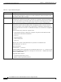
Tips
The SNR estimate for a cable modem installed at a headend should be between 35 dB and
39 dB. Although the exact value displayed will vary from cable modem to cable modem,
values collected on the same cable modem from measurement to measurement will be
consistent. Maximizing SNR optimizes cable modem reliability and service quality.
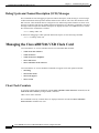
Managing Cable Modems on the HFC Network
To manage cable modems connected to the network, perform the following as appropriate:
Caution
•
Configure Sync Message Interval
•
Activate Cable Modem Authentication
•
Activate Cable Modem Upstream Address Verification
•
Configure Dynamic Contention Algorithms (Cable Insertion Interval, Range, and Data Backoffs)
•
Configure the Dynamic Map Advance Algorithm
•
Configure Per Modem Filters
•
Configure the Maximum Number of Hosts Attached to a Cable Modem
•
Configure Cable Modem Registration Timeout
•
Clear Cable Modem Reset
•
Clear Cable Modem Counters
•
Configure Traffic Shaping
•
Configure Spectrum Management (without the Cisco MC16S Cable Modem Card)
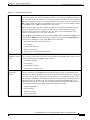
Cisco recommends using default values for most commands. Default settings are adequate
for most systems.
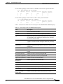
Configure Sync Message Interval
To specify the interval between successive sync message transmissions from the Cisco uBR7200 series,
use the following command in cable interface configuration mode.
Table 4-1
Instructions to Configure Sync Message Interval
Command
Purpose
CMTS01(config-if)#cable sync-interval msec
Specify the interval in milliseconds between
successive sync message transmissions from the
Cisco uBR7200 series. Valid values are from
1 to 200 msec. Default = 10 msec.
no cable sync-interval
Return the sync message interval to its default
value of 10 msec.
Cisco uBR7200 Series Universal Broadband Router Software Configuration Guide
4-2
78-5897-01
Chapter 4
Troubleshooting the System
Managing Cable Modems on the HFC Network
Verify Sync Message Interval
To verify whether or not a sync message interval is configured, enter the show running-config
command and look for the cable interface configuration information. If the sync message interval is
deactivated or reset to its default value, the no sync interval command line appears in the output.
Activate Cable Modem Authentication
The Cisco uBR7200 series can be configured to require all cable modems to return a known text string
to register with the CMTS and gain access to the network. The text string can be from 1 to 80 characters
in length. To activate cable modem authentication, use the following command from cable interface
configuration mode.
Table 4-2
Instructions to Activate Cable Modem Authentication
Command
Purpose
CMTS01(config-if)# cable shared-secret [0|7]
authorization-key
Enable cable modem authentication: 0 specifies an
unencrypted authentication key; 7 specifies an
encrypted authentication key.
CMTS01(config-if)# no cable shared-secret
Disable cable modem authentication.
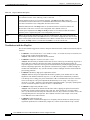
Tips
Be sure you enter the correct slot and port number in the cable interface configuration
mode. Verify that the cable modem is using BPI and that it is assigned to a QoS with
privacy active. Verify that the cable modem configuration file contains a matching key.
Verify Cable Modem Authentication
To verify whether cable modem authentication is activated or deactivated, enter the command more
system:running-config and look for the cable interface configuration information. If cable modem
authentication is deactivated, it appears in this output as no cable secret-shared.
Activate Cable Modem Upstream Address Verification
Cable modem upstream address verification ensures that only cable modems that have received DHCP
leases through the Cisco uBR7200 series can access the HFC network. The Cisco uBR7200 series
discards all packets received from or for hosts that have not received DHCP-assigned addresses.
Cisco uBR7200 Series Universal Broadband Router Software Configuration Guide
78-5897-01
4-3
Chapter 4
Troubleshooting the System
Managing Cable Modems on the HFC Network
To activate cable modem upstream address verification, use the following cable interface configuration
command.
Table 4-3
Instructions to Activate Cable Modem Upstream Address Verification
Command
Purpose
CMTS01(config-if)# cable source-verify [dhcp]
Activate cable modem upstream verification. The
dhcp option specifies that queries be sent to verify
unknown IP addresses in upstream data packets.
CMTS01(config-if)# no cable source-verify
Return to the default upstream verification state.
Verify Cable Modem Upstream Address Verification
To verify whether cable modem upstream verification is activated or deactivated, enter the command
more system:running-config and look for the no cable source-verify notation in the cable
interface configuration information.
Tips
Be sure you enter the correct slot and port number when you enter the cable interface
configuration mode.
Note
If the Cisco uBR7200 series is reloaded or the ARP table is cleared, all hosts on the
network will be forced to release and renew their IP addresses. Some systems may require
restarting if the IP protocol stack is unable to renew using a broadcast IP address.
Configure Dynamic Contention Algorithms (Cable Insertion Interval,
Range, and Data Backoffs)
The Cisco uBR7200 series universal broadband router software includes:
•
An algorithm that dynamically controls the rate of upstream contention slots —initial ranging and
bandwidth-requests.
•
An algorithm that varies backoff parameters CMs use within each of the initial ranging and
bandwidth-request upstream contention subchannels.
These algorithms control the capacity of the contention subchannel and how efficiently a given
contention subchannel capacity is utilized.
In high contention mode, the Cisco uBR7200 series MAC scheduler uses collision statistics and sustains
a high frequency of initial ranging slots until it detects a steady ranging state. The CMTS dynamically
varies the frequency of initial ranging slots using the data grant utilization on the upstream channel(s).
The CMTS trades upstream bandwidth between data grants and initial ranging slots. The CMTS
auto-detects a high collision state and switches to low insertion interval mode after a steady state is
achieved where few collisions occur.
The CMTS is careful when monitoring the ranging channel health to revert to a steady state. In steady
state mode, data grants—grant utilization—receive preference over initial ranging slots.
Cisco uBR7200 Series Universal Broadband Router Software Configuration Guide
4-4
78-5897-01
Chapter 4
Troubleshooting the System
Managing Cable Modems on the HFC Network
Although the binary exponential backoff algorithm operates in a distributed fashion at different CMs,
the CMTS provides centralized control for the backoff algorithm. To achieve this, it remotely monitors
traffic load—the backlog developing on the contention channel—and then varies the backoff start and
end specified in the MAPs for that upstream channel. This ensures colliding CMs are properly
randomized in time.
The following cable interface commands are available to configure the dynamic contention algorithms:
[no] cable insertion-interval [automatic [<Imin [Imax]>]] | [<msecs>]
[no] cable upstream <port num> range-backoff [automatic] | [<start> <end>]
[no] cable upstream <port num> data-backoff [automatic] | [<start> <end>]
Tips
System defaults are to have dynamic ranging interval enabled, dynamic ranging backoff
enabled, and fixed data backoffs for each upstream of a cable interface.
The default automatic insertion interval setting enables the Cisco automatic initial ranging period
algorithm where lower and upper default values of 50 msecs and 2 secs are used. The default automatic
range-backoff enables the dynamic backoff algorithm.
To deviate from system defaults, use one of the following commands in cable interface configuration
mode.
Table 4-4
Instructions to Modify Dynamic Contention Algorithm Defaults
Command
Purpose
CMTS01(config-if)# [no] cable insertion-interval
automatic
Disable or enable the dynamic ranging interval
algorithm. If lower and upper bounds for varying the
period are not specified, the system uses default values
of 50 msecs and 2 secs respectively.
CMTS01(config-if)# cable insertion-interval automatic min
<25-2000>
Set the lower bound on the initial ranging period for
the auto ranging algorithm.
CMTS01(config-if)# cable insertion-interval max
<500-2000>
Set the upper bound on initial ranging period for the
auto ranging algorithm.
CMTS01(config-if)# no cable insertion-interval
Reset fixed initial ranging period to default value of
500 msecs. Also invokes fixed initial ranging
algorithm.
CMTS01(config-if)# cable insertion-interval <100-2000>
Enabled fixed initial ranging period algorithm with
specified fixed period (msecs).
Configure the Dynamic Map Advance Algorithm
A CMTS administrator can enhance the upstream throughput from a cable modem connected to the
Cisco uBR7200 series. The system employs a new algorithm that auto tunes the lookahead time in
MAPs based on several input parameters for the corresponding upstream channel. The use of
dynamic/optimal lookahead time in MAPs significantly improves the per-modem upstream throughput.
Cisco uBR7200 Series Universal Broadband Router Software Configuration Guide
78-5897-01
4-5
Chapter 4
Troubleshooting the System
Managing Cable Modems on the HFC Network
Caution
Only a trained CMTS administrator should adjust these values.
To configure the dynamic map advance algorithm, use the following command in cable interface
configuration mode.
Table 4-5
Instructions to Configure the Dynamic Map Advance Algorithm
Command
Purpose
CMTS01(config-if)#cable map-advance dynamic [<n>] | static
Specify a value to enhance the upstream
throughput from a cable modem connected to the
Cisco uBR7200 series. The <n> parameter
provides the safety factor for the dynamic map
advance algorithm. This parameter is specified in
usecs and controls the amount of extra lookahead
time in MAPs to account for inaccuracies of the
measurement system and software latencies. The
default value is 1000 usecs.
You can vary this between 500 to 1500 usecs. This
parameter is a delta value added to the dynamic
map-advance that the algorithm computes. Using
larger safety factors increases the run time
lookahead in MAPs, but reduces the upstream
performance.
Use the static keyword for the map advance
command. The Cisco uBR7200 series will use a
fixed lookahead time in MAPs, regardless of the
real propagation delay of the farthest cable modem
on the network. This fixed lookahead time is
computed based on the worst case parameters such
as farthest DOCSIS propagation delay for the
CMs.
Caution
Cisco recommends if you are adjusting the dynamic map advance algorithm that you do
not reduce the safety factor below the default value of 1000 usecs in a production network
until you are confident that the reduced safety factor suffices for your deployment. The
default value is chosen to be a safe operating point for the algorithm.
Configure Per Modem Filters
You can configure the Cisco uBR7200 series to filter incoming packets from individual hosts or
cable modems based on the source Media Access Controller (MAC) or Internet Protocol (IP) address.
Definition of filters follows standard Cisco IOS configuration practices for access lists and groups.
Note
Configuring per modem or host filters is supported in Cisco IOS Release 12.0(5)T1 or
higher, as well as in Cisco IOS Release 12.0(6)SC or higher.
Cisco uBR7200 Series Universal Broadband Router Software Configuration Guide
4-6
78-5897-01
Chapter 4
Troubleshooting the System
Managing Cable Modems on the HFC Network
To configure per modem filters, use the following commands in cable interface configuration mode.
Table 4-6
Instructions to Configure Per Modem Filters
Command
Purpose
CMTS01(config-if)# cable {modem | host | device}
{<macaddr><ipaddr> | } access group <acl>
Configure access lists to be specified on a
per-interface and per-direction basis. The packets
received from cable modems and/or individual hosts
are filtered based on the cable modem or the host the
packets are received from. Use modem if the device
is a cable modem. Use host if the device is a CPE
device attached to a cable modem.
Define the filter to be applied to the device and a
given address. The macaddr specifies the cable
modem’s or CPE device’s unique MAC address.
Use the ipaddr option to specify the CM or CPE
device’s current IP address.
Use the acl option to assign the CM or CPE device
to an access list. This defines the per-CM or per-host
filter requirements implemented at the CMTS, rather
than at the CM. Access list numbers are 1 to 99 for
fast IP access lists, 100 to 199 for show extended IP
access lists.
Note
Caution
Access list numbers of 700 to
799 do not apply.
The system applies filters after the cable modem registers with the CMTS. Filter
definitions are not saved across system reboots and must be applied each time a CM
registers.
The software supports traps to alert CMTS administrators on CMs going offline or back online. A
typical registration and login procedure is shown below:
1.
The CM registers with the Cisco uBR7200 series.
2.
The Cisco uBR7200 series sends traps to management systems in use for the network.
3.
The management system sets per modem filters using SNMP or rsh.
4.
The user logs in at the server.
5.
The login server obtains required modem and CPE information from the Cisco uBR7200 series.
6.
The login server sets per-CPE filter in the Cisco uBR7200 series. The per-CPE filter overrides the
per modem filter settings.
7.
If the CM goes offline for a brief period of time, filters defined using the Cisco uBR7200 series
remain active. If a CM stays offline for more than 24 hours, filter settings are reset.
8.
If the user logs out or the login server detects that the user is not online, the login server sets default
filters for the CM or the CPE device.
Cisco uBR7200 Series Universal Broadband Router Software Configuration Guide
78-5897-01
4-7
Chapter 4
Troubleshooting the System
Managing Cable Modems on the HFC Network
Configure the Maximum Number of Hosts Attached to a Cable Modem
To specify the maximum number of hosts that can be attached to a subscriber’s cable modem, use the
following command in cable interface configuration mode.
Table 4-7
Instructions to Configure the Maximum Number of Hosts Attached to a Cable Modem
Command
Purpose
CMTS01(config-if)# cable max-hosts n
Specify the maximum number of hosts that can be
attached to a cable modem on this interface. Valid
range is from 0 to 255 hosts. Default = 0.
CMTS01(config-if)# no cable max-hosts
Reset the allowable number of hosts attached to a
cable modem to the default value of 0 hosts.
Configure Cable Modem Registration Timeout
By default, registered cable modems that have no upstream activity for three minutes are timed out and
disconnected from the Cisco uBR7200 series. This timeout interval can be decreased to 2 minutes or
increased up to 60 minutes.
To specify the registration timeout interval for cable modems connected to the Cisco uBR7200 series,
use the following command in cable interface configuration mode.
Table 4-8
Instructions to Configure Cable Modem Registration Timeout
Command
Purpose
CMTS01(config-if)# cable registration-timeout n
Specify the maximum number of minutes allowed to
elapse with no upstream activity before terminating
the connection. Valid range is from 2 to 60 minutes.
Default = 3 minutes.
Clear Cable Modem Reset
To remove a single cable modem (or all cable modems) from the station maintenance list and reset the
cable modem (or all cable modems) on the network, use one of the following commands in cable
interface configuration mode.
Cisco uBR7200 Series Universal Broadband Router Software Configuration Guide
4-8
78-5897-01
Chapter 4
Troubleshooting the System
Managing Cable Modems on the HFC Network
Table 4-9
Instructions to Clear Cable Modem Reset
Command
Purpose
CMTS01(config-if)# clear cable modem mac-addr reset
Remove the cable modem with a specific MAC address
from the station maintenance list and reset it.
CMTS01(config-if)# clear cable modem ip-addr reset
Remove the cable modem with a specific IP address
from the station maintenance list and reset it.
CMTS01(config-if)# clear cable modem all reset
Remove all cable modems from the station
maintenance list and reset them.
Verify Clear Cable Modem Reset
To verify whether or not the clear cable modem reset command has removed a cable modem from the
station maintenance list and forced it to start a reset sequence, enter the show cable modem command.
Tips
Be sure you entered the correct cable modem IP address or MAC address when you typed
the command. It might take up to 30 seconds for the cable modem to start the reset
sequence.
Note
This command is useful if an SNMP manager is not available, or if the cable modem is
unable to obtain an IP address or respond to SNMP messages.
Clear Cable Modem Counters
To clear the counters for a cable modem (or for all cable modems) in the station maintenance list, use
one of the following commands in cable interface configuration mode.
Table 4-10
Instructions to Clear Cable Modem Counters
Command
Purpose
CMTS01(config-if)# clear cable modem mac-addr counters
Clear the counters in the station maintenance list for
the cable modem with a specific MAC address.
CMTS01(config-if)# clear cable modem ip-addr counters
Clear the counters in the station maintenance list for
the cable modem with a specific IP address.
CMTS01(config-if)# clear cable modem all counters
Clear the counters in the station maintenance list for all
cable modems.
Cisco uBR7200 Series Universal Broadband Router Software Configuration Guide
78-5897-01
4-9
Chapter 4
Troubleshooting the System
Managing Cable Modems on the HFC Network
Verify Clear Cable Modem Counters
To verify whether or not the counters in the Station Maintenance List are cleared, enter the following
command. The station maintenance list counter will be 0.
Configure Traffic Shaping
Configure Downstream Rate Limiting and Shaping
To configure downstream rate limiting or shape downstream traffic, use the following command in cable
interface configuration mode.
Table 4-11
Instructions to Configure Downstream Shaping
Command
Purpose
CMTS01(config-if)#[no] cable downstream rate-limit
token-bucket [shaping] weighted-discard [expwt <n>]
Enables or disables rate limiting and traffic
shaping on the downstream of a cable interface.
Note
Using Cisco IOS Release 12.0(5)T1 or higher, the software adds downstream calendar
queuing routines and grant shaping application of the calendar queues.
Key command usage is elaborated below:
•
To enable rate limiting on the given downstream port using the token bucket policing algorithm,
issue the cable downstream rate-limit token-bucket command.
•
To enable rate limiting on the given downstream port using the token bucket policing algorithm
with traffic shaping, issue the cable downstream rate-limit token-bucket shaping command.
•
To enable rate limiting on the given downstream port using the token bucket policing algorithm
with a specific traffic shaping time granularity, issue the cable downstream rate-limit token-bucket
shaping granularity 8 command. Acceptable values are 1, 2, 4, 8, or 16 msecs.
•
To enable rate limiting on the given downstream port using the token bucket policing algorithm
with a specific maximum traffic shaping buffering delay, issue the cable downstream rate-limit
token-bucket shaping granularity 8 command. Acceptable values are 128, 256, 512, or
1028 msecs.
•
To remove rate limiting on the given downstream port, issue the cable downstream rate-limit
token-bucket command.
•
To enable rate limiting on the given downstream port using a weighted packet discard policing
algorithm and to assign a weight for the exponential moving average of loss rate value, issue the
cable downstream rate-limit weighted-discard 3 command. Acceptable values are 1 to 4.
Configure Upstream Rate Limiting and Shaping
You can rate limit and shape traffic on a DOCSIS upstream channel. This delays the scheduling of the
upstream packet, which in turn causes the packet to be buffered on the cable CPE device, instead of
being dropped. This allows the user’s TCP/IP stack to pace the application traffic appropriately and
approach throughput commensurate with the subscriber’s defined QoS levels.
Cisco uBR7200 Series Universal Broadband Router Software Configuration Guide
4-10
78-5897-01
Chapter 4
Troubleshooting the System
Managing Cable Modems on the HFC Network
To configure this, use the following command in cable interface configuration mode.
Table 4-12
Instructions to Configure Upstream Shaping
Command
Purpose
CMTS01(config-if)#[no] cable upstream <n1> rate-limit
[token-bucket]
Enables or disables DOCSIS rate limiting or
shaping on an upstream channel. <n1> depends on
the number of upstream channels on the specific
cable modem card.
Using Cisco IOS Release 12.0(5)T1 or higher, the software supports:
•
Generic calendar queuing routines
•
New token bucket policing function
•
Grant shaping application of the calendar queues
•
Upstream rate shaping option to the token-bucket keyword
•
A default state change from 1 second burst policing to token-bucket with shaping
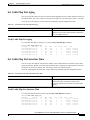
Tips
Upstream grant shaping is per CM (SID). Shaping can be enabled or disabled for the
token-bucket algorithm.
Note
Before the introduction of this feature, the CMTS would drop bandwidth requests from a
CM it detected as exceeding its configured peak upstream rate. Such request dropping
affects the throughput performance of IP-based protocols such as FTP, TCP, and SMTP.
With this feature, the CMTS can shape (buffer) the grants for a CM that is exceeding its
upstream rate, rather than dropping the bandwidth requests.
CMTS01# show interface c3/0 sid 1 counters
Sid
Inpackets Inoctets
Outpackets Outoctets
1
67859
99158800
67570
98734862
Ratelimit
BWReqDrop
2579
Ratelimit
DSPktDrop
0
Configure Spectrum Management (without the Cisco MC16S Cable
Modem Card)
Blind Strategies and Time Scheduled Combined
The Cisco uBR7200 series software supports combined blind and time scheduled spectrum
management using Cisco IOS Release 12.0(5)T1 images or higher:
•
Using blind spectrum management, the number of lost station management messages exceeding a
configured threshold (default = 10) initiates an upstream channel frequency reassignment. The
Cisco uBR7200 series moves all cable modems on the upstream port by sending UCD messages
that contain the next frequency and input power level defined in the spectrum management group.
The frequency change occurs rapidly without data loss and minimal latency.
Cisco uBR7200 Series Universal Broadband Router Software Configuration Guide
78-5897-01
4-11
Chapter 4
Troubleshooting the System
Managing Cable Modems on the HFC Network
•
Using time scheduled spectrum management, the upstream channel frequency reassignment
process is initiated at a configured time of day or week.
With combined blind and time scheduled strategies, blind hop tables are given time-variant
configurability. The frequency or subband list can change with time. Blind frequency hop is performed
within the spectrum specified to be currently available. An example follows:
uBR(config)#
uBR(config)#
uBR(config)#
uBR(config)#
uBR(config)#
cable
cable
cable
cable
cable
spectrum-group
spectrum-group
spectrum-group
spectrum-group
spectrum-group
2
2
2
4
4
time
time
time
time
time
Mon
Tue
Tue
Fri
Sat
09:00:00
09:05:00
09:00:00
09:00:00
09:00:00
frequency 10000000
delete frequency 10000000
frequency 5000000
band 15000000 25000000
delete band 15000000 25000000
Guided Frequency Hop
Using guided frequency hop, the upstream channel frequency is reassigned if a threshold number or
percentage of cable modems suddenly go offline. You can adjust the thresholds and assign explicit
frequencies or frequency subbands and associated input power levels in the unified spectrum group
table. The Cisco uBR7200 series locates the defined channel or a suitable channel and moves all cable
modems on the upstream port.
The example below shows the Cisco uBR7200 series’ ability to force the CTMS to change the upstream
to another frequency before the CMTS sends a message to increase output power levels. You can
configure the frequency hop table so that the next entry has the same frequency, but a different power
level:
uBR(config)#
uBR(config)#
uBR(config)#
uBR(config)#
uBR(config)#
uBR(config)#
cable
cable
cable
cable
cable
cable
spectrum-group
spectrum-group
spectrum-group
spectrum-group
spectrum-group
spectrum-group
2
2
2
2
2
2
frequency
frequency
frequency
frequency
frequency
frequency
20000000
20000000
20000000
22000000
22000000
22000000
2
-2
2
3
The order of the configuration commands defines the order which frequency or power level is changed.
There is always a single allocation set per-spectrum group, listing the currently available bands. In the
case of a shared spectrum group, there is also a single free set and “in-use” set since there is a single
RF domain. Otherwise, there are free and in-use sets for each upstream port since each upstream port
has its own RF domain.
Cisco uBR7200 Series Universal Broadband Router Software Configuration Guide
4-12
78-5897-01
Chapter 4
Troubleshooting the System
Managing Cable Modems on the HFC Network
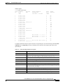
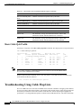
Sample output:
noisy1#show cable spec
Group Frequency
Upstream
No.
Band
Port
(Mhz)
1
1
1
1
1
2
2
3
3
3
3
3
3
4
4
5
5
5
5
5
5
5
6
6
6
10.000- 0.000
11.000- 0.000
12.000- 0.000
13.000- 0.000
14.000- 0.000
10.000-15.000
10.208 [0.40]
20.000- 0.000
21.000- 0.000
22.000- 0.000
23.000- 0.000
24.000- 0.000
0.400 [0.80]
20.000-25.000
20.800 [1.60]
10.000- 0.000
11.000- 0.000
12.000- 0.000
13.000- 0.000
14.000- 0.000
13.000- 0.000
1.600 [3.20]
10.000-13.000
13.000-15.000
10.800 [1.60]
Weekly Scheduled
Availability
From Time:
To Time:
Cable3/0 U1
Cable3/0 U2
Cable3/0 U3
Mon 17:06:00
Mon 17:08:00
Mon 17:10:00
--- --:--:---- --:--:---- --:--:--
Mon 17:11:00
Mon 17:12:00
Cable3/0 U4
Cable3/0 U5
Power
Level
(dBmV)
Shared
Spectrum
1
1
1
1
1
2
2
3
3
3
3
3
3
4
4
5
5
5
5
5
5
5
6
6
0
No
No
No
No
No
No
Yes
Yes
Yes
Yes
Yes
Yes
No
No
No
No
No
No
No
No
To display information about a specific interface or upstream port, enter the following command:show
cable hop cable-if [upstream portnum]. Information lines describe the frequency hop status of an
upstream port.
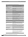
Table 4-13
Show Cable Hop Parameter Descriptions
Field
Description
Upstream Port
The upstream port for this information line
Port Status
Show “down” if frequency is unassigned, “admindown” if the port is
shutdown, or the center frequency of the channel if the port is up
Poll Rate
The rate station maintenance polls are generated (msec)
Missed Poll Count
The number of missing polls
Min Poll Sample
The number of polls in the sample
Missed Poll Pcnt
The ratio of missing polls to the number of polls displayed as a percentage
Hop Thres Pcnt
The level that the missed poll percentage must exceed to trigger a frequency
hop expressed as a percentage
Hop Period
The maximum rate which frequency hopping will occur (seconds)
Corr FEC Errors
The number of correctable FEC errors on this upstream port
Uncorr FEC Errors
The number of uncorrectable FEC errors on this upstream port
Cisco uBR7200 Series Universal Broadband Router Software Configuration Guide
78-5897-01
4-13
Chapter 4
Troubleshooting the System
Managing Cable Modems on the HFC Network
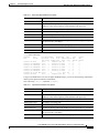
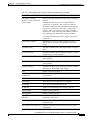
Sample output:
noisy1#show cable hop
Upstream
Port
Port
Status
Cable3/0/U0
Cable3/0/U1
Cable3/0/U2
Cable3/0/U3
Cable3/0/U4
Cable3/0/U5
Cable4/0/U0
Cable6/0/U0
Poll
Rate
(ms)
down
1000
admindown 1000
admindown 1000
admindown 1000
admindown 1000
admindown 1000
10.800 Mhz 1000
down
1000
Missed
Poll
Count
* * *
* * *
* * *
* * *
* * *
* * *
0
* * *
Min
Missed Hop
Hop
Corr
Poll
Poll
Thres Period FEC
Sample Pcnt
Pcnt (sec)
Errors
frequency not set
* * * 0
interface is down
* * * 0
interface is down
* * * 0
interface is down
* * * 0
interface is down
* * * 0
interface is down
* * * 0
0
----- 100% 300
0
frequency not set
* * * 0
Uncorr
FEC
Errors
0
0
0
0
0
0
0
0
Spectrum Management Debug and Test Commands
To enable display of frequency hopping debugging messages, enter:
debug cable freqhop
To enable display of spectrum management debugging messages, enter:
debug cable specmgmt
This command also enables display of channel width list and offer list for the show cable
spectrum-group command.
To force a frequency hop decision on the port or ports, enter:
test cable hop cable-if [upstream portnum]
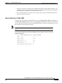
Show Cable Hop Command
Using Cisco IOS Release 12.0(5)T1 or higher headend images, you can use the following command to
obtain specific upstream interface information:
show cable hop cable-if [upstream <portnum>]
Cisco uBR7200 Series Universal Broadband Router Software Configuration Guide
4-14
78-5897-01
Chapter 4
Troubleshooting the System
Managing Cable Modems on the HFC Network
Table 4-14
Show Cable Hop Parameter Descriptions
Field
Description
Upstream Port
The upstream port for this information line
Port Status
Show “down” if frequency is unassigned, “admindown” if the port is
shutdown, or the center frequency of the channel if the port is up
Poll Rate
The rate station maintenance polls are generated (msec)
Missed Poll Count
The number of missing polls
Min Poll Sample
The number of polls in the sample
Missed Poll Pcnt
The ratio of missing polls to the number of polls expressed as a percentage
Hop Thres Pcnt
The level that the missed poll percentage must exceed to trigger a frequency
hop expressed as a percentage
Hop Period
The maximum rate which frequency hopping will occur (seconds)
Corr FEC Errors
The number of correctable FEC errors on this upstream port
Uncorr FEC Errors
The number of uncorrectable FEC errors on this upstream port
noisy1#show cable hop
Upstream
Port
Port
Status
Cable3/0/U0
Cable3/0/U1
Cable3/0/U2
Cable3/0/U3
Cable3/0/U4
Cable3/0/U5
Cable4/0/U0
Cable6/0/U0
Poll
Rate
(ms)
down
1000
admindown 1000
admindown 1000
admindown 1000
admindown 1000
admindown 1000
10.800 Mhz 1000
down
1000
Missed
Poll
Count
* * *
* * *
* * *
* * *
* * *
* * *
0
* * *
Min
Missed Hop
Hop
Corr
Poll
Poll
Thres Period FEC
Sample Pcnt
Pcnt (sec)
Errors
frequency not set
* * * 0
interface is down
* * * 0
interface is down
* * * 0
interface is down
* * * 0
interface is down
* * * 0
interface is down
* * * 0
0
----- 100% 300
0
frequency not set
* * * 0
Uncorr
FEC
Errors
0
0
0
0
0
0
0
0
Using Cisco IOS Release 12.0(5)T1 or higher headend images, you can use the following command to
obtain specific upstream interface information:
show cable hop cable-if [upstream <portnum>]
Table 4-15
Upstream Port Parameter Descriptions
Field
Description
Upstream Port
The upstream port for this information line
Port Status
Show “down” if frequency is unassigned, “admindown” if the port is
shutdown, or the center frequency of the channel if the port is up
Poll Rate
The rate station maintenance polls are generated (msec)
Missed Poll Count
The number of missing polls
Min Poll Sample
The number of polls in the sample
Missed Poll Pcnt
The ratio of missing polls to the number of polls expressed as a percentage
Hop Thres Pcnt
The level that the missed poll percentage must exceed to trigger a frequency
hop expressed as a percentage
Hop Period
The maximum rate at which frequency hopping will occur (seconds)
Cisco uBR7200 Series Universal Broadband Router Software Configuration Guide
78-5897-01
4-15
Chapter 4
Troubleshooting the System
Polling Cable Modems
Table 4-15
Upstream Port Parameter Descriptions (continued)
Field
Description
Corr FEC Errors
The number of correctable FEC errors on this upstream port
Uncorr FEC Errors
The number of uncorrectable FEC errors on this upstream port
Sample output:
noisy1#show cable hop
Upstream
Port
Port
Status
Cable3/0/U0
Cable3/0/U1
Cable3/0/U2
Cable3/0/U3
Cable3/0/U4
Cable3/0/U5
Cable4/0/U0
Cable6/0/U0
Poll
Rate
(ms)
down
1000
admindown 1000
admindown 1000
admindown 1000
admindown 1000
admindown 1000
10.800 Mhz 1000
down
1000
Missed
Poll
Count
* * *
* * *
* * *
* * *
* * *
* * *
0
* * *
Min
Missed Hop
Hop
Corr
Poll
Poll
Thres Period FEC
Sample Pcnt
Pcnt (sec)
Errors
frequency not set
* * * 0
interface is down
* * * 0
interface is down
* * * 0
interface is down
* * * 0
interface is down
* * * 0
interface is down
* * * 0
0
----- 100% 300
0
frequency not set
* * * 0
Uncorr
FEC
Errors
0
0
0
0
0
0
0
0
Debug and Test Commands
To enable display of frequency hopping debugging messages, enter:
debug cable freqhop
To enable display of spectrum management debugging messages, enter:
debug cable specmgmt
To force a frequency hop decision on the port or ports, enter:
test cable hop cable-if I portnum
Polling Cable Modems
Cisco IOS Release 12.0(7)XR2, Cisco IOS Release 12.1(1a)T1 or higher CMTS images, contain
modem status enhancements. You can obtain operating statistics and determine the state of cable
modems on the network.
The Cisco uBR7200 series supports polling of cable modems to obtain parameter and status information
on an ongoing basis. Two new Cisco IOS commands are added to support the feature:
•
The cable modem remote command configures the router for the polling interval; the no version
of this command disables the status polling.
•
The show cable modem remote-query command displays the collected information: downstream
receive power level, downstream signal to noise ratio, upstream power level, micro reflection in dB.
The Cisco uBR7200 series polls cable modems on the network and caches the state information on the
CMTS, allowing administrators to use SNMP to manage the system.
This section describes how you can enable this. See the following configuration tasks:
•
Enable SNMP (required)
•
Configure Remote Modem Monitoring (required)
Cisco uBR7200 Series Universal Broadband Router Software Configuration Guide
4-16
78-5897-01
Chapter 4
Troubleshooting the System
Polling Cable Modems
Enable SNMP
Command
Purpose
Router(config)# snmp-server manager
Opens the SNMP manager
Router(config)# snmp-server community [Community String]
[Permissions]
Defines user permissions
Configure Remote Modem Monitoring
Command
Purpose
Router(config)# cable modem remote-query [polling interval]
[Community string]
Specifies how often SNMP polls the modem and
allows you to configure access
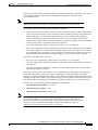
Verifying Remote Query Information
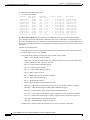
To display information from a queried modem, enter the show cable modem remote-query command.
R7732-01-uBR7246#sh cable modem remote-query
IP address
MAC address
S/N
US
Ratio Power
5.108.1.2
0010.4bd7.ccf2
0.0
0.0
5.109.1.2
0000.0000.0022
0.0
0.0
5.110.1.2
0000.0000.0023
0.0
0.0
5.108.1.5
0000.0000.0026
0.0
0.0
5.108.1.4
0000.0000.0024
0.0
0.0
5.108.1.3
0000.0000.0025
0.0
0.0
Tips
DS
Power
0.0
0.0
0.0
0.0
0.0
0.0
Tx Time
Offset
0
0
0
0
0
0
Micro (dB) Modem
Reflection State
0 offline
0 offline
0 offline
0 offline
0 offline
0 offline
To display debugging information, enter the debug cable remote-query command.
See the following for an example debug message of a successful poll of a cable modem:
router# debug cable remote-query
remote-query debugging is on
.
For IP address 209.165.200.223
Nov 10 15:56:50.241: docsIfSignalQualityEntry.5.4 = 380
Nov 10 15:56:50.241: docsIfMibObjects.2.2.1.3.2 = 360
Nov 10 15:56:50.245: docsIfDownstreamChannelEntry.6.4 = -30
Nov 10 15:56:50.245: docsIfUpstreamChannelEntry.6.3 = 12422
Nov 10 15:56:50.249: docsIfSignalQualityEntry.6.4 = 0
Nov 10 15:56:50.477:
See the following for an example debug message when the waiting queue at the CMTS is empty:
SNMP proxy exec got event, but queue is empty
See the following for an example debug message when you try to modify the polling interval or
community string while polling in is progress:
Community string if modified will not be reflected
Note
The polling interval will be changed. To change the community string, you must
unconfigure the snmp-server community command and reconfigure it with the new
community string.
Cisco uBR7200 Series Universal Broadband Router Software Configuration Guide
78-5897-01
4-17
Chapter 4
Troubleshooting the System
Understanding Show Command Responses
Monitoring and Maintaining Remote Querying
Use the following show commands to gather status information about the specified modems.
Command
Purpose
Router# show cable flap-list
Displays statistics on the quality of the modem
connection.
Router# show cable modem
Displays statistics on modem states.
Router# show cable modem remote-query
Displays statistics gathered by SNMP agents on
modem states.
Router# show interface cable
Displays statistics on the quality of the cable
interface.
Router# show interface cable sid
Displays statistics on the service IDs of the specified
modems.
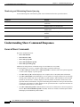
Understanding Show Command Responses
General Show Commands
Key show commands include:
•
show cable modem
•
show interface cable
•
show cable qos profile
•
show cable modulation profile
•
show cable spectrum-group
Additional or changed show commands using Cisco IOS Release 12.0(7)XR2,
Cisco IOS Release 12.1(1a)T1, or higher CMTS images include the following:
•
The show cable qos command shows cable qos-profile n command, where the optional argument
n can be used to display a specific profile.
•
The show int cx/y sid command displays more complete Service ID (SID) status information.
•
The show cable modem command displays a list of options for a single modem to be specified by
entering either the RF CPE device's IP address or MAC address: SNR information for each cable
modem on each interface, summary display of the total number of modems connected for each
upstream channel, total number of registered and unregistered modems for the specified interface
or upstream, total number of offline modems for the specified interface or upstream and status for
each offline modem before it went offline.
•
The show cable burst-profile command has been removed. Its functions have been incorporated
into the show cable modulation-profile command, which now includes an added option number
that displays the modulation profile number.
Cisco uBR7200 Series Universal Broadband Router Software Configuration Guide
4-18
78-5897-01
Chapter 4
Troubleshooting the System
Understanding Show Command Responses
•
The show cable flap-list and show cable modem commands now indicate when the Cisco
uBR7200 series router has detected an unstable return path for a particular modem and has
compensated with a power adjustment. An asterisk appears in the power adjustment field for a
modem when a power adjustment has been made; an exclamation point appears when the modem
has reached its maximum power transmit level and cannot increase its power level any further.
•
The show controller upstream command is enhanced to display the following information on
cable interfaces:
– Upstream channel utilization in minislots
– Contention slots
– Initial ranging slots
– Minislots lost due to the MAP interrupt being too late.
You can also limit your search for modem status to specific cable interfaces.
Show Cable Modem
Using Cisco IOS Release 12.0(7)XR2, Cisco IOS Release 12.1(1a)T1 or higher, the
show cable modem command includes all DOCSIS states, as well as other useful troubleshooting
information such as last received upstream RF power level and maximum number of provisioned
customer premises equipment.
Note
DOCSIS cable modems are required to pass through successive states during registration
and provisioning. Using this information, you can isolate why a cable modem is offline or
unavailable.
Specific added information includes the downstream receive power ratio, downstream SNR, upstream
and downstream power levels, transmit timing offset, and micro reflections in decibels.
For each upstream channel, you can obtain the following information:
•
The total number of modems
•
The number of active modems
•
The number of registered modems
•
The number of unregistered modems
•
The number of offline modems.
•
The time the modem went offline
•
The status before the modem went offline
•
The receive power before the modem went offline.
Cisco uBR7200 Series Universal Broadband Router Software Configuration Guide
78-5897-01
4-19
Chapter 4
Troubleshooting the System
Understanding Show Command Responses
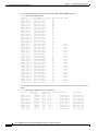
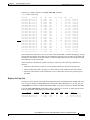
See the sample command output below:
router# show cable modem
Interface
Prim Online
Sid State
Cable3/0/U0 1
online
Cable3/0/U0 2
online
Cable3/0/U0 3
online
Cable3/0/U0 4
online
Cable3/0/U0 5
online
Cable3/0/U0 6
online
Cable3/0/U0 7
online
Cable3/0/U0 8
online
Cable3/0/U0 9
online
Cable3/0/U0 10
online
Cable3/0/U0 11
online
Timing Rec
Offset Power
2257
0.00
2262 *-0.50
2260
0.25
2256
*0.75
2265
*0.50
2256
0.00
4138 !-1.00
4142 !-3.25
4141 !-3.00
4142 !-2.75
4142 !-3.25
QoS CPE IP address
MAC address
3
3
3
3
3
3
3
3
3
3
3
0090.8330.0217
0090.8330.020f
0090.8330.0211
0090.8330.0216
0090.8330.0214
0090.8330.0215
0050.7366.124d
0050.7366.1245
0050.7366.17e3
0050.7366.17ab
0050.7366.17ef
0
0
0
0
0
0
1
1
1
0
1
10.30.128.142
10.30.128.145
10.30.128.146
10.30.128.143
10.30.128.140
10.30.128.141
10.30.128.182
10.30.128.164
10.30.128.185
10.30.128.181
10.30.128.169
The show cable modem indicates when the Cisco uBR7200 series router has detected an unstable
return path for a particular CM and has compensated with a power adjustment. An asterisk appears in
the power adjustment field for a CM when a power adjustment has been made; an exclamation point
appears when the CM has reached its maximum power transmit level and cannot increase its power level
any further.
Columns are described below:
•
The prim Sid column reveals the primary (lifeline) service identifier assigned to the cable modem.
•
The SID column is the service identifier.
•
The Online State column reveals the state of the modem; values include:
– offline—Cable modem considered offline
– offline time—the time the cable modem went offline; the format is the same as other show cable
modem commands (month, day, time, and year)
– init (r1)—Cable modem sent initial ranging
– init (r2)—Cable modem is ranging
– init (rc)—Cable modem ranging complete
– init (d)—Dhcp request received
– init (i)—Dhcp reply received; IP address assigned
– init (o)—Option file transfer started
– init (t)—TOD exchange started
– online—Cable modem registered, enabled for data
– online(d)—Cable modem registered, but network access for the cable modem is disabled
– online(pk)—Cable modem registered, BPI enabled and KEK assigned
– online(pt)—Cable modem registered, BPI enabled and TEK assigned
– reject (m)—Cable modem did attempt to register; registration was refused due to bad MIC
– reject (c)—Cable modem did attempt to register; registration was refused due to bad COS
– reject (pk)—KEK modem key assignment rejected
– reject (pt)—TEK modem key assignment rejected
•
The Rec Power column contains the nominal receive power in decibels for this SID
Cisco uBR7200 Series Universal Broadband Router Software Configuration Guide
4-20
78-5897-01
Chapter 4
Troubleshooting the System
Understanding Show Command Responses
Note
* means the noise power adjustment method is active for this modem; ! means
the modem has reached its maximum transmit power
•
The QoS column contains the service class assigned to the modem
•
The CPE column identifies the number of devices behind the modem
•
The Max CPE column identifies the maximum number of devices configured for the modem
•
The IP address reveals the modem’s IP address
•
The MAC address reveals the modem’s MAC address
•
The Concatenation column reveals if concatenation is enabled (yes) or disabled (no)
•
The Rx SNR column reveals the SNR ratio level in dBmV as perceived by the cable modem
Note
This parameter is only meaningful for cable modems. A CMTS will return a
zero.
•
The S/N Ratio column provides values for remote-queried modems.
•
The US Power column reveals the transmit power level for the upstream channel in dBmV.
•
The DS Power column reveals the received power level at the downstream modem in dBmV.
Note
If the power level measurement is not supported, set this parameter to zero.
Also, if the interface is down, this value will be the CMTS-configured value,
the most current CM value, or zero.
•
The Tx Timing Offset shows the current round trip time at the CM. The value is used to synchronize
upstream transmission to the CMTS and is measured in units of 6.25 microseconds.
•
The Micro (dB) Reflection column is the total microreflections including in-channel response as
perceived on this interface, measured in Dbc below the signal level.
Note
The value is not assumed to return an absolutely accurate value, but gives a
rough indication of microreflections received on this interface.
•
The Offline Time column reveals when a modem went offline.
•
The Previous State column reveals the modem’s status prior to going offline. See the modem
ranging states given earlier.
•
The Rx Power column reveals the last receive power measurement for a modem that is offline
before it went offline.
•
SM Exhaust Count reveals the number of times the CMTS declared that modem offline. The modem
can be marked offline for various reasons. Refer to Show Cable Modem Maintenance, page 4-23.
Cisco uBR7200 Series Universal Broadband Router Software Configuration Guide
78-5897-01
4-21
Chapter 4
Troubleshooting the System
Understanding Show Command Responses
See the following sample for detailed output of the show cable modem command:
router#show
Interface
Cable3/0/U0
Cable3/0/U0
Cable3/0/U0
Cable3/0/U0
Cable3/0/U0
Cable3/0/U0
Cable3/0/U0
Cable3/0/U0
Cable3/0/U0
Cable3/0/U0
Cable3/0/U0
Cable3/0/U0
Cable3/0/U0
Cable3/0/U0
Cable3/0/U0
Cable4/0/U0
Cable4/0/U1
Cable4/0/U1
Cable4/0/U0
Cable4/0/U1
Cable4/0/U1
Cable4/0/U0
Cable4/0/U0
Cable4/0/U1
Cable4/0/U1
Cable4/0/U1
Cable4/0/U0
Cable4/0/U1
Cable4/0/U0
Cable4/0/U0
Cable4/0/U1
Cable4/0/U0
Cable4/0/U0
Cable4/0/U0
Cable4/0/U0
Cable4/0/U1
Cable4/0/U0
Cable4/0/U0
Cable4/0/U0
cable modem detail
SID MAC address
1
0090.8330.0215
2
0090.8330.0213
3
0090.8330.0214
4
0090.8330.0217
5
0090.8330.020f
6
0050.7366.17e3
7
0090.8330.0211
8
0050.7366.17af
9
0090.8330.0216
10
0050.7366.1801
11
0050.7366.124d
12
0050.7366.1241
13
0050.7366.17db
14
0050.7366.1239
15
0050.7366.17ab
1
0050.7366.1db1
2
0050.7318.e97f
3
0050.7318.e965
4
0050.7318.e931
5
0050.7318.e92d
6
0050.7318.e97b
7
0050.7366.1d8d
8
0050.7318.e953
9
0050.7366.1d9d
10
0050.7318.e96b
11
0050.7366.1d95
12
0050.7318.e93f
13
0050.7318.e96d
14
0050.7318.e941
15
0050.7366.1dcd
16
0050.7318.e939
17
0050.7366.1d8f
18
0050.7302.3da3
19
0050.7318.e93b
20
0050.7318.e901
21
0050.7366.1dbb
22
0050.7318.e957
23
0050.7318.e985
24
0050.7366.1dbd
Max CPE
3
3
3
3
3
3
3
3
3
3
3
3
3
3
3
3
3
3
3
3
3
3
3
3
3
3
3
3
3
3
3
3
3
3
3
3
3
3
3
Concatenation Rx SNR
yes
yes
yes
yes
yes
no
yes
no
yes
no
no
no
no
no
no
no
26.50
no
23.87
no
23.85
no
26.72
no
23.31
no
23.85
no
26.88
no
26.54
no
23.72
no
23.79
no
23.82
no
26.26
no
23.51
no
26.69
no
26.94
no
23.98
no
27.13
no
26.58
no
26.49
no
26.68
no
23.45
no
26.35
no
26.40
no
26.69
See the following sample output of modems connected on upstream channel 0 for cable interface slot 3,
port 0:
router#show cable modem cable 3/0 upstream 0
Interface
Prim Online
Timing Rec
QoS
Sid State
Offset Power
Cable3/0/U0 1
offline
2264
-0.50 2
Cable3/0/U0 2
offline
4137 !-3.50 2
Cable3/0/U0 3
init(d)
4136 !-2.50 2
Cable3/0/U0 4
init(d)
4138 !-4.75 2
Cable3/0/U0 5
init(d)
4137 !-2.25 2
Cable3/0/U0 6
init(o)
2251
-0.25 2
Cable3/0/U0 7
offline
2264
0.75 2
Cable3/0/U0 8
offline
2266
-0.50 2
Cable3/0/U0 9
init(rc)
4662
1.00 2
CPE IP address
MAC address
0
0
0
0
0
0
0
0
0
0090.8330.0214
0050.7366.17d3
0050.7366.17ab
0050.7366.1803
0050.7366.1801
0090.8330.0213
0090.8330.020f
0090.8330.0211
00d0.bad3.c459
209.165.200.2
209.165.200.9
209.165.200.0
209.165.200.0
209.165.200.0
209.165.200.3
209.165.200.4
209.165.200.5
209.165.200.0
Cisco uBR7200 Series Universal Broadband Router Software Configuration Guide
4-22
78-5897-01
Chapter 4
Troubleshooting the System
Understanding Show Command Responses
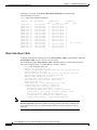
See the following sample output of unregistered modems connected on upstream channel 0 for cable
interface 3, port 0:
router#show cable modem cable 3/0 upstream 0 unregistered
Interface
Prim Online
Timing Rec
QoS CPE IP address
Sid State
Offset Power
Cable3/0/U0 1
offline
2264
-0.50 2
0
209.165.200.2
Cable3/0/U0 2
offline
4137 !-3.50 2
0
209.165.200.9
Cable3/0/U0 3
init(d)
4136 !-2.75 2
0
209.165.200.0
Cable3/0/U0 4
init(d)
4137 !-3.25 2
0
209.165.200.0
Cable3/0/U0 5
init(d)
4141 !-2.75 2
0
209.165.200.0
Cable3/0/U0 6
offline
2251
-0.25 2
0
209.165.200.3
Cable3/0/U0 7
offline
2254
-1.00 2
0
209.165.200.4
Cable3/0/U0 8
offline
2248
0.00 2
0
209.165.200.5
Cable3/0/U0 9
init(rc)
4665
-0.50 2
0
209.165.200.0
MAC address
0090.8330.0214
0050.7366.17d3
0050.7366.17ab
0050.7366.1803
0050.7366.1801
0090.8330.0213
0090.8330.020f
0090.8330.0211
00d0.bad3.c459
See the following sample output of offline modems connected on upstream channel 0 for cable
interface 3, port 0:
router#show cable modem cable 3/0 upstream 0 offline
Interface
MAC address
Prim Previous Offline
Sid State
Time
Cable3/0/U0
Cable3/0/U0
Cable3/0/U0
Cable3/0/U0
0050.7366.17d3
0090.8330.0213
0090.8330.020f
0090.8330.0211
2
6
7
8
init(o)
init(o)
init(o)
init(o)
Jan
Jan
Jan
Jan
16
16
16
16
Rx
Power
20:30:26 !-3.50
20:30:55 -0.25
20:31:07 -1.00
20:31:23
0.00
Rx
SNR
-----------------
SM
Exhaust
Count
1
181
181
181
Show Cable Modem Maintenance
When a cable modem is detected to be offline by the CMTS—no reply after 16 retries of station
maintenance requests—the cable modem is marked offline. Besides marking the cable modem and SID
state offline, the SID is removed immediately from the CMTS ranging list and an aging timer is started
to cleanup the SID completely if the cable modem does not attempt to come online within the next
24 hours.
Output fields are described below:
•
The "SM Exhausted Count" value refers to the number of times a cable modem was dropped
because it did not reply to station maintenance requests. A CM is removed from the station
maintenance list after 16 times of periodic ranging opportunity without seeing the RNG_REQ from
the modem.
•
The "SM Aborted Count" value refers to the number of times the CM was dropped because its
operational parameters were unacceptable. This includes such reasons as the power level is outside
the acceptable range, or the timing offset keeps changing. The respective times in the command
output indicate when this happened.
Cisco uBR7200 Series Universal Broadband Router Software Configuration Guide
78-5897-01
4-23
Chapter 4
Troubleshooting the System
Understanding Show Command Responses
Following is a response to the show cable modem maintenance command using
Cisco IOS Release 12.0(5)T1:
uBR7200#show cable modem maintenance
Interface
SID
MAC Address
Cable4/0/U1
Cable4/0/U0
Cable4/0/U2
Cable4/0/U0
Cable4/0/U0
Cable4/0/U0
Cable4/0/U2
Cable4/0/U1
Cable4/0/U2
Cable4/0/U1
Cable4/0/U1
Cable4/0/U1
Cable4/0/U1
Cable4/0/U2
Cable4/0/U1
1
2
11
13
16
20
24
27
28
30
31
32
33
35
36
0010.7b6b.5e27
0010.7b6b.5e15
0050.731c.b025
0050.731c.b021
0050.731c.b009
0050.731c.bfed
0050.731c.b023
0050.731c.bfeb
0050.731c.bfdf
0050.7366.1a71
0050.7366.1bab
0050.731c.bfe7
0050.731c.bfd3
0050.731c.b041
0050.7366.1ab9
SM Exhausted
SM Aborted
Count
Time
Count
Time
4
Apr 29 19:33:19
0
8
Apr 29 19:34:55
0
1
Apr 29 16:43:39
0
1
Apr 29 15:58:43
0
1
Apr 29 15:58:28
0
1
Apr 28 14:36:22
0
1
Apr 27 10:30:36
0
1
Apr 28 14:54:53
0
1
Apr 28 14:50:55
0
2
Apr 29 17:49:00
0
3
Apr 29 16:21:47
0
0
2
Jan 1 09:00:00
4
Apr 29 15:09:28
0
1
Apr 29 16:17:41
0
2
Apr 29 16:53:26
0
Show Interface Cable
To display cable interface information, use the show interface cable privileged EXEC command:
show interface cable slot/port [downstream | upstream].
See the following sample show interface cable command output for a cable modem located in
slot 6/port 0 using the earlier Cisco IOS Release 12.1(5)T1 software:
router# show interface cable 6/0
Cable6/0 is up, line protocol is up
Hardware is BCM3210 FPGA, address is 00e0.1e5f.7a60 (bia 00e0.1e5f.7a60)
Internet address is 1.1.1.3/24
MTU 1500 bytes, BW 27000 Kbit, DLY 1000 usec, rely 255/255, load 1/255
Encapsulation, loopback not set, keepalive not set
ARP type: ARPA, ARP Timeout 04:00:00
Last input 4d07h, output 00:00:00, output hang never
Last clearing of “show interface” counters never
Queueing strategy: fifo
Output queue 0/40, 0 drops; input queue 0/75, 0 drops
5 minute input rate 0 bits/sec, 0 packets/sec
5 minute output rate 0 bits/sec, 0 packets/sec
10908 packets input, 855000 bytes, 0 no buffer
Received 3699 broadcasts, 0 runts, 0 giants, 0 throttles
3 input errors, 3 CRC, 0 frame, 0 overrun, 0 ignored, 0 abort
5412 packets output, 646488 bytes, 0 underruns
0 output errors, 0 collisions, 13082 interface resets
0 output buffer failures, 0 output buffers swapped out
Note
For more recent images such as Cisco IOS Release 12.1(1a)T1 or higher, the show
interface upstream command is enhanced to display details on the MAC scheduler state
for an upstream port. Refer to “Enhanced Show Interface Upstream Output” section on
page 4-30.
Cisco uBR7200 Series Universal Broadband Router Software Configuration Guide
4-24
78-5897-01
Chapter 4
Troubleshooting the System
Understanding Show Command Responses
Table 4-16
Show Interface Cable Command Field Descriptions
Field
Description
Cable slot/port is
up/...administratively down
Indicates whether the interface hardware is currently
active or taken down by the administrator
line protocol is
up/...administratively down
Indicates whether the software processes that handle the
line protocol believe the interface is usable or if it has been
taken down by the administrator
hardware
Hardware type and address
Internet address
Internet address followed by subnet mask
MTU
Maximum Transmission Unit (MTU) of the interface
BW
Bandwidth of the interface in kilobits per second
DLY
Delay of the interface in microseconds
rely
Reliability of the interface as a fraction of 255, calculated
as an exponential average over 5 minutes. (For example,
255/255 is 100% reliability)
load
Load on the interface as a fraction of 255, calculated as an
exponential average over 5 minutes. (For example,
255/255 is complete saturation.)
Encapsulation
Encapsulation method assigned to this interface.
ARP type
Type of Address Resolution Protocol (ARP) and timeout
value assigned
Last input
Number of hours, minutes, and seconds since the last
packet was successfully received by an interface
output
Number of hours, minutes, and seconds since the last
packet was successfully transmitted by an interface
Last clearing of “show
interface” counters
Time when the counters that measure cumulative statistics,
such as number of bytes transmitted and received, were
last reset to zero
Queueing strategy
Displays the type of queueing configured for this interface.
In the example output, the type of queueing configured is
First In First Out (FIFO)
Output queue
Number of packets in the output queue. The format of this
number is A/B where A indicates the number of packets in
the queue, and B indicates the maximum number of
packets allowed in the queue
drops
Indicates the number of packets dropped due to a full
queue
input queue/drops
Number of packets in the input queue. The format of this
number is A/B where A indicates the number of packets in
the queue, and B indicates the maximum number of
packets allowed in the queue.
Cisco uBR7200 Series Universal Broadband Router Software Configuration Guide
78-5897-01
4-25
Chapter 4
Troubleshooting the System
Understanding Show Command Responses
Table 4-16
Show Interface Cable Command Field Descriptions (continued)
Field
Description
drops
Indicates the number of packets dropped due to a full
queue
Five minute input rate
Five minute output rate
Average number of bits and packets transmitted per second
in the last five minutes
packets input
Total number of error-free packets received by the system
bytes input
Total number of bytes, including data and MAC
encapsulation, in the error-free packets received by the
system
no buffer
Number of received packets discarded because there was
no buffer space in the main system
Received broadcast
Total number of broadcast or multicast packets received by
the interface
runts
Number of packets that are discarded because they are
smaller than the medium’s minimum packet size
giants
Number of packets that are discarded because they exceed
the medium’s maximum packet size
input errors
Includes runts, giants, no buffers, CRC, frame, overrun,
and ignored counts
CRC
Indicates the number of times the cyclic redundancy
checksum generated by the originating LAN station or
far-end device does not match the checksum calculated
from the data received
frame
Number of packets received incorrectly (with a CRC error
and a non-integer number of octets)
overrun
Number of times the receiver hardware was unable to
forward received data to a hardware buffer because the
input rate exceeded the receiver’s ability to handle the data
ignored
Number of received packets ignored by the interface
because the interface hardware ran low on internal buffers
packets output
Total number of messages transmitted by the system
bytes
Total number of bytes, including data and MAC
encapsulation, transmitted by the system
underruns
Number of times the transmitter ran faster than the
receiving device could handle
output errors
Sum of all errors that prevented the final transmission of
packets out of the interface being examined
interface resets
Number of times an interface has been completely reset
Cisco uBR7200 Series Universal Broadband Router Software Configuration Guide
4-26
78-5897-01
Chapter 4
Troubleshooting the System
Understanding Show Command Responses
Table 4-16
Show Interface Cable Command Field Descriptions (continued)
Field
Description
output buffer failures
Number of times the output buffer has failed
output buffer swapped out
Number of times the output buffer has been swapped out
See the following sample output for the downstream cable interface of slot 6 on port 0 from the show
interface cable downstream command:
router# show interface cable 6/0 downstream
Cable6/0: Downstream is up
111947771 packets output, 1579682655 bytes, 0 discarded
0 output errors
Table 4-17
Show Interface Cable Downstream Command Field Descriptions
Field
Description
Cable
Indicates the location of the downstream interface.
Downstream is up/...administratively down
Indicates the administrative state of the interface.
packets output
Total number of packets transmitted out of this interface.
bytes
Total number of bytes transmitted out of this interface
discarded
Total number of packets discarded
output errors
Sum of all errors that prevented downstream transmission of
packets out of this interface
See the following sample output for the upstream cable interface located in slot 3/port 0 from the show
interface cable upstream command:
router# show interface cable 3/0 upstream 0
Cable3/0: Upstream 0 is up
Received 16873 broadcasts, 0 multicasts, 73310 unicasts
0 discards, 89053 errors, 0 unknown protocol
90183 packets input, 1 uncorrectable
89042 noise, 0 microreflections
Total Modems On This Upstream Channel : 8 (4 active)
Default MAC scheduler
Queue[Rng Polls] 0/20, fifo queueing, 0 drops
Queue[Cont Mslots] 0/104, fifo queueing, 0 drops
Queue[CIR Grants] 0/20, fair queueing, 0 drops
Queue[BE Grants] 0/30, fair queueing, 0 drops
Queue[Grant Shpr]
0/30, calendar queueing, 0 drops
Reserved slot table currently has 0 CBR entries
Req IEs 134469315, Req/Data IEs 0
Init Mtn IEs 385879, Stn Mtn IEs 131059
Long Grant IEs 10766, Short Grant IEs 15895
Avg upstream channel utilization : 1%
Avg percent contention slots : 97%
Avg percent initial ranging slots : 0%
Avg percent minislots lost on late MAPs : 0%
Total channel bw reserved 0 bps
CIR admission control not enforced
Current minislot count
: 6676390
Flag: 0
Scheduled minislot count : 6676545
Flag: 0
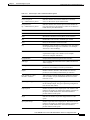
Table 4-18 describes the fields shown in the show interface cable upstream display.
Cisco uBR7200 Series Universal Broadband Router Software Configuration Guide
78-5897-01
4-27
Chapter 4
Troubleshooting the System
Understanding Show Command Responses
Table 4-18
Show Interface Cable Upstream Command Field Descriptions
Field
Description
Cable
Indicates the location of the upstream interface
Upstream is
up/...administratively down
Indicates the administrative state of the upstream interface
Received broadcasts
Number of broadcast packets received through this
upstream interface
multicasts
Number of multicast packets received through this
upstream interface
unicasts
Number of unicast packets received through this interface
discards
Number of packets discarded by this interface
errors
Sum of all errors that prevented upstream transmission of
packets through this interface
unknown protocol
Number of packets received that were generated using a
protocol unknown to the Cisco uBR7246
packets input
Number of packets received through this upstream
interface that were free from errors
corrected
Number of error packets received through this upstream
interface that were corrected
uncorrectable
Number of error packets received through this upstream
interface that could not be corrected
noise
Number of upstream packets corrupted by line noise
microreflections
Number of upstream packets corrupted by
microreflections
Guaranteed-rate service queue
depth
Number of bandwidth requests queued up in the
Guarantee-rate queue. This queue is only available to
modems that have a reserved minimum upstream rate in
their Class of Service
Best-effort service queue depth
Number of bandwidth requests queued up in the
Best-effort queue. This queue is available to all modems
that do not have any reserved rate on the upstream
Total Modems On This
Upstream Channel
Number of cable modems currently sharing this upstream
channel. This field also shows how many of these modems
are active
Current Total Bandwidth
Reserved
Total amount of bandwidth reserved by all modems
sharing this upstream channel that require bandwidth
reservation. The Class of Service for these modems
specifies some non-zero value for the guaranteed-upstream
rate. When one of these modems is admitted on the
upstream, this field value is incremented by this
guaranteed-upstream rate value
Cisco uBR7200 Series Universal Broadband Router Software Configuration Guide
4-28
78-5897-01
Chapter 4
Troubleshooting the System
Understanding Show Command Responses
Table 4-18
Show Interface Cable Upstream Command Field Descriptions (continued)
Field
Description
CIR admission control
(formerly: Current Admission
Control Status)
Indicates the status of admission control on the upstream
channel
ENFORCED status allows users to enable admission
control on a per port basis. This controls how limited
bandwidth is allocated. NOT ENFORCED status indicates
that there is no admission control. Every modem that
registers with a class of service specifying a minimum
upstream rate will be admitted by the CMTS regardless of
how much aggregate bandwidth is actually available.
Users enable admission control by using the admission
control CLI
Default MAC scheduler
Indicates the status of the MAC scheduler as being in
default mode as opposed to Automated Test Procedure
(ATP)
Queue[Rng Polls]
The MAC scheduler queue showing the number of ranging
polls
Queue[Cont Mslos]
The MAC scheduler queue showing the number of forced
contention request slots in MAPS
Queue[CIR Grants]
The MAC scheduler queue showing the number of CIR
grants pending
Queue[BE Grants]
The MAC scheduler queue showing the number of BE
grants pending
Queue[Grant Shpr]
The MAC scheduler queue showing the number of grants
that have been buffered for traffic shaping
drops
Number of packets dropped
Reserved slot table currently has
0 CBR entries
Number of CBR sessions active on an upstream channel at
any given time
Req IEs
The running counter of request IEs sent in MAPS
Req/Data IEs
The counter of request/data IEs sent in MAPS
Init Mtn IEs
The counter of Initial Maintenance IEs
Stn Mtn IEs
Number of station maintenance (ranging poll) IEs
Long Grant IEs
Number of long grant IEs
Short Grant IEs
Number of short grant IEs
Avg upstream channel
utilization
Indicates on average what percent of the upstream channel
bandwidth is being used
Avg percent contention slots
Indicates on average what percent of slots are in
contention state
Avg percent initial ranging slots Indicates on average what percent of slots are in initial
ranging state
Cisco uBR7200 Series Universal Broadband Router Software Configuration Guide
78-5897-01
4-29
Chapter 4
Troubleshooting the System
Understanding Show Command Responses
Table 4-18
Show Interface Cable Upstream Command Field Descriptions (continued)
Field
Description
Avg percent minislots lost on
late MAPs
Indicates on average what percent of slots are lost because
a MAP interrupt was too late
Current minislot count
(formerly: Last Minislot Stamp
(current_time_base))
Indicates the current minislot count at the CMTS. FLAG
indicates the timebase reference. This field is used only by
developers.
Scheduled minislot count
(formerly: Last Minislot Stamp
(scheduler_time_base))
Indicates the furthest minislot count allocated at the
indicated time. FLAG indicates the timebase reference.
This field is used only by developers.
Enhanced Show Interface Upstream Output
The show interface cable upstream command is enhanced in Cisco IOS Release 12.0(7)XR2,
Cisco IOS Release 12.1(1a)T1, or higher CMTS images to display detailed MAC scheduler state
information for the upstream port. The example below illustrates the new display:
cmts#show interface cable 3/0 upstream 0
Cable3/0:Upstream 0 is up
Received 13 broadcasts, 0 multicasts, 110 unicasts
0 discards, 106 errors, 0 unknown protocol
123 packets input, 0 uncorrectable
106 noise, 0 microreflections
Total Modems On This Upstream Channel :3 (3 active)
Default MAC scheduler
Queue[Rng Polls] 0/20, fifo queueing, 0 drops
Queue[Cont Mslots] 0/104, fifo queueing, 0 drops
Queue[CIR Grants] 0/20, fair queueing, 0 drops
Queue[BE Grants] 0/30, fair queueing, 0 drops
Queue[Grant Shpr]
0/30, calendar queueing, 0 drops
Reserved slot table currently has 2 CBR entries
Req IEs 280185, Req/Data IEs 0
Init Mtn IEs 800, Stn Mtn IEs 49
Long Grant IEs 26, Short Grant IEs 15
Avg upstream channel utilization :1%
Avg percent contention slots :97%
Avg percent initial ranging slots :1%
Avg percent minislots lost on late MAPs :0%
Total channel bw reserved 192000 bps
CIR admission control not enforced
Current minislot count
:1165412
Flag:1
Scheduled minislot count :1176227
Flag:1
New items in the display include:
•
Detailed slot queue statistics---Queue [CIR Grants] 0/20, fair queueing, 0 drops in the example
above means that the queue for CIR-service grants has a current depth of 0, a maximum depth of
20. Weighted fair queueing shows grants in this queue.
•
CBR slot scheduling table state---The above reserved slot table has 2 CBR entries. This shows that
at the time the command was issued, the MAC scheduler had admitted 2 CBR slots in the reserved
slot table.
Cisco uBR7200 Series Universal Broadband Router Software Configuration Guide
4-30
78-5897-01
Chapter 4
Troubleshooting the System
Understanding Show Command Responses
•
Counters for each type of upstream slot scheduled in the MAPs for this upstream channel---The
“Init Mtn IEs 800” means that the MAC scheduler has added 800 initial maintenance information
elements (slots) at the time the show command was issued.
•
MAC scheduling statistics to display what percentage of the upstream bandwidth is utilized for
each type of slot on an average.
Show Interface Cable SID
To display per-SID counters for bandwidth requests, use the show interface cable privileged EXEC
command: show interface cable interface sid [sid] counters verbose. Data transport over the RF link
uses the registered SID address, rather than the Ethernet address. This allows multiple hosts to access
the network by using a single cable modem.
Note
Cisco IOS Release 12.0(7)XR2 and 12.1(1a)T1 adds the verbose option to provide SID
details.
See the following display output for the verbose keyword extension for SID 1 on interface
cable slot 3, port 0:
router# show interface c3/0 sid
Sid
Input packets
Input octets
Output packets
Output octets
BW requests received
Grants issued
Rate exceeded BW request drops
Rate exceeded DS packet drops
1
:
:
:
:
:
:
:
:
:
counters verbose
1
39
15964
30
8796
40
40
0
0
Cisco uBR7200 Series Universal Broadband Router Software Configuration Guide
78-5897-01
4-31
Chapter 4
Troubleshooting the System
Understanding Show Command Responses
See the following display output for the verbose keyword extension for all SIDs on the specified
interface:
router# show interface c3/0 sid counters verbose
Sid
: 1
Input packets
: 39
Input octets
: 15964
Output packets
: 30
Output octets
: 8796
BW requests received
: 40
Grants issued
: 40
Rate exceeded BW request drops : 0
Rate exceeded DS packet drops : 0
Sid
: 2
Input packets
: 0
Input octets
: 0
Output packets
: 0
Output octets
: 0
BW requests received
: 0
Grants issued
: 0
Rate exceeded BW request drops : 0
Rate exceeded DS packet drops : 0
Sid
: 3
Input packets
: 0
Input octets
: 0
Output packets
: 0
Output octets
: 0
BW requests received
: 0
Grants issued
: 0
Rate exceeded BW request drops : 0
Rate exceeded DS packet drops : 0
See the following display for the SIDs connected to the specified interface:
Lab-CMTS#
Sid Prim
Sid
23
24
25
26
27
28
29
30
show inter cab 3/0 sid
Type Online
Admin
State
Status
stat init(d)
enable
stat init(d)
enable
stat init(rc)
enable
stat init(d)
enable
stat offline
enable
stat offline
enable
stat offline
enable
dyn init(o)
enable
QoS Create
Time
2
04:00:54
2
04:00:58
2
04:01:05
2
04:01:10
2
04:01:31
2
04:01:59
2
04:02:07
2
04:03:09
IP Address
MAC Address
209.165.200.0
209.165.200.0
209.165.200.0
209.165.200.0
209.165.200.225
209.165.200.226
209.165.200.227
209.165.200.228
0050.7366.17ab
0050.7366.1803
00d0.bad3.c459
0050.7366.1801
0090.8330.0213
0090.8330.0211
0090.8330.0214
0090.833
See the following connection information for all SIDs on the specified interface:
router# show interface c3/0 sid connectivity
Sid
1st time
Times %online
Online time
online
Online
min
avg
max
1
15:37:24
1
99.73
00:00
1h45m
1h45m
2
15:37:24
1
99.73
00:00
1h45m
1h45m
3
15:37:24
1
99.73
00:00
1h45m
1h45m
Offline time
min
avg
max
00:17
00:17
00:17
00:17
00:17
00:17
00:17
00:17
00:17
See the following connection information for SID 1 on the specified interface:
router# show interface c3/0 sid 1 connectivity
Sid
1st time
Times %online
Online time
online
Online
min
avg
max
1
15:37:24
1
99.72
00:00
1h41m
1h41m
Offline time
min
avg
max
00:17
00:17
00:17
Cisco uBR7200 Series Universal Broadband Router Software Configuration Guide
4-32
78-5897-01
Chapter 4
Troubleshooting the System
Understanding Show Command Responses
See the following display for the counters of the SIDs connected to the specified interface:
router# show interface c3/0 sid counters
Sid
Inpackets Inoctets
Outpackets Outoctets
1
2
3
40
0
0
16586
0
0
31
0
0
9160
0
0
Ratelimit
BWReqDrop
0
0
0
Ratelimit
DSPktDrop
0
0
0
See the following display for the counters of SID 1 on the specified interface:
router# show interface c3/0 sid 1 counters
Sid
Inpackets Inoctets
Outpackets Outoctets
1
39
15964
30
8796
Ratelimit
BWReqDrop
0
Ratelimit
DSPktDrop
0
Table 4-19 describes the fields shown in the output for the show interface cable sid displays.
Table 4-19
show interface cable sid Command Field Descriptions
Field
Description
Sid
Service identification number
Prim Sid
The primary service identifier assigned to the modem
Type
Indicates this SID was created statically at the time of registration
or dynamically by the exchange of dynamic service messages
between the CM and CMTS
Online State
“Online” means the modem owning this SID is processing traffic.
“Offline” means the modem owning this SID is not processing
traffic
Admin Status
“Disable” means that the SID has been turned off. “Enable” is the
normal state
QoS
Quality of service.
Create time
When the SID was created, number of seconds since the system
booted
Input octets (Inoctets)
Number of octets received by using this SID
Input packets (Inpackets)
Number of packets received by using this SID
Output octets (Outoctets)
Number of octets sent from this SID
Output packets
(Outpackets)
Number of packets sent from this SID
IP address
IP address of the modem owning this SID
MAC address
MAC address of the modem owning this SID
BW requests received
Number of bandwidth requests received by this SID
Grants issued
Number of bandwidth requests granted by this SID
Rate exceeded BW
request drops
Number of bandwidth requests not granted by this SID
Cisco uBR7200 Series Universal Broadband Router Software Configuration Guide
78-5897-01
4-33
Chapter 4
Troubleshooting the System
Troubleshooting Using Cable Flap Lists
Table 4-19
show interface cable sid Command Field Descriptions (continued)
Field
Description
Rate exceeded DS packet
drops
Number of downstream packets lost by this SID
Ratelimit BWReqDrop
Number of bandwidth requests not granted by this SID
Ratelimit DSPktDrop
Number of downstream packets lost by this SID
1st time online
Time at which the modem with this SID connected
Times online
Number of times the modem with this SID has connected
% online
Percentage of time the modem with this SID has been connected
Online time
The minimum, average, and maximum number of hours and
minutes the modem with this SID has been connected
Offline time
The minimum, average, and maximum number of hours and
minutes the modem with this SID has been disconnected
Show Cable QoS Profile
Following is a response to the show cable qos profile command. The display shows ToS specifications:
uBR7200#show cable qos profile
Service
class
>
1
2
3
4
5
6
Note
Prio Max
Guarantee Max
Max tx
upstream upstream downstream burst
bandwidth bandwidth bandwidth
0
0
0
0
0
0
64000
0
1000000
0
0
1000
0
1000
0
3
256000
0
512000
0
5
1000000
0
10000000
0
3
256000
0
512000
0
TOS TOS
Create
mask value by
0x0
0x0
0x0
0x0
0x0
0x0
0x0
0x0
0x0
0x0
0x0
0x0
cmts(r)
cmts(r)
cmts
cm
cm
cm
B
priv
enab
no
no
no
no
no
yes
The “r” in the “Create by” column means the first two classes of service the CMTS creates
are reserved for CMs that are not online.
Displays upstream packet discards, errors, error-free packets, correctable and uncorrectable errors,
noise and microreflection statistics:
show
interface slot/downstream-port upstream
Troubleshooting Using Cable Flap Lists
The Cisco uBR7200 series universal broadband routers maintain a database of flapping cable modems
to assist in locating cable plant problems. The flapping cable modem detector tracks the upstream and
downstream performance of all cable modems on the network, without impacting throughput and
performance, or creating additional packet overhead on the broadband network. The cable modem flap
Cisco uBR7200 Series Universal Broadband Router Software Configuration Guide
4-34
78-5897-01
Chapter 4
Troubleshooting the System
Troubleshooting Using Cable Flap Lists
list keeps track of the cable modem MAC address, up and down transitions, registration events, missed
periodic ranging packets, upstream power adjustments and the physical interface on the
Cisco uBR7200 series.
Note
Although this is a Cisco proprietary CMTS feature, it is compatible with all
DOCSIS-compliant cable modems. Unlike SNMP, the flap list uses zero bandwidth.
The flap list collects the following station maintenance statistics:
•
Detects interface up/down flap; the reinsertion counter counts the number of times a cable modem
comes up and inserts into the network. This helps identify potential problems in the downstream
because improperly provisioned cable modems tend to try to reestablish a link repeatedly.
•
Detects intermittent upstream; the keepalive hits versus misses is the number of times cable
modems don’t respond or don’t respond to the MAC layer keepalive messages. If there are a number
of misses, this points to a potential problem in the upstream.
•
Lists cable modem MAC addresses sorted by flap rate or most recent flap time.
•
Shows power adjustment statistics during station maintenance polling; this represents the number
of times the CMTS tells a cable modem to adjust the transmit power more than 3 dB. If constant
power adjustments are detected, this usually indicates a problem with an amplifier. By looking at
the cable modems in front and behind various amplifiers, you can find the source of failure.
The cable system administrator typically:
•
Sets up a script to periodically poll the flap list, for example, every 15 minutes
•
Uses the resulting data to perform trend analysis to identify the cable modems that are consistently
in the flap list
•
Queries the billing and administrative database for cable modem MAC address-to-street address
translation and generates a report
These reports can be given to the Customer Service Department or the cable plant’s Operations and
Maintenance Department. Using these reports, maintenance personnel can quickly discern how
characteristic patterns of flapping cable modems, street addresses, and flap statistics can indicate which
amplifier or feeder lines are faulty. The reports also help you quickly discern whether problems exist in
your downstream or upstream path, and whether the problem is ingress noise or equipment related.
Default values for the following flap-list configuration commands are:
Note
•
cable flap-list miss-threshold—6 seconds
•
cable flap-list power-adjust—2 dB
•
cable flap-list insertion-time—180 seconds
Since the cable flap list was originally developed, polling mechanisms have been enhanced
since Cisco IOS Release 11.3.7 NA to have an increased rate of 1/sec when polls are
missed. Cable modems go offline faster than the frequency hop period. This can cause the
frequency to stay fixed while cable modems go offline. To compensate for this, as
appropriate, you can reduce the hop period to 10 seconds.
Cisco uBR7200 Series Universal Broadband Router Software Configuration Guide
78-5897-01
4-35
Chapter 4
Troubleshooting the System
Troubleshooting Using Cable Flap Lists
Tips
In Cisco IOS Release 12.0(7)XR2, Cisco IOS Release 12.1(1a)T1, and higher, the system
supports automatic power adjustments. The show cable flap-list and show cable modem
commands now indicate when the Cisco uBR7200 series router has detected an unstable
return path for a particular modem and has compensated with a power adjustment. An
asterisk appears in the power adjustment field for a modem when a power adjustment has
been made; an exclamation point appears when the modem has reached its maximum
power transmit level and cannot increase its power level any further.
The following tips and scenarios allow you to use the flap list in the most effective way:
•
If a subscriber's cable modem shows a lot of flap list activity, it is having communication problems.
•
If a subscriber's cable modem shows little or no flap list activity, it is communicating reliably; the
problem is probably in the subscriber's computer equipment or in the connection to the
cable modem.
•
The top 10% most active cable modems in the flap list are most likely to have difficulties
communicating with the headend.
•
Cable modems with more than 50 power adjustments per day have a suspect upstream path.
•
Cable modems with approximately the same number of hits and misses and with a lot of insertions
have a suspect downstream path (for example, low level into the cable modem).
•
All cable modems incrementing the insertion at the same time indicates a provisioning server
failure.
•
Cable modems with high CRC errors have bad upstream paths or in-home wiring problems.
•
Correlating cable modems on the same physical upstream port with similar flap list statistics can
quickly resolve outside plant problems to a particular node or geography.
•
Monitoring the flap list cannot affect cable modem communications.
•
The flap list should be saved to a database computer and cleared at least once a day.
•
Important upstream performance data can be obtained by tracking flap list trend data.
•
Important installation quality control and performance data is directly available from the flap list.
Cisco uBR7200 Series Universal Broadband Router Software Configuration Guide
4-36
78-5897-01
Chapter 4
Troubleshooting the System
Troubleshooting Using Cable Flap Lists
Following is a sample response to the show cable flap command:
uBR7200#show cable flap
Mac Addr
0010.9500.461f
0010.9500.446e
0010.9500.38ec
0010.9500.4474
0010.9500.4672
0010.9500.38f0
0010.9500.e8cb
0010.9500.38f6
0010.9500.4671
0010.9500.38eb
0010.9500.3ce2
0010.9500.e8d0
0010.9500.4674
0010.9500.4677
0010.9500.4614
0010.9500.3be9
0010.9500.4609
0010.9500.3cb8
0010.9500.460d
0010.9500.3cba
0010.9500.3cb4
0010.9500.4612
CableIF
C3/0 U1
C3/0 U1
C3/0 U2
C3/0 U2
C3/0 U2
C3/0 U2
C3/0 U2
C3/0 U3
C3/0 U4
C4/0 U0
C4/0 U0
C4/0 U2
C4/0 U4
C4/0 U4
C5/0 U5
C6/0 U5
C6/0 U5
C6/0 U5
C6/0 U5
C6/0 U5
C6/0 U5
C6/0 U5
Ins
56
38
63
65
56
50
0
50
43
57
44
0
56
40
40
63
55
49
46
39
38
38
Hit
18857
18686
18932
18913
18990
18964
6537
19016
18755
36133
35315
13213
36037
35781
21810
22862
22723
22607
22477
22343
22238
22306
Miss
887
2935
1040
1053
2327
2083
183
2511
3212
1608
1907
246
2379
2381
2362
969
2127
1378
2967
3058
2936
2928
CRC
0
0
0
0
0
0
0
0
1
0
0
0
0
0
0
0
0
0
0
0
0
0
P-Adj
1
1
8
3
6
5
1
2
1
6
4
1
4
4
502
0
0
0
2
0
0
0
Flap
116
80
138
137
124
111
5
104
89
126
99
5
121
91
586
128
112
102
96
81
79
79
Time
1 14:09:12
2 19:03:57
2 23:50:53
2 09:30:09
2 10:44:14
2 20:46:56
2 22:35:48
2 07:46:31
1 19:36:20
2 20:04:58
2 16:42:47
3 04:15:30
3 00:34:12
2 12:14:38
2 21:43:02
1 14:09:03
1 14:08:02
1 14:08:58
2 17:03:48
1 14:13:16
1 14:09:26
1 14:09:29
Jun
Jun
Jun
Jun
Jun
Jun
Jun
Jun
Jun
Jun
Jun
Jun
Jun
Jun
Jun
Jun
Jun
Jun
Jun
Jun
Jun
Jun
The command line with an arrow next to it reveals a cable modem that is continuously flapping. A high
flap rate indicates that the cable modem is power adjusting frequently. This can indicate a problem with
an amplifier. The number reveals the number of times the CMTS instructed the cable modem to adjust
the transmit power more than 3 dB.
Cable modems are automatically added to the flap list when any of the following conditions are
detected:
•
When the cable modem re-registers more frequently than the user-specified insertion time.
•
When intermittent keepalive messages are detected between the CMTS and the cable modem.
•
When the cable modem’s upstream transmit power is adjusted beyond the user-specified power
threshold.
Display the Flap List
The flap list can be queried either using the standard Simple Network Management (SNMP) API or the
CLI. Using any third party SNMP Management Information Base (MIB) browser, you can query the
ccsFlapTable in the CISCO-CABLE-SPECTRUM-MIB, a proprietary extension to the DOCSIS MIBs.
Using the show cable flap list command, the flap list statistics are accessed. A sample appears below.
Each of the columns in the display are described in Table 4-20:
MAC ID___ CableIF
0010.7b6b.60ad C3/0 U0
0010.7b6b.65a3 C3/0 U0
0010.7b6b.6b9d C3/0 U0
Ins _Hit__
Miss
0 14386
1390
0 14503
1264
0 14060
1726
CRC
1
1
3
P-Adj
38
33
40
Flap ___Time____
41
Nov 24 21:34:24
37
Nov 24 21:28:09
43
Nov 24 21:18:36
Cisco uBR7200 Series Universal Broadband Router Software Configuration Guide
78-5897-01
4-37
Chapter 4
Troubleshooting the System
Troubleshooting Using Cable Flap Lists
Table 4-20
Flap List Statistics Description
Statistic
Description
MAC ID
This is the MAC-layer address of a cable modem. The first six digits indicate the vendor ID of
the cable modem manufacturer, followed by six digits indicating a unique host address. Each
cable modem's MAC address is unique.
Cable IF
This is the physical upstream interface on the Cisco uBR7200. It denotes the cable modem card
slot number, the downstream port number on the RF line card and the upstream port number on
the same cable modem card. The flap list data can be sorted based on the upstream port number
which is useful when isolating reverse path problems unique to certain combining groups.
Insertions
Link insertion is the process whereby a modem performs an initial maintenance procedure to
establish link with the CMTS. The Ins column is the flapping modem’s insertion count and
indicates the number of times the RF link was abnormally re-established. An abnormality is
detected when the time between link re-establishment attempts is less than the user-configurable
parameter.
Normal modem activity follows the sequence below.
•
The initial link insertion is followed by a keepalive loop between the CMTS and cable
modem and is called station maintenance.
•
Power-on
•
Initial maintenance
•
Station maintenance
•
Power-off
When the link is broken, initial maintenance is repeated to re-establish the link.
Initial maintenance @ Time T1
Station maintenance
Init maintenance
@ Time T2
The Ins and Flap counters in the flap list are incremented whenever T2 – T1 < N where N is the
insertion-time parameter configured in <cable flap-list insertion-time>. Default value for this
parameter is TBD seconds.
A high Ins number indicates:
•
Intermittent downstream sync loss
•
DHCP or modem registration problems
Cisco uBR7200 Series Universal Broadband Router Software Configuration Guide
4-38
78-5897-01
Chapter 4
Troubleshooting the System
Troubleshooting Using Cable Flap Lists
Table 4-20
Flap List Statistics Description
Hit and Miss
The HIT and MISS columns are keepalive polling statistics between the Cisco uBR7200 series
and the cable modem. The station maintenance process occurs for every modem approximately
every 25 seconds. When the CMTS receives a response from the modem, the event is counted as
a Hit. If the CMTS does not receive a response from the cable modem, the event is counted as a
Miss. A cable modem will fail to respond either because of noise or if it is down. Modems which
only log Misses and zero Hits are assumed to be powered off.
Misses are not desirable since this is usually an indication of a return path problem; however,
having a small number of misses is normal. The flap count is incremented if there are M
consecutive misses where M is configured in the cable flap miss-threshold parameter. The
parameter value ranges from 1 to 12 with a default of 6.
Ideally, the HIT count should be much greater than the Miss counts. If a modem has a HIT count
much less than its MISS count, then registration is failing. Noisy links cause the MISS/HIT ratio
to deviate from a nominal 1% or less. High Miss counts can indicate:
•
Intermittent upstream possibly due to noise
•
Laser clipping
•
Common-path distortion
•
Ingress or interference
•
Too much or too little upstream attenuation
Cyclical
This statistic tracks the CRC error counter per modem. CRC errors are usually an indication of
Redundancy Check noise on a plant. A low count can be always be expected but a high CRC number calls for some
(CRC)
the plant troubleshooting. The CRC counter indicates:
Power
Adjustments
(P-Adj)
•
Intermittent upstream
•
Laser clipping
•
Common-path distortion
•
Impulsive noise or interference
The station maintenance poll in the CMTS constantly adjusts the modem transmit power,
frequency, and timing. The P-Adj column indicates the number of times the modem’s power
adjustment exceeded the threshold value. The power adjustment threshold may be set using the
<cable flap power threshold > parameter with a value range of 0 to 10 dB and a default value of
2 dB. Tuning this threshold is recommended to decrease irrelevant entries in the flap list. Power
Adjustment values of 2 dB and below will continuously increment the P-Adj counter. The
modem transmitter step size is 1.5 dB, whereas the headend may command 0.25 dB step sizes.
Power adjustment flap strongly suggests upstream plant problems such as:
•
Amplifier degradation
•
Poor connections
•
Thermal sensitivity
•
Attenuation problem
Cisco uBR7200 Series Universal Broadband Router Software Configuration Guide
78-5897-01
4-39
Chapter 4
Troubleshooting the System
Troubleshooting Using Cable Flap Lists
Table 4-20
Flap
Flap List Statistics Description
The Flap counter indicates the number of times the modem has flapped. This counter is
incremented when one of the following events is detected:
Unusual modem insertion or reregistration attempts. The Flap and the Ins counters are
incremented when the modem tries to reestablish the RF link with the CMTS within a period of
time that is less than the user-configurable insertion interval value.
Abnormal Miss/Hit ratio The Flap counter is incremented when N consecutive Misses are
detected after a Hit where N can be user-configurable with a default value of 6.
Unusual power adjustment The Flap and P-adj counters are incremented when the modem’s
upstream power is adjusted beyond a user-configurable power level.
Time
Time is the timestamp indicating the last time the modem flapped. The value is based on the
clock configured on the local Cisco uBR7200 series. If no time is configured, this value is based
on the current uptime of the Cisco uBR7200 series. When a modem meets one of the three flap
list criteria, the Flap counter is incremented and Time is set to the current time.
Troubleshoot with the Flap List
This section includes suggestions on how to interpret different network conditions based on the flap list
statistics:
•
Condition 1: Low miss/hit ratio (< 10% for MC11 card, < 2% for MC16 card), low insertion, low
P-adj, low flap counter and old timestamp.
Analysis: This exhibits an optimal network situation.
•
Condition 2: High ratio of misses over hits (> 10%)
Analysis: Hit/miss analysis should be done after the "Ins" count stops incrementing. In general, if
the hit and miss counts are about the same order of magnitude, then the upstream may be
experiencing noise. If the miss count is greater, then the modem is probably dropping out frequently
and not completing registration. The upstream or downstream is perhaps not stable enough for
reliable link establishment. Very low hits and miss counters and high insertion counters indicate
provisioning problems.
•
Condition 3: Relatively high power adjustment counter.
Analysis: Indicates the power adjustment threshold is probably set at default value of 2 dB
adjustment. The modem transmitter step size is 1.5 dB, whereas the headend may command
0.25 dB step sizes. Tuning your power threshold to 6 dB is recommended to decrease irrelevant
entries in the flap list. The power adjustment threshold may be set using <cable flap power
threshold <0-10 dB>> from the Cisco IOS global configuration mode. A properly operating HFC
network with short amplifier cascades can use a 2-3 dB threshold.
•
Condition 4: High P-Adj and CRC errors.
Analysis: This condition can indicate that the fiber node is clipping the upstream return laser.
Evaluate the modems with the highest CRC count first. If the modems are not going offline
(Ins = 0), this will not be noticed by the subscriber. However, they could receive slower service due
to dropped IP packets in the upstream. This condition will also result in input errors on the
Cisco uBR7200 series cable interface.
•
Condition 5: High insertion rate.
Analysis: If link re-establishment happens too frequently, then the modem is usually having a
registration problem.This is indicated by a high ‘Ins’ counter which tracks the ‘Flap’ counter.
Cisco uBR7200 Series Universal Broadband Router Software Configuration Guide
4-40
78-5897-01
Chapter 4
Troubleshooting the System
Troubleshooting Using Cable Flap Lists
Set Cable Flap List Aging
You can specify the number of days to record and retain flapping activity on cable modems currently in
the flap-list table. This value is known as the age of the flap list. The valid range is from 1 to 60 days.
To set the age of the flap list, use the following command in global configuration mode.
Table 4-21
Instructions to Set Cable Flap List Aging
Command
Purpose
CMTS01(config)# cable flap-list aging days
Specify the number of days to record and retain
flapping activity for the cable modems connected to
this Cisco uBR7200 series.
Verify Cable Flap List Aging
To verify that cable flap list aging is set, enter the show cable flap list command:
CMTS01# show cable flap list
Mac Addr
CableIF
Ins
0010.7b6b.5d1d C3/0 U0
0
0010.7b6b.5e15 C3/0 U0
1
0010.7b6b.5e27 C3/0 U0
1
0010.7b6b.5d29 C3/0 U0
1
0010.7b6b.5e2b C3/0 U0
1
Hit
688
707
707
709
710
Miss
169
185
198
205
204
CRC
0
0
0
0
0
P-Adj
0
0
0
0
0
Flap
3
5
5
5
7
Time
5 12:28:50
5 12:29:52
5 12:29:55
5 12:29:52
5 12:30:16
Nov
Nov
Nov
Nov
Nov
Set Cable Flap List Insertion Time
You can set the cable flap list insertion time. When a cable modem makes an insertion request more
frequently than the amount of insertion time defined by this command, the cable modem is placed in
the flap list for activity recording. The valid range is from 60 to 86400 seconds.
To set the cable flap list insertion time, use the following command in global configuration mode.
Table 4-22
Instructions to Set Cable Flap List Insertion Time
Command
Purpose
CMTS01(config)# cable flap-list insertion-time seconds
Specify the insertion time in seconds. Any cable
modem that makes an insertion request more
frequently than this period of time is placed in the
flap list.
Verify Cable Flap List Insertion Time
To verify cable flap list insertion time, enter the show cable flap list command:
CMTS01# show cable flap list
Mac Addr
CableIF
Ins
0010.7b6b.5d1d C3/0 U0
0
0010.7b6b.5e15 C3/0 U0
1
0010.7b6b.5e27 C3/0 U0
1
0010.7b6b.5d29 C3/0 U0
1
0010.7b6b.5e2b C3/0 U0
1
Hit
688
707
707
709
710
Miss
169
185
198
205
204
CRC
0
0
0
0
0
P-Adj
0
0
0
0
0
Flap
3
5
5
5
7
Time
5 12:28:50
5 12:29:52
5 12:29:55
5 12:29:52
5 12:30:16
Nov
Nov
Nov
Nov
Nov
Cisco uBR7200 Series Universal Broadband Router Software Configuration Guide
78-5897-01
4-41
Chapter 4
Troubleshooting the System
Troubleshooting Using Cable Flap Lists
Set Cable Flap List Power Adjustment Threshold
You can specify the power adjustment threshold that will cause a flap-list event to be recorded. When
the power adjustment of a cable modem meets or exceeds the threshold, the cable modem is placed in
the flap list. The valid range is from 1 to 10 dBmV.
Note
A power adjustment threshold of less than 2 dBmV might cause excessive flap list event
recording. Cisco recommends setting this threshold value to 3 dBmV or higher.
To set the power adjustment threshold for flap-list events, use the following command in global
configuration mode.
Table 4-23
Instruction to Set Cable Flap List Power Adjustment Threshold
Command
Purpose
CMTS01(config)# cable flap-list power-adjust threshold dbmv
Specify the minimum power adjustment that will
constitute a flap-list event.
Verify Cable Flap List Power Adjustment Threshold
To verify the cable flap list power adjustment threshold, enter the show cable flap list command:
CMTS01# show cable flap list
Mac Addr
CableIF
Ins
0010.7b6b.5d1d C3/0 U0
0
0010.7b6b.5e15 C3/0 U0
1
0010.7b6b.5e27 C3/0 U0
1
0010.7b6b.5d29 C3/0 U0
1
0010.7b6b.5e2b C3/0 U0
1
Hit
688
707
707
709
710
Miss
169
185
198
205
204
CRC
0
0
0
0
0
P-Adj
0
0
0
0
0
Flap
3
5
5
5
7
Time
5 12:28:50
5 12:29:52
5 12:29:55
5 12:29:52
5 12:30:16
Nov
Nov
Nov
Nov
Nov
Set Cable Flap List Miss Threshold
You can specify the miss threshold for recording a flap-list event. A miss is the number of times a
cable modem does not acknowledge a MAC layer keepalive message from a cable modem card. An 8%
miss rate is normal for the Cisco cable modem cards. When the number of misses exceeds the threshold,
the cable modem is placed in the flap list.
Note
A high miss rate can indicate intermittent upstream problems, fiber laser clipping, or
common-path distortion.
To set the miss threshold for recording a flap-list event, use the following command in global
configuration mode.
Table 4-24
Instructions to Set Cable Flap List Miss Threshold
Command
Purpose
CMTS01(config)# cable flap-list miss-threshold misses
Specify the number of MAC-layer keepalive misses
that will result in the cable modems being place in
the flap list.
Cisco uBR7200 Series Universal Broadband Router Software Configuration Guide
4-42
78-5897-01
Chapter 4
Troubleshooting the System
Troubleshooting Using Cable Flap Lists
Verify Cable Flap List Miss Threshold
To verify the cable flap list miss threshold, enter the show cable flap list command:
CMTS01# show cable flap list
Mac Addr
CableIF
Ins
0010.7b6b.5d1d C3/0 U0
0
0010.7b6b.5e15 C3/0 U0
1
0010.7b6b.5e27 C3/0 U0
1
0010.7b6b.5d29 C3/0 U0
1
0010.7b6b.5e2b C3/0 U0
1
Hit
688
707
707
709
710
Miss
169
185
198
205
204
CRC
0
0
0
0
0
P-Adj
0
0
0
0
0
Flap
3
5
5
5
7
Time
5 12:28:50
5 12:29:52
5 12:29:55
5 12:29:52
5 12:30:16
Nov
Nov
Nov
Nov
Nov
Set Cable Flap List Size
You can specify the maximum number of cable modems that can be listed in the cable flap list tables.
The valid range is from 1 to 8192 cable modems. The default is 8192 cable modems.
To specify the maximum number of cable modems that can be recorded in the flap list, use the following
command in global configuration mode.
Table 4-25
Instructions to Set Cable Flap List Size
Command
Purpose
CMTS01(config)# cable flap-list size number
Specify the maximum size of the flap list.
Verify Cable Flap List Size
To verify the cable flap list size, enter the show cable flap list command:
CMTS01# show cable flap list
Mac Addr
CableIF
Ins
0010.7b6b.5d1d C3/0 U0
0
0010.7b6b.5e15 C3/0 U0
1
0010.7b6b.5e27 C3/0 U0
1
0010.7b6b.5d29 C3/0 U0
1
0010.7b6b.5e2b C3/0 U0
1
Hit
688
707
707
709
710
Miss
169
185
198
205
204
CRC
0
0
0
0
0
P-Adj
0
0
0
0
0
Flap
3
5
5
5
7
Time
5 12:28:50
5 12:29:52
5 12:29:55
5 12:29:52
5 12:30:16
Nov
Nov
Nov
Nov
Nov
Clear Cable Flap List
To remove a single cable modem from the flap list or to remove all cable modems from the flap list, use
one of the following commands in global configuration mode.
Table 4-26
Instructions to Clear Cable Flap List
Command
Purpose
CMTS01(config)# clear cable flap-list mac-addr
Clear the entries in the cable flap list for the cable
modem with this MAC address.
CMTS01(config)# clear cable flap-list all
Clear the entries for all of the cable modems in the
flap list.
Cisco uBR7200 Series Universal Broadband Router Software Configuration Guide
78-5897-01
4-43
Chapter 4
Troubleshooting the System
Troubleshooting Using Cable Flap Lists
Customize Other Flap List Values and Related Commands
The following displays flap list with different sorting options:
show cable modem flap-list [cable <n> | sort-flap | sort-time | sort-interface]
The following sets the threshold value for link establishment:
[no] cable flap-list insertion-time <sec>
Note
A modem is tagged as flapping if the insertion time exceeds this value. Its value can be set
from 60 to 86400 seconds with a default of 180 seconds.
The following sets the number of consecutive missed station maintenance(RNG-RSP) messages that
must be missed for a ‘flap’ event to occur. Value ranges from 1-12 with a default of 6 seconds. The hits
and miss counters are not affected:
[no] cable flap-list miss-threshold <miss-threshold>
The following clears the counters for a cable modem (or all cable modems) in the station maintenance
list:
clear cable modem { <mac-addr> | <ip-addr> | all } counters
The following displays the QoS, modem status, In and Out octets, IP and MAC addresses per SID:
show int cable slot/port sid
The following drops the modem's RF link by removing a modem from the keep-alive polling list. This
forces the modem to reset:
clear cable-modem { <mac-addr> | <ip-addr> | all } reset
The following uses a MAC layer ping to determine if the cable modem is online. It uses smaller data
units on the wire than a standard IP ping, resulting in lower overhead. Works even if the IP layer in the
modem is down or hasn’t completed registration:
ping DOCSIS cable-modem <mac-addr | IP address >
The following displays the timing offset, receive power, and QoS values by cable interface, SID, and
MAC address:
show cable modem [<ip-address> | <MAC-address>]
The following displays the current allocation table and frequency assignments:
show cable spectrum-group [spectrum group number]
The following displays maximum, average, and minimum% online time and offline times for a given
SID on a given Cisco uBR7200 interface:
show int slot/port sid connectivity
The following displays input and output rates, input errors, CRC, frames, overruns, underruns,
collisions, interface resets. High input errors in the CMTS retrieved from this query suggests noisy
upstream. In older versions of the chassis, loose midplane and line card screws caused a similar
problem:
show interface slot/downstream-port
Cisco uBR7200 Series Universal Broadband Router Software Configuration Guide
4-44
78-5897-01
Chapter 4
Troubleshooting the System
Performing Amplitude Averaging
Performing Amplitude Averaging
The Cisco uBR7200 series uses an averaging algorithm to determine the optimum power level for a
cable modem with low carrier-to-noise ratio that is making excessive power adjustments—known as
flapping. To avoid dropping flapping cable modems, the Cisco uBR7200 series universal broadband
router averages a configurable number of RNG-REQ messages before it makes power adjustments. By
compensating for a potentially unstable return path, the Cisco uBR7200 series router maintains
connectivity with affected cable modems. You can interpret these power adjustments, however, as
indicating unstable return path connections.
The show cable flap-list and show cable modem commands are expanded to indicate which paths the
Cisco uBR7200 series is making power adjustments and which modems have reached maximum
transmit power settings. These conditions indicate unstable paths that should be serviced.
The following example shows the output of the show cable flap-list command:
router# show cable flap-list
MAC Address
Upstream
Ins
0010.7bb3.fd19 Cable5/0/U1 0
0010.7bb3.fcfc Cable5/0/U1 0
0010.7bb3.fcdd Cable5/0/U1 0
Hit
Miss
2792 281
19
4
19
4
CRC
0
0
0
P-Adj Flap
*45
58
!43
43
*3
3
Time
Jul 27 16:54:50
Jul 27 16:55:01
Jul 27 16:55:01
The * symbol indicates that the CMTS is using the power adjustment method on this modem. The !
symbol indicates that the modem has reached maximum transmit power.
Output of the show cable modem command appears below:
router# show cable modem
Interface
Prim Online
Sid State
Cable3/0/U0 1
online
Cable3/0/U0 2
online
Cable3/0/U0 3
online
Cable3/0/U0 4
online
Cable3/0/U0 5
online
Cable3/0/U0 6
online
Cable3/0/U0 7
online
Cable3/0/U0 8
online
Cable3/0/U0 9
online
Cable3/0/U0 10
online
Cable3/0/U0 11
online
Timing Rec
Offset Power
2257
0.00
2262 *-0.50
2260
0.25
2256
*0.75
2265
*0.50
2256
0.00
4138 !-1.00
4142 !-3.25
4141 !-3.00
4142 !-2.75
4142 !-3.25
QoS CPE IP address
MAC address
3
3
3
3
3
3
3
3
3
3
3
0090.8330.0217
0090.8330.020f
0090.8330.0211
0090.8330.0216
0090.8330.0214
0090.8330.0215
0050.7366.124d
0050.7366.1245
0050.7366.17e3
0050.7366.17ab
0050.7366.17ef
0
0
0
0
0
0
1
1
1
0
1
10.30.128.142
10.30.128.145
10.30.128.146
10.30.128.143
10.30.128.140
10.30.128.141
10.30.128.182
10.30.128.164
10.30.128.185
10.30.128.181
10.30.128.169
Similar to the show cable flap-list display, the * symbol in the show cable modem output indicates that
the CMTS is using the power adjustment method on this CM. The ! symbol indicates that the CM has
reached maximum transmit power.
This section documents the commands pertaining to amplitude averaging:
•
cable upstream power-adjust noise
•
cable upstream frequency-adjust averaging
Enable or Disable Power Adjustment
To enable or disable the power adjustment capability, use the following commands:
cable upstream n power-adjust {threshold [threshold #] | continue [tolerable value] | noise [%
of power adjustment]}
no cable upstream power-adjust
Cisco uBR7200 Series Universal Broadband Router Software Configuration Guide
78-5897-01
4-45
Chapter 4
Troubleshooting the System
Performing Amplitude Averaging
Table 4-27
Note
Caution
Note
Cable Upstream Power Adjust Syntax Descriptions
Syntax
Valid Values
n
Specifies the upstream port number.
threshold #
Specifies the power adjustment threshold. The threshold range is from
0 through 10 dB. The default is 1 dB.
tolerable value
Determines if the status of the RNG-RSP should be set to CONTINUE
or SUCCESS. The range is from 2 through 15 dB. The default is 2 dB.
% of power adjustment
Specifies the percentage of power adjustment packets required to
switch from the regular power adjustment method to the noise power
adjustment method. Range is from 10 through 100 percent. The
default is 30 percent.
The threshold default is 1 dB. The tolerable value default is 2 dB. The power adjustment
is 30 percent.
Default settings are adequate for system operation. Amplitude averaging is an automatic
procedure. In general, Cisco does not recommend you adjust values. Cisco does
recommend, however, that you clean up your cable plant should you encounter flapping
cable modems.
In some instances, you might adjust certain values:
If CMs cannot complete ranging because they have reached maximum power levels, you
might try to set the tolerable value CONTINUE field to a larger value than the default of
2 dB. Values larger than 10 dB on “C” versions of cable modem cards, or 5 dB on FPGA
versions, are not recommended.
If the flap list shows CMs with a large number of power adjustments, but the CMs are not
detected as “noisy,” you might try to decrease the percentage for “noisy.” If you think too
many CMs are unnecessarily detected as “noisy,” you might try to increase it.
Set Frequency Threshold to Affect Power Adjustment
To control power adjustment methods by setting the frequency threshold, use the cable upstream
freq-adj averaging interface configuration command. To disable power adjustments, use the no form
of this command.
cable upstream n freq-adj averaging % of frequency adjustment
no cable upstream freq-adj averaging
Cisco uBR7200 Series Universal Broadband Router Software Configuration Guide
4-46
78-5897-01
Chapter 4
Troubleshooting the System
Setting Downstream Test Signals
Table 4-28
Cable Upstream Freq-adj Averaging Syntax Descriptions
Syntax
Valid Values
n
Specifies the upstream port number.
averaging
Specifies that a percentage of frequency adjustment packets is
required to change the adjustment method from the regular power
adjustment method to the noise power adjustment method.
% of frequency adjustment
Specifies the percentage of frequency adjustment packets required to
switch from the regular power adjustment method to the noise power
adjustment method. Valid range is from 10 through 100 percent.
The following example shows how to change the power adjustment method when the frequency
adjustment packet count reaches 50 percent:
router(config-if)# cable upstream 0 freq-adj averaging 50
Setting Downstream Test Signals
This feature provides configuration commands that allow you to create downstream test signals. Both
Pseudo Random Bit Stream (PRBS) and unmodulated carrier test signals are now supported.
A PRBS test signal is a random data pattern that has been modulated to look like a real data stream. An
unmodulated test signal is a continuous sine wave that looks like a carrier wave on the downstream
transmission.
See the following required tasks to create PRBS and unmodulated carrier test signals:
•
Configure Unmodulated Test Signals
•
Configure PRBS Test Signals
Configure Unmodulated Test Signals
Table 4-29
Instructions to Configure Unmodulated Test Signals
Step Command
Purpose
1.
# router(config-if)# cable downstream if-output
continuous-wave
Generates an unmodulated continuous-wave signal
on the downstream channel. The interface is shut
down.
2.
Router(config-if)# no cable downstream if-output
Stops sending test signals.
Note
Remember to reenable the
interface to resume normal
operations.
Cisco uBR7200 Series Universal Broadband Router Software Configuration Guide
78-5897-01
4-47
Chapter 4
Troubleshooting the System
Pinging Unresponsive Cable Modems
Configure PRBS Test Signals
Table 4-30
Instructions to Configure PRBS Test Signals
Step Command
Purpose
1.
# router(config-if)# cable downstream if-output prbs
Generates a PRBS test signal on the downstream
channel. The interface is shut down.
2.
Router(config-if)# no cable downstream if-output
Stops sending test signals.
Note
Remember to reenable the
interface to resume normal
operations.
Verify Test Signal Output
To verify the output of a continuous-wave test signal or the output of a PRBS test signal, use a spectrum
analyzer on the downstream channel. The downstream carrier is enabled as a default.
The standard mode of operation is modulated signal output and the interface is active. For PRBS and
continuous wave output, the selected interface will be shut down.
The functioning of the no cable downstream if-output command has not changed. The interface is shut
down.
Pinging Unresponsive Cable Modems
Ping a Cable Modem
Ping DOCSIS is a Cisco patent-pending feature that allows a cable system administrator to quickly
diagnose the health of a channel between the Cisco uBR7200 series universal broadband router and the
cable modem. The technology uses 1/64—the bandwidth of IP ping—and works with cable modems
that don’t have an IP address. This allows cable operators to ping cable modems that are unable to
complete registration, have internal bugs, or that are unresponsive due to a crash.
Information the Ping DOCSIS feature includes a real-time view and plot of requested power
adjustments, as well as a measure of optimal headend reception power. This gives the cable operator the
ability to solicit a configurable number of periodic ranging requests from a cable modem.
To ping a specific cable modem to determine if it is online, use the following command in EXEC mode.
Table 4-31
Instructions to Ping a Cable Modem
Command
Purpose
CMTS01# ping docsis addr
Ping the cable modem with a specific MAC address
or IP address to see if it is online.
Cisco uBR7200 Series Universal Broadband Router Software Configuration Guide
4-48
78-5897-01
Chapter 4
Troubleshooting the System
Using Cable Interface Debug Commands
Verify the Ping
The ping docsis command returns a verification from a cable modem that is pinged:
Queueing 5 MAC-layer station maintenance intervals, timeout is 25 msec:
!!!!!
Success rate is 100 percent (5/5)
Tips
If you are having trouble, make sure you are using a valid MAC or IP address for the
cable modem you want to ping.
Using Cable Interface Debug Commands
To troubleshoot cable interfaces, use the following debug commands in enable (privileged EXEC)
mode.
Table 4-32
Instructions to Use Debug Command
Command
Purpose
CMTS01# debug cable ?
View all debug cable commands that are available.
CMTS01# undebug all
Turn off all debugging information to the console
and choose a more selective debug command.
Note
Caution
Refer to the debug commands
that follow.
The following commands can generate large amounts of output as the number of
cable modems grows. On heavily loaded systems with thousands of cable modems, these
commands can dramatically affect router performance.
Debug Cable ARP Requests
This command activates debugging of arp requests on the cable interfaces. When this command is
activated, all cable arp request messages are displayed on the Cisco uBR7200 series console. The
format for the command follows:
CMTS01# debug cable arp
To deactivate debugging of arp requests, use the following command:
CMTS01# no debug cable arp
Cisco uBR7200 Series Universal Broadband Router Software Configuration Guide
78-5897-01
4-49
Chapter 4
Troubleshooting the System
Using Cable Interface Debug Commands
Debug Environmental Monitor Messages
This command activates debugging of the Cisco uBR7200 series environmental monitor. When this
command is activated, all environmental monitor messages are displayed on the Cisco uBR7200 series
console. The format for the command follows:
CMTS01# debug cable envm
To deactivate debugging of the environmental monitor, use the following command:
CMTS01# no debug cable envm
Debug Cable MAC Protocol Errors
This command activates debugging of cable MAC protocol errors. When this command is activated, any
errors that occur in the cable MAC protocol are displayed on the Cisco uBR7200 series console. The
format for the command follows:
CMTS01# debug cable err
To deactivate debugging of MAC protocol errors, use the following command:
CMTS01# no debug cable err
Activate Debug of Baseline Privacy
This command activates debugging of baseline privacy. The format for the command follows:
CMTS01# debug cable privacy
To deactivate debugging of baseline privacy, use the following command:
CMTS01# no debug cable privacy
Debug Baseline Privacy Activity
This command activates debugging of the tek and kek baseline privacy key activity. When this command
is activated, all activity related to kek and tek keys is displayed on the Cisco uBR7200 series console.
The format for the command follows:
CMTS01# debug cable keyman
To deactivate debugging of the keys, use the following command:
CMTS01# no debug cable keyman
Debug Cable MAC Messages
This command activates debugging of messages generated in the cable MAC that frames and encrypts
downstream RF signals. When this command is activated, messages generated by the cable MAC are
displayed on the Cisco uBR7200 series console. The format for the command follows:
CMTS01# debug cable mac-messages
Cisco uBR7200 Series Universal Broadband Router Software Configuration Guide
4-50
78-5897-01
Chapter 4
Troubleshooting the System
Using Cable Interface Debug Commands
To deactivate debugging of cable MAC messages, use the following command:
CMTS01# no debug cable mac-messages
Debug Cable Maps
This command activates debugging of cable maps that identify data on cable interfaces. When this
command is activated, messages related to cable maps are displayed on the Cisco uBR7200 series
console. The format for the command follows:
CMTS01# debug cable map
To deactivate debugging of cable maps, use the following command:
CMTS01# no debug cable map
Debug Cable Modems
This command activates debugging of cable modems. When this command is activated, messages from
cable modems on the HFC network are displayed on the Cisco uBR7200 series console. The format for
the command follows:
CMTS01# debug cable modems
To deactivate debugging of cable MAC messages, use the following command:
CMTS01# no debug cable modems
Debug Cable PHY Messages
This command activates debugging of messages generated in the cable PHY—the physical layer where
upstream and downstream activity between the Cisco uBR7200 series and the HFC network is
controlled. When this command is activated, messages generated in the cable PHY are displayed on the
Cisco uBR7200 series console. The format for the command follows:
CMTS01# debug cable phy
To deactivate debugging of the cable PHY, use the following command:
CMTS01# no debug cable phy
Activate QoS Debug
This command activates debugging of QoS. When this command is activated, messages related to QoS
parameters are displayed on the Cisco uBR7200 series console. The format for the command follows:
CMTS01# debug cable qos
To deactivate debugging of QoS, use the following command:
CMTS01# no debug cable qos
Cisco uBR7200 Series Universal Broadband Router Software Configuration Guide
78-5897-01
4-51
Chapter 4
Troubleshooting the System
Using Cable Interface Debug Commands
Debug Cable Modem Ranging Messages
This command activates debugging of ranging messages from cable modems on the HFC network.
When this command is activated, ranging messages generated when cable modems request or change
their upstream frequencies are displayed on the Cisco uBR7200 series console. The format for the
command follows:
CMTS01# debug cable range
To deactivate debugging of cable modem ranging, use the following command:
CMTS01# no debug cable range
Debug Upstream Messages
This command activates debugging of upstream messages from cable modems. When this command is
activated, any messages generated by cable modems and sent to the Cisco uBR7200 series will be
displayed on the Cisco uBR7200 series console. The format for the command follows:
CMTS01# debug cable receive
To deactivate debugging of upstream messages, use the following command:
CMTS01# no debug cable receive
Debug Cable Modem Registration Requests
This command activates debugging of registration requests from cable modems on the HFC network.
When this command is activated, messages generated by cable modems as they make requests to
connect to the network are displayed on the Cisco uBR7200 series console. The format for the
command follows:
CMTS01# debug cable reg
To deactivate debugging of cable registration, use the following command:
CMTS01# no debug cable reg
Debug Cable Modem Reset Messages
This command activates debugging of reset messages from cable modems on the HFC network. When
this command is activated, reset messages generated by cable modems are displayed on the
Cisco uBR7200 series console. The format for the command follows:
CMTS01# debug cable reset
To deactivate debugging of cable reset messages, use the following command:
CMTS01# no debug cable reset
Cisco uBR7200 Series Universal Broadband Router Software Configuration Guide
4-52
78-5897-01
Chapter 4
Troubleshooting the System
Using Cable Interface Debug Commands
Debug Spectrum Management
This command activates debugging of spectrum management (frequency agility) on the HFC network.
When this command is activated, messages generated because of spectrum group activity are displayed
on the Cisco uBR7200 series console. Spectrum group activity can be additions or changes to spectrum
groups, or frequency and power level changes controlled by spectrum groups. The format for the
command follows:
CMTS01# debug cable specmgmt
To deactivate debugging of cable spectrum management, use the no debug cable specmgmt command:
CMTS01# no debug cable specmgmt
Debug Channel Allocations
This command activates debugging of channel allocations on the HFC network. When this command is
activated, messages generated when channels are allocated to cable modems on the HFC network are
displayed on the Cisco uBR7200 series console. The format for the command follows:
CMTS01# debug cable startalloc
To deactivate debugging of cable channel allocations, use the no debug cable startalloc command:
CMTS01# no debug cable startalloc
Debug CMTS Transmissions
This command activates debugging of transmissions from the Cisco uBR7200 series across the HFC
network. When this command is activated, messages generated at the headend are displayed on the
Cisco uBR7200 series console. The format for the command follows:
CMTS01# debug cable transmit
To deactivate debugging of cable transmissions, use the no debug cable transmit command:
CMTS01# no debug cable transmit
Debug Upstream Channel Change (UCC) Messages
This command activates debugging of upstream channel change (UCC) messages generated when
cable modems request or are assigned a new channel. When this command is activated, messages
related to upstream channel changes are displayed on the Cisco uBR7200 series console. The format
for the command follows:
CMTS01# debug cable ucc
To deactivate debugging of cable upstream channel changes, use the following command:
CMTS01# no debug cable ucc
Cisco uBR7200 Series Universal Broadband Router Software Configuration Guide
78-5897-01
4-53
Chapter 4
Troubleshooting the System
Managing the Cisco uBR7246 VXR Clock Card
Debug Upstream Channel Description (UCD) Messages
This command activates debugging of upstream channel descriptor (UCD) messages. UCD messages
contain information about upstream channel characteristics and are sent to the cable modems on the
HFC network. Cable modems that are configured to use enhanced upstream channels use these UCD
messages to identify and select an enhanced upstream channel to use. When this command is activated,
messages related to upstream channel descriptors are displayed on the Cisco uBR7200 series console.
The format for the command is as follows:
CMTS01# debug cable ucd
To deactivate debugging of cable upstream channel descriptor, use the following command:
CMTS01# no debug cable ucd
Managing the Cisco uBR7246 VXR Clock Card
Cisco IOS Release 12.1(1a)T1 introduced clock card commands that included:
•
cable clock clear-counters
•
cable clock force
•
cable clock source-midplane
•
show cable clock
•
show controllers clock-reference
Cisco IOS Release 12.1(1a)T1 modified commands to support clock card operation include:
•
show diag
•
show frame-clocks
•
show tech support
•
show version
Clear Clock Counters
To reset the counters that are displayed with the show controllers clock-reference command, use the
cable clock clear-counters privileged EXEC command.
cable clock clear-counters
This command resets any counters that were displayed from the last time the show controllers
clock-reference command was used.
Cisco uBR7200 Series Universal Broadband Router Software Configuration Guide
4-54
78-5897-01
Chapter 4
Troubleshooting the System
Managing the Cisco uBR7246 VXR Clock Card
Force Alternate Clock
To select the external timing source when the clock card is in holdover mode, use the cable clock force
global configuration command. To disable the selection and return to the default, use the no form of this
command.
cable clock force {primary | secondary}
no cable clock force
Setting the cable clock to primary forces the primary source to act as the clock reference. Setting the
cable clock to secondary forces the secondary source to act as the clock reference.
The clock card automatically uses the primary external source, if available. If the primary source fails,
the clock card enters holdover mode and after a few seconds, switches to the secondary external source.
The clock card switches back to the primary source when it becomes available.
Note
This command overrides the default behavior of the clock card, when the clock card is in
holdover mode. If the clock card is not in holdover mode, this command is ignored. You
cannot force the reference to a port if the clock card is in free-running mode. The clock
card enters holdover mode if the forced reference is lost, even if the other external
reference is available.
Set Midplane TDM Clock as Primary Reference
To make the midplane TDM clock the primary timing reference for the clock card, use the cable clock
source-midplane global configuration command. To disable the selection and return to the default, use
the no form of this command.
cable clock source-midplane
Note
Caution
Because the clock card automatically provides the timing reference to the midplane TDM
clock, the midplane cannot in turn act as the reference for the clock card. This means that
the cable clock source-midplane command does not take effect unless a port adapter is
configured as the primary clock reference source for the midplane.
Although the cable clock source-midplane command is configurable, it is ignored, until
a port adapter that can serve as the midplane clock reference source is supported in the
Cisco uBR7246 VXR. Currently, there are no port adapters on the Cisco uBR7246 VXR
that support this.
Display Clock Values
To display clock reference status information for the clock card, use the show cable clock privileged
EXEC command:
show cable clock
Cisco uBR7200 Series Universal Broadband Router Software Configuration Guide
78-5897-01
4-55
Chapter 4
Troubleshooting the System
Managing the Cisco uBR7246 VXR Clock Card
The following sample output from the show cable clock command shows both external sources are
available and the clock card is providing the clock reference:
Router# show cable clock
Clockcard primary input is present
Clockcard secondary input is present
Cable clock reference is clockcard primary input
Cable3/0 Timestamp clock reference is from Clockcard
Cable4/0 Timestamp clock reference is from Clockcard
Show Clock Hardware Information and Register Values
To display hardware information, register values, and current counters for the cable clock card, use the
show controllers clock-reference privileged EXEC command.
show controllers clock-reference
Tips
To reset the counters that are displayed with the show controllers clock-reference
command, use the Clear Clock Counters command.
The following is sample output from the show controllers clock-reference command:
Router# show controllers clock-reference
National clock card with T1 controller
Control register
:0x4
Status register
:0x54
LIU Config Register 0:0x0
LIU Config Register 1:0x0
1 events reported in 266636 seconds
Primary active :1, LOS :0
Secondary active :0, LOS :1
Holdovers :0, HW faults :0
Show Clock Diagnostic Information
To display diagnostic information for the cable modem cards, use the show diag command in privileged
EXEC mode.
Tips
Use the show diag command to display diagnostic information about the port adapters
installed in the router. This command also displays information about the cable clock card,
if installed.
Cisco uBR7200 Series Universal Broadband Router Software Configuration Guide
4-56
78-5897-01
Chapter 4
Troubleshooting the System
Managing the Cisco uBR7246 VXR Clock Card
The following is sample output from the show diag command displaying diagnostic information for the
cable clock card:
router# show diag
Clockcard:
National clock card with T1 controller
EEPROM contents at hardware discovery:
Hardware Revision
:1.1
Part Number
:800-05867-02
Board Revision
:11
Deviation Number
:0-0
Fab Version
:02
PCB Serial Number
:CAB04046NXV
RMA Test History
:00
RMA Number
:0-0-0-0
RMA History
:00
EEPROM format version 4
EEPROM contents (hex):
0x00:04 FF 40 01 AC 41 01 01 C0 46 03 20 00 16 EB 02
0x10:42 31 31 80 00 00 00 00 02 02 C1 8B 43 41 42 30
0x20:34 30 34 36 4E 58 56 03 00 81 00 00 00 00 04 00
Table 4-33 describes the fields shown in the show diag display.
Table 4-33
Show Diag Parameter Descriptions
Field
Description
National clock card with T1 controller
The system has identified the cable clock card.
EEPROM contents at hardware discovery
EEPROM programmed data present when the system
identified the clock card.
Hardware Revision
Version number of the card.
Part Number
The part number of the card.
Board Revision
Revision number (signifying a minor revision) of the
card.
Deviation Number
Revision number (signifying a minor deviation) of the
card.
Fab Version
Manufacturing fabrication version number.
PCB Serial Number
Serial number of the printed circuit board.
RMA Test History
Counter indicating how many times diagnostics have
been performed on this card.
RMA Number
Return material authorization number, which is an
administrative number assigned if the card needs to
be returned for repair.
RMA History
Counter indicating how many times the card has been
returned and repaired.
EEPROM format version
Version number of the EEPROM format.
EEPROM contents (hex)
Dumps of EEPROM programmed data.
Cisco uBR7200 Series Universal Broadband Router Software Configuration Guide
78-5897-01
4-57
Chapter 4
Troubleshooting the System
Managing the Cisco uBR7246 VXR Clock Card
Show Clock Frames
To display information about the midplane TDM clock reference, use the show frame-clocks privileged
EXEC command.
show frame-clocks
The following sample output from the show frame-clocks command shows that there are no clock
sources configured and the clock card is the default clock source:
Router# show frame-clocks
Priority 1 clock source:not configured input:none
Priority 2 clock source:not configured input:none
Priority 3 clock source:not configured input:none
Priority 4 clock source:not configured input:none
Current clock source:Clockcard, input:Primary, priority:5
Table 4-34 describes the fields shown in the show frame-clocks display:
Table 4-34
Show Frame-clocks Parameter Descriptions
Field
Description
Priority 1-4 clock source
The configuration of the four network clock sources.
Current clock source
The current clock source, its input, and priority. In this
example, the clock card is providing the clock source.
Show General Information
To display general information about the router when reporting a problem, use the show tech-support
privileged EXEC command.
show tech-support [page] [<password>]
The page option causes the output to display a page of information at a time. Use the Return key to
display the next line of output or use the space bar to display the next page of information. If not used,
the output scrolls (that is, does not stop for page breaks).
The password option leaves passwords and other security information in the output. If not used,
passwords and other security-sensitive information in the output are replaced with the label
“<removed>” (this is the default).
Use this command to help collect general information about the router when you are reporting a
problem. This command displays the equivalent of the following show commands:
•
show buffers
•
show controllers
•
show interfaces
•
show running-config
•
show processes cpu
•
show processes memory
•
show stacks
•
show version
Cisco uBR7200 Series Universal Broadband Router Software Configuration Guide
4-58
78-5897-01