1
Troubleshooting Tips for the
Cisco uBR924 Cable Access Router
Feature Summary
This document describes the Cisco IOS troubleshooting commands that may be used by cable
service providers to verify communication between a Cisco uBR924 cable access router and other
peripheral devices installed in the HFC headend such as a Cisco uBR7200 series universal
broadband router, a DHCP server, and a TFTP server.
Benefits
The Cisco uBR924 cable access router troubleshooting system provides the following benefits:
•
A MAC-layer system log file that provides a snapshot of detailed reasons why an interface might
reset, along with all the negotiations that occurred between the Cisco uBR924 cable access router
and the CMTS. Over 220 possible description fields exist in this log, which is displayed using the
show controllers cable-modem 0 mac log command from privileged EXEC mode.
•
•
Debug does not need to be turned on in order to troubleshoot a Cisco uBR924 cable access router.
•
Troubleshooting and diagnostic tasks can be performed on the Cisco uBR924 from a remote
location using TELNET.
The progression of normal data-over-cable communication events is clearly explained,
simplifying the resolution of faulty system connections.
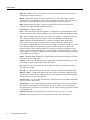
Restrictions
When using the Cisco uBR924 cable access router, keep the following restrictions and limitations in
mind:
•
The Cisco uBR924 is able to implement multiple classes of service (CoS) on the cable interface;
however, separate CoS streams are only available when the cable access router is connected to a
headend that supports multiple CoS per cable access router. In addition, the configuration file
downloaded to the cable access router must specify the use of multiple classes of service.
•
If the Cisco uBR924 cable access router is connected to a DOCSIS 1.0 headend that does not
support multiple CoS per cable access router, voice and data will be mixed, and voice traffic will
be transmitted on a best effort basis. This may cause poorer voice quality and lower data
throughput when calls are being made from the cable access router’s telephone ports. Voice
quality may also be affected when transmitting or downloading large files, or at other times when
network traffic is heavy.
Troubleshooting Tips for the Cisco uBR924 Cable Access Router 1
Related Features and Technologies
Note The Cisco uBR924 cable access router is typically configured at the headend. Most cable
service operators do not permit local configuration at subscriber sites.
Caution Before attempting to reconfigure a Cisco uBR924 cable access router at a subscriber site, contact
your network management, provisioning manager, or billing system administrator to ensure remote
configuration is allowed. If remote configuration is disabled, settings you make and save at the local site will
not remain in effect after the cable access router is reset or powered off and back on. Instead, settings will
return to the previous configuration.
Related Features and Technologies
The Cisco uBR924 cable access router is intended to be used in conjunction with a Cisco uBR7200
series universal broadband router or other DOCSIS-based CMTS located at the cable operator’s
headend facility.
Related Documents
For related information on the Cisco uBR924 cable access router, refer to the following documents:
•
•
•
•
•
•
•
•
•
•
•
•
•
Cisco uBR924 Cable Access Router Quick Start Guide
Cisco uBR924 Cable Access Router Installation and Configuration Guide
Regulatory Compliance and Safety Info. for the Cisco uBR924 Cable Access Router
Cisco uBR7246 Installation and Configuration Guide
Cisco uBR7223 Installation and Configuration Guide
Cisco uBR7200 Series Configuration Notes
Cisco Network Registrar for the uBR7200 Series
Regulatory and Safety Compliance for the Cisco uBR7246
Regulatory and Safety Compliance for the Cisco uBR7223
Cisco uBR7200 Series Features
Cisco uBR7200 Series Feature Enhancements
Cisco uBR7200 Series Feature Enhancements in Release 12.0
Cisco uBR7200 Series Installation and Configuration Guide
Platforms
The Cisco uBR924 cable access router is a single-platform standalone device; it works in
conjunction with the Cisco uBR7200 series universal broadband routers.
2
Cisco IOS Release 12.0(5)T
Related Documents
Prerequisites
In order to use the Cisco uBR924 cable access router for data-over-cable applications, the following
conditions must be met:
•
The Cisco uBR7200 series universal broadband router or other DOCSIS-based CMTS must be
installed at the cable headend and configured. Refer to the Cisco uBR7246 Installation and
Configuration Guide or the Cisco uBR7223 Installation and Configuration Guide for detailed
information.
•
The Cisco uBR924 cable access router must be physically installed and cabled as follows:
— To the headend via CATV coaxial cable
— To at least one PC via the straight-through yellow Ethernet cable supplied with the cable
access router. Refer to the Cisco uBR924 Cable Access Router Quick Start Guide for detailed
information.
•
The PC(s) connected to the Cisco uBR924 cable access router must be configured for Internet
Protocol (IP).
•
The cable service provider must have a correctly configured network DHCP server and
Electronic Industries Association (EIA) downstream channel.
•
Cisco IOS Release 11.3(4)NA or later must be running on the Cisco uBR924 cable access router.
When the cable access router is up and running, you can display the IOS release number by
entering the show version command from user EXEC mode.
Note If the Cisco uBR7246 universal broadband router at the cable headend is using MC16 modem
cards, Cisco IOS Release 11.3(7)NA or later must be running on the Cisco uBR924 cable access
router.
In order to use the Cisco uBR924 cable access router for VoIP-over-cable applications, the following
additional conditions must be met:
•
Cisco IOS Release 12.0(4)XI1 or higher must be running on the Cisco uBR924 cable access
router.
•
In order to run VoIP Fax, the uBR924 cable access router must be configured for voice and you
must be using Cisco IOS Release 12.0(5)T or higher.
•
For multiple CoS (class of service) support, the CMTS must allow the definition of multiple
service identifiers (SIDs) on the upstream. If the CMTS is a Cisco uBR7200 series universal
broadband router, Cisco IOS Release 12.0(4)XI1 or higher must be used on the headend router.
•
The Cisco uBR924 must be configured to operate in routing mode.
Supported MIBs and RFCs
The Cisco uBR924 cable access router supports the following MIBs and RFCs:
•
Cisco Standard MIBs:
— Cisco Product MIB
— Cisco Chassis MIB
— Cisco Syslog MIB
Troubleshooting Tips for the Cisco uBR924 Cable Access Router 3
List of Terms
— Cisco Flash MIB
— Bridge MIB
— IF MIB
— MIB-II
•
Cisco VoIP MIBs:
— Cisco Voice IF MIB
— Cisco Voice Dial-Control MIB
— Cisco Voice Analog IF MIB
— Cisco Dial-Control MIB
•
Radio Frequency Interface Specification—Developed by the Multimedia Cable Network System
(MCNS) consortium. It defines the radio-frequency interface specification for high-speed
data-over-cable systems.
•
CiscoWorks—Network management program for planning, troubleshooting, and monitoring
Cisco internetworks. CiscoWorks uses Simple Network Management Protocol (SNMP) to
monitor all SNMP devices.
— For more information about CiscoWorks on CCO, follow this path:
Products & Ordering: Cisco Products: Network Management: CiscoWorks
— For more information about CiscoWorks on the Documentation CD-ROM, follow this path:
Cisco Product Documentation: Network Management: CiscoWorks
•
Radio Frequency Interface (RFI) MIB—Specific to Data-Over-Cable Service Interface
Specification (DOCSIS) cable implementations. The RIF MIB provides an interface that permits
management of the Cisco uBR924 cable access router over the cable or Ethernet interface. Using
SNMP management applications, this MIB allows access to statistics such as MAC, driver
configuration, and counters.
•
Cable Device MIB—Records statistics related to the configuration and status of the
Cisco uBR924 cable access router. Statistics include an events log and device status. The Cable
Device MIB is very similar to the RFI MIB in that both allow access to statistics; they are
different in that the Cable Device MIB reports statistics on the cable access router, while the RFI
MIB reports statistics on the radio frequency transmissions over the cable television line.
For descriptions of supported MIBs and how to use MIBs, see Cisco’s MIB web site on CCO at
http://www.cisco.com/public/sw-center/netmgmt/cmtk/mibs.shtml.
List of Terms
broadband—Transmission system that combines multiple independent signals onto one cable. In
the cable industry, broadband refers to the frequency-division multiplexing of many signals in a wide
bandwidth of RF frequencies using a hybrid fiber-coaxial (HFC) network.
CATV—Originally stood for Community Antenna Television. Now refers to any coaxial or fiber
cable-based system that provides television services.
cable modem (CM)—A modulator-demodulator device that is placed at subscriber locations to
convey data communications on a cable television system. The Cisco uBR924 cable access router is
also a cable modem.
4
Cisco IOS Release 12.0(5)T
List of Terms
Cable Modem Termination System (CMTS)—A termination system located at the cab le
television system headend or distribution hub which provides complementary functionality to the
cable modems, enabling data connectivity to a wide-are network.
cable router—A modular chassis-based router optimized for data-over-CATV hybrid fiber-coaxial
(HFC) applications.
carrier—A signal on which another, lower-frequency signal is modulated in order to transport the
lower-frequency signal to another location.
Carrier-to-Noise—C/N (also CNR). The difference in amplitude between the desired RF carrier
and the noise in a portion of the spectrum.
channel—A specific frequency allocation and bandwidth. Downstream channels used for television
are 6 MHz wide in the United States; 8 MHz wide in Europe.
CM—cable modem.
CMTS—Cable Modem Termination System.
coaxial cable—The principal physical media over which CATV systems are built.
dB—Decibel. A measure of the relative strength of two signals.
dBm—Decibels with respect to one milliwatt. A unit of RF signal strength used in satellite work and
other communications applications.
dBmV—Decibels with respect to one millivolt in a 75-ohm system. The unit of RF power used in
CATV work in North America.
DHCP—Dynamic Host Configuration Protocol. This protocol provides a mechanism for allocating
IP addresses dynamically so that addresses can be reused when hosts no longer need them.
DOCSIS—Data Over Cable Service Interface Specification. Defines technical specifications for
equipment at both subscriber locations and cable operators’ headends.
downstream—The set of frequencies used to send data from a headend to a subscriber.
FDM—Frequency Division Multiplexing. A data transmission method in which a number of
transmitters share a transmission medium, each occupying a different frequency.
FEC—Forward Error Correction. In data transmission, a process by which additional data is added
that is derived from the payload by an assigned algorithm. It allows the receiver to determine if
certain classes of errors have occurred in transmission and, in some cases, allows other classes of
errors to be corrected.
headend—Central distribution point for a CATV system. Video signals are received here from
satellite (either co-located or remote), frequency converted to the appropriate channels, combined
with locally originated signals, and rebroadcast onto the HFC plant. For a CATV data system, the
headend is the typical place to create a link between the HFC system and any external data networks.
HFC—Hybrid fiber-coaxial (cable network). Older CATV systems were provisioned using only
coaxial cable. Modern systems use fiber transport from the headend to an optical node located in the
neighborhood to reduce system noise. Coaxial cable runs from the node to the subscriber. The fiber
plant is generally a star configuration with all optical node fibers terminating at a headend. The
coaxial cable part of the system is generally a trunk-and-branch configuration.
host—Any end-user computer system that connects to a network. In this document, the term host
refers to the computer system connected to the LAN interface of the cable access router.
ingress noise—Over-the-air signals that are inadvertently coupled into the nominally closed coaxial
cable distribution system. Ingress noise is difficult to track down and intermittent in nature.
Troubleshooting Tips for the Cisco uBR924 Cable Access Router 5
List of Terms
MAC layer—Media Access Control sublayer. Controls access by the cable access router to the
CMTS and to the upstream data slots.
MCNS—Multimedia Cable Network System Partners Ltd. A consortium of cable companies
providing service to the majority of homes in the United States and Canada. This consortium has
decided to drive a standard with the goal of having interoperable cable access routers.
MSO—Multiple System Operator. A cable service provider that operates in more than one
geographic area, thus having multiple headend facilities.
narrowband—A single RF frequency.
NTSC—National Television Systems Committee. A United States TV technical standard, named
after the organization that created the standard in 1941. Specifies a 6 MHz-wide modulated signal.
PAL—Phase Alternating Line. The TV system used in most of Europe, in which the color carrier
phase definition changes in alternate scan lines. Utilizes an 8 MHz-wide modulated signal.
QAM—Quadrature Amplitude Modulation. A method of modulating digital signals onto a
radio-frequency carrier signal in which the value of a symbol consisting of multiple bits is
represented by amplitude and phase states of the carrier. QAM is a modulation scheme mostly used
in the downstream direction (64-QAM, 256-QAM). 16-QAM is expected to be usable in the
upstream direction. Numbers indicate number of code points per symbol. The QAM rate or the
number of points in the QAM constellation can be computed by 2 raised to the power of <number
of bits/symbol>. For example, 16-QAM has 4 bits per symbol, 64-QAM has 6 bits per symbol, and
256-QAM has 8 bits per symbol.
QPSK—Quadrature Phase-Shift Keying. A digital modulation method in which there are 2 data bits
represented with each baud symbol.
ranging—The process of acquiring the correct timing offset such that the transmissions of a cable
access router are aligned with the correct mini-slot boundary.
RF—Radio frequency. The portion of the electromagnetic frequency spectrum from 5 MHz to
approximately 860 MHz.
SECAM—TV system used in France and elsewhere, utilizing an 8 MHz-wide modulated signal.
SID (Service ID)—A number that defines (at the MAC sublayer) a particular mapping between a
cable access router (CM) and the CMTS. The SID is used for the purpose of upstream bandwidth
allocation and class-of-service management.
Signal-to-Noise—S/N (also SNR). The difference in amplitude between a baseband signal and the
noise in a portion of the spectrum.
spectrum reuse—CATV’s most fundamental concept. Historically, the over-the-air spectrum has
been assigned to many purposes other than that of carrying TV signals. This has resulted in an
inadequate supply of spectrum to serve the needs of viewers. Cable can reuse spectrum that is sealed
in its aluminum tubes.
subscriber unit (SU)—An alternate term for cable access router. See cable access router.
upstream—The set of frequencies used to send data from a subscriber to the headend.
6
Cisco IOS Release 12.0(5)T
List of Terms
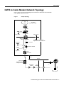
CMTS to Cable Modem Network Topology
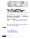
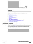
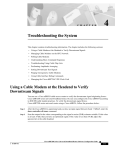
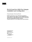
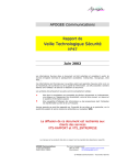
Figure 1 shows the physical relationship between the devices in the HFC network and the
Cisco uBR924 cable access router.
Figure 1
Sample Topology
ISP
WAN
IP-related
ATM, FDDI, 100BT...
100BT
100BT
Proxy server
Cisco
uBR7246
CMTS
Analog TV
100BT
ISP @ home...
100BT
MSD: Maintenance Service
Organization, Cable companies
Upconvertor
DS-RF 54-860 Mhz
Digital TV
Fiber
Transceiver
80 km
1000 ft
Fiber node
(Telephone pole,
underground box)
Top
amplifier
Drop box
13304
Distribution
amplifier
Cisco u BR904
cable modem
Troubleshooting Tips for the Cisco uBR924 Cable Access Router 7
Step 1—Understand How Basic Initialization Works
Troubleshooting Steps
To troubleshoot a malfunctioning cable modem, perform the following tasks:
•
•
•
•
•
Step 1—Understand How Basic Initialization Works
Step 2—Connect to the Cisco uBR924
Step 3—Display the Cisco uBR924’s MAC Log File
Step 4—Interpret the MAC Log File and Take Action
(Optional) Step 5—Use Additional Troubleshooting Commands
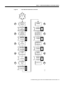
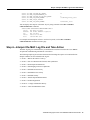
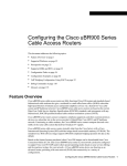
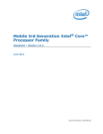
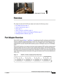
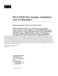
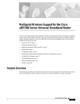
Step 1—Understand How Basic Initialization Works
Before you troubleshoot a Cisco uBR924 cable access router, you should be familiar with the cable
modem initialization process. See Figure 2 and Table 1. Understanding this flowchart and sequence
of events will help you determine where and why connections fail.
The sequence numbers shown in Figure 2 are explained in Table 1, which appears after the
illustration. The Cisco uBR924 will complete all the steps in this flowchart each time it needs to
reestablish ranging and registration with the CMTS.
8
Cisco IOS Release 12.0(5)T
Step 1—Understand How Basic Initialization Works
Figure 2
Cable Modem Initialization Flowchart
Power
on
2
3
4
5
Scan for
downstream
channel
Establish
security
Downstream
sync
established
Security
established
Obtain
upstream
parameters
Transfer
operational
parameters
Upstream
parameter
acquired
Transfer
complete
Start
Ranging
Register with
the Cisco
uBR7246
Ranging and
auto adjust
completed
Registration
complete
Establish
IP
connectivety
Baseline
privacy
initialization
IP
complete
Baseline
privacy
initialized
Establish
time of
day
Operational
6
7
8
9
10
Time of day
established
12960
1
Troubleshooting Tips for the Cisco uBR924 Cable Access Router 9
Step 2—Connect to the Cisco uBR924
.
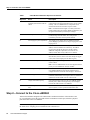
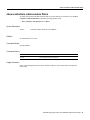
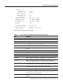
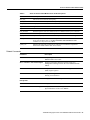
Table 1
Cable Modem Initialization Sequences and Events
Sequence
Event
Description
1
Scan for a downstream channel and
establish synchronization with the
CMTS.
The Cisco uBR924 acquires a downstream channel from the
CMTS and saves the last operational frequency in non-volatile
memory. The Cisco uBR924 tries to reacquire the saved
downstream channel the next time a request is made.
Note An ideal downstream signal is one that synchronizes
QAM symbol timing, FEC framing, MPEG packetization, and
recognizes downstream sync MAC layer messages.
2
Obtain upsteam channel parameters.
The Cisco uBR924 waits for an upstream channel descriptor
(UCD) message from the CMTS. The UCD provides
transmission parameters for the upstream channel.
3
Start ranging for power adjustments.
The ranging process adjusts the Cisco uBR924’s transmit
power. Ranging is performed in two stages: ranging state 1 and
ranging state 2.
4
Establish IP connectivity.
The Cisco uBR924 sends a DHCP request to obtain an IP
address, which is needed for IP connectivity. The DHCP
response also includes the name of a file that contains
additional configuration parameters, the TFTP server’s
address, and the Time of Day (TOD) server’s address.
5
Establish the time of day.
The Cisco uBR924 accesses the TOD server for the current
date and time, which is used to create time stamps for logged
events (such as those displayed in the MAC log file).
6
Establish security.
Keys for privacy are exchanged between the Cisco uBR924
and the CMTS.
Note The Cisco uBR924 cable access router supports baseline
privacy in Cisco IOS Release 12.0(5)T and later.
7
Transfer operational parameters.
After the DHCP and security operations are successful, the
Cisco uBR924 downloads operational parameters from a
configuration file stored on the cable company’s TFTP server.
8
Perform registration.
The Cisco uBR924 registers with the CMTS. After it is
initialized, authenticated, and configured, the Cisco uBR924 is
authorized to forward traffic onto the cable network. .
9
Comply with baseline privacy.
If the software image running on the Cisco uBR924 includes
baseline privacy, link level encryption keys are exchanged
between the CMTS and the Cisco uBR924.
10
Enter the operational maintenance
state.
As soon as the Cisco uBR924 has successfully completed the
above sequence, it enters operational maintenance state.
Step 2—Connect to the Cisco uBR924
Telnet to the IP address assigned to the cable interface or Ethernet interface. If the interface is not
up, you will need to access the Cisco IOS software via the RJ-45 console port, which is a physical
port on the back of the Cisco uBR924.
Note For security purposes, the console port on the Cisco uBR924 may have been deactivated by
the cable service company prior to installation at the subscriber site.
10
Cisco IOS Release 12.0(5)T
Step 3—Display the Cisco uBR924’s MAC Log File
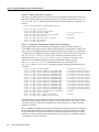
Step 3—Display the Cisco uBR924’s MAC Log File
A MAC-layer circular log file is stored inside the Cisco uBR924. This file contains a history of the
log messages such as state event activities and timestamps. This is the most valuable information for
troubleshooting the cable interface.
The MAC log file is displayed by entering the show controllers cable-modem 0 mac log command
from privileged EXEC mode.
The most useful display fields in this log file are the reported state changes. These fields are preceded
by the message CMAC_LOG_STATE_CHANGE. These fields show how the Cisco uBR924 progresses
through the various processes involved in establishing communication and registration with the
CMTS. The maintenance_state is the normal operational state; the wait_for_link_up_state is
the normal state when the interface is shut down.
Note Because the MAC log file only holds a snapshot of 1023 entries at a time, you should try to
display the Cisco uBR924’s log file within 5 minutes after the reset or problem occurs.
The following is the normal progression of states as displayed by the MAC log:
wait_for_link_up_state
ds_channel_scanning_state
wait_ucd_state
wait_map_state
ranging_1_state
ranging_2_state
dhcp_state
establish_tod_state
security_association_state
configuration_file_state
registration_state
establish_privacy_state
maintenance_state
Note To translate this output into more meaningful information, see “Step 4—Interpret the MAC
Log File and Take Action” on page 13.
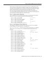
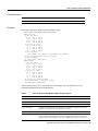
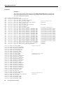
Following is an example of what the MAC log file looks like when the Cisco uBR924 interface
successfully comes up and registers with the CMTS. The output you see is directly related to the
messages that are exchanged between the Cisco uBR924 and the headend CMTS.
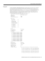
uBR924# show controllers cable-modem 0 mac log
508144.340 CMAC_LOG_DRIVER_INIT_IDB_RESET
508144.342 CMAC_LOG_LINK_DOWN
508144.344 CMAC_LOG_LINK_UP
508144.348 CMAC_LOG_STATE_CHANGE
508144.350 CMAC_LOG_WILL_SEARCH_DS_FREQUENCY_BAND
508144.354 CMAC_LOG_WILL_SEARCH_DS_FREQUENCY_BAND
508144.356 CMAC_LOG_WILL_SEARCH_DS_FREQUENCY_BAND
508144.360 CMAC_LOG_WILL_SEARCH_DS_FREQUENCY_BAND
508144.362 CMAC_LOG_WILL_SEARCH_DS_FREQUENCY_BAND
508144.366 CMAC_LOG_WILL_SEARCH_DS_FREQUENCY_BAND
508144.370 CMAC_LOG_WILL_SEARCH_DS_FREQUENCY_BAND
508144.372 CMAC_LOG_WILL_SEARCH_DS_FREQUENCY_BAND
508144.376 CMAC_LOG_WILL_SEARCH_DS_FREQUENCY_BAND
508144.380 CMAC_LOG_WILL_SEARCH_DS_FREQUENCY_BAND
508144.382 CMAC_LOG_WILL_SEARCH_DS_FREQUENCY_BAND
508144.386 CMAC_LOG_WILL_SEARCH_DS_FREQUENCY_BAND
0x08098FEA
ds_channel_scanning_state
88/453000000/855000000/6000000
89/93000000/105000000/6000000
90/111250000/117250000/6000000
91/231012500/327012500/6000000
92/333015000/333015000/6000000
93/339012500/399012500/6000000
94/405000000/447000000/6000000
95/123015000/129015000/6000000
96/135012500/135012500/6000000
97/141000000/171000000/6000000
98/219000000/225000000/6000000
99/177000000/213000000/6000000
Troubleshooting Tips for the Cisco uBR924 Cable Access Router 11
Step 3—Display the Cisco uBR924’s MAC Log File
508144.390
508145.540
508146.120
508146.122
508146.124
508147.554
508147.558
508147.558
508147.622
508147.624
508148.058
508148.060
508148.062
508148.064
508148.066
508148.068
508148.070
508148.072
508148.562
508148.566
508148.568
508148.570
508148.572
508148.574
508148.576
508148.578
508148.580
508155.820
508155.824
508155.826
508155.826
508155.828
508165.892
508165.894
508165.896
508165.898
508165.900
508175.962
508175.964
508175.966
508175.968
508176.982
508176.984
508176.986
508176.988
508176.988
508176.990
508176.992
508176.996
508177.120
508177.126
508177.154
508177.158
508177.160
508177.162
508177.164
508177.166
508178.280
508178.300
508178.302
508178.306
508178.310
508178.312
508178.314
508178.316
12
Cisco IOS Release 12.0(5)T
CMAC_LOG_WILL_SEARCH_SAVED_DS_FREQUENCY
CMAC_LOG_UCD_MSG_RCVD
CMAC_LOG_DS_64QAM_LOCK_ACQUIRED
CMAC_LOG_DS_CHANNEL_SCAN_COMPLETED
CMAC_LOG_STATE_CHANGE
CMAC_LOG_UCD_MSG_RCVD
CMAC_LOG_UCD_NEW_US_FREQUENCY
CMAC_LOG_SLOT_SIZE_CHANGED
CMAC_LOG_FOUND_US_CHANNEL
CMAC_LOG_STATE_CHANGE
CMAC_LOG_MAP_MSG_RCVD
CMAC_LOG_INITIAL_RANGING_MINISLOTS
CMAC_LOG_STATE_CHANGE
CMAC_LOG_RANGING_OFFSET_SET_TO
CMAC_LOG_POWER_LEVEL_IS
CMAC_LOG_STARTING_RANGING
CMAC_LOG_RANGING_BACKOFF_SET
CMAC_LOG_RNG_REQ_QUEUED
CMAC_LOG_RNG_REQ_TRANSMITTED
CMAC_LOG_RNG_RSP_MSG_RCVD
CMAC_LOG_RNG_RSP_SID_ASSIGNED
CMAC_LOG_ADJUST_RANGING_OFFSET
CMAC_LOG_RANGING_OFFSET_SET_TO
CMAC_LOG_ADJUST_TX_POWER
CMAC_LOG_POWER_LEVEL_IS
CMAC_LOG_STATE_CHANGE
CMAC_LOG_RNG_REQ_QUEUED
CMAC_LOG_RNG_REQ_TRANSMITTED
CMAC_LOG_RNG_RSP_MSG_RCVD
CMAC_LOG_ADJUST_RANGING_OFFSET
CMAC_LOG_RANGING_OFFSET_SET_TO
CMAC_LOG_RANGING_CONTINUE
CMAC_LOG_RNG_REQ_TRANSMITTED
CMAC_LOG_RNG_RSP_MSG_RCVD
CMAC_LOG_ADJUST_TX_POWER
CMAC_LOG_POWER_LEVEL_IS
CMAC_LOG_RANGING_CONTINUE
CMAC_LOG_RNG_REQ_TRANSMITTED
CMAC_LOG_RNG_RSP_MSG_RCVD
CMAC_LOG_RANGING_SUCCESS
CMAC_LOG_STATE_CHANGE
CMAC_LOG_DHCP_ASSIGNED_IP_ADDRESS
CMAC_LOG_DHCP_TFTP_SERVER_ADDRESS
CMAC_LOG_DHCP_TOD_SERVER_ADDRESS
CMAC_LOG_DHCP_SET_GATEWAY_ADDRESS
CMAC_LOG_DHCP_TZ_OFFSET
CMAC_LOG_DHCP_CONFIG_FILE_NAME
CMAC_LOG_DHCP_ERROR_ACQUIRING_SEC_SVR_ADDR
CMAC_LOG_DHCP_COMPLETE
CMAC_LOG_STATE_CHANGE
CMAC_LOG_TOD_REQUEST_SENT
CMAC_LOG_TOD_REPLY_RECEIVED
CMAC_LOG_TOD_COMPLETE
CMAC_LOG_STATE_CHANGE
CMAC_LOG_SECURITY_BYPASSED
CMAC_LOG_STATE_CHANGE
CMAC_LOG_LOADING_CONFIG_FILE
CMAC_LOG_CONFIG_FILE_PROCESS_COMPLETE
CMAC_LOG_STATE_CHANGE
CMAC_LOG_REG_REQ_MSG_QUEUED
CMAC_LOG_REG_REQ_TRANSMITTED
CMAC_LOG_REG_RSP_MSG_RCVD
CMAC_LOG_COS_ASSIGNED_SID
CMAC_LOG_COS_ASSIGNED_SID
CMAC_LOG_COS_ASSIGNED_SID
699000000
3
699000000
wait_ucd_state
3
20000000
8
1
wait_map_state
40
ranging_1_state
9610
28.0 dBmV (commanded)
0
0
2
2408
12018
20
33.0 dBmV (commanded)
ranging_2_state
2
-64
11954
-9
31.0
dBmV (commanded)
dhcp_state
188.188.1.62
4.0.0.1
4.0.0.32
360
platinum.cm
establish_tod_state
3107617539
security_association_state
configuration_file_state
platinum.cm
registration_state
5/19
6/20
7/21
Step 4—Interpret the MAC Log File and Take Action
508178.318
508178.320
508178.322
508178.324
508178.326
508178.328
CMAC_LOG_RNG_REQ_QUEUED
CMAC_LOG_REGISTRATION_OK
CMAC_LOG_REG_RSP_ACK_MSG_QUEUED
CMAC_LOG_STATE_CHANGE
CMAC_LOG_NO_PRIVACY
CMAC_LOG_STATE_CHANGE
19
0
establish_privacy_state
maintenance_state
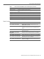
You can display other aspects of the MAC layer by using variations of the show controllers
cable-modem 0 mac command:
uBR924# show controllers cable-modem 0 mac ?
errors
Mac Error Log data
hardware All CM Mac Hardware registers
log
Mac log data
resets
Resets of the MAC
state
Current MAC state
For examples and descriptions of how to use these keywords, see the show controllers
cable-modem mac command reference page.
Step 4—Interpret the MAC Log File and Take Action
The MAC log file gives a detailed history of initialization events that occurred in the Cisco uBR924.
All pertinent troubleshooting information is stored here.
The following sample log file is broken down into the chronological sequence of events listed below.
Sample comments are also included in the log file.
•
•
•
•
•
•
•
•
•
•
•
Event 1—Wait for the Link to Come Up
Event 2—Scan for a Downstream Channel, then Synchronize
Event 3—Obtain Upstream Parameters
Event 4—Start Ranging for Power Adjustments
Event 5—Establish IP Connectivity
Event 6—Establish the Time of Day
Event 7—Establish Security
Event 8—Transfer Operational Parameters
Event 9—Perform Registration
Event 10—Comply with Baseline Privacy
Event 11—Enter the Maintenance State
Troubleshooting Tips for the Cisco uBR924 Cable Access Router 13
Step 4—Interpret the MAC Log File and Take Action
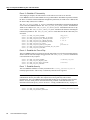
Event 1—Wait for the Link to Come Up
When the Cisco uBR924 cable access router is powered on and begins initialization, the first event
that occurs is that the MAC layer informs the cable access router drivers that it needs to reset. The
LINK_DOWN and LINK_UP fields are similar to the shut and no shut conditions on a standard Cisco
interface.
uBR924# show controllers cable-modem 0 mac log
528302.040
528302.042
528302.044
528302.046
528302.048
528308.428
528308.432
528308.434
CMAC_LOG_LINK_DOWN
CMAC_LOG_RESET_FROM_DRIVER
CMAC_LOG_STATE_CHANGE
CMAC_LOG_DRIVER_INIT_IDB_SHUTDOWN
CMAC_LOG_LINK_DOWN
CMAC_LOG_DRIVER_INIT_IDB_RESET
CMAC_LOG_LINK_DOWN
CMAC_LOG_LINK_UP
wait_for_link_up_state
0x08098D02
0x08098E5E
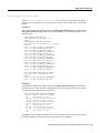
Event 2—Scan for a Downstream Channel, then Synchronize
Different geographical regions and different cable plants use different frequency bands. The
Cisco uBR924 cable access router uses a built-in default frequency scanning feature to address this
issue. After the Cisco uBR924 finds a successful downstream frequency channel, it saves the channel
to NVRAM. The Cisco uBR924 recalls this value the next time it needs to synchronize its frequency.
The CMAC_LOG_WILL_SEARCH_DS_FREQUENCY_BAND field tells you what frequency the Cisco
uBR924 will scan for. The CMAC_LOG_WILL_SEARCH_SAVED_DS_FREQUENCY field tells you the
frequency the Cisco uBR924 locked onto and saved to NVRAM for future recall. The
CMAC_LOG_DS_64QAM_LOCK_ACQUIRED field communicates the same information. The
CMAC_LOG_DS_CHANNEL_SCAN_COMPLETED field indicates that the scanning and synchronization was
successful.
508144.348
508144.350
508144.354
508144.356
508144.360
508144.362
508144.366
508144.370
508144.372
508144.376
508144.380
508144.382
508144.386
508144.390
508145.540
508146.120
508146.122
CMAC_LOG_STATE_CHANGE
CMAC_LOG_WILL_SEARCH_DS_FREQUENCY_BAND
CMAC_LOG_WILL_SEARCH_DS_FREQUENCY_BAND
CMAC_LOG_WILL_SEARCH_DS_FREQUENCY_BAND
CMAC_LOG_WILL_SEARCH_DS_FREQUENCY_BAND
CMAC_LOG_WILL_SEARCH_DS_FREQUENCY_BAND
CMAC_LOG_WILL_SEARCH_DS_FREQUENCY_BAND
CMAC_LOG_WILL_SEARCH_DS_FREQUENCY_BAND
CMAC_LOG_WILL_SEARCH_DS_FREQUENCY_BAND
CMAC_LOG_WILL_SEARCH_DS_FREQUENCY_BAND
CMAC_LOG_WILL_SEARCH_DS_FREQUENCY_BAND
CMAC_LOG_WILL_SEARCH_DS_FREQUENCY_BAND
CMAC_LOG_WILL_SEARCH_DS_FREQUENCY_BAND
CMAC_LOG_WILL_SEARCH_SAVED_DS_FREQUENCY
CMAC_LOG_UCD_MSG_RCVD
CMAC_LOG_DS_64QAM_LOCK_ACQUIRED
CMAC_LOG_DS_CHANNEL_SCAN_COMPLETED
ds_channel_scanning_state
88/453000000/855000000/6000000
89/93000000/105000000/6000000
90/111250000/117250000/6000000
91/231012500/327012500/6000000
92/333015000/333015000/6000000
93/339012500/399012500/6000000
94/405000000/447000000/6000000
95/123015000/129015000/6000000
96/135012500/135012500/6000000
97/141000000/171000000/6000000
98/219000000/225000000/6000000
99/177000000/213000000/6000000
699000000
3
699000000
A frequency band is a group of adjacent channels. These bands are numbered from 88 to 99. Each
band has starting and ending digital carrier frequencies and a 6 MHz step size. For example, a search
of EIA channels 95-97 is specified using band 89. The starting frequency is 93 MHz, the ending
frequency is 105 MHz.
The Cisco uBR924’s default frequency bands correspond to the North American EIA CATV channel
plan for 6 MHz channel slots between 90 MHz and 858 MHz. For example, EIA channel 95 occupies
the slot 90-96 MHz. The digital carrier frequency is specified as the center frequency of 93 MHz.
Channel 95 is usually specified using the analog video carrier frequency of 91.25 MHz, which lies
1.75 MHz below the center of the slot.
14
Cisco IOS Release 12.0(5)T
Step 4—Interpret the MAC Log File and Take Action
The search table is arranged so that the first frequencies tried are above 450 MHz. Because many
CATV systems have been upgraded from 450 MHz to 750 MHz coaxial cable, digital channels have
a high chance of being assigned in the new spectrum. The search table omits channels below 90 MHz
and above 860 MHz since the DOCSIS specification does not mandate their coverage.
Some CATV systems use alternative frequency plans such as the IRC (Incrementally Related
Carrier) plan and HRC (Harmonically Related Carrier) plan. Cisco cable access routers support both
of these plans. Most of the IRC channel slots overlap the EIA plan.
Event 3—Obtain Upstream Parameters
The Cisco uBR924 waits for an upstream channel descriptor (UCD) message from the headend
CMTS. The UCD provides transmission parameters for the upstream channel.
508146.124
508147.554
508147.558
508147.558
508147.622
508147.624
508148.058
508148.060
CMAC_LOG_STATE_CHANGE
CMAC_LOG_UCD_MSG_RCVD
CMAC_LOG_UCD_NEW_US_FREQUENCY
CMAC_LOG_SLOT_SIZE_CHANGED
CMAC_LOG_FOUND_US_CHANNEL
CMAC_LOG_STATE_CHANGE
CMAC_LOG_MAP_MSG_RCVD
CMAC_LOG_INITIAL_RANGING_MINISLOTS
wait_ucd_state
3
20000000
8
1
wait_map_state
40
Event 4—Start Ranging for Power Adjustments
The ranging process adjusts the transmit power of the cable access router. The Cisco uBR924
performs ranging in two stages: ranging state 1 and ranging state 2.
The CMAC_LOG_POWER_LEVEL_IS field is the power level that the CMTS told the Cisco uBR924 to
adjust to. The CMAC_LOG_RANGING_SUCCESS field indicates that the ranging adjustment was
successful.
508148.062
508148.064
508148.066
508148.068
508148.070
508148.072
508148.562
508148.566
508148.568
508148.570
508148.572
508148.574
508148.576
508148.578
508148.580
508155.820
508155.824
508155.826
508155.826
508155.828
508165.892
508165.894
508165.896
508165.898
508165.900
508175.962
508175.964
508175.966
CMAC_LOG_STATE_CHANGE
CMAC_LOG_RANGING_OFFSET_SET_TO
CMAC_LOG_POWER_LEVEL_IS
CMAC_LOG_STARTING_RANGING
CMAC_LOG_RANGING_BACKOFF_SET
CMAC_LOG_RNG_REQ_QUEUED
CMAC_LOG_RNG_REQ_TRANSMITTED
CMAC_LOG_RNG_RSP_MSG_RCVD
CMAC_LOG_RNG_RSP_SID_ASSIGNED
CMAC_LOG_ADJUST_RANGING_OFFSET
CMAC_LOG_RANGING_OFFSET_SET_TO
CMAC_LOG_ADJUST_TX_POWER
CMAC_LOG_POWER_LEVEL_IS
CMAC_LOG_STATE_CHANGE
CMAC_LOG_RNG_REQ_QUEUED
CMAC_LOG_RNG_REQ_TRANSMITTED
CMAC_LOG_RNG_RSP_MSG_RCVD
CMAC_LOG_ADJUST_RANGING_OFFSET
CMAC_LOG_RANGING_OFFSET_SET_TO
CMAC_LOG_RANGING_CONTINUE
CMAC_LOG_RNG_REQ_TRANSMITTED
CMAC_LOG_RNG_RSP_MSG_RCVD
CMAC_LOG_ADJUST_TX_POWER
CMAC_LOG_POWER_LEVEL_IS
CMAC_LOG_RANGING_CONTINUE
CMAC_LOG_RNG_REQ_TRANSMITTED
CMAC_LOG_RNG_RSP_MSG_RCVD
CMAC_LOG_RANGING_SUCCESS
ranging_1_state
9610
28.0 dBmV (commanded)
0
0
2
2408
12018
20
33.0 dBmV (commanded)
ranging_2_state
2
-64
11954
-9
31.0
dBmV (commanded)
Troubleshooting Tips for the Cisco uBR924 Cable Access Router 15
Step 4—Interpret the MAC Log File and Take Action
Event 5—Establish IP Connectivity
After ranging is complete, the cable interface on the cable access router is UP. Now the
Cisco uBR924 accesses a remote DHCP server to get an IP address. The DHCP request also includes
the name of a file that contains additional configuration parameters, the TFTP server’s address and
the Time of Day (TOD) server’s address.
The CMAC_LOG_DHCP_ASSIGNED_IP_ADDRESS field indicates the IP address assigned from the DHCP
server to the Cisco uBR924 interface. The CMAC_LOG_DHCP_TFTP_SERVER_ADDRESS field marks the
TFTP server’s address. The CMAC_LOG_DHCP_TOD_SERVER_ADDRESS field indicates the time of day
server’s address. The CMAC_LOG_DHCP_CONFIG_FILE_NAME field shows the filename containing the
transmission parameters. The CMAC_LOG_DHCP_COMPLETE field shows that the IP connectivity was
successful.
508175.968
508176.982
508176.984
508176.986
508176.988
508176.988
508176.990
508176.992
508176.996
CMAC_LOG_STATE_CHANGE
CMAC_LOG_DHCP_ASSIGNED_IP_ADDRESS
CMAC_LOG_DHCP_TFTP_SERVER_ADDRESS
CMAC_LOG_DHCP_TOD_SERVER_ADDRESS
CMAC_LOG_DHCP_SET_GATEWAY_ADDRESS
CMAC_LOG_DHCP_TZ_OFFSET
CMAC_LOG_DHCP_CONFIG_FILE_NAME
CMAC_LOG_DHCP_ERROR_ACQUIRING_SEC_SVR_ADDR
CMAC_LOG_DHCP_COMPLETE
dhcp_state
188.188.1.62
4.0.0.1
4.0.0.32
360
platinum.cm
Event 6—Establish the Time of Day
The Cisco uBR924 cable access router accesses the Time of Day server for the current date and time,
which is used to create time stamps for logged events. The CMAC_LOG_TOD_COMPLETE field indicates
a successful time of day sequence.
508177.120
508177.126
508177.154
508177.158
CMAC_LOG_STATE_CHANGE
CMAC_LOG_TOD_REQUEST_SENT
CMAC_LOG_TOD_REPLY_RECEIVED
CMAC_LOG_TOD_COMPLETE
establish_tod_state
3107617539
Event 7—Establish Security
The Cisco uBR924 establishes a security association. The security_association_state is
normally bypassed since “full security” as defined by DOCSIS is not supported.
Note “Full security” was a request made by MSOs for a very strong authorization and
authentication check by the CMTS. This request has not been granted by cable modem
manufacturers. The Cisco uBR924 supports DOCSIS baseline privacy beginning with Cisco IOS
Release 12.0(5)T, which protects user’s data from being “sniffed” on the cable network. For
information on baseline privacy, refer to “Event 10—Comply with Baseline Privacy” on page 17.
508177.160 CMAC_LOG_STATE_CHANGE
508177.162 CMAC_LOG_SECURITY_BYPASSED
16
Cisco IOS Release 12.0(5)T
security_association_state
Step 4—Interpret the MAC Log File and Take Action
Event 8—Transfer Operational Parameters
After the DHCP and security operations are successful, the Cisco uBR924 downloads operational
parameters via a configuration file located on the cable company’s TFTP server. The
CMAC_LOG_DHCP_CONFIG_FILE_NAME field shows the filename containing the transmission
parameters.
508177.164 CMAC_LOG_STATE_CHANGE
508177.166 CMAC_LOG_LOADING_CONFIG_FILE
508178.280 CMAC_LOG_CONFIG_FILE_PROCESS_COMPLETE
configuration_file_state
platinum.cm
Event 9—Perform Registration
After the Cisco uBR924 is initialized, authenticated, and configured, it requests to be registered with
the headend CMTS. The CMAC_LOG_COS_ASSIGNED_SID field assigns a class of service (CoS)
number and a service ID (SID). Multiple CoS entries in the configuration file imply that multiple
SIDs are supported by the cable access router. If several cable access routers use the same
configuration file, they will have the same CoS numbers but will be assigned different SIDs.
A successful registration is indicated by the CMAC_LOG_REGISTRATION_OK field.
508178.300
508178.302
508178.306
508178.310
508178.312
508178.314
508178.316
508178.318
508178.320
CMAC_LOG_STATE_CHANGE
CMAC_LOG_REG_REQ_MSG_QUEUED
CMAC_LOG_REG_REQ_TRANSMITTED
CMAC_LOG_REG_RSP_MSG_RCVD
CMAC_LOG_COS_ASSIGNED_SID
CMAC_LOG_COS_ASSIGNED_SID
CMAC_LOG_COS_ASSIGNED_SID
CMAC_LOG_RNG_REQ_QUEUED
CMAC_LOG_REGISTRATION_OK
registration_state
5/19
6/20
7/21
19
Event 10—Comply with Baseline Privacy
Keys for baseline privacy are exchanged between the Cisco uBR924 and the headend CMTS. During
this event, a link level encryption is performed so that a user’s data cannot be “sniffed” by anyone
else who is on the cable network.
Following is a trace that shows baseline privacy enabled. The key management protocol is
responsible for exchanging two types of keys: KEKs and TEKs. The KEK (key exchange key, also
referred to as the authorization key) is used by the headend CMTS to encrypt the TEKs (traffic
encryption keys) it sends to the Cisco uBR924. The TEKs are used to encrypt/decrypt the data. There
is a TEK for each SID that is configured to use privacy.
851.088 CMAC_LOG_STATE_CHANGE
establish_privacy_state
851.094 CMAC_LOG_PRIVACY_FSM_STATE_CHANGE
machine: KEK, event/state:
EVENT_1_PROVISIONED/STATE_A_START, new state: STATE_B_AUTH_WAIT
851.102 CMAC_LOG_BPKM_REQ_TRANSMITTED
851.116 CMAC_LOG_BPKM_RSP_MSG_RCVD
851.120 CMAC_LOG_PRIVACY_FSM_STATE_CHANGE
machine: KEK, event/state:
EVENT_3_AUTH_REPLY/STATE_B_AUTH_WAIT, new state: STATE_C_AUTHORIZED
856.208 CMAC_LOG_PRIVACY_FSM_STATE_CHANGE
machine: TEK, event/state:
EVENT_2_AUTHORIZED/STATE_A_START, new state: STATE_B_OP_WAIT
856.220 CMAC_LOG_BPKM_REQ_TRANSMITTED
856.224 CMAC_LOG_BPKM_RSP_MSG_RCVD
856.230 CMAC_LOG_PRIVACY_FSM_STATE_CHANGE
machine: TEK, event/state:
EVENT_8_KEY_REPLY/STATE_B_OP_WAIT, new state: STATE_D_OPERATIONAL
856.326 CMAC_LOG_PRIVACY_INSTALLED_KEY_FOR_SID
2
856.330 CMAC_LOG_PRIVACY_ESTABLISHED
Note In order for baseline privacy to work, you must use a code image name on the Cisco uBR924
that contains the characters k1. In addition, baseline privacy must be supported on the headend
CMTS, and it must be turned on in the configuration file that is downloaded to the Cisco uBR924.
Troubleshooting Tips for the Cisco uBR924 Cable Access Router 17
Step 5—Use Additional Troubleshooting Commands
Event 11—Enter the Maintenance State
As soon as the Cisco uBR924 has successfully completed the above events, it enters the operational
maintenance state and is authorized to forward traffic into the cable network.
508178.322 CMAC_LOG_STATE_CHANGE
maintenance_state
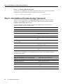
Step 5—Use Additional Troubleshooting Commands
You can use other show controllers and debug cable modem commands to troubleshoot different
aspects of a Cisco uBR924 cable access router. However, the most useful command is the show
controllers cable-modem 0 mac command.
To display additional controller information inside a Cisco uBR924, enter one or more of the
following commands in privileged EXEC mode:
Command
Purpose
show controllers cable-modem
Displays high-level controller information.
show controllers cable-modem bpkm
Displays privacy state information.
show controllers cable-modem des
Displays information about the Data Encryption
Standard (DES) engine registers.
show controllers cable-modem filters
Displays information about the MAC and SID filters.
show controllers cable-modem lookup-table
Displays the Cisco uBR924’s internal mini-slot lookup
table.
show controllers cable-modem mac [errors | hardware |
log | resets | state]
Displays detailed MAC-layer information.
show controllers cable-modem phy
Displays physical-layer information such as receive and
transmit physical registers.
show controllers cable-modem tuner
Displays tuning information.
show interface cable-modem
Displays information about the Cisco uBR924
interface.
To debug different components of a Cisco uBR924, enter one or more of the following commands
in privileged EXEC mode:
18
Command
Purpose
debug cable-modem bpkm {errors | events | packets}
Debugs baseline privacy information.
debug cable-modem bridge
Debugs the bridge filter.
debug cable-modem error
Debugs cable interface errors.
debug cable-modem interrupts
Debugs Cisco uBR924 interface interrupts.
debug cable-modem mac {log [verbose] | messages}
Displays and debugs the MAC-layer log entries in
real time.
debug cable-modem map
Debugs map message processing information.
Cisco IOS Release 12.0(5)T
Step 5—Use Additional Troubleshooting Commands
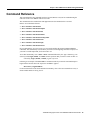
Command Reference
This section describes the commands used in Cisco IOS Release 12.0(5)T for troubleshooting the
cable side of the Cisco uBR924 cable access router.
The commands used to troubleshoot VoIP applications are documented in the Cisco IOS
Release 12.0 command references.
•
•
•
•
•
•
•
•
show controllers cable-modem
show controllers cable-modem bpkm
show controllers cable-modem des
show controllers cable-modem filters
show controllers cable-modem lookup-table
show controllers cable-modem mac
show controllers cable-modem phy
show controllers cable-modem tuner
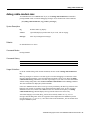
In Cisco IOS Release 12.0(1)T or later, you can search and filter the output for show and more
commands. This functionality is useful when you need to sort through large amounts of output, or if
you want to exclude output that you do not need to see.
To use this functionality, enter a show or more command followed by the “pipe” character (|), one
of the keywords begin, include, or exclude, and an expression that you want to search or filter on:
command | {begin | include | exclude} regular-expression
Following is an example of the show atm vc command in which you want the command output to
begin with the first line where the expression “PeakRate” appears:
show atm vc | begin PeakRate
For more information on the search and filter functionality, refer to the Cisco IOS Release 12.0(1)T
feature module titled CLI String Search.
Troubleshooting Tips for the Cisco uBR924 Cable Access Router 19
show controllers cable-modem
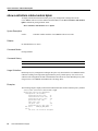
show controllers cable-modem
To display high-level controller information about a Cisco uBR924 cable access router, use the show
controllers cable-modem command in privileged EXEC mode.
show controllers cable-modem number
Syntax Description
number
Controller number inside the Cisco uBR924.
Defaults
No default behavior or values.
Command Modes
Privileged EXEC
Command History
Release
Modification
11.3 NA
This command was first introduced.
Usage Guidelines
The show controllers cable-modem display begins with information from the first few registers of
the Broadcom BCM3300 chip. Next is buffer information for the receive, receive MAC message,
buffer descriptor, and packet descriptor rings. Then comes MIB statistics from the BCM3300 chip,
DMA base registers to indicate where the rings start, global control and status information, and
finally interrupts for the interrupt code.
When using this command, be sure to check the tx_count and the tx_head and tx_tail values for the
buffer descriptor (TX BD) and packet descriptor (TX PD) rings. The tx_count should be greater than
0, and the tx_head and tx_tail values should not be equal. If these values do not change for a long
period of time, it indicates there are packets stuck on the ring. This condition is often caused by the
headend not giving grants.
20
Cisco IOS Release 12.0(5)T
show controllers cable-modem
Examples
Following is sample output for the show controllers cable-modem 0 command:
uBR924# show controllers cable-modem 0
BCM Cable interface 0:
BCM3300 unit 0, idb 0x200EB4, ds 0x82D4748, regaddr = 0x800000, reset_mask 0x80
station address 0010.7b43.aa01 default station address 0010.7b43.aa01
PLD VERSION: 32
MAC State is ranging_2_state, Prev States = 7
MAC mcfilter 01E02F00 data mcfilter 01000000
DS: BCM 3116 Receiver: Chip id = 2
US: BCM 3037 Transmitter: Chip id = 30B4
Tuner: status=0x00
Rx: tuner_freq 699000000, symbol_rate 5055849, local_freq 11520000
snr_estimate 33406, ber_estimate 0, lock_threshold 26000
QAM in lock, FEC in lock, qam_mode QAM_64
Tx: tx_freq 20000000, power_level 0x3E, symbol_rate 1280000
DHCP: TFTP server = 4.0.0.32, TOD server = 4.0.0.188
Security server = 0.0.0.0, Timezone Offest = 0.0.4.32
Config filename =
buffer size 1600
RX data PDU ring with 32 entries at 0x201D40
rx_head = 0x201D78 (7), rx_p = 0x831BE04 (7)
00 pak=0x8326318 buf=0x225626 status=0x80 pak_size=0
01 pak=0x83241A0 buf=0x21DE5A status=0x80 pak_size=0
02 pak=0x83239C0 buf=0x21C22A status=0x80 pak_size=0
03 pak=0x8328C70 buf=0x22EA22 status=0x80 pak_size=0
04 pak=0x8325F28 buf=0x22480E status=0x80 pak_size=0
05 pak=0x8327CB0 buf=0x22B1C2 status=0x80 pak_size=0
06 pak=0x8323BB8 buf=0x21C936 status=0x80 pak_size=0
RX MAC message ring with 8 entries at 0x201E80
rx_head_mac = 0x201E88 (1), rx_p_mac = 0x831BE80 (1)
00 pak=0x8326120 buf=0x224F1A status=0x80 pak_size=0
01 pak=0x8324590 buf=0x21EC72 status=0x80 pak_size=0
02 pak=0x8323FA8 buf=0x21D74E status=0x80 pak_size=0
03 pak=0x8326EE8 buf=0x22806E status=0x80 pak_size=0
04 pak=0x8328E68 buf=0x22F12E status=0x80 pak_size=0
05 pak=0x8327AB8 buf=0x22AAB6 status=0x80 pak_size=0
06 pak=0x8328880 buf=0x22DC0A status=0x80 pak_size=0
07 pak=0x8326CF0 buf=0x227962 status=0xA0 pak_size=0
TX BD ring with 8 entries at 0x201FB8, tx_count = 0
tx_head = 0x201FD8 (4), head_txp = 0x831BF20 (4)
tx_tail = 0x201FD8 (4), tail_txp = 0x831BF20 (4)
00 pak=0x000000 buf=0x200000 status=0x00 pak_size=0
01 pak=0x000000 buf=0x200000 status=0x00 pak_size=0
02 pak=0x000000 buf=0x200000 status=0x00 pak_size=0
03 pak=0x000000 buf=0x200000 status=0x00 pak_size=0
04 pak=0x000000 buf=0x200000 status=0x00 pak_size=0
05 pak=0x000000 buf=0x200000 status=0x00 pak_size=0
06 pak=0x000000 buf=0x200000 status=0x00 pak_size=0
07 pak=0x000000 buf=0x200000 status=0x20 pak_size=0
TX PD ring with 8 entries at 0x202038, tx_count = 0
tx_head_pd = 0x202838 (4)
tx_tail_pd = 0x202838 (4)
00 status=0x00 bd_index=0x0000 len=0x0000 hdr_len=0x0000
Troubleshooting Tips for the Cisco uBR924 Cable Access Router 21
show controllers cable-modem
ehdr: 01 06 02
01 status=0x00
ehdr: 01 06 02
02 status=0x00
ehdr: 01 06 02
03 status=0x00
ehdr: 01 06 02
04 status=0x00
ehdr: 01 06 02
05 status=0x00
ehdr: 01 06 02
06 status=0x00
ehdr: 01 06 02
07 status=0x20
ehdr: 01 06 02
74 34 11
bd_index=0x0001
74 34 11
bd_index=0x0002
74 34 11
bd_index=0x0003
74 34 11
bd_index=0x0004
74 34 11
bd_index=0x0005
74 34 11
bd_index=0x0006
74 34 11
bd_index=0x0007
74 34 11
len=0x0000 hdr_len=0x0000
len=0x0000 hdr_len=0x0000
len=0x0000 hdr_len=0x0000
len=0x0000 hdr_len=0x0000
len=0x0000 hdr_len=0x0000
len=0x0000 hdr_len=0x0000
len=0x0000 hdr_len=0x0000
MIB Statistics
DS fifo full = 0, Rerequests = 0
DS mac msg overruns = 0, DS data overruns = 0
Qualified maps = 348, Qualified syncs = 73
CRC fails = 0, HDR chk fails = 0
Data pdus = 0, Mac msgs = 423
Valid hdrs = 423
BCM3300 Registers:
downstream dma:
ds_data_bd_base=0x001D40, ds_mac_bd_base=0x001E80
ds_data_dma_ctrl=0x98, ds_mac_dma_ctrl=0xD8
ds_dma_data_index=0x0007, ds_dma_msg_index=0x0000
upstream dma:
us_bd_base=0x001FB8, us_pd_base=0x002038
us_dma_ctrl=0x80, us_dma_tx_start=0x00
Global control and status:
global_ctrl_status=0x00
interrupts:
irq_pend=0x0008, irq_mask=0x00F7
Table 2 briefly describes some of the fields shown in the display. For more information, see the
Broadcom documentation for the BCM3300 chip.
Table 2
22
Show Controllers Cable-Modem Field Descriptions
Field
Description
BCM3300 unit
The unit number of this BCM3300 chip.
idb
Interface description block number.
ds
Downstream channel.
regaddr
Indicates the start of the BCM3300 registers.
reset_mask
Indicates the bit to hit when resetting the chip.
station address
MAC address of this Cisco uBR924 cable access router interface.
default station address
Default MAC address assigned by the factory for this Cisco uBR924 cable access
router.
PLD VERSION
PLD version of the BCM3300 chip.
MAC state
Current MAC state of the Cisco uBR924.
Prev States
Number of states that have previously existed since initialization.
MAC mcfilter
MAC control filter for MAC messages.
Cisco IOS Release 12.0(5)T
show controllers cable-modem
Table 2
Show Controllers Cable-Modem Field Descriptions (continued)
Field
Description
data mcfilter
MAC control filter for data.
DS
Downstream Broadcom receiver chip number and ID.
US
Upstream Broadcom transmitter chip number and ID.
Tuner: status
Current status of the tuner.
Rx: tuner_freq
Downstream frequency (in Hz) that the Cisco uBR924 searched for and found.
symbol_rate
Downstream frequency in symbols per second.
local_freq
Frequency on which the transmitter and the tuner communicate.
snr_estimate
Estimate of signal-to-noise ratio (SNR) in Db X 1000.
ber_estimate
Estimate of bit error rate (always 0).
lock_threshold
Minimum signal-to-noise ratio (SNR) that the Cisco uBR924 will accept as a valid lock.
qam_mode
Tx: tx_freq
The modulation scheme used in the downstream direction.
Upstream frequency sent to the Cisco uBR924 by the CMTS in the UCD message.
power_level
Transmit power level as set in the hardware, expressed as a hexadecimal value. The
units are unique to the hardware used. Use the show controllers cable-modem 0 mac
state command to see the power level in dBmV.
symbol_rate
Upstream frequency in symbols per second.
TFTP server
IP address of the TFTP server at the headend.
TOD server
IP address of the time-of-day server at the headend.
Security server
IP address of the security server at the headend.
Timezone Offset
Correction received from the DHCP server to synchronize the Cisco uBR924 time clock
with the CMTS.
Config filename
Name of the file stored on the cable company’s TFTP server that contains operational
parameters for the Cisco uBR924.
buffer size
Size in bytes of the BCM3300 message buffers.
RX data PDU ring:
Indicates the memory location of the beginning of buffer information for the receive
data ring.
rx_head
Indicates current head buffer descriptor.
rx_p
Indicates current head packet descriptor.
RX MAC message ring:
Indicates the memory location of the beginning of buffer information for the receive
MAC message ring.
rx_head_mac
Indicates current head buffer descriptor.
rx_p_mac
Indicates current head packet descriptor.
TX BD ring:
Indicates the memory location of the beginning of buffer information for the transmit
buffer descriptor ring.
tx_head
If tx_count is 0, or if tx_head and tx_tail are equal and there is no change for a period of
time, it means there are packets stuck on the ring. This condition may be caused by the
headend not giving grants.
head_txp
The next packet descriptor to get used, along with its index.
tx_count
tx_tail
tail_txp
The next packet descriptor to get sent, along with its index. When head_txp and tail_txp
are the same, the transmit queue is empty.
Troubleshooting Tips for the Cisco uBR924 Cable Access Router 23
show controllers cable-modem
Table 2
Show Controllers Cable-Modem Field Descriptions (continued)
Field
Description
TX PD ring:
Indicates the memory location of the beginning of buffer information for the transmit
packet descriptor ring.
tx_head_pd
Indicates current head packet descriptor.
tx_tail_pd
Indicates current tail packet descriptor.
ehdr
Extended MCNS header.
MIB Statistics:
24
DS fifo full
Number of times the downstream input first-in first-out (FIFO) buffer became full on
the Cisco uBR924.
rerequests
Number of times a bandwidth request generated by the Cisco uBR924 was not
responded to by the CMTS.
DS mac msg overruns
Number of times the Cisco uBR924’s DMA controller had a downstream MAC
message and there were no free MAC message buffer descriptors to accept the message.
DS data overruns
Number of times the Cisco uBR924’s DMA controller had downstream data and there
were no free data PDU buffer descriptors to accept the data.
Qualified maps
Number of times a MAP message passed all filtering requirements and was received by
the Cisco uBR924.
Qualified syncs
Number of times a timestamp message was received by the Cisco uBR924.
CRC fails
Number of times a MAC message failed a cyclic redundancy (CRC) check.
HDR chk fails
Number of times a MAC header failed its 16-bit CRC check. The MAC header CRC is a
16-bit Header Check Sequence (HCS) field that ensures the integrity of the MAC
header even in a collision environment.
Data pdus
Total number of data PDUs (protocol data units) of all types received by the
Cisco uBR924.
Mac msgs
Number of MAC messages received by the Cisco uBR924.
Valid hdrs
Number of valid headers received by the Cisco uBR924, including PDU headers, MAC
headers, and headers only.
Global control and status:
Used to reset the BCM3300 chip.
interrupts:
Hexadecimal values of the pending IRQ interrupt and IRQ mask.
Cisco IOS Release 12.0(5)T
show controllers cable-modem
Related Commands
Command
Description
show controllers cable-modem bpkm
Displays information about the baseline privacy key
management exchange between the Cisco uBR924 and the
CMTS.
show controllers cable-modem des
Displays information about the Data Encryption Standard
(DES) engine registers.
show controllers cable-modem filters
Displays the registers in the MAC hardware that are used for
filtering received frames.
show controllers cable-modem
lookup-table
Displays the mini-slot lookup table inside a Cisco uBR924.
show controllers cable-modem mac
Displays detailed MAC-layer information for a Cisco uBR924.
show controllers cable-modem phy
Displays the contents of the registers used in the downstream
physical hardware of the Cisco uBR924.
show controllers cable-modem tuner
Displays the settings for the upstream and downstream tuners
used by a Cisco uBR924.
Troubleshooting Tips for the Cisco uBR924 Cable Access Router 25
show controllers cable-modem bpkm
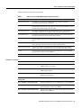
show controllers cable-modem bpkm
To display information about the baseline privacy key management exchange between the
Cisco uBR924 cable access router and the headend CMTS, use the show controllers cable-modem
bpkm command in privileged EXEC mode.
show controllers cable-modem number bpkm
Syntax Description
number
Controller number inside the Cisco uBR924 cable access router.
Defaults
No default behavior or values.
Command Modes
Privileged EXEC
Command History
Release
Modification
11.3 NA
This command was first introduced.
Usage Guidelines
Baseline privacy key management exchanges take place only when both the Cisco uBR924 and the
CMTS are running code images that support baseline privacy, and the privacy class of service is
enabled via the configuration file that is downloaded to the cable access router. Baseline privacy code
images for the Cisco uBR924 contain k1 in the code image name.
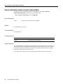
Examples
The following output is displayed when the headend CMTS does not have baseline privacy enabled:
uBR924# show controllers cable-modem 0 bpkm
CM Baseline Privacy Key Management
configuration (in seconds):
authorization wait time:
10
reauthorization wait time: 10
authorization grace time:
600
operational wait time:
1
rekey wait time:
1
tek grace time:
600
authorization rej wait time: 60
kek state:
STATE_B_AUTH_WAIT
sid 4:
tek state: No resources assigned
26
Cisco IOS Release 12.0(5)T
show controllers cable-modem bpkm
Table 3 describes the fields shown in the display.
Table 3
Show Controllers Cable-Modem bpkm Field Descriptions
Field
Description
authorization wait time
The number of seconds the Cisco uBR924 waits for a reply after sending the
Authorization Request message to the CMTS.
reauthorization wait time
The number of seconds the Cisco uBR924 waits for a reply after it has sent an
Authorization Request message to the CMTS in response to a reauthorization request or
an Authorization Invalid message from the CMTS.
authorization grace time
The number of seconds before the current authorization is set to expire that the grace
timer begins, signaling the Cisco uBR924 to begin the reauthorization process.
operational wait time
The number of seconds the TEK state machine waits for a reply from the CMTS after
sending its initial Key Request for its SID’s keying material.
rekey wait time
The number of seconds the TEK state machine waits for a replacement key for this SID
after the TEK grace timer has expired and the request for a replacement key has been
made.
tek grace time
The number of seconds before the current TEK is set to expire that the TEK grace timer
begins, signaling the TEK state machine to request a replacement key.
authorization rej wait time
Number of seconds the Cisco uBR924 waits before sending another Authorization
Request message to the CMTS after it has received an Authorization Reject message.
kek state
The current state of the key encryption key that the CMTS uses to encrypt the traffic
encryption keys it sends to the Cisco uBR924.
tek state
The current state of the traffic encryption key state machine for the specified SID.
Related Commands
Command
Description
show controllers cable-modem
Displays high-level controller information about a Cisco
uBR924 cable access router.
show controllers cable-modem des
Displays information about the Data Encryption Standard
(DES) engine registers.
show controllers cable-modem filters
Displays the registers in the MAC hardware that are used for
filtering received frames.
show controllers cable-modem
lookup-table
Displays the mini-slot lookup table inside a Cisco uBR924.
show controllers cable-modem mac
Displays detailed MAC-layer information for a Cisco uBR924.
show controllers cable-modem phy
Displays the contents of the registers used in the downstream
physical hardware of the Cisco uBR924.
show controllers cable-modem tuner
Displays the settings for the upstream and downstream tuners
used by a Cisco uBR924.
Troubleshooting Tips for the Cisco uBR924 Cable Access Router 27
show controllers cable-modem des
show controllers cable-modem des
To display information about the Data Encryption Standard (DES) engine registers, use the show
controllers cable-modem des command in privileged EXEC mode.
show controllers cable-modem number des
Syntax Description
number
Controller number inside the Cisco uBR924.
Defaults
No default behavior or values.
Command Modes
Privileged EXEC
28
Cisco IOS Release 12.0(5)T
show controllers cable-modem des
Command History
Release
Modification
11.3 NA
This command was first introduced.
Examples
DES engine registers are displayed in the following example:
uBR924# show controllers cable-modem 0 des
downstream des:
ds_des_key_table:
key 0: even 0, odd 0
key 1: even 0, odd 0
key 2: even 0, odd 0
key 3: even 0, odd 0
ds_des_cbc_iv_table:
iv 0: even 0, odd 0
iv 1: even 0, odd 0
iv 2: even 0, odd 0
iv 3: even 0, odd 0
ds_des_sid_table:
sid_1=0x0000, sid_2=0x0000, sid_3=0x0000, sid_4=0x0000
ds_des_sid_enable=0x80, ds_des_ctrl=0x2E
ds_des_sv=0x0F00
ds_unencrypted_length=0x0C
upstream des:
us_des_key_table:
key 0: even 0, odd 0
key 1: even 0, odd 0
key 2: even 0, odd 0
key 3: even 0, odd 0
us_des_cbc_iv_table:
iv 0: even 0, odd 0
iv 1: even 0, odd 0
iv 2: even 0, odd 0
iv 3: even 0, odd 0
pb_req_bytes_to_minislots=0x10
us_des_ctrl=0x00, us_des_sid_1= 0x1234
ds_unencrypted_length=0x0C
Table 4 briefly describes some of the fields shown in the display. For more information, see the
Broadcom documentation for the BCM3300 chip.
Table 4
Show Controllers Cable-Modem DES Field Descriptions
Field
Description
ds_des_key_table
Table showing downstream DES keys.
ds_des_cbc_iv_table
Table of downstream DES Cipher Block Chaining mode information.
ds_des_sid_table
Table showing the SID values to be enabled for DES encryption.
ds_des_sid_enable
Controls which SID entries in the SID table are enabled for encryption. In the above
example, none of the entries are enabled for encryption.
ds_des_ctrl
Control register that controls the operating mode of the downstream DES engine.
ds_des_sv
DES security version register; the range of the version field in the Baseline Privacy
Interface (BPI) extended headers that will be accepted by the hardware. High byte is
upper limit, low byte is lower limit. The Cisco uBR924 will accept versions 0 to 15.
Troubleshooting Tips for the Cisco uBR924 Cable Access Router 29
show controllers cable-modem des
Table 4
Show Controllers Cable-Modem DES Field Descriptions (continued)
Field
Description
ds_unencrypted_length
Specifies the number of bytes that will be unencrypted at the beginning of the MAC
frame. 0x0C means the first 12 bytes are not encrypted, which is what the DOCSIS
Baseline Privacy specification calls for.
us_des_key_table
Table showing upstream DES keys.
us_des_cbc_iv_table
Table of upstream DES Cipher Block Chaining mode information.
us_des_ctrl
Control register that controls the operating mode of the upstream DES engine. The
value 0x24 means that the upstream is configured to enable decryption and to use CBC
mode.
Related Commands
30
Command
Description
show controllers cable-modem
Displays high-level controller information about a Cisco
uBR924 cable access router.
show controllers cable-modem bpkm
Displays information about the baseline privacy key
management exchange between the Cisco uBR924 and the
CMTS.
show controllers cable-modem filters
Displays the registers in the MAC hardware that are used for
filtering received frames.
show controllers cable-modem
lookup-table
Displays the mini-slot lookup table inside a Cisco uBR924.
show controllers cable-modem mac
Displays detailed MAC-layer information for a Cisco uBR924.
show controllers cable-modem phy
Displays the contents of the registers used in the downstream
physical hardware of the Cisco uBR924.
show controllers cable-modem tuner
Displays the settings for the upstream and downstream tuners
used by a Cisco uBR924.
Cisco IOS Release 12.0(5)T
show controllers cable-modem filters
show controllers cable-modem filters
To display the registers in the MAC hardware that are used for filtering received frames, use the show
controllers cable-modem filters command in privileged EXEC mode.
show controllers cable-modem number filters
Syntax Description
number
Controller number inside the Cisco uBR924.
Defaults
No default behavior or values.
Command Modes
Privileged EXEC
Command History
Release
Modification
11.3 NA
This command was first introduced.
Usage Guidelines
Some of the filtering parameters are MAC hardware addresses, Service IDs (SIDs), and upstream
channel IDs.
Troubleshooting Tips for the Cisco uBR924 Cable Access Router 31
show controllers cable-modem filters
Examples
MAC and SID filter information is displayed in the following example:
uBR924# show controllers cable-modem 0 filters
downstream mac message processing:
ds_mac_da_filters:
filter_1=0010.7b43.aa01, filter_2=0000.0000.0000
filter_3=0000.0000.0000, filter_4=0000.0000.0000
ds_mac_da_filter_ctrl=0x71, ds_mac_msg_sof=0x0000
ds_mac_da_mc=01E02F00
map_parser_sids:
sid_1=0x0000, sid_2=0x0000, sid_3=0x0000, sid_4=0x0000
ds_mac_filter_ctrl=0x00, us_channel_id=0x0000
ds_pid=0x0000, mac_msg_proto_ver=FF 00
reg_rang_req_sid=0x0000
downstream data processing:
ds_data_da_filter_table:
filter_1 0010.7b43.aa01, filter_2 0000.0000.0000
filter_3 0000.0000.0000, filter_4 0000.0000.0000
ds_data_da_filter_ctrl=0x61, ds_pdu_sof=0xDEAD
ds_data_da_mc=01000000
upstream processing:
us_ctrl_status=0x04, Minislots per request=0x01
burst_maps:
map[0]=0 map[1]=0 map[2]=0 map[3]=0
bytes_per_minislot_exp=0x04
us_map_parser_minislot_adv=0x03, ticks_per_minislot=0x08, maint_xmit=0x0001
us_sid_table:
sid_1=0x0000, sid_2=0x0000, sid_3=0x0000, sid_4=0x0000
max_re_req=0x0010, rang_fifo=0x00
Table 5 briefly describes some of the fields shown in the display. For more information, see the
Broadcom documentation for the BCM3300 chip.
Table 5
32
Show Controllers Cable-Modem Filters Field Descriptions
Field
Description
ds_mac_da_filters
Shows the MAC address of the cable interface and the MAC address of any Ethernet
MAC it is bridging.
ds_mac_da_filter_ctrl
Downstream MAC filter control for data.
ds_mac_msg_sof
Downstream MAC message start of frame.
ds_mac_da_mc
Downstream MAC control filter for data.
map_parser_sids
Service IDs used for upstream bandwidth allocation.
ds_mac_filter_ctrl
Downstream MAC filter control for MAC messages.
us_channel_id
Upstream channel ID.
ds_pid
Downstream packet ID
mac_msg_proto_ver
Version of the MAC management protocol in use.
reg_rang_req_sid
Service ID (SID) field of the ranging request message.
ds_data_da_filter_table
Downstream data processing filter table.
ds_data_da_filter_ctrl
Downstream data processing filter control.
ds_pdu_sof
Downstream PDU start of frame.
ds_data_da_mc
Downstream data processing MAC control.
us_ctrl_status
Upstream control status.
Cisco IOS Release 12.0(5)T
show controllers cable-modem filters
Table 5
Show Controllers Cable-Modem Filters Field Descriptions (continued)
Field
Description
Minislots per request
Length of each registration request in mini-slots.
burst_maps
Maps the burst profiles saved in the BCM3037 registers to interval usage codes
(IUCs).
bytes_per_minislot_exp
Number of bytes per expansion mini-slot.
ticks_per_minislot
Number of time ticks (6.25-microsecond intervals) in each upstream mini-slot.
maint_xmit
Number of initial maintenance transmit opportunities.
us_sid_table
Upstream service ID table.
max_re_req
Maximum number of registration re-requests allowed.
rang_fifo
Number of ranging requests that can be held in the first-in-first-out (FIFO) buffer.
Related Commands
Command
Description
show controllers cable-modem
Displays high-level controller information about a Cisco
uBR924 cable access router.
show controllers cable-modem bpkm
Displays information about the baseline privacy key
management exchange between the Cisco uBR924 and the
CMTS.
show controllers cable-modem des
Displays information about the Data Encryption Standard
(DES) engine registers.
show controllers cable-modem
lookup-table
Displays the mini-slot lookup table inside a Cisco uBR924.
show controllers cable-modem mac
Displays detailed MAC-layer information for a Cisco uBR924.
show controllers cable-modem phy
Displays the contents of the registers used in the downstream
physical hardware of the Cisco uBR924.
show controllers cable-modem tuner
Displays the settings for the upstream and downstream tuners
used by a Cisco uBR924.
Troubleshooting Tips for the Cisco uBR924 Cable Access Router 33
show controllers cable-modem lookup-table
show controllers cable-modem lookup-table
To display the mini-slot lookup table inside a Cisco uBR924, use the show controllers
cable-modem lookup-table command in privileged EXEC mode.
show controllers cable-modem number lookup-table
Syntax Description
number
Controller number inside the Cisco uBR924.
Defaults
No default behavior or values.
Command Modes
Privileged EXEC
Command History
Release
Modification
11.3 NA
This command was first introduced.
Usage Guidelines
This command displays the details of the lookup table. The driver uses this table to convert the size
of the packets that the Cisco uBR924 wants to transmit into a bandwidth request to the CMTS in
mini-slots. The contents of this table are affected by the upstream symbol rate that is negotiated
between the CMTS and the cable access router.
Use this table to look up the packet size and determine how many mini-slots will be needed.
34
Cisco IOS Release 12.0(5)T
show controllers cable-modem lookup-table
Examples
The mini-slot lookup table is displayed in the following example:
uBR924# show controllers cable-modem 0 lookup-table
Max Burst Size (minislots) = 0x6
Max Burst Length (bytes) = 0x4B
PHY Overhead Lookup Table:
000:
010:
020:
030:
040:
050:
060:
070:
080:
090:
0A0:
0B0:
0C0:
0D0:
0E0:
0F0:
100:
110:
120:
130:
140:
150:
160:
170:
180:
190:
1A0:
1B0:
1C0:
1D0:
1E0:
1F0:
200:
210:
220:
230:
240:
250:
260:
270:
280:
290:
2A0:
2B0:
2C0:
2D0:
2E0:
2F0:
300:
310:
320:
330:
340:
350:
360:
01
06
06
06
06
10
10
10
10
10
10
10
10
10
1F
1F
1F
1F
1F
1F
1F
1F
1F
1F
1F
1F
1F
1F
2D
2D
2D
2D
2D
2D
2D
2D
2D
2D
2D
2D
2D
2D
3C
3C
3C
3C
3C
3C
3C
3C
3C
3C
3C
3C
3C
06
06
06
06
06
10
10
10
10
10
10
10
10
10
1F
1F
1F
1F
1F
1F
1F
1F
1F
1F
1F
1F
1F
1F
2D
2D
2D
2D
2D
2D
2D
2D
2D
2D
2D
2D
2D
2D
3C
3C
3C
3C
3C
3C
3C
3C
3C
3C
3C
3C
3C
06
06
06
06
06
10
10
10
10
10
10
10
10
10
1F
1F
1F
1F
1F
1F
1F
1F
1F
1F
1F
1F
1F
1F
2D
2D
2D
2D
2D
2D
2D
2D
2D
2D
2D
2D
2D
2D
3C
3C
3C
3C
3C
3C
3C
3C
3C
3C
3C
3C
3C
06
06
06
06
06
10
10
10
10
10
10
10
10
10
1F
1F
1F
1F
1F
1F
1F
1F
1F
1F
1F
1F
1F
1F
2D
2D
2D
2D
2D
2D
2D
2D
2D
2D
2D
2D
2D
2D
3C
3C
3C
3C
3C
3C
3C
3C
3C
3C
3C
3C
3C
06
06
06
06
06
10
10
10
10
10
10
10
10
10
1F
1F
1F
1F
1F
1F
1F
1F
1F
1F
1F
1F
1F
1F
2D
2D
2D
2D
2D
2D
2D
2D
2D
2D
2D
2D
2D
2D
3C
3C
3C
3C
3C
3C
3C
3C
3C
3C
3C
3C
3C
06
06
06
06
06
10
10
10
10
10
10
10
10
10
1F
1F
1F
1F
1F
1F
1F
1F
1F
1F
1F
1F
1F
1F
2D
2D
2D
2D
2D
2D
2D
2D
2D
2D
2D
2D
2D
3C
3C
3C
3C
3C
3C
3C
3C
3C
3C
3C
3C
3C
3C
06
06
06
06
06
10
10
10
10
10
10
10
10
10
1F
1F
1F
1F
1F
1F
1F
1F
1F
1F
1F
1F
1F
1F
2D
2D
2D
2D
2D
2D
2D
2D
2D
2D
2D
2D
2D
3C
3C
3C
3C
3C
3C
3C
3C
3C
3C
3C
3C
3C
3C
06
06
06
06
06
10
10
10
10
10
10
10
10
10
1F
1F
1F
1F
1F
1F
1F
1F
1F
1F
1F
1F
1F
1F
2D
2D
2D
2D
2D
2D
2D
2D
2D
2D
2D
2D
2D
3C
3C
3C
3C
3C
3C
3C
3C
3C
3C
3C
3C
3C
3C
06
06
06
06
06
10
10
10
10
10
10
10
10
10
1F
1F
1F
1F
1F
1F
1F
1F
1F
1F
1F
1F
1F
1F
2D
2D
2D
2D
2D
2D
2D
2D
2D
2D
2D
2D
2D
3C
3C
3C
3C
3C
3C
3C
3C
3C
3C
3C
3C
3C
3C
06
06
06
06
06
10
10
10
10
10
10
10
10
10
1F
1F
1F
1F
1F
1F
1F
1F
1F
1F
1F
1F
1F
2D
2D
2D
2D
2D
2D
2D
2D
2D
2D
2D
2D
2D
2D
3C
3C
3C
3C
3C
3C
3C
3C
3C
3C
3C
3C
3C
3C
06
06
06
06
06
10
10
10
10
10
10
10
10
10
1F
1F
1F
1F
1F
1F
1F
1F
1F
1F
1F
1F
1F
2D
2D
2D
2D
2D
2D
2D
2D
2D
2D
2D
2D
2D
2D
3C
3C
3C
3C
3C
3C
3C
3C
3C
3C
3C
3C
3C
3C
06
06
06
06
06
10
10
10
10
10
10
10
10
10
1F
1F
1F
1F
1F
1F
1F
1F
1F
1F
1F
1F
1F
2D
2D
2D
2D
2D
2D
2D
2D
2D
2D
2D
2D
2D
2D
3C
3C
3C
3C
3C
3C
3C
3C
3C
3C
3C
3C
3C
3C
06
06
06
06
10
10
10
10
10
10
10
10
10
10
1F
1F
1F
1F
1F
1F
1F
1F
1F
1F
1F
1F
1F
2D
2D
2D
2D
2D
2D
2D
2D
2D
2D
2D
2D
2D
2D
3C
3C
3C
3C
3C
3C
3C
3C
3C
3C
3C
3C
3C
3C
06
06
06
06
10
10
10
10
10
10
10
10
10
1F
1F
1F
1F
1F
1F
1F
1F
1F
1F
1F
1F
1F
1F
2D
2D
2D
2D
2D
2D
2D
2D
2D
2D
2D
2D
2D
2D
3C
3C
3C
3C
3C
3C
3C
3C
3C
3C
3C
3C
3C
3C
06
06
06
06
10
10
10
10
10
10
10
10
10
1F
1F
1F
1F
1F
1F
1F
1F
1F
1F
1F
1F
1F
1F
2D
2D
2D
2D
2D
2D
2D
2D
2D
2D
2D
2D
2D
2D
3C
3C
3C
3C
3C
3C
3C
3C
3C
3C
3C
3C
3C
3C
06
06
06
06
10
10
10
10
10
10
10
10
10
1F
1F
1F
1F
1F
1F
1F
1F
1F
1F
1F
1F
1F
1F
2D
2D
2D
2D
2D
2D
2D
2D
2D
2D
2D
2D
2D
2D
3C
3C
3C
3C
3C
3C
3C
3C
3C
3C
3C
3C
3C
3C
Troubleshooting Tips for the Cisco uBR924 Cable Access Router 35
show controllers cable-modem lookup-table
370:
380:
390:
3A0:
3B0:
3C0:
3D0:
3E0:
3F0:
400:
410:
420:
430:
440:
450:
460:
470:
480:
490:
4A0:
4B0:
4C0:
4D0:
4E0:
4F0:
500:
510:
520:
530:
540:
550:
560:
570:
580:
590:
5A0:
5B0:
5C0:
5D0:
5E0:
5F0:
600:
610:
620:
630:
3C
4B
4B
4B
4B
4B
4B
4B
4B
4B
4B
4B
4B
4B
5A
5A
5A
5A
5A
5A
5A
5A
5A
5A
5A
5A
5A
5A
68
68
68
68
68
68
68
68
68
68
68
68
68
68
77
77
77
4B
4B
4B
4B
4B
4B
4B
4B
4B
4B
4B
4B
4B
4B
5A
5A
5A
5A
5A
5A
5A
5A
5A
5A
5A
5A
5A
5A
68
68
68
68
68
68
68
68
68
68
68
68
68
68
77
77
77
4B
4B
4B
4B
4B
4B
4B
4B
4B
4B
4B
4B
4B
4B
5A
5A
5A
5A
5A
5A
5A
5A
5A
5A
5A
5A
5A
5A
68
68
68
68
68
68
68
68
68
68
68
68
68
68
77
77
77
4B
4B
4B
4B
4B
4B
4B
4B
4B
4B
4B
4B
4B
4B
5A
5A
5A
5A
5A
5A
5A
5A
5A
5A
5A
5A
5A
5A
68
68
68
68
68
68
68
68
68
68
68
68
68
68
77
77
77
4B
4B
4B
4B
4B
4B
4B
4B
4B
4B
4B
4B
4B
4B
5A
5A
5A
5A
5A
5A
5A
5A
5A
5A
5A
5A
5A
5A
68
68
68
68
68
68
68
68
68
68
68
68
68
68
77
77
77
4B
4B
4B
4B
4B
4B
4B
4B
4B
4B
4B
4B
4B
4B
5A
5A
5A
5A
5A
5A
5A
5A
5A
5A
5A
5A
5A
5A
68
68
68
68
68
68
68
68
68
68
68
68
68
77
77
77
77
4B
4B
4B
4B
4B
4B
4B
4B
4B
4B
4B
4B
4B
4B
5A
5A
5A
5A
5A
5A
5A
5A
5A
5A
5A
5A
5A
5A
68
68
68
68
68
68
68
68
68
68
68
68
68
77
77
77
77
4B
4B
4B
4B
4B
4B
4B
4B
4B
4B
4B
4B
4B
4B
5A
5A
5A
5A
5A
5A
5A
5A
5A
5A
5A
5A
5A
5A
68
68
68
68
68
68
68
68
68
68
68
68
68
77
77
77
77
4B
4B
4B
4B
4B
4B
4B
4B
4B
4B
4B
4B
4B
4B
5A
5A
5A
5A
5A
5A
5A
5A
5A
5A
5A
5A
5A
5A
68
68
68
68
68
68
68
68
68
68
68
68
68
77
77
77
77
4B
4B
4B
4B
4B
4B
4B
4B
4B
4B
4B
4B
4B
4B
5A
5A
5A
5A
5A
5A
5A
5A
5A
5A
5A
5A
5A
68
68
68
68
68
68
68
68
68
68
68
68
68
68
77
77
77
77
4B
4B
4B
4B
4B
4B
4B
4B
4B
4B
4B
4B
4B
4B
5A
5A
5A
5A
5A
5A
5A
5A
5A
5A
5A
5A
5A
68
68
68
68
68
68
68
68
68
68
68
68
68
68
77
77
77
77
4B
4B
4B
4B
4B
4B
4B
4B
4B
4B
4B
4B
4B
4B
5A
5A
5A
5A
5A
5A
5A
5A
5A
5A
5A
5A
5A
68
68
68
68
68
68
68
68
68
68
68
68
68
68
77
77
77
77
4B
4B
4B
4B
4B
4B
4B
4B
4B
4B
4B
4B
4B
4B
5A
5A
5A
5A
5A
5A
5A
5A
5A
5A
5A
5A
5A
68
68
68
68
68
68
68
68
68
68
68
68
68
68
77
77
77
77
PHY Reverse Lookup Table:
00:
08:
10:
18:
20:
28:
30:
38:
40:
48:
50:
58:
60:
68:
70:
78:
80:
36
0000
0000
00DC
00DC
01B8
01B8
0294
0294
0370
0370
044C
044C
0528
0604
0604
06E0
06E0
Cisco IOS Release 12.0(5)T
0000
0000
00DC
00DC
01B8
01B8
0294
0294
0370
0370
044C
044C
0528
0604
0604
06E0
06E0
0000
0000
00DC
00DC
01B8
01B8
0294
0294
0370
0370
044C
0528
0528
0604
0604
06E0
06E0
0000
0000
00DC
00DC
01B8
01B8
0294
0294
0370
044C
044C
0528
0528
0604
0604
06E0
06E0
0000
0000
00DC
00DC
01B8
01B8
0294
0370
0370
044C
044C
0528
0528
0604
0604
06E0
06E0
0000
0000
00DC
00DC
01B8
0294
0294
0370
0370
044C
044C
0528
0528
0604
0604
06E0
06E0
004B
0000
00DC
00DC
01B8
0294
0294
0370
0370
044C
044C
0528
0528
0604
0604
06E0
07BC
0000
0000
00DC
01B8
01B8
0294
0294
0370
0370
044C
044C
0528
0528
0604
06E0
06E0
07BC
4B
4B
4B
4B
4B
4B
4B
4B
4B
4B
4B
4B
4B
5A
5A
5A
5A
5A
5A
5A
5A
5A
5A
5A
5A
5A
5A
68
68
68
68
68
68
68
68
68
68
68
68
68
68
77
77
77
77
4B
4B
4B
4B
4B
4B
4B
4B
4B
4B
4B
4B
4B
5A
5A
5A
5A
5A
5A
5A
5A
5A
5A
5A
5A
5A
5A
68
68
68
68
68
68
68
68
68
68
68
68
68
68
77
77
77
77
4B
4B
4B
4B
4B
4B
4B
4B
4B
4B
4B
4B
4B
5A
5A
5A
5A
5A
5A
5A
5A
5A
5A
5A
5A
5A
5A
68
68
68
68
68
68
68
68
68
68
68
68
68
68
77
77
77
77
show controllers cable-modem lookup-table
88:
90:
98:
A0:
A8:
B0:
B8:
C0:
C8:
D0:
D8:
E0:
E8:
F0:
F8:
07BC
07BC
0898
0898
0974
0974
0A50
0A50
0B2C
0C08
0C08
0CE4
0CE4
0DC0
0DC0
07BC
07BC
0898
0898
0974
0974
0A50
0B2C
0B2C
0C08
0C08
0CE4
0CE4
0DC0
0DC0
07BC
07BC
0898
0898
0974
0A50
0A50
0B2C
0B2C
0C08
0C08
0CE4
0CE4
0DC0
0DC0
07BC
07BC
0898
0974
0974
0A50
0A50
0B2C
0B2C
0C08
0C08
0CE4
0CE4
0DC0
0DC0
07BC
07BC
0898
0974
0974
0A50
0A50
0B2C
0B2C
0C08
0C08
0CE4
0CE4
0DC0
0E9C
07BC
0898
0898
0974
0974
0A50
0A50
0B2C
0B2C
0C08
0C08
0CE4
0DC0
0DC0
0E9C
07BC
0898
0898
0974
0974
0A50
0A50
0B2C
0B2C
0C08
0CE4
0CE4
0DC0
0DC0
0E9C
07BC
0898
0898
0974
0974
0A50
0A50
0B2C
0B2C
0C08
0CE4
0CE4
0DC0
0DC0
0E9C
Related Commands
Command
Description
show controllers cable-modem
Displays high-level controller information about a Cisco
uBR924 cable access router.
show controllers cable-modem bpkm
Displays information about the baseline privacy key
management exchange between the Cisco uBR924 and the
CMTS.
show controllers cable-modem des
Displays information about the Data Encryption Standard
(DES) engine registers.
show controllers cable-modem filters
.Displays the registers in the MAC hardware that are used for
filtering received frames.
show controllers cable-modem mac
Displays detailed MAC-layer information for a Cisco uBR924.
show controllers cable-modem phy
Displays the contents of the registers used in the downstream
physical hardware of the Cisco uBR924.
show controllers cable-modem tuner
Displays the settings for the upstream and downstream tuners
used by a Cisco uBR924.
Troubleshooting Tips for the Cisco uBR924 Cable Access Router 37
show controllers cable-modem mac
show controllers cable-modem mac
To display detailed MAC-layer information for a Cisco uBR924, use the show controllers
cable-modem mac command in privileged EXEC mode.
show controllers cable-modem number mac [errors | hardware | log | resets | state]
Syntax Description
number
Controller number inside the Cisco uBR924.
errors
(Optional) Displays a log of the error events that are reported to SNMP. This keyword
enables you to look at the error events without accessing a MIB.
hardware
(Optional) Displays all MAC hardware registers.
log
(Optional) Displays a history of MAC log messages, up to 1023 entries. This is the same
output that is displayed when using the debug cable-modem mac log command.
resets
(Optional) Extracts all of the reset causes out of the MAC log file and summarizes them
in a mini report.
state
(Optional) Displays a summary of the MAC state.
Defaults
No default behavior or values.
Command Modes
Privileged EXEC
Command History
Release
Modification
11.3 NA
This command was first introduced.
Usage Guidelines
MAC log messages are written to a circular log file even when debugging is not turned on. These
messages include timestamps, events, and information pertinent to these events. Use the show
controllers cable-modem mac log command to view MAC log messages.
If the Cisco uBR924 interface fails to come up or resets periodically, the MAC log will capture what
happened. For example, if an address is not obtained from the DHCP server, an error is logged,
initialization starts over, and the Cisco uBR924 scans for a downstream frequency.
The most useful keywords for troubleshooting a Cisco uBR924 are log, errors, and resets. See
Example 1, Example 2, and Example 3.
38
Cisco IOS Release 12.0(5)T
show controllers cable-modem mac
Example 1
The following sample display shows the MAC log file for a cable-modem interface that has
successfully registered with the CMTS:
uBR924# show controllers cable-modem 0 mac log
00:14:24:
864.124 CMAC_LOG_DRIVER_INIT_IDB_RESET
0x080B7430
00:14:24:
864.128 CMAC_LOG_LINK_DOWN
00:14:24:
864.132 CMAC_LOG_RESET_FROM_DRIVER
00:14:24:
864.134 CMAC_LOG_STATE_CHANGE
wait_for_link_up_state
00:14:24:
864.138 CMAC_LOG_LINK_UP
00:14:24:
864.142 CMAC_LOG_STATE_CHANGE
ds_channel_scanning_state
00:14:24:
864.270 CMAC_LOG_WILL_SEARCH_DS_FREQUENCY_BAND
81/453000000/855000000/6000000
00:14:24:
864.276 CMAC_LOG_WILL_SEARCH_DS_FREQUENCY_BAND
82/93000000/105000000/6000000
00:14:24:
864.280 CMAC_LOG_WILL_SEARCH_DS_FREQUENCY_BAND
83/111025000/117025000/6000000
00:14:24:
864.286 CMAC_LOG_WILL_SEARCH_DS_FREQUENCY_BAND
84/231012500/327012500/6000000
00:14:24:
864.290 CMAC_LOG_WILL_SEARCH_DS_FREQUENCY_BAND
85/333025000/333025000/6000000
00:14:24:
864.294 CMAC_LOG_WILL_SEARCH_DS_FREQUENCY_BAND
86/339012500/399012500/6000000
00:14:24:
864.300 CMAC_LOG_WILL_SEARCH_DS_FREQUENCY_BAND
87/405000000/447000000/6000000
00:14:24:
864.304 CMAC_LOG_WILL_SEARCH_DS_FREQUENCY_BAND
88/123012500/129012500/6000000
00:14:24:
864.310 CMAC_LOG_WILL_SEARCH_DS_FREQUENCY_BAND
89/135012500/135012500/6000000
00:14:24:
864.314 CMAC_LOG_WILL_SEARCH_DS_FREQUENCY_BAND
90/141000000/171000000/6000000
00:14:24:
864.320 CMAC_LOG_WILL_SEARCH_DS_FREQUENCY_BAND
91/219000000/225000000/6000000
00:14:24:
864.324 CMAC_LOG_WILL_SEARCH_DS_FREQUENCY_BAND
92/177000000/213000000/6000000
00:14:24:
864.330 CMAC_LOG_WILL_SEARCH_DS_FREQUENCY_BAND
93/55752700/67753300/6000300
00:14:24:
864.334 CMAC_LOG_WILL_SEARCH_DS_FREQUENCY_BAND
94/79753900/85754200/6000300
00:14:24:
864.340 CMAC_LOG_WILL_SEARCH_DS_FREQUENCY_BAND
95/175758700/211760500/6000300
00:14:24:
864.344 CMAC_LOG_WILL_SEARCH_DS_FREQUENCY_BAND
96/121756000/169758400/6000300
00:14:24:
864.348 CMAC_LOG_WILL_SEARCH_DS_FREQUENCY_BAND
97/217760800/397769800/6000300
00:14:24:
864.354 CMAC_LOG_WILL_SEARCH_DS_FREQUENCY_BAND
98/73753600/115755700/6000300
00:14:24:
864.358 CMAC_LOG_WILL_SEARCH_DS_FREQUENCY_BAND
99/403770100/997799800/6000300
00:14:24:
864.364 CMAC_LOG_WILL_SEARCH_SAVED_DS_FREQUENCY
213000000
00:14:25:
865.450 CMAC_LOG_UCD_MSG_RCVD
1
00:14:25: %LINK-3-UPDOWN: Interface cable-modem0, changed state to up
00:14:26:
866.200 CMAC_LOG_DS_64QAM_LOCK_ACQUIRED
213000000
00:14:26:
866.204 CMAC_LOG_DS_CHANNEL_SCAN_COMPLETED
00:14:26:
866.206 CMAC_LOG_STATE_CHANGE
wait_ucd_state
00:14:26: %LINEPROTO-5-UPDOWN: Line protocol on Interface cable-modem0, changed state to down
00:14:27:
867.456 CMAC_LOG_UCD_MSG_RCVD
1
00:14:29:
869.470 CMAC_LOG_UCD_MSG_RCVD
1
00:14:29:
869.472 CMAC_LOG_ALL_UCDS_FOUND
00:14:29:
869.476 CMAC_LOG_STATE_CHANGE
wait_map_state
00:14:29:
869.480 CMAC_LOG_UCD_NEW_US_FREQUENCY
20000000
00:14:29:
869.484 CMAC_LOG_SLOT_SIZE_CHANGED
8
00:14:29:
869.564 CMAC_LOG_FOUND_US_CHANNEL
1
00:14:31:
871.484 CMAC_LOG_UCD_MSG_RCVD
1
00:14:31:
871.692 CMAC_LOG_MAP_MSG_RCVD
00:14:31:
871.694 CMAC_LOG_INITIAL_RANGING_MINISLOTS
40
00:14:31:
871.696 CMAC_LOG_STATE_CHANGE
ranging_1_state
00:14:31:
871.700 CMAC_LOG_RANGING_OFFSET_SET_TO
9610
00:14:31:
871.704 CMAC_LOG_POWER_LEVEL_IS
32.0 dBmV (commanded)
00:14:31:
871.708 CMAC_LOG_STARTING_RANGING
00:14:31:
871.710 CMAC_LOG_RANGING_BACKOFF_SET
0
00:14:31:
871.714 CMAC_LOG_RNG_REQ_QUEUED
0
00:14:32:
872.208 CMAC_LOG_RNG_REQ_TRANSMITTED
00:14:32:
872.216 CMAC_LOG_RNG_RSP_MSG_RCVD
00:14:32:
872.218 CMAC_LOG_RNG_RSP_SID_ASSIGNED
16
00:14:32:
872.222 CMAC_LOG_ADJUST_RANGING_OFFSET
2853
00:14:32:
872.224 CMAC_LOG_RANGING_OFFSET_SET_TO
12463
00:14:32:
872.228 CMAC_LOG_ADJUST_TX_POWER
8
00:14:32:
872.230 CMAC_LOG_POWER_LEVEL_IS
34.0 dBmV (commanded)
00:14:32:
872.234 CMAC_LOG_STATE_CHANGE
ranging_2_state
00:14:32:
872.238 CMAC_LOG_RNG_REQ_QUEUED
16
00:14:32:
872.848 CMAC_LOG_RNG_REQ_TRANSMITTED
00:14:32:
872.852 CMAC_LOG_RNG_RSP_MSG_RCVD
Troubleshooting Tips for the Cisco uBR924 Cable Access Router 39
show controllers cable-modem mac
00:14:32:
872.856 CMAC_LOG_RANGING_SUCCESS
00:14:32:
872.874 CMAC_LOG_STATE_CHANGE
dhcp_state
00:14:33:
873.386 CMAC_LOG_DHCP_ASSIGNED_IP_ADDRESS
188.188.1.62
00:14:33:
873.388 CMAC_LOG_DHCP_TFTP_SERVER_ADDRESS
4.0.0.32
00:14:33:
873.392 CMAC_LOG_DHCP_TOD_SERVER_ADDRESS
4.0.0.32
00:14:33:
873.396 CMAC_LOG_DHCP_SET_GATEWAY_ADDRESS
00:14:33:
873.398 CMAC_LOG_DHCP_TZ_OFFSET
60
00:14:33:
873.402 CMAC_LOG_DHCP_CONFIG_FILE_NAME
platinum.cm
00:14:33:
873.406 CMAC_LOG_DHCP_ERROR_ACQUIRING_SEC_SVR_ADDR
00:14:33:
873.410 CMAC_LOG_DHCP_COMPLETE
00:14:33:
873.536 CMAC_LOG_STATE_CHANGE
establish_tod_state
00:14:33:
873.546 CMAC_LOG_TOD_REQUEST_SENT
00:14:33:
873.572 CMAC_LOG_TOD_REPLY_RECEIVED
3140961992
00:14:33:
873.578 CMAC_LOG_TOD_COMPLETE
00:14:33:
873.582 CMAC_LOG_STATE_CHANGE
security_association_state
00:14:33:
873.584 CMAC_LOG_SECURITY_BYPASSED
00:14:33:
873.588 CMAC_LOG_STATE_CHANGE
configuration_file_state
00:14:33:
873.592 CMAC_LOG_LOADING_CONFIG_FILE
platinum.cm
00:14:34: %LINEPROTO-5-UPDOWN: Line protocol on Interface cable-modem0, changed state to up
00:14:34:
874.728 CMAC_LOG_CONFIG_FILE_PROCESS_COMPLETE
00:14:34:
874.730 CMAC_LOG_STATE_CHANGE
registration_state
00:14:34:
874.734 CMAC_LOG_REG_REQ_MSG_QUEUED
00:14:34:
874.744 CMAC_LOG_REG_REQ_TRANSMITTED
00:14:34:
874.754 CMAC_LOG_REG_RSP_MSG_RCVD
00:14:34:
874.756 CMAC_LOG_COS_ASSIGNED_SID
1/16
00:14:34:
874.760 CMAC_LOG_RNG_REQ_QUEUED
16
00:14:34:
874.768 CMAC_LOG_REGISTRATION_OK
00
:14:34:
874.770 CMAC_LOG_REG_RSP_ACK_MSG_QUEUED
0
00:14:34:
874.774 CMAC_LOG_STATE_CHANGE
establish_privacy_state
00:14:34:
874.778 CMAC_LOG_PRIVACY_NOT_CONFIGURED
00:14:34:
874.780 CMAC_LOG_STATE_CHANGE
maintenance_state
00:14:34:
874.784 CMAC_LOG_REG_RSP_ACK_MESSAGE_EVENT
00:14:34:
874.788 CMAC_LOG_REG_RSP_ACK_MSG_SENT
If the DHCP server cannot not be reached, the error will look like this in the MAC log:
00:14:32:
00:14:33:
00:14:33:
00:14:33:
00:14:33:
00:14:33:
00:14:33:
00:14:33:
00:14:33:
872.874
873.386
873.388
873.386
873.392
873.396
873.398
873.402
873.406
CMAC_LOG_STATE_CHANGE
CMAC_LOG_RNG_REQ_TRANSMITTED
CMAC_LOG_RNG_RSP_MSG_RCVD
CMAC_LOG_RNG_REQ_TRANSMITTED
CMAC_LOG_RNG_RSP_MSG_RCVD
CMAC_LOG_WATCHDOG_TIMER
CMAC_LOG_RESET_DHCP_WATCHDOG_EXPIRED
CMAC_LOG_STATE_CHANGE
CMAC_LOG_DHCP_PROCESS_KILLED
dhcp_state
reset_interface_state
The fields in this display are explained in the section “Step 4—Interpret the MAC Log File and Take
Action” on page 13.
40
Cisco IOS Release 12.0(5)T
show controllers cable-modem mac
Example 2
MAC error log information is displayed in the following example, which is also reported via SNMP:
uBR924# show controllers cable-modem 0 mac errors
74373.574 R02.0 No Ranging Response received. T3 time-out.
74374.660 R02.0 No Ranging Response received. T3 time-out.
74375.508 R02.0 No Ranging Response received. T3 time-out.
74375.748 R02.0 No Ranging Response received. T3 time-out.
74375.748 R03.0 Ranging Request Retries exhausted.
74376.112 R02.0 No Ranging Response received. T3 time-out.
74376.354 R02.0 No Ranging Response received. T3 time-out.
74376.778 R02.0 No Ranging Response received. T3 time-out.
74377.442 R02.0 No Ranging Response received. T3 time-out.
This output indicates that the Cisco uBR924 acquired a downstream lock, successfully read a UCD,
and successfully read a MAP. However, it was unable to communicate with the CMTS after ranging
through all upstream transmit power levels. The Cisco uBR924 tried to communicate with the CMTS
16 times without success, after which it reset the cable interface to try to find a better downstream
frequency.
If the DHCP server could not be reached, the error would look like this in the MAC error display:
uBR924# show controllers cable-modem 0 mac errors
497989.804 D01.0 Discover sent no Offer received.
498024.046 D01.0 Discover sent no Offer received.
498058.284 D01.0 Discover sent no Offer received.
No available DHCP Server.
No available DHCP Server.
No available DHCP Server.
Example 3
The show controllers cable-modem 0 mac resets command shows only the entries in the MAC log
that begin with the field CMAC_LOG_RESET. Collectively presenting these fields provides you with a
summary of the most recent reasons why the cable interface was reset.
Reset messages and brief explanations are included in the following examples and in Table 6;
however, the reset messages in Table 6 do not commonly occur.
In the following example, the configuration file downloaded from the TFTP server could not be read.
The file might not exist, or the file might have incorrect permissions.
uBR924# show controllers cable-modem 0 mac resets
62526.114 CMAC_LOG_RESET_CONFIG_FILE_READ_FAILED
62564.368 CMAC_LOG_RESET_T4_EXPIRED
62677.178 CMAC_LOG_RESET_CONFIG_FILE_READ_FAILED
62717.462 CMAC_LOG_RESET_CONFIG_FILE_READ_FAILED
62757.746 CMAC_LOG_RESET_CONFIG_FILE_READ_FAILED
62796.000 CMAC_LOG_RESET_T4_EXPIRED
62908.808 CMAC_LOG_RESET_CONFIG_FILE_READ_FAILED
62949.092 CMAC_LOG_RESET_CONFIG_FILE_READ_FAILED
62989.380 CMAC_LOG_RESET_CONFIG_FILE_READ_FAILED
63029.662 CMAC_LOG_RESET_CONFIG_FILE_READ_FAILED
63069.944 CMAC_LOG_RESET_CONFIG_FILE_READ_FAILED
63110.228 CMAC_LOG_RESET_CONFIG_FILE_READ_FAILED
63148.484 CMAC_LOG_RESET_T4_EXPIRED
63261.296 CMAC_LOG_RESET_CONFIG_FILE_READ_FAILED
The following example shows that the DHCP server could not be reached, or that it took too long to
respond.
uBR924# show controllers cable-modem 0 mac resets
497989.804 CMAC_LOG_RESET_DHCP_WATCHDOG_EXPIRED
498024.046 CMAC_LOG_RESET_DHCP_WATCHDOG_EXPIRED
498058.284 CMAC_LOG_RESET_DHCP_WATCHDOG_EXPIRED
Troubleshooting Tips for the Cisco uBR924 Cable Access Router 41
show controllers cable-modem mac
The following example indicates that an event in the cable interface driver caused the interface to
reset. This often occurs because a shut or clear command is currently being issued on the interface.
uBR924# show controllers cable-modem 0 mac resets
527986.444 CMAC_LOG_RESET_FROM_DRIVER
528302.042 CMAC_LOG_RESET_FROM_DRIVER
528346.600 CMAC_LOG_RESET_FROM_DRIVER
528444.494 CMAC_LOG_RESET_FROM_DRIVER
Table 6
Possible but Uncommon Cable Interface Reset Causes
Message
Description
CMAC_LOG_RESET_CONFIG_FILE_PARSE_FAILED
The format of the DOCSIS configuration file acquired
from the TFTP server is not acceptable.
CMAC_LOG_RESET_LOSS_OF_SYNC
Synchronization with the CMTS has been lost (SYNC
messages are not being received).
CMAC_LOG_RESET_T4_EXPIRED
Maintenance ranging opportunities for this
Cisco uBR924 are not being received from the CMTS.
CMAC_LOG_RESET_DHCP_WATCHDOG_EXPIRED
The DHCP server took too long to respond.
CMAC_LOG_RESET_TOD_WATCHDOG_EXPIRED
The Time Of Day server took too long to respond.
CMAC_LOG_RESET_PRIVACY_WATCHDOG_EXPIRED
The baseline privacy exchange with the CMTS took too
long.
CMAC_LOG_RESET_CHANGE_US_WATCHDOG_EXPIRED
The Cisco uBR924 was unable to transmit a response to a
UCC-REQ message.
CMAC_LOG_RESET_SECURITY_WATCHDOG_EXPIRED
The “full security” exchange with the CMTS took too
long.
CMAC_LOG_RESET_CONFIG_FILE_WATCHDOG_EXPIRED
The TFTP server took too long to respond.
CMAC_LOG_RESET_ALL_FREQUENCIES_SEARCHED
All downstream frequencies to be searched have been
searched.
Note This message indicates that downstream
frequencies were found, but the Cisco uBR924 failed to
acquire a downstream lock.
CMAC_LOG_RESET_T2_EXPIRED
Initial ranging opportunities are not being received.
CMAC_LOG_RESET_T3_RETRIES_EXHAUSTED
The CMTS failed too many times to respond to a
RNG-REQ message.
Note After 16 T3 timeouts, the Cisco uBR924 will reset
the cable interface.
CMAC_LOG_RESET_RANGING_ABORTED
The CMTS commanded the Cisco uBR924 to abort the
ranging process.
CMAC_LOG_RESET_NO_MEMORY
The Cisco uBR924 has run out of memory.
CMAC_LOG_RESET_CANT_START_PROCESS
The Cisco uBR924 was unable to start an internal process
necessary to complete ranging and registration.
CMAC_LOG_RESET_CONFIG_FILE_READ_FAILED
The reading of the configuration file from the TFTP
server failed.
Note The file might not exist, or it might have incorrect
permissions.
CMAC_LOG_RESET_AUTHENTICATION_FAILURE
42
Cisco IOS Release 12.0(5)T
The Cisco uBR924 failed authentication as indicated in a
REG-RSP message from the CMTS.
show controllers cable-modem mac
Table 6
Possible but Uncommon Cable Interface Reset Causes (continued)
Message
Description
CMAC_LOG_RESET_SERVICE_NOT_AVAILABLE
The CMTS has failed the Cisco uBR924’s registration
because a required or requested class of service is not
available.
CMAC_LOG_RESET_T6_RETRIES_EXHAUSTED
The CMTS failed too many times to respond to a
REG-REQ message.
CMAC_LOG_RESET_MAINTENANCE_WATCHDOG_DRIVER
The Cisco uBR924 MAC layer failed to detect a change
in the interface driver.
CMAC_LOG_RESET_NET_ACCESS_MISSING
The Network Access parameter is missing from the
DOCSIS configuration file.
CMAC_LOG_RESET_FAILED_WRITE_ACCESS_CONTROL
The Cisco uBR924 was unable to set the Write Access
Control for an SNMP parameter as specified by the
DOCSIS configuration file.
CMAC_LOG_RESET_DHCP_FAILED
The DHCP server did not respond with all the required
values. The required values are: IP address, network
mask, TFTP server IP address, TOD server IP address,
DOCSIS configuration file name, and time zone offset.
CMAC_LOG_RESET_CANT_START_DS_TUNER_PRCESS
The Cisco uBR924 was unable to start the internal
process used to manage the downstream tuner.
CMAC_LOG_RESET_TOO_MANY_DS_LOCKS_LOST
Downstream QAM/FEC lock has been lost too many
times.
CMAC_LOG_RESET_NO_SEND_TO_DS_TUNER_PROCESS
The Cisco uBR924 MAC-layer process was unable to
communicate with the downstream tuner management
process.
CMAC_LOG_RESET_DS_TUNER_WATCHDOG
The downstream tuner process failed to report its
continuing operation for a long period of time.
CMAC_LOG_RESET_UNABLE_TO_SET_MIB_OBJECT
The Cisco uBR924 was unable to set an SNMP parameter
as specified by the DOCSIS configuration file.
CMAC_LOG_RESET_MIB_OBJECT_PROCESS_WATCHDOG
The internal MIB object took too long to process the
entries in the DOCSIS configuration file.
Troubleshooting Tips for the Cisco uBR924 Cable Access Router 43
show controllers cable-modem mac
Example 4
The following example display for the show controllers cable-modem 0 mac hardware command
shows the detailed configuration of the interface driver and the MAC-layer hardware. The most
interesting bit is the station address (hardware address). The MIB statistics reflect the MAC
hardware counters for various events, but these counters are typically reset every few seconds, so
their contents are not accurate in this display.
uBR924# show controllers cable-modem 0 mac hardware
PLD VERSION: 32
BCM3300 unit 0, idb 0x200EB4, ds 0x82D4748, regaddr = 0x800000, reset_mask
0x80
station address 0010.7b43.aa01 default station address 0010.7b43.aa01
MAC mcfilter 01E02F00 data mcfilter 01000000
buffer size 1600
RX data PDU ring with 32 entries at 0x201D40
rx_head = 0x201D40 (0), rx_p = 0x82D4760 (0)
00 pak=0x82DF844 buf=0x227F1A status=0x80 pak_size=0
01 pak=0x82E0BF4 buf=0x22C56A status=0x80 pak_size=0
02 pak=0x82DF454 buf=0x22710A status=0x80 pak_size=0
03 pak=0x82DF64C buf=0x227812 status=0x80 pak_size=0
04 pak=0x82E0024 buf=0x229B3A status=0x80 pak_size=0
05 pak=0x82DBF2C buf=0x21B332 status=0x80 pak_size=0
06 pak=0x82DFE2C buf=0x229432 status=0x80 pak_size=0
07 pak=0x82E0FE4 buf=0x22D37A status=0x80 pak_size=0
08 pak=0x82DF064 buf=0x2262FA status=0x80 pak_size=0
09 pak=0x82DEC74 buf=0x2254EA status=0x80 pak_size=0
10 pak=0x82DEA7C buf=0x224DE2 status=0x80 pak_size=0
11 pak=0x82DE884 buf=0x2246DA status=0x80 pak_size=0
12 pak=0x82DE68C buf=0x223FD2 status=0x80 pak_size=0
13 pak=0x82DE494 buf=0x2238CA status=0x80 pak_size=0
14 pak=0x82DE29C buf=0x2231C2 status=0x80 pak_size=0
15 pak=0x82DE0A4 buf=0x222ABA status=0x80 pak_size=0
16 pak=0x82DDEAC buf=0x2223B2 status=0x80 pak_size=0
17 pak=0x82DDCB4 buf=0x221CAA status=0x80 pak_size=0
18 pak=0x82DDABC buf=0x2215A2 status=0x80 pak_size=0
19 pak=0x82DD8C4 buf=0x220E9A status=0x80 pak_size=0
20 pak=0x82DD6CC buf=0x220792 status=0x80 pak_size=0
21 pak=0x82DD4D4 buf=0x22008A status=0x80 pak_size=0
22 pak=0x82DD2DC buf=0x21F982 status=0x80 pak_size=0
23 pak=0x82DD0E4 buf=0x21F27A status=0x80 pak_size=0
24 pak=0x82DCEEC buf=0x21EB72 status=0x80 pak_size=0
25 pak=0x82DCCF4 buf=0x21E46A status=0x80 pak_size=0
26 pak=0x82DCAFC buf=0x21DD62 status=0x80 pak_size=0
27 pak=0x82DC904 buf=0x21D65A status=0x80 pak_size=0
28 pak=0x82DC70C buf=0x21CF52 status=0x80 pak_size=0
29 pak=0x82DC514 buf=0x21C84A status=0x80 pak_size=0
30 pak=0x82DC31C buf=0x21C142 status=0x80 pak_size=0
31 pak=0x82DC124 buf=0x21BA3A status=0xA0 pak_size=0
RX MAC message ring with 8 entries at 0x201E80
rx_head_mac = 0x201EB0 (6), rx_p_mac = 0x82D480C (6)
00 pak=0x82E0DEC buf=0x22CC72 status=0x80 pak_size=0
01 pak=0x82E021C buf=0x22A242 status=0x80 pak_size=0
02 pak=0x82E060C buf=0x22B052 status=0x80 pak_size=0
03 pak=0x82E11DC buf=0x22DA82 status=0x80 pak_size=0
04 pak=0x82DFC34 buf=0x228D2A status=0x80 pak_size=0
05 pak=0x82E09FC buf=0x22BE62 status=0x80 pak_size=0
06 pak=0x82DEE6C buf=0x225BF2 status=0x80 pak_size=0
07 pak=0x82DFA3C buf=0x228622 status=0xA0 pak_size=0
44
Cisco IOS Release 12.0(5)T
show controllers cable-modem mac
TX BD ring with 8 entries at 0x201FB8, tx_count = 0
tx_head = 0x201FB8 (0), head_txp = 0x82D4888 (0)
tx_tail = 0x201FB8 (0), tail_txp = 0x82D4888 (0)
00 pak=0x000000 buf=0x200000 status=0x00 pak_size=0
01 pak=0x000000 buf=0x200000 status=0x00 pak_size=0
02 pak=0x000000 buf=0x200000 status=0x00 pak_size=0
03 pak=0x000000 buf=0x200000 status=0x00 pak_size=0
04 pak=0x000000 buf=0x200000 status=0x00 pak_size=0
05 pak=0x000000 buf=0x200000 status=0x00 pak_size=0
06 pak=0x000000 buf=0x200000 status=0x00 pak_size=0
07 pak=0x000000 buf=0x200000 status=0x20 pak_size=0
TX PD ring with 8 entries at 0x202038, tx_count = 0
tx_head_pd = 0x202038 (0)
tx_tail_pd = 0x202038 (0)
00 status=0x00 bd_index=0x0000 len=0x0000 hdr_len=0x0000
ehdr: 00 00 00 2E FF FF
01 status=0x00 bd_index=0x0001 len=0x0000 hdr_len=0x0000
ehdr: 00 00 00 2E FF FF
02 status=0x00 bd_index=0x0002 len=0x0000 hdr_len=0x0000
ehdr: 00 00 00 2E FF FF
03 status=0x00 bd_index=0x0003 len=0x0000 hdr_len=0x0000
ehdr: 00 00 00 2E FF FF
04 status=0x00 bd_index=0x0004 len=0x0000 hdr_len=0x0000
ehdr: 00 00 00 2E 00 00
05 status=0x00 bd_index=0x0005 len=0x0000 hdr_len=0x0000
ehdr: 00 00 00 2E 00 00
06 status=0x00 bd_index=0x0006 len=0x0000 hdr_len=0x0000
ehdr: 00 00 00 00 00 00
07 status=0x20 bd_index=0x0007 len=0x0000 hdr_len=0x0000
ehdr: 00 00 00 00 00 00
MIB Statistics
DS fifo full = 0, Rerequests = 0
DS mac msg overruns = 0, DS data overruns = 0
Qualified maps = 0, Qualified syncs = 0
CRC fails = 0, HDR chk fails = 0
Data pdus = 0, Mac msgs = 0
Valid hdrs = 0
BCM3300 Registers:
downstream dma:
ds_data_bd_base=0x001D40, ds_mac_bd_base=0x001E80
ds_data_dma_ctrl=0x98, ds_mac_dma_ctrl=0x98
ds_dma_data_index=0x0000, ds_dma_msg_index=0x0000
upstream dma:
us_bd_base=0x001FB8, us_pd_base=0x002038
us_dma_ctrl=0x00, us_dma_tx_start=0x00
global control and status:
global_ctrl_status=0x00
interrupts:
irq_pend=0x0018, irq_mask=0x00E7
timing recovery circuit:
loop_enable=0x00, minislot_divisor=0x00
K0_ctrl=0x06, K1_ctrl=0x07, acq_threshhold=0x01
err_threshhold=0x04, timeout_threshold=0xFF
nco_bias=0x4F7004F7, ranging_offset=0x00000000
ts_err=0x00, sync_valid=0x00, delta_F=0x00
timeout_err=0x00
spi:
dynamic_ctrl=0x09, static_ctr=0x9F, autonomous=0x01
irq_ack=0x00, spi_cmd=0x51, spi_addr=0x11
spi_data= FF/00/00/00/00/00/00
Troubleshooting Tips for the Cisco uBR924 Cable Access Router 45
show controllers cable-modem mac
burst profiles:
profile 0:
01
00
00
00
profile 1:
01
00
00
00
profile 2:
01
00
00
00
profile 3:
00
00
00
00
19
00
00
00
1D
00
00
00
00
00
00
00
00
00
00
00
00
00
00
00
00
00
00
00
00
00
00
00
00
00
00
00
00
00
00
00
00
00
00
00
00
00
00
00
00
00
00
00
00
00
00
00
00
00
00
00
00
00
00
00
19
00
00
00
1D
00
00
00
03
00
00
00
00
00
00
00
00
00
00
00
00
00
00
00
00
00
00
00
00
00
00
00
00
00
00
00
00
00
00
00
00
00
00
00
00
00
00
00
00
00
00
00
00
00
00
00
00
00
00
00
19
00
00
00
1D
00
00
00
04
00
00
00
00
00
00
00
00
00
00
00
00
00
00
00
00
00
00
00
00
00
00
00
00
00
00
00
00
00
00
00
00
00
00
00
00
00
00
00
00
00
00
00
00
00
00
00
00
00
00
00
00
00
00
00
00
00
00
00
00
00
00
00
00
00
00
00
00
00
00
00
00
00
00
00
00
00
00
00
00
00
00
00
00
00
00
00
00
00
00
00
00
00
00
00
00
00
00
00
00
00
00
00
00
00
00
00
00
00
00
00
Most of the fields in this display are described in Table 2, Show Controllers Cable-Modem Field
Descriptions. Table 7 describes the MIB statistics shown in the display.
Table 7
Show Controllers Cable-Modem MIB Statistics Field Descriptions
Field
Description
DS fifo full
Number of times the downstream receive buffer on the Cisco uBR924 has become full.
Rerequests
Number of registration requests sent by the Cisco uBR924 to the CMTS.
DS mac msg overruns
Number of times the DMA controller has had a downstream MAC message and there
were no free MAC message buffer descriptors to accept the message.
DS data overruns
Number of times the DMA controller has had downstream data and there were no free
data PDU buffer descriptors to accept the data.
Qualified maps
Number of valid MAP messages received by the Cisco uBR924.
Qualified syncs
Number of times the Cisco uBR924 has received synchronization with the downstream
channel.
CRC fails
Number of cyclic redundancy checksums generated by the far-end device that did not
match the checksums calculated from the message portions of the packets received.
HDR check fails
Number of cyclic redundancy checksums generated by the far-end device that did not
match the checksums calculated from the MAC headers of the packets received. The
MAC header CRC is a 16-bit Header Check Sequence (HCS) field that ensures the
integrity of the MAC header even in a collision environment.
Data pdus
Total number of data PDUs (protocol data units) of all types received by the cable
interface.
Mac msgs
Number of MAC messages received by the cable interface.
Valid hdrs
Number of valid MAC headers received by the cable interface.
Below the MIB statistics in the show controllers cable-modem 0 mac hardware display, the
BCM3300 registers section shows the DMA locations of the indicated processing routines of the
Broadcom 3220 MAC chip within the Cisco uBR924.
46
Cisco IOS Release 12.0(5)T
show controllers cable-modem mac
Example 5
The show controllers cable-modem mac state command summarizes the state of the cable MAC
layer and provides a list of downstream search frequency bands and the order in which they are
searched. If the cable MAC layer is in the wait_for_link_up_state, the information shown in the
display corresponds to the last time the interface was up. This allows useful information to be
acquired from this display even though the modem has not been able to range and register. The
normal operational state of the interface is the maintenance_state.
uBR924# show controller cable-modem 0 mac state
MAC State:
maintenance_state
Ranging SID:
5
Registered:
TRUE
Privacy Established:
TRUE
MIB Values:
Mac Resets:
Sync lost:
Invalid Maps:
Invalid UCDs:
Invalid Rng Rsp:
Invalid Reg Rsp:
T1 Timeouts:
T2 Timeouts:
T3 Timeouts:
T4 Timeouts:
Range Aborts:
DS
DS
DS
DS
DS
0
0
0
0
0
0
0
0
4
0
0
ID:
Frequency:
Symbol Rate:
QAM Mode
Search:
88 453000000 855000000
89 93000000 105000000
90 111250000 117250000
91 231012500 327012500
92 333015000 333015000
93 339012500 399012500
94 405000000 447000000
95 123015000 129015000
96 135012500 135012500
97 141000000 171000000
98 219000000 225000000
99 177000000 213000000
US ID:
US Frequency:
US Power Level:
US Symbol Rate:
Ranging Offset:
Mini-Slot Size:
Change Count:
Preamble Pattern:
1
663000000
5056941
64QAM
6000000
6000000
6000000
6000000
6000000
6000000
6000000
6000000
6000000
6000000
6000000
6000000
1
20000000
34.0 (dBmV)
1280000
12460
8
4
CC CC CC CC
A9 17 D9
91 7D 9C
17 D9 C3
F3 F3 F3
F3 F3 F3
88 84 04
88 40 44
CC
C3
35
52
F3
F3
4C
CC
CC
52
22
2F
F3
F3
C4
48
CC
2F
FB
B3
F3
F3
84
4C
CC
B3
38
86
F3
F3
C0
00
CC
86
6A
A4
F3
F3
0C
C4
CC
A4
45
5F
F3
F3
44
40
CC
5F
F6
67
F3
F3
08
80
CC
67
70
0D
F3
F3
08
8C
CC
0D
D4
48
F3
F3
CC
C8
CC
48
8B
BE
F3
33
8C
C0
0D
BE
EC
CE
F3
F7
0C
C8
0D
CE
E1
1A
F3
33
80
04
1A
A9
91
F3
F7
48
88
Troubleshooting Tips for the Cisco uBR924 Cable Access Router 47
show controllers cable-modem mac
Burst Descriptor 0:
Interval Usage Code:
Modulation Type:
Differential Encoding:
Preamble Length:
Preamble Value Offset:
FEC Error Correction:
FEC Codeword Info Bytes:
Scrambler Seed:
Maximum Burst Size:
Guard Time Size:
Last Codeword Length:
Scrambler on/off:
Burst Descriptor 1:
Interval Usage Code:
Modulation Type:
Differential Encoding:
Preamble Length:
Preamble Value Offset:
FEC Error Correction:
FEC Codeword Info Bytes:
Scrambler Seed:
Maximum Burst Size:
Guard Time Size:
Last Codeword Length:
Scrambler on/off:
Burst Descriptor 2:
Interval Usage Code:
Modulation Type:
Differential Encoding:
Preamble Length:
Preamble Value Offset:
FEC Error Correction:
FEC Codeword Info Bytes:
Scrambler Seed:
Maximum Burst Size:
Guard Time Size:
Last Codeword Length:
Scrambler on/off:
Burst Descriptor 3:
Interval Usage Code:
Modulation Type:
Differential Encoding:
Preamble Length:
Preamble Value Offset:
FEC Error Correction:
FEC Codeword Info Bytes:
Scrambler Seed:
Maximum Burst Size:
Guard Time Size:
Last Codeword Length:
Scrambler on/off:
Config File:
Network Access:
Vendor ID:
Baseline Privacy:
Auth. Wait Timeout:
Reauth. Wait Timeout:
Auth. Grace Time:
Op. Wait Timeout:
Retry Wait Timeout:
TEK Grace Time:
Auth. Reject Wait Time:
48
Cisco IOS Release 12.0(5)T
1
1
2
64
56
0
16
338
1
8
1
1
3
1
2
128
0
5
34
338
0
48
1
1
4
1
2
128
0
5
34
338
0
48
1
1
5
1
2
72
48
5
75
338
0
8
1
1
TRUE
0.240.30
10
10
600
1
1
600
60
show controllers cable-modem mac
COS 1:
Assigned SID:
Max Downstream Rate:
Max Upstream Rate:
Upstream Priority:
Min Upstream Rate:
Max Upstream Burst:
Privacy Enable:
Ranging Backoff Start:
Ranging Backoff End:
Data Backoff Start:
Data Backoff End:
IP Address:
Net Mask:
5
4000000
2000000
7
100000
12
TRUE
0 (at initial
4 (at initial
0 (at initial
4 (at initial
0.0.0.0
0.0.0.0
TFTP Server IP Address:
Time Server IP Address:
Config File Name:
Time Zone Offset:
223.255.254.254
188.188.1.5
muck/ebuell/tftp/cm_conf
-28800
ranging)
ranging)
ranging)
ranging)
Table 8 describes the fields shown in the display.
Table 8
Show Controllers Cable-Modem MAC State Field Descriptions
Field
Description
MAC State
Current operational state of the MAC layer of the Cisco uBR924.
Ranging SID
Service ID used for ranging requests.
Registered
Indicates whether or not the Cisco uBR924 is currently registered with the CMTS.
Privacy Established
Indicates whether or not keys for baseline privacy have been exchanged between the
Cisco uBR924 and the CMTS, establishing privacy.
Mac Resets
Number of times the Cisco uBR924 reset or initialized this interface.
Sync lost
Number of times the Cisco uBR924 lost synchronization with the downstream
channel.
Invalid Maps
Number of times the Cisco uBR924 received invalid MAP messages.
Invalid UCDs
Number of times the Cisco uBR924 received invalid UCD messages.
Invalid Rng Rsp
Number of times the Cisco uBR924 received invalid ranging response messages.
Invalid Reg Rsp
Number of times the Cisco uBR924 received invalid registration response messages.
T1 Timeouts
Number of timeouts caused by the Cisco uBR924 not receiving a valid upstream
channel descriptor (UCD) from the CMTS within the specified time.
T2 Timeouts
Number of timeouts caused by the Cisco uBR924 not receiving a maintenance
broadcast for ranging opportunities from the CMTS within a specified time.
T3 Timeouts
Number of timeouts caused by the Cisco uBR924 not receiving a response within a
specified time from the CMTS to a RNG-REQ message during initial maintenance.
T4 Timeouts
Number of timeouts caused by the Cisco uBR924 not receiving a response within a
specified time from the CMTS to a periodic maintenance request.
Range Aborts
Number of times the ranging process was aborted by the CMTS.
DS ID
Identifier of the downstream channel on which this MAC management message has
been transmitted. This identifier is arbitrarily chosen by the CMTS and is only
unique within the MAC-sublayer domain.
DS Frequency
Downstream frequency acquired by the Cisco uBR924 during its last initialization
sequence.
Troubleshooting Tips for the Cisco uBR924 Cable Access Router 49
show controllers cable-modem mac
Table 8
Show Controllers Cable-Modem MAC State Field Descriptions (continued)
Field
Description
DS Symbol Rate
Downstream frequency in symbols per second.
DS QAM Mode
Downstream modulation scheme being used by the Cisco uBR924.
DS Search
Frequency bands scanned by the Cisco uBR924 when searching for a downstream
channel. The Cisco uBR924’s default frequency bands correspond to the North
American EIA CATV channel plan for 6 MHz channel slots between 90 MHz and
858 MHz.
US ID
Identifier of the upstream channel to which this MAC management message refers.
This identifier is arbitrarily chosen by the CMTS and is only unique within the
MAC-sublayer domain.
US Frequency
Transmission frequency used by the Cisco uBR924 in the upstream direction.
US Power Level
Transmit power level of the Cisco uBR924 in the upstream direction.
US Symbol Rate
Upstream frequency in symbols per second.
Ranging Offset
Delay correction (in increments of 6.25 µs/64) applied by the Cisco uBR924 to the
CMTS upstream frame time derived at the Cisco uBR924. Used to synchronize the
upstream transmissions in the time division multiple access (TDMA) scheme, this
value is roughly equal to the round-trip delay of the Cisco uBR924 from the CMTS.
Mini-Slot Size
Size T of the mini-slot for this upstream channel in units of the timebase tick of
6.25 µs. Allowable values are 2, 4, 8, 16, 32, 64, or 128.
Change Count
Incremented by 1 by the CMTS whenever any of the values of this channel descriptor
change. If the value of this count in a sebsequent upstream channel descriptor (UCD)
remains the same, the Cisco uBR924 can quickly decide that the remaining fields
have not changed, and may be able to disregard the remainder of the message.
Preamble Pattern
Byte pattern used for the preamble.
Burst Descriptor:
A compound type/length/value (TLV) encoding that defines, for each type of
upstream usage interval, the physical-layer characteristics that are to be used during
that interval. Each burst descriptor is given an identifying number.
Interval Usage Code
Each upstream transmit burst belongs to a class which is given a number called the
IUC (interval usage code). Bandwidth MAP messages are used by IUC codes to
allocate upstream time slots. The following types are currently defined:
1. Request: bandwidth request slot
2. Request/Data: bandwidth request or data slot
3. Initial Maintenance: initial link registration contention slot
4. Station Maintenance: link keep-alive slot
5. Short Data Grant: short data burst slot
6. Long Data Grant: long data burst slot
50
Modulation Type
Upstream modulation format. (1 = QPSK; 2 = 16QAM)
Differential Encoding
Indicates whether or not differential encoding is used. (1 = yes; 2 = no)
Preamble Length
Length of the preamble in bits. This value must be an integral number of symbols—a
multiple of 2 for QPSK; a multiple of 4 for 16QAM.
FEC Error Correction
Length of the forward error correction in bytes. The range is 0-10 bytes; a value of 0
implies no forward error correction.
FEC Codeword Info Bytes
Number of information bytes in the FEC codeword.
Scrambler Seed
15-bit seed value loaded at the beginning of each burst after the register has been
cleared. Not used if scrambler is off.
Cisco IOS Release 12.0(5)T
show controllers cable-modem mac
Table 8
Show Controllers Cable-Modem MAC State Field Descriptions (continued)
Field
Description
Maximum Burst Size
Maximum number of mini-slots that can be transmitted during this burst type. When
the interval type is Short Data Grant, this value must be greater than 0. If this value is
0, the burst size is limited elsewhere.
Guard Time Size
Amount of time in symbols between the center of the last symbol of a burst and the
center of the first symbol of the preamble of an immediately following burst in an
upstream transmission from the Cisco uBR924 to the CMTS.
Last Codeword Length
Indicates whether or not the length of the last codeword is fixed or shortened.
(1 = fixed; 2 = shortened)
Scrambler on/off
Indicates whether or not a scrambler is enabled in the upstream modulator.
(1 = on; 2 = off)
Network Access
Indicates whether or not the Cisco uBR924 has access to the HFC network.
Vendor ID
Unique identifier specifying the cable modem manufacturer.
Auth. Wait Timeout
Number of seconds the Cisco uBR924 waits for a reply after sending the
Authorization Request message to the CMTS.
Reauth. Wait Timeout
Number of seconds the Cisco uBR924 waits for a reply after it has sent an
Authorization Request message to the CMTS in response to a reauthorization request
or an Authorization Invalid message from the CMTS.
Auth. Grace Time
Number of seconds before the current authorization is set to expire that the grace
timer begins, signaling the Cisco uBR924 to begin the reauthorization process.
Op. Wait Timeout
Number of seconds the TEK state machine waits for a reply from the CMTS after
sending its initial Key Request for its SID’s keying material.
Retry Wait Timeout
Number of seconds the TEK state machine waits for a replacement key for this SID
after the TEK grace timer has expired and the request for a replacement key has been
made.
TEK Grace Time
Number of seconds before the current TEK is set to expire that the TEK grace timer
begins, signaling the TEK state machine to request a replacement key.
Auth. Reject Wait Time
Number of seconds the Cisco uBR924 waits before sending another Authorization
Request message to the CMTS after it has received an Authorization Reject message.
Assigned SID
Service ID assigned by the CMTS for the corresponding service class.
Max Downstream Rate
Maximum downstream rate in bits per second that the CMTS is permitted to forward
to CPE unicast MAC addresses learned or configured as mapping to this
Cisco uBR924. (This does not include MAC packets addressed to broadcast or
multicast MAC addresses.)
Max Upstream Rate
Maximum upstream rate in bits per second that the Cisco uBR924 is permitted to
forward to the RF network. This includes packet PDU data packets addressed to
broadcast or multicast addresses.
Upstream Priority
Relative priority assigned to this service class for data transmission in the upstream
channel. Higher numbers indicate higher priority.
Min Upstream Rate
Date rate in bits per second that will be guaranteed to this service class on the
upstream channel.
Max Upstream Burst
Maximum transmit burst in bytes allowed for this service class on the upstream
channel.
Privacy Enable
Indicates whether or not Baseline Privacy is enabled for this service class.
Ranging Backoff Start
Initial back-off window for initial ranging contention, expressed as a power of 2.
Valid values are from 0 to 15.
Troubleshooting Tips for the Cisco uBR924 Cable Access Router 51
show controllers cable-modem mac
Table 8
Show Controllers Cable-Modem MAC State Field Descriptions (continued)
Field
Description
Ranging Backoff End
Final back-off window for initial ranging contention, expressed as a power of 2.
Valid values are from 0 to 15.
Data Backoff Start
Initial back-off window for contention data and requests, expressed as a power of 2.
Valid values are from 0 to 15.
Data Backoff End
Final back-off window for contention data and requests, expressed as a power of 2.
Valid values are from 0 to 15.
IP Address
IP address of the cable interface.
Net Mask
Subnet mask of the cable interface.
TFTP Server IP Address
IP address of the CMTS TFTP server.
Time Server IP Address
IP address of the CMTS Time of Day (TOD) server.
Config File Name
Name of the configuration file that is downloaded from the TFTP server to provide
the Cisco uBR924 with operational parameters.
Time Zone Offset
Correction received from the DHCP server to synchronize the Cisco uBR924 time
clock with the CMTS.
Related Commands
52
Command
Description
show controllers cable-modem
Displays high-level controller information about a Cisco
uBR924 cable access router.
show controllers cable-modem bpkm
Displays information about the baseline privacy key
management exchange between the Cisco uBR924 and the
CMTS.
show controllers cable-modem des
Displays information about the Data Encryption Standard
(DES) engine registers.
show controllers cable-modem filters
.Displays the registers in the MAC hardware that are used for
filtering received frames.
show controllers cable-modem
lookup-table
Displays the mini-slot lookup table inside a Cisco uBR924.
show controllers cable-modem phy
Displays the contents of the registers used in the downstream
physical hardware of the Cisco uBR924.
show controllers cable-modem tuner
Displays the settings for the upstream and downstream tuners
used by a Cisco uBR924.
Cisco IOS Release 12.0(5)T
show controllers cable-modem phy
show controllers cable-modem phy
To display the contents of the registers used in the downstream physical hardware of the
Cisco uBR924 cable access router, use the show controllers cable-modem phy command in
privileged EXEC mode.
show controllers cable-modem phy {receive | transmit}
Syntax Description
receive
Displays all receiver registers in the downstream physical hardware.
transmit
Displays all transmitter registers in the upstream physical hardware.
Defaults
No default behavior or values.
Command Modes
Privileged EXEC
Command History
Release
Modification
11.3 NA
This command was first introduced.
Usage Guidelines
To understand the output from this command, consult the Broadcom specifications for the BCM3116
and BCM3037 chips.
Examples
Physical receive registers are displayed in the following example:
uBR924# show controllers cable-modem 0 phy receive
BCM3116 Receiver Registers: Chip ID = C2C1
rstctl=
ffectl=3F
dvctl=30
tunset=00
frzctl=20
irqsts=09
idepth=55
tunctl=03
qamctl=1B lmsctl=0B
irqmask=00 stoscm=9E
eqlctl=00 tstctl=02
FFC coefficient registers:
F0=0067FFBC F1=FF880080
F4=00C5FD89 F5=FF6D0485
DFE coefficient
D00=0636031E
D04=0024FF74
D08=0044FFF6
D12=FFD3FFE0
D16=FFFC0024
D20=00020017
registers:
D01=FBDD0314
D05=0015007E
D09=FFE00019
D13=001A000A
D17=0023FFDF
D21=00250001
F2=00C1FEFB
F6=FC95F690
tpctl=00 fmtctl=24
rstctr=00 frzctl2=46
berctl=00 clkset=00
F3=FF75019D
F7=2D280000
D02=0077FD39
D06=000CFFC4
D10=00190005
D14=FFF3FFED
D18=0029FFFF
D22=0007FFF4
D03=001B00C6
D07=FFC0004B
D11=FFD3FFAD
D15=0008FFFD
D19=000D001E
D23=FFF60014
Troubleshooting Tips for the Cisco uBR924 Cable Access Router 53
show controllers cable-modem phy
ldsft=B0EE
ldbbq=00000000
ldbri=F9CDC200
ldsnre=0098AF
ldali=032E00
lddrfo=007E7D
ldif=0D004E
ldaii=E62AF2
lddri=007EF0
ldbbi=00000000
ldbrfo=705A05
FEC correctable error count:
0
FEC uncorrectable error count: 0
Bit Error Rate Count: 0
Physical transmit registers are displayed in the following example:
uBR924# show controllers cable-modem
BCM3037 Transmitter Registers:
part_id
= 3037
rev_id
test_mode
= 00
test_input
test_misc
= 2009
rst
power
= 0000
power_2
port
= 6F
pll
map
= 66
mod
tx_oen_bdly = 14
tx_oen_edly
prbs_cfg
= 00C000
baud
burst
= 0000
if_freq
dac
= 37
tx_config
burst config 0 : prbs_init
fec
pream_len
burst config 1 : prbs_init
fec
pream_len
burst config 2 : prbs_init
fec
pream_len
burst config 3 : prbs_init
fec
burst config 4 : prbs_init
fec
pream_len
burst config 5 : prbs_init
fec
pream_len
Eq Coeff:
00 00 00 00 00 00 00 00 00 00
Preamble
CC CC CC
04 25 01
40 05 01
08 0A 01
03 02 00
01 52 08
04 01 01
01 00 06
54
Cisco IOS Release 12.0(5)T
values:
CC CC 0D
01 01 01
00 06 01
01 0B 01
50 04 02
01 00 09
01 02 01
01 22 07
0D
02
10
02
00
01
02
02
CC
01
07
04
30
30
03
01
CC
02
02
25
05
0A
02
52
CC
03
01
03
01
01
00
08
=
=
=
=
=
=
=
=
=
=
=
=
=
=
=
=
=
0 phy transmit
=
=
=
=
=
=
=
=
=
=
01
00
00
00
F7
28
C8
1A36E3
200000
00
FFFFFF
00
0018
FFFFFE
1C
0000
FFFFFE
1D
0000
FFFFFE
1E
FFFFFE
1F
0000
FFFFFE
0F
0000
rs
qam
offset
rs
qam
offset
rs
qam
offset
rs
qam
rs
qam
offset
rs
qam
offset
00 00 00 00 00 00
CC
02
52
01
00
01
40
01
CC
00
08
01
06
0B
04
00
CC
40
01
01
01
01
02
09
CC
04
01
02
22
02
00
01
CC
02
09
01
07
04
40
30
0D
00
01
02
02
25
05
0A
=
=
=
=
=
=
=
=
=
=
=
=
=
=
=
=
=
343E
01
0000
033B
65
0000
033B
65
0000
033B
65
033B
65
0000
033B
66
0000
show controllers cable-modem phy
Related Commands
Command
Description
show controllers cable-modem
Displays high-level controller information about a Cisco
uBR924 cable access router.
show controllers cable-modem bpkm
Displays information about the baseline privacy key
management exchange between the Cisco uBR924 and the
CMTS.
show controllers cable-modem des
Displays information about the Data Encryption Standard
(DES) engine registers.
show controllers cable-modem filters
.Displays the registers in the MAC hardware that are used for
filtering received frames.
show controllers cable-modem
lookup-table
Displays the mini-slot lookup table inside a Cisco uBR924.
show controllers cable-modem mac
Displays detailed MAC-layer information for a Cisco uBR924.
show controllers cable-modem tuner
Displays the settings for the upstream and downstream tuners
used by a Cisco uBR924.
Troubleshooting Tips for the Cisco uBR924 Cable Access Router 55
show controllers cable-modem tuner
show controllers cable-modem tuner
To display the settings for the upstream and downstream tuners used by a Cisco uBR924 cable access
router, use the show controllers cable-modem tuner command in privileged EXEC mode.
show controllers cable-modem tuner
Syntax Description
There are no key words or arguments for this command.
Defaults
No default behavior or values.
Command Modes
Privileged EXEC
Command History
Release
Modification
11.3 NA
This command was first introduced.
Examples
Typical Cisco uBR924 tuner settings are displayed in the following example. See Table 9 for output
field possibilities and descriptions.
uBR924# show controllers cable-modem 0 tuner
Tuner: status=0x00
Rx: tuner_freq 507000000, symbol_rate 5360736, local_freq 11520000
snr_estimate 17488, ber_estimate 0, lock_threshold 26000
QAM not in lock, FEC not in lock, qam_mode QAM_64
Tx: tx_freq 20000000, power_level 0x3E, symbol_rate 1280000
56
Cisco IOS Release 12.0(5)T
show controllers cable-modem tuner
Table 9
Show Controllers Cable-Modem Tuner Field Descriptions
Field
Description
tuner_freq
Indicates the current downstream frequency.
symbol_rate
Indicates the downstream symbol rate in symbols per second.
local_freq
Frequency on which the transmitter and tuner communicate.
snr_estimate
Signal to noise estimate in dB X 1000.
ber_estimate
Bit error rate estimate (always 0).
lock_threshold
Minimum signal-to-noise ratio (SNR) that the Cisco uBR924 will accept as a valid lock.
QAM status
Indicates if QAM/FEC lock has been acquired and the modulation mode in use.
tx_freq
Upstream frequency sent to the Cisco uBR924 by the CMTS in the UCD message.
power_level
Transmit power level as set in the hardware, given as a hexadecimal value. The units are
unique to the hardware used. Use the show controllers cable-modem 0 mac state
command to see the power level in dBmV.
symbol_rate
Indicates the upstream symbol rate in symbols per second that is negotiated
between the CMTS and the cable access router.
Related Commands
Command
Description
show controllers cable-modem
Displays high-level controller information about a Cisco
uBR924 cable access router.
show controllers cable-modem bpkm
Displays information about the baseline privacy key
management exchange between the Cisco uBR924 and the
CMTS.
show controllers cable-modem des
Displays information about the Data Encryption Standard
(DES) engine registers.
show controllers cable-modem filters
.Displays the registers in the MAC hardware that are used for
filtering received frames.
show controllers cable-modem
lookup-table
Displays the mini-slot lookup table inside a Cisco uBR924.
show controllers cable-modem mac
Displays detailed MAC-layer information for a Cisco uBR924.
show controllers cable-modem phy
Displays the contents of the registers used in the downstream
physical hardware of the Cisco uBR924.
Troubleshooting Tips for the Cisco uBR924 Cable Access Router 57
show controllers cable-modem tuner
Debug Commands
The following debug commands are available to troubleshoot a Cisco uBR924 cable access router:
•
•
•
•
•
•
debug cable-modem bpkm
debug cable-modem bridge
debug cable-modem error
debug cable-modem interrupts
debug cable-modem mac
debug cable-modem map
Note Troubleshooting the Cisco uBR924 cable access router is typically accomplished using the
CMTS at the cable operator’s headend facility; it is rarely done by directly accessing the
Cisco uBR924. For information on troubleshooting the Cisco uBR924 using Cisco uBR7200 series
universal broadband routers, see the document Cisco uBR7246 Universal Broadband Router
Features. Also see the “Related Documents” section on page 2 for additional documents relating to
troubleshooting.
58
Cisco IOS Release 12.0(5)T
debug cable-modem bpkm
debug cable-modem bpkm
To debug baseline privacy information on a Cisco uBR924, use the debug cable-modem bpkm
command in privileged EXEC mode. To turn the debugging messages off, use the no form of this
command.
[no] debug cable-modem bpkm {errors | events | packets}
Syntax Description
errors
Debugs Cisco uBR924 privacy errors.
events
Debugs events related to cable baseline privacy.
packets
Debugs baseline privacy packets.
Defaults
No default behavior or values.
Command Modes
Privileged EXEC
Command History
Release
Modification
11.3 NA
This command was first introduced.
Usage Guidelines
Baseline privacy key management exchanges take place only when both the Cisco uBR924 and the
CMTS are running code images that support baseline privacy, and the privacy class of service is
enabled via the configuration file that is downloaded to the cable access router. Baseline privacy code
images for the Cisco uBR924 contain k1 in the code image name.
Examples
The following example shows debug output when the headend does not have privacy enabled:
uBR924# debug cable-modem bpkm errors
cm_bpkm_fsm(): machine: KEK, event/state: EVENT_4_TIMEOUT/STATE_B_AUTH_WAIT, new state:
STATE_B_AUTH_WAIT
cm_bpkm_fsm(): machine: KEK, event/state: EVENT_4_TIMEOUT/STATE_B_AUTH_WAIT, new state:
STATE_B_AUTH_WAIT
%LINEPROTO-5-UPDOWN: Line protocol on Interface cable-modem0, changed state to down
cm_bpkm_fsm(): machine: KEK, event/state: EVENT_1_PROVISIONED/STATE_A_START, new state:
STATE_B_AUTH_WAIT
%LINEPROTO-5-UPDOWN: Line protocol on Interface cable-modem0, changed state to up
Troubleshooting Tips for the Cisco uBR924 Cable Access Router 59
debug cable-modem bpkm
Related Commands
60
Command
Description
debug cable-modem bridge
Debugs bridge filter processing information on a
Cisco uBR924.
debug cable-modem error
Enables debugging messages for the cable interface driver on a
Cisco uBR924.
debug cable-modem interrupts
Debugs Cisco uBR924 interrupts.
debug cable-modem mac
Troubleshoots the Cisco uBR924 MAC layer.
debug cable-modem map
Displays the timing from MAP messages to sync messages and
the timing between MAP messages.
Cisco IOS Release 12.0(5)T
debug cable-modem bridge
debug cable-modem bridge
Use the debug cable-modem bridge command in privileged EXEC mode to debug bridge filter
processing information on a Cisco uBR924. To turn the debugging messages off, use the no form of
this command.
[no] debug cable-modem bridge
Syntax Description
This command has no keywords or arguments.
Defaults
No default behavior or values.
Command Modes
Privileged EXEC
Command History
Release
Modification
11.3 NA
This command was first introduced.
Usage Guidelines
When the interface is down, all bridge table entries learned on the Ethernet interface are set to discard
because traffic is not bridged until the cable interface has completed initialization. After the interface
(the line protocol) is completely up, bridge table entries learned on the Ethernet interface program
the cable MAC data filters. The cable MAC hardware filters out any received packets whose
addresses are not in the filters. In this way, the cable interface only receives packets addressed to its
own MAC address or an address it has learned on the Ethernet interface.
Examples
The following example shows sample display output for the debug cable-modem bridge privileged
EXEC command:
uBR924# debug cable-modem bridge
%LINEPROTO-5-UPDOWN: Line protocol on Interface cable-modem0, changed state to downshut
cm_tbridge_add_entry(): MAC not initialized, discarding entry: 00e0.fe7a.186fno shut
cm_tbridge_add_entry(): MAC not initialized, discarding entry: 00e0.fe7a.186f
%LINEPROTO-5-UPDOWN: Line protocol on Interface cable-modem0, changed state to up
cm_tbridge_add_entry(): Adding entry 00e0.fe7a.186f to filter 2
Troubleshooting Tips for the Cisco uBR924 Cable Access Router 61
debug cable-modem bridge
Related Commands
62
Command
Description
debug cable-modem bpkm
Debugs baseline privacy information on a Cisco uBR924.
debug cable-modem error
Enables debugging messages for the cable interface driver on a
Cisco uBR924.
debug cable-modem interrupts
Debugs Cisco uBR924 interrupts.
debug cable-modem mac
Troubleshoots the Cisco uBR924 MAC layer.
debug cable-modem map
Displays the timing from MAP messages to sync messages and
the timing between MAP messages.
Cisco IOS Release 12.0(5)T
debug cable-modem error
debug cable-modem error
Use the the debug cable-modem error command in privileged EXEC mode to enable debugging
messages for the cable interface driver. To turn the debugging messages off, use the no form of this
command.
[no] debug cable-modem error
Syntax Description
This command has no keywords or arguments.
Defaults
No default behavior or values.
Command Modes
Privileged EXEC
Command History
Release
Modification
11.3 NA
This command was first introduced.
Usage Guidelines
This command displays detailed output about the sanity checking of received frame formats, the
acquisition of downstream QAM/FEC lock, the receipt or non-receipt of SYNC messages from the
CMTS, reception errors, and bandwidth request failures.
Examples
The following example shows sample display output for the debug cable-modem error privileged
EXEC command:
uBR924#
*Mar 7
*Mar 7
*Mar 7
*Mar 7
*Mar 7
debug cable-modem error
20:16:29: AcquireSync(): Update rate is 100 Hz
20:16:30: 1st Sync acquired after 1100 ms.
20:16:30: Recovery loop is locked (7/9)
20:16:30: 2nd Sync acquired after 100 ms.
20:16:30: Recovery loop is locked (10/15)
Troubleshooting Tips for the Cisco uBR924 Cable Access Router 63
debug cable-modem error
Related Commands
64
Command
Description
debug cable-modem bpkm
Debugs baseline privacy information on a Cisco uBR924.
debug cable-modem bridge
Debugs bridge filter processing information on a
Cisco uBR924.
debug cable-modem interrupts
Debugs Cisco uBR924 interrupts.
debug cable-modem mac
Troubleshoots the Cisco uBR924 MAC layer.
debug cable-modem map
Displays the timing from MAP messages to sync messages and
the timing between MAP messages.
Cisco IOS Release 12.0(5)T
debug cable-modem interrupts
debug cable-modem interrupts
To debug Cisco uBR924 interrupts, use the debug cable-modem interrupts command in privileged
EXEC mode . To turn the debugging messages off, use the no form of this command.
[no] debug cable-modem interrupts
Syntax Description
This command has no keywords or arguments.
Defaults
No default behavior or values.
Command Modes
Privileged EXEC
Command History
Release
Modification
11.3 NA
This command was first introduced.
Examples
The following example shows sample debug output for Cisco uBR924 interrupts.
uBR924# debug cable-modem interrupts
*** BCM3300_rx_mac_msg_interrupt ***
*** BCM3300_rx_mac_msg_interrupt ***
### BCM3300_tx_interrupt ###
*** BCM3300_rx_mac_msg_interrupt ***
### BCM3300_tx_interrupt ###
*** BCM3300_rx_mac_msg_interrupt ***
### BCM3300_tx_interrupt ###
### BCM3300_tx_interrupt ###
### BCM3300_tx_interrupt ###
### BCM3300_tx_interrupt ###
Troubleshooting Tips for the Cisco uBR924 Cable Access Router 65
debug cable-modem interrupts
Related Commands
66
Command
Description
debug cable-modem bpkm
Debugs baseline privacy information on a Cisco uBR924.
debug cable-modem bridge
Debugs bridge filter processing information on a
Cisco uBR924.
debug cable-modem error
Enables debugging messages for the cable interface driver on a
Cisco uBR924.
debug cable-modem mac
Troubleshoots the Cisco uBR924 MAC layer.
debug cable-modem map
Displays the timing from MAP messages to sync messages and
the timing between MAP messages.
Cisco IOS Release 12.0(5)T
debug cable-modem mac
debug cable-modem mac
To troubleshoot the Cisco uBR924 MAC layer, use the debug cable-modem mac command in
privileged EXEC mode. To turn the debugging messages off, use the no form of this command.
[no] debug cable-modem mac {log [verbose] | messages}
Syntax Description
log
Realtime MAC log display.
verbose
(Optional) Displays periodic MAC layer events, such as ranging.
messages
MAC layer management messages.
Defaults
No default behavior or values.
Command Modes
Privileged EXEC
Command History
Release
Modification
11.3 NA
This command was first introduced.
Usage Guidelines
Of all the available debug cable modem commands, the most useful is debug cable-modem mac
log.
MAC log messages are written to a circular log file even when debugging is not turned on. These
messages include timestamps, events, and information pertinent to these events. Enter the debug
cable-modem mac log command to view MAC log messages. If you want to view this information
without entering debug mode, enter the show controllers cable-modem number mac log command.
The same information is displayed by both commands.
If the Cisco uBR924 interface fails to come up or resets periodically, the MAC log will show what
happened. For example, if an address is not obtained from the DHCP server, an error is logged,
initialization starts over, and the Cisco uBR924 scans for a downstream frequency. The debug
cable-modem mac log command displays the log from the oldest to the newest entry.
After initial ranging is successful (dhcp_state has been reached), further RNG-REQ/RNG-RSP
messages and watchdog timer entries are suppressed from output unless the verbose keyword is
used. Note that CMAC_LOG_WATCHDOG_TIMER entries while in the maintenance_state are normal when
using the verbose keyword.
Troubleshooting Tips for the Cisco uBR924 Cable Access Router 67
debug cable-modem mac
Examples
Example 1
This example shows sample display output from the debug cable-modem mac log command. The
fields of the output are the time since bootup, the log message, and in some cases a parameter that
gives more detail about the log entry.
uBR924# debug cable-modem mac log
*Mar 7 01:42:59: 528302.040 CMAC_LOG_LINK_DOWN
*Mar 7 01:42:59: 528302.042 CMAC_LOG_RESET_FROM_DRIVER
*Mar 7 01:42:59: 528302.044 CMAC_LOG_STATE_CHANGE
wait_for_link_up_state
*Mar 7 01:42:59: 528302.046 CMAC_LOG_DRIVER_INIT_IDB_SHUTDOWN
0x08098D02
*Mar 7 01:42:59: 528302.048 CMAC_LOG_LINK_DOWN
*Mar 7 01:43:05: 528308.428 CMAC_LOG_DRIVER_INIT_IDB_RESET
0x08098E5E
*Mar 7 01:43:05: 528308.432 CMAC_LOG_LINK_DOWN
*Mar 7 01:43:05: 528308.434 CMAC_LOG_LINK_UP
*Mar 7 01:43:05: 528308.436 CMAC_LOG_STATE_CHANGE
ds_channel_scanning_state
*Mar 7 01:43:05: 528308.440 CMAC_LOG_WILL_SEARCH_DS_FREQUENCY_BAND
88/453000000/855000000/6000000
*Mar 7 01:43:05: 528308.444 CMAC_LOG_WILL_SEARCH_DS_FREQUENCY_BAND
89/93000000/105000000/6000000
*Mar 7 01:43:05: 528308.448 CMAC_LOG_WILL_SEARCH_DS_FREQUENCY_BAND
90/111250000/117250000/6000000
*Mar 7 01:43:05: 528308.452 CMAC_LOG_WILL_SEARCH_DS_FREQUENCY_BAND
91/231012500/327012500/6000000
*Mar 7 01:43:05: 528308.456 CMAC_LOG_WILL_SEARCH_DS_FREQUENCY_BAND
92/333015000/333015000/6000000
*Mar 7 01:43:05: 528308.460 CMAC_LOG_WILL_SEARCH_DS_FREQUENCY_BAND
93/339012500/399012500/6000000
*Mar 7 01:43:05: 528308.462 CMAC_LOG_WILL_SEARCH_DS_FREQUENCY_BAND
94/405000000/447000000/6000000
*Mar 7 01:43:05: 528308.466 CMAC_LOG_WILL_SEARCH_DS_FREQUENCY_BAND
95/123015000/129015000/6000000
*Mar 7 01:43:05: 528308.470 CMAC_LOG_WILL_SEARCH_DS_FREQUENCY_BAND
96/135012500/135012500/6000000
*Mar 7 01:43:05: 528308.474 CMAC_LOG_WILL_SEARCH_DS_FREQUENCY_BAND
97/141000000/171000000/6000000
*Mar 7 01:43:05: 528308.478 CMAC_LOG_WILL_SEARCH_DS_FREQUENCY_BAND
98/219000000/225000000/6000000
*Mar 7 01:43:05: 528308.482 CMAC_LOG_WILL_SEARCH_DS_FREQUENCY_BAND
99/177000000/213000000/6000000
*Mar 7 01:43:05: 528308.486 CMAC_LOG_WILL_SEARCH_SAVED_DS_FREQUENCY
663000000
*Mar 7 01:43:05: 528308.488 CMAC_LOG_WILL_SEARCH_USER_DS_FREQUENCY
663000000
*Mar 7 01:43:07: 528310.292 CMAC_LOG_DS_64QAM_LOCK_ACQUIRED
663000000
.
528383.992 CMAC_LOG_STATE_CHANGE
registration_state
528384.044 CMAC_LOG_REG_REQ_MSG_QUEUED
528384.050 CMAC_LOG_REG_REQ_TRANSMITTED
528384.052 CMAC_LOG_REG_RSP_MSG_RCVD
528384.078 CMAC_LOG_COS_ASSIGNED_SID
1/4
528384.102 CMAC_LOG_RNG_REQ_QUEUED
4
528384.102 CMAC_LOG_REGISTRATION_OK
528384.102 CMAC_LOG_STATE_CHANGE
establish_privacy_state
528384.102 CMAC_LOG_STATE_CHANGE
maintenance_state
528388.444 CMAC_LOG_RNG_REQ_TRANSMITTED
528388.444 CMAC_LOG_RNG_RSP_MSG_RCVD
528398.514 CMAC_LOG_RNG_REQ_TRANSMITTED
528398.516 CMAC_LOG_RNG_RSP_MSG_RCVD
528408.584 CMAC_LOG_RNG_REQ_TRANSMITTED
528408.586 CMAC_LOG_RNG_RSP_MSG_RCVD
528414.102 CMAC_LOG_WATCHDOG_TIMER
528418.654 CMAC_LOG_RNG_REQ_TRANSMITTED
528418.656 CMAC_LOG_RNG_RSP_MSG_RCVD
528428.726 CMAC_LOG_RNG_REQ_TRANSMITTED
528428.728 CMAC_LOG_RNG_RSP_MSG_RCVD
528438.796 CMAC_LOG_RNG_REQ_TRANSMITTED
528438.798 CMAC_LOG_RNG_RSP_MSG_RCVD
528444.102 CMAC_LOG_WATCHDOG_TIMER
528444.492 CMAC_LOG_LINK_DOWN
528444.494 CMAC_LOG_RESET_FROM_DRIVER
528444.494 CMAC_LOG_STATE_CHANGE
wait_for_link_up_state
528444.494 CMAC_LOG_DRIVER_INIT_IDB_SHUTDOWN
0x08098D02
528444.494 CMAC_LOG_LINK_DOWN
528474.494 CMAC_LOG_WATCHDOG_TIMER
528504.494 CMAC_LOG_WATCHDOG_TIMER
528534.494 CMAC_LOG_WATCHDOG_TIMER
68
Cisco IOS Release 12.0(5)T
debug cable-modem mac
0 events dropped due to lack of a chunk
The line “0 events dropped due to lack of a chunk” at the end of a display indicates that no
log entries were discarded due to a temporary lack of memory. This means the log is accurate and
reliable.
Example 2
The following example compares the output of the debug cable-modem mac log command with the
debug cable-modem mac log verbose command. The verbose keyword displays periodic events
such as ranging.
uBR924# debug cable mac log
Cable Modem mac log debugging is on
uBR924#
uBR924# debug cable mac log verbose
Cable Modem mac log debugging is on (verbose)
uBR924#
574623.810 CMAC_LOG_RNG_REQ_TRANSMITTED
574623.812 CMAC_LOG_RNG_RSP_MSG_RCVD
574627.942 CMAC_LOG_WATCHDOG_TIMER
574633.880 CMAC_LOG_RNG_REQ_TRANSMITTED
574633.884 CMAC_LOG_RNG_RSP_MSG_RCVD
574643.950 CMAC_LOG_RNG_REQ_TRANSMITTED
574643.954 CMAC_LOG_RNG_RSP_MSG_RCVD
574654.022 CMAC_LOG_RNG_REQ_TRANSMITTED
574654.024 CMAC_LOG_RNG_RSP_MSG_RCVD
574657.978 CMAC_LOG_WATCHDOG_TIMER
574664.094 CMAC_LOG_RNG_REQ_TRANSMITTED
574664.096 CMAC_LOG_RNG_RSP_MSG_RCVD
574674.164 CMAC_LOG_RNG_REQ_TRANSMITTED
574674.166 CMAC_LOG_RNG_RSP_MSG_RCVD
uBR924# no debug cable mac log verbose
Cable Modem mac log debugging is off
uBR924#
574684.234 CMAC_LOG_RNG_REQ_TRANSMITTED
574684.238 CMAC_LOG_RNG_RSP_MSG_RCVD
Example 3
The following example shows display output for the debug cable mac messages command. This
command causes received cable MAC management messages to be displayed in a verbose format.
The messages that are displayed are shown below:
uBR924# debug cable-modem mac messages ?
dynsrv
dynamic service mac messages
map
map messages received
reg-req reg-req messages transmitted
reg-rsp reg-rsp messages received
rng-req rng-req messages transmitted
rng-rsp rng-rsp messages received
sync
Sync messages received
ucc-req ucc-req messages received
ucc-rsp ucc-rsp messages transmitted
ucd
UCD messages received
<cr>
The dynsrv keyword displays Dynamic Service Add or Dynamic Service Delete messages during
the off-hook/on-hook transitions of a phone connected to the Cisco uBR924.
Troubleshooting Tips for the Cisco uBR924 Cable Access Router 69
debug cable-modem mac
In addition, transmitted REG-REQs are displayed in hex dump format. The output from this
command is very verbose and is usually not needed for normal interface debugging. The command
is most useful when attempting to attach a Cisco uBR924 cable access router to a CMTS that is not
DOCSIS-qualified.
For a description of the displayed fields of each message, refer to the DOCSIS Radio Frequency
Interface Specification, v1.0 (SP-RFI-I04-980724).
uBR924#
*Mar 7
*Mar 7
*Mar 7
*Mar 7
*Mar 7
*Mar 7
*Mar 7
*Mar 7
*Mar 7
*Mar 7
*Mar 7
*Mar 7
*Mar 7
*Mar 7
*Mar 7
*Mar 7
*Mar 7
*Mar 7
*Mar 7
*Mar 7
*Mar 7
*Mar 7
*Mar 7
*Mar 7
*Mar 7
*Mar 7
*Mar 7
*Mar 7
*Mar 7
*Mar 7
*Mar 7
*Mar 7
*Mar 7
*Mar 7
*Mar 7
*Mar 7
*Mar 7
*Mar 7
*Mar 7
*Mar 7
*Mar 7
*Mar 7
*Mar 7
*Mar 7
*Mar 7
*Mar 7
*Mar 7
*Mar 7
*Mar 7
*Mar 7
*Mar 7
*Mar 7
*Mar 7
*Mar 7
*Mar 7
70
debug cable mac messages
01:44:06:
01:44:06: UCD MESSAGE
01:44:06: ----------01:44:06:
FRAME HEADER
01:44:06:
FC
01:44:06:
MAC_PARM
01:44:06:
LEN
01:44:06:
MAC MANAGEMENT MESSAGE HEADER
01:44:06:
DA
01:44:06:
SA
01:44:06:
msg LEN
01:44:06:
DSAP
01:44:06:
SSAP
01:44:06:
control
01:44:06:
version
01:44:06:
type
01:44:06:
RSVD
01:44:06:
US Channel ID
01:44:06:
Configuration Change Count 01:44:06:
Mini-Slot Size
01:44:06:
DS Channel ID
01:44:06:
Symbol Rate
01:44:06:
Frequency
01:44:06:
Preamble Pattern
01:44:06:
Burst Descriptor 0
01:44:06:
Interval Usage Code
01:44:06:
Modulation Type
01:44:06:
Differential Encoding
01:44:06:
Preamble Length
01:44:06:
Preamble Value Offset
01:44:06:
FEC Error Correction
01:44:06:
FEC Codeword Info Bytes
01:44:06:
Scrambler Seed
01:44:06:
Maximum Burst Size
01:44:06:
Guard Time Size
01:44:06:
Last Codeword Length
01:44:06:
Scrambler on/off
01:44:06:
Burst Descriptor 1
01:44:06:
Interval Usage Code
01:44:06:
Modulation Type
01:44:06:
Differential Encoding
01:44:06:
Preamble Length
01:44:06:
Preamble Value Offset
01:44:06:
FEC Error Correction
01:44:06:
FEC Codeword Info Bytes
01:44:06:
Scrambler Seed
01:44:06:
Maximum Burst Size
01:44:06:
Guard Time Size
01:44:06:
Last Codeword Length
01:44:06:
Scrambler on/off
01:44:06:
Burst Descriptor 2
01:44:06:
Interval Usage Code
01:44:06:
Modulation Type
01:44:06:
Differential Encoding
01:44:06:
Preamble Length
-
Cisco IOS Release 12.0(5)T
0xC2 == MAC Management
0x00
0xD3
01E0.2F00.0001
00E0.1EA5.BB60
C1
0
0
03
01
02 == UCD
0
1
4
8
1
8
20000000
CC CC CC CC CC CC CC CC CC CC CC CC CC CC 0D 0D
1
1 == QPSK
2 == OFF
64
56
0
16
0x0152
1
8
1 == FIXED
1 == ON
3
1 == QPSK
2 == OFF
128
0
5
34
0x0152
0
48
1 == FIXED
1 == ON
4
1 == QPSK
2 == OFF
128
debug cable-modem mac
*Mar
*Mar
*Mar
*Mar
*Mar
*Mar
*Mar
*Mar
*Mar
*Mar
*Mar
*Mar
*Mar
*Mar
*Mar
*Mar
*Mar
*Mar
*Mar
*Mar
*Mar
*Mar
*Mar
*Mar
*Mar
*Mar
*Mar
*Mar
*Mar
*Mar
*Mar
*Mar
.
.
*Mar
*Mar
*Mar
*Mar
*Mar
*Mar
*Mar
*Mar
.
.
*Mar
*Mar
*Mar
*Mar
*Mar
*Mar
*Mar
*Mar
*Mar
*Mar
*Mar
*Mar
*Mar
*Mar
*Mar
*Mar
*Mar
*Mar
*Mar
*Mar
*Mar
7
7
7
7
7
7
7
7
7
7
7
7
7
7
7
7
7
7
7
7
7
7
7
7
7
7
7
7
7
7
7
7
01:44:06:
Preamble Value Offset
01:44:06:
FEC Error Correction
01:44:06:
FEC Codeword Info Bytes
01:44:06:
Scrambler Seed
01:44:06:
Maximum Burst Size
01:44:06:
Guard Time Size
01:44:06:
Last Codeword Length
01:44:06:
Scrambler on/off
01:44:06:
Burst Descriptor 3
01:44:06:
Interval Usage Code
01:44:06:
Modulation Type
01:44:06:
Differential Encoding
01:44:06:
Preamble Length
01:44:06:
Preamble Value Offset
01:44:06:
FEC Error Correction
01:44:06:
FEC Codeword Info Bytes
01:44:06:
Scrambler Seed
01:44:06:
Maximum Burst Size
01:44:06:
Guard Time Size
01:44:06:
Last Codeword Length
01:44:06:
Scrambler on/off
01:44:06:
01:44:06:
01:44:06: MAP MESSAGE
01:44:06: ----------01:44:06:
FRAME HEADER
01:44:06:
FC
01:44:06:
MAC_PARM
01:44:06:
LEN
01:44:06:
EHDR
01:44:06:
MAC MANAGEMENT MESSAGE HEADER
01:44:06:
DA
-
7
7
7
7
7
7
7
7
01:44:17: RNG-RSP MESSAGE
01:44:17: --------------01:44:17:
FRAME HEADER
01:44:17:
FC
- 0xC2 == MAC Management
01:44:17:
MAC_PARM
- 0x00
01:44:17:
LEN
- 0x2B
01:44:17:
MAC MANAGEMENT MESSAGE HEADER
01:44:17:
DA
- 00F0.1EB2.BB61
7
7
7
7
7
7
7
7
7
7
7
7
7
7
7
7
7
7
7
7
7
01:44:20:
01:44:20:
01:44:20:
01:44:20:
01:44:20:
01:44:20:
01:44:20:
01:44:20:
01:44:20:
01:44:20:
01:44:20:
01:44:20:
01:44:20:
01:44:20:
01:44:20:
01:44:20:
01:44:20:
01:44:20:
01:44:20:
01:44:20:
01:44:20:
REG-REQ MESSAGE
--------------C20000A5 000000E0
BB610093 00000301
1F010101 0204003D
04010705 04000186
080300F0 1E112A01
00000A03 04000002
04000000 01060400
3C2B0563 6973636F
61086FD5 5C9D756F
204D4943 202D2D2D
00000503 010100
REG-RSP MESSAGE
--------------FRAME HEADER
FC
MAC_PARM
LEN
1EA5BB60
06000004
09000304
A0060200
04000000
58040400
00025807
06105E4F
7B730710
2D2D2D2D
0
5
34
0x0152
0
48
1 == FIXED
1 == ON
5
1 == QPSK
2 == OFF
72
48
5
75
0x0152
0
8
1 == FIXED
1 == ON
0xC3 == MAC Management with Extended Header
0x02
0x42
0x00 0x00
01E0.2F00.0001
00F01EB2
03010104
001E8480
0C070101
0A020400
00000105
04000000
C908C655
434D5453
0C040000
- 0xC2 == MAC Management
- 0x00
- 0x29
Troubleshooting Tips for the Cisco uBR924 Cable Access Router 71
debug cable-modem mac
*Mar
*Mar
7 01:44:20:
7 01:44:20:
MAC MANAGEMENT MESSAGE HEADER
DA
- 00F0.1EB2.BB61
Related Commands
72
Command
Description
debug cable-modem bpkm
Debugs baseline privacy information on a Cisco uBR924.
debug cable-modem bridge
Debugs bridge filter processing information on a
Cisco uBR924.
debug cable-modem error
Enables debugging messages for the cable interface driver on a
Cisco uBR924.
debug cable-modem interrupts
Debugs Cisco uBR924 interrupts.
debug cable-modem map
Displays the timing from MAP messages to sync messages and
the timing between MAP messages.
Cisco IOS Release 12.0(5)T
debug cable-modem map
debug cable-modem map
To display the timing from MAP messages to sync messages and the timing between MAP messages
on a Cisco uBR924 cable access router, use the debug cable-modem map command in privileged
EXEC mode. To turn the debugging messages off, use the no form of this command.
[no] debug cable-modem map
Syntax Description
This command has no keywords or arguments.
Defaults
No default behavior or values.
Command Modes
Privileged EXEC
Command History
Release
Modification
11.3 NA
This command was first introduced.
Examples
The following example shows display output for the debug cable-modem map privileged EXEC
command.
uBR924# debug cable-modem map
Cable Modem MAP debugging is on
uBR924#
*Mar 7 20:12:08: 595322.942: Min
*Mar 7 20:12:08: 595322.944: Max
*Mar 7 20:12:08: 595322.982: Min
*Mar 7 20:12:08: 595323.110: Max
*Mar 7 20:12:08: 595323.262: Min
*Mar 7 20:12:08: 595323.440: Max
*Mar 7 20:12:09: 595323.872: Min
MAP
map
MAP
map
MAP
map
MAP
to
to
to
to
to
to
to
sync=72
map time is 40
sync=63
map time is 41
sync=59
map time is 46
sync=58
Troubleshooting Tips for the Cisco uBR924 Cable Access Router 73
debug cable-modem map
Related Commands
74
Command
Description
debug cable-modem bpkm
Debugs baseline privacy information on a Cisco uBR924.
debug cable-modem bridge
Debugs bridge filter processing information on a
Cisco uBR924.
debug cable-modem error
Enables debugging messages for the cable interface driver on a
Cisco uBR924.
debug cable-modem interrupts
Debugs Cisco uBR924 interrupts.
debug cable-modem mac
Troubleshoots the Cisco uBR924 MAC layer.
Cisco IOS Release 12.0(5)T