1
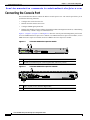
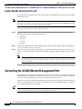
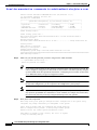
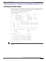
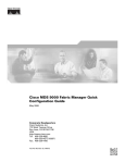
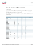
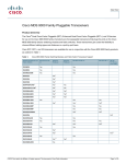
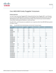
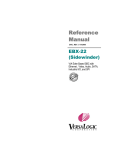
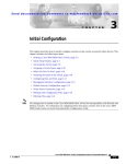
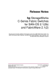
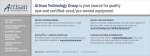
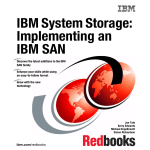
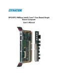
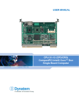
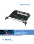
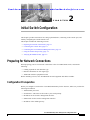
Se n d d o c u m e n t a t i o n c o m m e n t s t o m d s f e e d b a ck - d o c @ c i s c o . c o m
C H A P T E R
2
Initial Switch Configuration
This chapter provides instructions for setting up the hardware, connecting to the console port, and
initially configuring the switch from the CLI.
This chapter includes the following sections:
•
Preparing for Network Connections, page 2-1
•
Connecting the Console Port, page 2-2
•
Connecting the 10/100 Ethernet Management Port, page 2-4
•
Using the Switch Setup Utility, page 2-5
•
Verifying the Module Status, page 2-9
Preparing for Network Connections
When preparing your site for network connections to the Cisco MDS 9000 switch, consider the
following:
•
Cabling required for each interface type
•
Distance limitations for each signal type
•
Additional interface equipment needed
Before installing a device, have all additional external equipment and cables available.
Configuration Prerequisites
Before you configure a switch in the Cisco MDS 9000 Family for the first time, make sure you have the
following information:
•
Administrator password.
•
Switch name—This name is also used as your switch prompt.
•
IP address for the switch’s management interface.
•
Subnet mask for the switch's management interface.
•
IP address of the default gateway.
Cisco MDS 9000 Family Fabric Manager Quick Configuration Guide
OL-7765-04
2-1
Chapter 2
Initial Switch Configuration
Connecting the Console Port
Se n d d o c u m e n t a t i o n c o m m e n t s t o m d s f e e d b a ck - d o c @ c i s c o . c o m
Connecting the Console Port
This section describes how to connect the RS-232 console port to a PC. The console port allows you to
perform the following functions:
•
Configure the switch from the CLI.
•
Monitor network statistics and errors.
•
Configure SNMP agent parameters.
•
Manage downloading software updates (through the Ethernet management interface) or distributing
Flash memory software images to attached devices.
Figure 2-1, Figure 2-2, Figure 2-3 and Figure 2-4 show the console port and management port located
on a Cisco MDS 9500 series supervisor-1 module, Cisco MDS 9500 series supervisor-2 module, a Cisco
MDS 9200 series supervisor module, and Cisco MDS 9100 series supervisor module.
Figure 2-1
Cisco MDS 9500 Series Supervisor Module
2
140573
1
1
Console port
2
MGMT 10/100 Ethernet port (with integrated link and activity LEDs)
Figure 2-2
Cisco MDS 9500 Series Supervisor-2 Module
154318
2
1
1
Status, System, Active, and Pwr Mgmt LEDs
4
MGMT 10/100/1000 Ethernet port (with integrated Link and Activity LEDs)
Cisco MDS 9000 Family Fabric Manager Quick Configuration Guide
2-2
OL-7765-04
Chapter 2
Initial Switch Configuration
Connecting the Console Port
Se n d d o c u m e n t a t i o n c o m m e n t s t o m d s f e e d b a ck - d o c @ c i s c o . c o m
Connecting the Console Cable to a Cisco MDS 9200 Series Switch
S
SY
ST
EM
ST
AT
U
MDS 9216i
RE
SE
T
1
CONSOLE
2
MGMT 10/100
COM1
140571
Figure 2-3
1
Console port
2
MGMT 10/100 Ethernet port (with integrated link and activity LEDs)
Figure 2-4
2
140572
1
Connecting the Console Cable to a Cisco MDS 9100 Series Switch
1
Console port
2
MGMT 10/100 Ethernet port (with integrated link and activity LEDs)
Cisco MDS 9000 Family Fabric Manager Quick Configuration Guide
OL-7765-04
2-3
Chapter 2
Initial Switch Configuration
Connecting the 10/100 Ethernet Management Port
Se n d d o c u m e n t a t i o n c o m m e n t s t o m d s f e e d b a ck - d o c @ c i s c o . c o m
Connecting the Console Port to a PC
You can connect the console port to a PC serial port for local administrative access to the Cisco MDS
9000 Family switch.
Note
The PC must support VT100 terminal emulation. The terminal emulation software—frequently a PC
application such as HyperTerminal Plus—makes communication between the Cisco MDS 9000 Family
switch and your PC possible during setup and configuration.
To connect the console port to a PC, follow these steps:
Step 1
Configure the baud rate and character format of the PC terminal emulation program to match the
following management port default characteristics:
•
9600 baud
•
8 data bits
•
1 stop bit
•
No parity
Step 2
Connect the supplied RJ-45 to DB-9 female adapter or RJ-45 to DB-25 female adapter (depending on
your PC connection) to the PC serial port.
Step 3
Connect one end of the supplied console cable (a rollover RJ-45 to RJ-45 cable) to the console port. (See
Figure 2-4.) Connect the other end to the RJ-45 to DB-9 (or RJ-45 to DB-25) adapter at the PC serial
port.
Note
If you are using a Cisco MDS 9500 Series switch that has multiple supervisor modules, connect
the console port to the active supervisor module. The active supervisor is the module with the
green Active LED.
Connecting the 10/100 Ethernet Management Port
The autosensing 10/100 Ethernet management port is located on the left side of the front panel (labeled
10/100 MGMT), to the right of the console port (see Figure 2-1, Figure 2-3, and Figure 2-4). This port
is used for out-of-band management of the Cisco MDS 9000 Family switches.
Make sure to connect the Ethernet management ports of both supervisor modules on a MDS 9500 Series
switch. Even though there are two Ethernet connections, only one management IP address is required
for a switch with dual supervisor modules.
Tip
The two Ethernet connections should be connected to ports in different slots on the same LAN switch,
or the connections should be split between two different LAN switches.
Cisco MDS 9000 Family Fabric Manager Quick Configuration Guide
2-4
OL-7765-04
Chapter 2
Initial Switch Configuration
Connecting to the MGMT 10/100/1000 Ethernet Port
Se n d d o c u m e n t a t i o n c o m m e n t s t o m d s f e e d b a ck - d o c @ c i s c o . c o m
If only the active supervisor module is connected to the LAN and an event occurs that causes a system
switchover (such as a software upgrade), the switch becomes unmanageable through the Ethernet port
after the active supervisor module reboots and the standby supervisor module becomes the active
supervisor module.
Use modular, RJ-45 cables to connect the 10/100 Ethernet management port to external hubs and
switches.
Connecting to the MGMT 10/100/1000 Ethernet Port
The Supervisor-2 module supports an autosensing MGMT 10/100/1000 Ethernet port (labeled “MGMT
10/100/1000”) and has an RJ-45 interface. You can use this port to access and manage the switch by IP
address, such as through Cisco Fabric Manager.
Use a modular, RJ-45, straight-through UTP cable to connect the MGMT 10/100/1000 Ethernet port to
an Ethernet switch port or hub.
Using the Switch Setup Utility
The switch setup utility helps you configure the switch through the CLI. To configure the switch, follow
these steps:
Step 1
Verify the following physical connections for the new Cisco MDS 9000 Family switch (see Figure 2-4):
•
The console port is physically connected to a computer terminal (or terminal server).
•
The management 10/100 Ethernet port (mgmt0) is connected to an external hub, switch, or router.
Refer to the hardware installation guide for your specific product.
Tip
Save the host ID information for future use (for example, to enable licensed features). The host
ID information is provided in the Proof of Purchase document that accompanies the switch.
Step 2
Verify that the default console port parameters are identical to those parameters of the computer terminal
(or terminal server) attached to the switch console port (see the “Connecting the Console Port to a PC”
section on page 2-4).
Step 3
Power on the switch. The switch boots automatically.
Note
If the switch boots to the loader> or switch(boot) prompt, contact your storage vendor support
organization for technical assistance.
After powering on the switch, you see the following output:
General Software Firmbase[r] SMM Kernel 1.1.1002 Aug
General Software, Inc.
6 2003 22:19:14 Copyright (C) 2002
Firmbase initialized.
00000589K Low Memory Passed
01042304K Ext Memory Passed
Wait.....
Cisco MDS 9000 Family Fabric Manager Quick Configuration Guide
OL-7765-04
2-5
Chapter 2
Initial Switch Configuration
Using the Switch Setup Utility
Se n d d o c u m e n t a t i o n c o m m e n t s t o m d s f e e d b a ck - d o c @ c i s c o . c o m
General Software Pentium III Embedded BIOS 2000 (tm) Revision 1.1.(0)
(C) 2002 General Software, Inc.ware, Inc.
Pentium III-1.1-6E69-AA6E
+------------------------------------------------------------------------------+
|
System BIOS Configuration, (C) 2002 General Software, Inc.
|
+---------------------------------------+--------------------------------------+
| System CPU
: Pentium III
| Low Memory
: 630KB
|
| Coprocessor
: Enabled
| Extended Memory
: 1018MB
|
| Embedded BIOS Date
: 10/24/03
| ROM Shadowing
: Enabled
|
+---------------------------------------+--------------------------------------+
Loader Loading stage1.5.
Loader loading, please wait...
Auto booting bootflash:/m9500-sf1ek9-kickstart-mz.2.1.1a.bin bootflash:/m9500-s
f1ek9-mz.2.1.1a.bin...
Booting kickstart image:
bootflash:/m9500-sf1ek9-kickstart-mz.2.1.1a.bin...................Image verification OK
Starting kernel...
INIT: version 2.78 booting
Checking all filesystems..... done.
Loading system software
Uncompressing system image: bootflash:/m9500-sf1ek9-mz.2.1.1a.bin
CCCCCCCCCCCCCCCCCCCCCCCCCCCCCCCCCCCCCCCCCCCCCCCCCCCCCCCCCCCCCCCCCCCCCCCCCCCCCCCCCCCCCCCCCC
INIT: Entering runlevel: 3
Step 4
Make sure you enter the password you wish to assign for the admin username.
---- System Admin Account Setup ---Enter the password for "admin":
Step 5
Tip
If you create a password that is short and easy to decipher, then your password is rejected. Be
sure to configure a strong password. Passwords are case-sensitive. You must explicitly configure
a password that meets the requirements listed in the “Configuring User Accounts” section in the
Cisco MDS 9000 Family CLI Quick Configuration Guide.
Note
If you are running the switch setup utility for the first-time, it starts automatically. If this is not
the first-time configuration, you are required to enter setup at the system prompt.
Note
If you do not wish to answer a previously configured question, or if you wish to skip answers to
any questions, press Enter. If a default answer is not available (for example, the switch name),
the switch uses what was previously configured and skips to the next question.
Enter yes to enter setup mode.
This setup utility will guide you through the basic configuration of the system. Setup
configures only enough connectivity for management of the system.
*Note: setup is mainly used for configuring the system initially,
when no configuration is present. So setup always assumes system
defaults and not the current system configuration values.
Press Enter at anytime to skip a dialog. Use ctrl-c at anytime
to skip the remaining dialogs.
Cisco MDS 9000 Family Fabric Manager Quick Configuration Guide
2-6
OL-7765-04
Chapter 2
Initial Switch Configuration
Using the Switch Setup Utility
Se n d d o c u m e n t a t i o n c o m m e n t s t o m d s f e e d b a ck - d o c @ c i s c o . c o m
Would you like to enter the basic configuration dialog (yes/no): yes
The switch setup utility guides you through the basic configuration process. Press Ctrl-C at any prompt
to end the configuration process.
Step 6
Enter no (no is the default) to not create any additional accounts.
Create another login account (yes/no) [n]: no
Step 7
Enter no (no is the default) to not configure any read-only SNMP community strings.
Configure read-only SNMP community string (yes/no) [n]: no
Step 8
Enter no (no is the default) to not configure any read-write SNMP community strings.
Configure read-write SNMP community string (yes/no) [n]: no
Step 9
Enter a name for the switch.
Note
The switch name is limited to 32 alphanumeric characters. The default is switch.
Enter the switch name: switch_name
Step 10
Enter yes (yes is the default) to configure the out-of-band management configuration.
Continue with Out-of-band (mgmt0) management configuration? (yes/no) [y]: yes
a.
Enter the IP address for the mgmt0 interface.
Mgmt0 IP address : mgmt_IP_address
b.
Enter the netmask for the mgmt0 interface in the xxx.xxx.xxx.xxx format.
Mgmt0 IP netmask : xxx.xxx.xxx.xxx
Step 11
Enter yes (yes is the default) to configure the default gateway (recommended).
Configure the default-gateway: (yes/no) [y]: yes
Step 12
Enter the default gateway IP address.
IP address of the default-gateway: default_gateway
Step 13
Enter no (no is the default) to configure advanced IP options such as in-band management, static routes,
default network, DNS, and domain name.
Configure Advanced IP options (yes/no)? [n]: no
Step 14
Enter yes (yes is the default) to enable Telnet service.
Enable the telnet service? (yes/no) [y]: yes
Step 15
Enter no (no is the default) to not enable the SSH service.
Enable the ssh service? (yes/no) [n]: no
Step 16
Enter no (no is the default) to not configure the NTP server.
Configure the ntp server? (yes/no) [n]: no
Step 17
Enter noshut (shut is the default) to configure the default switch port interface to the noshut state.
Configure default switchport interface state (shut/noshut) [shut]: noshut
Cisco MDS 9000 Family Fabric Manager Quick Configuration Guide
OL-7765-04
2-7
Chapter 2
Initial Switch Configuration
Using the Switch Setup Utility
Se n d d o c u m e n t a t i o n c o m m e n t s t o m d s f e e d b a ck - d o c @ c i s c o . c o m
Step 18
Enter on (on is the default) to configure the switch port trunk mode.
Configure default switchport trunk mode (on/off/auto) [on]: on
Step 19
Enter deny (deny is the default) to configure a default zone policy configuration.
Configure default zone policy (permit/deny) [deny]: deny
This step denies traffic flow for all members of the default zone.
Step 20
Enter yes (no is the default) to enable a full zone set distribution (refer to the Cisco MDS 9000 Family
CLI Quick Configuration Guide).
Enable full zoneset distribution (yes/no) [n]: yes
You see the new configuration. Review and edit the configuration that you have just entered.
Step 21
Enter no (no is the default) if you are satisfied with the configuration.
The following configuration will be applied:
switchname switch_name
interface mgmt0
ip address mgmt_IP_address
subnetmask mgmt0_ip_netmask
no shutdown
ip default-gateway default_gateway
telnet server enable
no ssh server enable
no system default switchport shutdown
system default switchport trunk mode on
no zone default-zone permit vsan 1-4093
zoneset distribute full vsan 1-4093
Would you like to edit the configuration? (yes/no) [n]: no
Step 22
Enter yes (yes is the default) to use and save this configuration.
Use this configuration and save it? (yes/no) [y]: yes
Caution
If you do not save the configuration at this point, your changes will not be updated the next
time that the switch is rebooted. Type yes to save the new configuration to ensure that the
kickstart and system images are also automatically configured.
Cisco MDS 9000 Family Fabric Manager Quick Configuration Guide
2-8
OL-7765-04
Chapter 2
Initial Switch Configuration
Verifying the Module Status
Se n d d o c u m e n t a t i o n c o m m e n t s t o m d s f e e d b a ck - d o c @ c i s c o . c o m
Verifying the Module Status
Before you proceed with further configuration of the switch, ensure that the modules in the chassis are
functioning as designed. To verify the status of a module at any time, issue the show module command.
All the hardware that was physically installed should be displayed.
A sample output of the show module command follows:
switch# show module
Mod Ports Module-Type
--- ----- -------------------------------2
32
1/2 Gbps FC Module
3
16
1/2 Gbps FC Module
4
8
IP Storage Services Module
5
0
Supervisor/Fabric-1
6
0
Supervisor/Fabric-1
7
0
Caching Services Module
9
32
Advanced Services Module
Mod
--2
3
4
5
6
7
9
Sw
----------2.1(1a)
2.1(1a)
2.1(1a)
2.1(1a)
2.1(1a)
2.1(1a)
2.1(1a)
Mod
-------7
7
9
Mod
--2
3
4
5
6
7
9
Hw
-----1.1
3.0
4.0
4.0
4.0
0.702
0.502
Model
-----------------DS-X9032
DS-X9016
DS-X9308-SMIP
DS-X9530-SF1-K9
DS-X9530-SF1-K9
DS-X9560-SMAP
DS-X9032-SMV
Status
-----------ok
ok
ok
active *
ha-standby
ok
ok
World-Wide-Name(s) (WWN)
-------------------------------------------------20:41:00:05:30:00:86:9e to 20:60:00:05:30:00:86:9e
20:81:00:05:30:00:86:9e to 20:90:00:05:30:00:86:9e
20:c1:00:05:30:00:86:9e to 20:c8:00:05:30:00:86:9e
---22:01:00:05:30:00:86:9e to 22:20:00:05:30:00:86:9e
Application Image Description
----------------------------svc-node1
svc-node2
SSI linecard image
MAC-Address(es)
-------------------------------------00-0c-30-d9-eb-60 to 00-0c-30-d9-eb-64
00-0c-30-0d-27-54 to 00-0c-30-0d-27-58
00-0c-30-da-92-88 to 00-0c-30-da-92-94
00-0c-30-d9-dc-d0 to 00-0c-30-d9-dc-d4
00-0c-30-d9-ef-80 to 00-0c-30-d9-ef-84
00-0d-bc-2f-bc-b8 to 00-0d-bc-2f-bd-3c
00-05-30-00-ad-4e to 00-05-30-00-ad-52
Application Image Version
------------------------1.3(5m)
1.3(5m)
2.1(1)
Serial-Num
---------JAB074704EJ
JAB074004RR
JAB075204ZN
JAB074504RC
JAB0747055Y
JAB073907DK
JAB070605QV
* this terminal session
Note
If you do not see all the installed hardware, contact your storage vendor support organization for further
assistance.
Cisco MDS 9000 Family Fabric Manager Quick Configuration Guide
OL-7765-04
2-9
Chapter 2
Initial Switch Configuration
Verifying the Module Status
Se n d d o c u m e n t a t i o n c o m m e n t s t o m d s f e e d b a ck - d o c @ c i s c o . c o m
Cisco MDS 9000 Family Fabric Manager Quick Configuration Guide
2-10
OL-7765-04