1
SCE 2000 4xGBE
Installation and Configuration Guide
Version 2.5.7
OL-7824-02
Corporate Headquarters
C isco Sys te ms , Inc .
1 70 W es t Tas ma n D r i ve
Sa n Jose , C A 9 513 4-1 706
USA
h t t p : / /w w w .c i s c o .co m
T e l: 4 08 5 26- 400 0
8 00 5 53-NET S ( 638 7)
F a x : 4 08 5 26- 410 0
Customer Order Number: DOC-7824-02=
Text Part Number: OL-7824-02
THE SPECIFICATIONS AND INFORMATION REGARDING THE PRODUCTS IN THIS MANUAL ARE SUBJECT TO CHANGE WITHOUT NOTICE. ALL STATEMENTS,
INFORMATION, AND RECOMMENDATIONS IN THIS MANUAL ARE BELIEVED TO BE ACCURATE BUT ARE PRESENTED WITHOUT WARRANTY OF ANY KIND,
EXPRESS OR IMPLIED. USERS MUST TAKE FULL RESPONSIBILITY FOR THEIR APPLICATION OF ANY PRODUCTS.
THE SOFTWARE LICENSE AND LIMITED WARRANTY FOR THE ACCOMPANYING PRODUCT ARE SET FORTH IN THE INFORMATION PACKET THAT SHIPPED
WITH THE PRODUCT AND ARE INCORPORATED HEREIN BY THIS REFERENCE. IF YOU ARE UNABLE TO LOCATE THE SOFTWARE LICENSE OR LIMITED
WARRANTY, CONTACT YOUR CISCO REPRESENTATIVE FOR A COPY.
The following information is for FCC compliance of Class A devices: This equipment has been tested and found to comply with the limits for a Class A digital device, pursuant to part 15
of the FCC rules. These limits are designed to provide reasonable protection against harmful interference when the equipment is operated in a commercial environment. This equipment
generates, uses, and can radiate radio-frequency energy and, if not installed and used in accordance with the instruction manual, may cause harmful interference to radio communications.
Operation of this equipment in a residential area is likely to cause harmful interference, in which case users will be required to correct the interference at their own expense.
The following information is for FCC compliance of Class B devices: The equipment described in this manual generates and may radiate radio-frequency energy. If it is not installed in
accordance with Cisco’s installation instructions, it may cause interference with radio and television reception. T his equipment has been tested and found to comply with the limits for a
Class B digital device in accordance with the specifications in part 15 of the FCC rules. These specifications are designed to provide reasonable protection against such interference in a
residential installation. However, there is no guarantee that interference will not occur in a particular installation.
Modifying the equipment without Cisco’s written authorization may result in the equipment no longer complying with FCC requirements for Class A or Class B digital devices. In that
event, your right to use the equipment may be limited by FCC regulations, and you may be required to correct any interference to radio or television communications at your own
expense.
You can determine whether your equipment is causing interference by turning it off. If the interference stops, it was probably caused by the Cisco equipment or one of its peripheral
devices. If the equipment causes interference to radio or television reception, try to correct the interference by using one or more of the following measures:
•
Turn the television or radio antenna until the interference stops.
•
Move the equipment to one side or the other of the television or radio.
•
Move the equipment farther away from the television or radio.
•
Plug the equipment into an outlet that is on a different circuit from the television or radio. (That is, make certain the equipment and the television or radio are on circuits controlled
by different circuit breakers or fuses.)
Modifications to this product not authorized by Cisco Systems, Inc. could void the FCC approval and negate your authority to operate the product.
The Cisco implementation of TCP header compression is an adaptation of a program developed by the University of California, Berkeley (UCB) as part of UCB’s public domain version
of the UNIX operating system. All rights reserved. Copyright © 1981, Regents of the University of California.
NOTWITHSTANDING ANY OTHER WARRANTY HEREIN, ALL DOCUMENT FILES AND SOFTWARE OF THESE SUPPLIERS ARE PROVIDED “AS IS” WITH ALL
FAULTS. CISCO AND THE ABOVE-NAMED SUPPLIERS DISCLAIM ALL WARRANTIES, EXPRESSED ORIMPLIED, INCLUDING, WITHOUT LIMITATION, THOSE OF
MERCHANTABILITY, FITNESS FOR A PARTICULAR PURPOSE AND NONINFRINGEMENT OR ARISING FROM A COURSE OF DEALING, USAGE, OR TRADE
PRACTICE.
IN NO EVENT SHALL CISCO OR ITS SUPPLIERS BE LIABLE FOR ANY INDIRECT, SPECIAL, CONSEQUENTIAL, OR INCIDENTAL DAMAGES, INCLUDING, WITHOUT
LIMITATION, LOST PROFITS OR LOSS OR DAMAGE TO DATA ARISING OUT OF THE USE OR INABILTY TO USE THIS MANUAL, EVEN IF CISCO OR ITS SUPPLIERS
HAVE BEEN ADVISED OF THE POSSIBILITY OF SUCH DAMAGES.
CCSP, the Cisco Square Bridge logo, Follow Me Browsing, and StackWise are trademarks of Cisco Systems, Inc.; Changing the Way We Work, Live, Play, and Learn, and iQuick Study
are service marks of Cisco Systems, Inc.; and Access Registrar, Aironet, ASIST, BPX, Catalyst, CCDA, CCDP, CCIE, CCIP, CCNA, CCNP, Cisco, the Cisco Certified Internetwork
Expert logo, Cisco IOS, Cisco Press, Cisco Systems, Cisco Systems Capital, the Cisco Systems logo, Cisco Unity, Empowering the Internet Generation, Enterprise/Solver, EtherChannel,
EtherFast, EtherSwitch, Fast Step, FormShare, GigaDrive, GigaStack, HomeLink, Internet Quotient, IOS, IP/TV, iQ Expertise, the iQ logo, iQ Net Readiness Scorecard, LightStream,
Linksys, MeetingPlace, MGX, the Networkers logo, Networking Academy, Network Registrar, Packet, PIX, Post-Routing, Pre-Routing, ProConnect, RateMUX, ScriptShare, SlideCast,
SMARTnet, StrataView Plus, SwitchProbe, TeleRouter, The Fastest Way to Increase Your Internet Quotient, TransPath, and VCO are registered trademarks of Cisco Systems, Inc. and/or
its affiliates in the United States and certain other countries.
All other trademarks mentioned in this document or Website are the property of their respective owners. The use of the word partner does not imply a partnership relationship between
Cisco and any other company. (0501R)
Printed in the USA on recycled paper containing 10% postconsumer waste.
SCE 2000 4xGBE Installation and Configuration Guide
Copyright © 2002-2005 Cisco Systems, Inc.
All rights reserved.
CONTENTS
Preface v
Audience v
Organization vi
Related Publications vii
Document Conventions viii
Obtaining Documentation ix
Cisco.com ix
Documentation Feedback ix
Obtaining Technical Assistance ix
Cisco Technical Support Website ix
Submitting a Service Request x
Definitions of Service Request Severity x
Obtaining Additional Publications and Information x
Introduction 1-1
SCE Platform Management Interfaces 1-2
Overview of the SCE 2000 Platform 2-1
Service Control and the SCE Platform 2-1
The SCE Platform 2-1
Service Control Management 2-2
Front Panel 2-3
Back Panel 2-6
Checking the Shipping Container Contents 2-7
SCE 2000 Component List 2-7
SCE 2000 Installation Checklist 2-8
Topology 3-1
The SCE 2000 Platform 3-1
Topology Considerations 3-1
SCE 2000 4xGBE Installation and Configuration Guide
OL-7824-02
i
Contents
Functionality 3-2
Number of links 3-2
Redundancy 3-2
Link Continuity 3-3
Physical Topologies 3-4
Single SCE 2000 Topologies 3-4
Two Cascaded SCE 2000s For Dual Links 3-6
Topology-Related Parameters 3-7
Installation and Maintenance 4-1
Preparing to Install the SCE 2000 Platform 4-1
Tools and Parts Required 4-2
Site Requirement Guidelines 4-3
Installing the SCE 2000 Platform 4-4
Installation Precautions 4-5
Installing the SCE 2000 on a Workbench or Tabletop 4-6
Rack-Mounting a SCE 2000 Platform 4-7
Attaching a Chassis Ground Connection 4-13
Power Supply Overview 4-16
LEDs 4-17
Power Supply Specifications 4-18
Removing and Replacing a Power Supply Unit 4-19
Powering Down the Power Supply Unit and Disconnecting Input Power 4-19
Removing the Power Supply Unit 4-21
Replacing the Power Supply Unit 4-21
Reconnecting the Power 4-22
Fan Module Overview 4-25
Removing and Replacing the Fan Module 4-25
Replacing the Battery 4-28
Connecting the Management Interfaces and Performing Initial System
Configuration 5-1
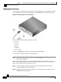
Connecting the Local Console 5-1
Setting Up the Local Console 5-2
Initial System Configuration 5-3
SCE 2000 4xGBE Installation and Configuration Guide
ii
OL-7824-02
Contents
Step 1: Configuring Initial Settings 5-6
Step 2: Configuring the Hostname 5-7
Step 3: Setting the Passwords 5-7
Step 4: Configuring Time Settings 5-8
Step 5: Configuring the DNS Settings 5-10
Step 6: Configuring the RDR Formatter Destination 5-12
Step 7: Configuring Access Control Lists (ACLs) 5-13
Step 8: Configuring SNMP 5-17
Step 9: Configuring the Topology-Dependent Parameters 5-20
Step 10: Completing and Saving the Configuration 5-24
Connecting the Management Interface 5-26
Cabling the Management Port 5-27
Verifying Management Interface Connectivity 5-28
Cabling the Line Ports and Completing the Installation 6-1
Connecting the line ports to the network 6-1
Cabling Diagrams 6-2
Configuring the GBE Interface Parameters 6-7
Connecting the GBE Line Interface Ports 6-8
Testing Connectivity: Examining Link LEDs and Counters 6-10
Installing a Cascaded System 6-12
CLI Commands 6-13
Loading and Activating a Service Control Application 6-16
Basic SCE 2000 Platform Operations 7-1
Starting the SCE 2000 Platform 7-1
Checking Conditions Prior to System Startup 7-1
Starting the System and Observing Initial Conditions 7-2
Final Tests 7-3
Managing SCE 2000 Configurations 7-4
Viewing Configuration 7-4
Saving the Configuration Settings 7-7
Recovering a Previous Configuration 7-9
Performing Complex Configurations 7-10
Rebooting and Shutting Down the SCE Platform 7-11
SCE 2000 4xGBE Installation and Configuration Guide
OL-7824-02
iii
Contents
Rebooting the SCE Platform 7-11
Shutting Down the SCE Platform 7-12
Troubleshooting 8-1
Troubleshooting Overview 8-1
Troubleshooting Tools 8-2
Problem Solving Using a Subsystems Approach 8-9
Identifying Startup Problems 8-9
Troubleshooting the Power Subsystem 8-9
Troubleshooting the Firmware Package Installation 8-11
Troubleshooting the Management Subsystem 8-12
Troubleshooting the Link Interface Subsystem 8-14
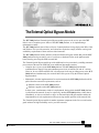
The External Optical Bypass Module A-1
External Optical Bypass Functionality A-2
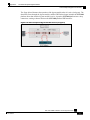
The External Optical Bypass Module Front Panel A-4
Installing the External Bypass Module A-5
Installing the Module in a Rack A-5
Cabling the External Optical Bypass Module A-6
Specifications A-9
Index 1
SCE 2000 4xGBE Installation and Configuration Guide
iv
OL-7824-02
Preface
This preface describes who should read the SCE 2000 4xGBE Installation and Configuration
Guide, how it is organized, and its document conventions
Audience
This guide is for the networking or computer technician responsible for installing and configuring
the SCE 2000 platform on-site. To use this publication, you should be familiar with
telecommunications equipment and installation procedures, as well as electronic circuitry and
wiring practices. You should also have experience as an electronic or electromechanical
technician.
This installation guide explains the initial hardware installation and basic configuration
procedures for the SCE 2000. It contains procedures for unpacking and installing the device and
performing basic configuration via the setup wizard. After completing the installation and basic
configuration procedures covered in this guide, you will then use the appropriate companion
publications to more completely configure your system.
This guide contains instructions on how to install and run the SCE 2000 Platform. This guide
assumes a basic familiarity with telecommunications equipment and installation procedures.
SCE 2000 4xGBE Installation and Configuration Guide
OL-7824-02
v
Preface
Organization
Organization
The major sections of this guide are as follows:
Chapter
Title
Description
1
Introduction (on page 1-1) This chapter provides a brief introduction to Cisco Service
Control.
2
Overview ( on page 2-1)
This chapter provides a hardware overview of the SCE
2000 platform.
3
Topology (on page 3-1)
This chapter describes the possible deployment topologies
of the SCE 2000 and explains how various aspects of the
topology determine the configuration of the system.
4
Installation and
Maintenance (on page 41)
This chapter explains how to install a SCE 2000 platform
in a rack or in a general tabletop installation and how to
install or replace the power supply units and fan modules.
5
Connecting the
This chapter explains how to connect the SCE 2000
Management Interfaces
platform to a local console and perform the initial system
and Performing Initial
configuration via the setup wizard that runs automatically.
System Configuration (on
page 5-1)
6
Cabling the Line Ports
This chapter provides instructions for cabling the Gigabit
and Completing the
Ethernet ports for both one and two SCE 2000 topologies,
Installation (on page 6-1) and for configuring Gigabit Ethernet (GBE) interface
parameters. In a topology utilizing two SCE 2000s
(cascade), this includes the cascade ports as well as the
line ports.
7
Basic SCE 2000 Platform This chapter describes how to start up the SCE 2000
Operations (on page 7-1) platform, reboot, and shutdown. It also describes how to
manage configurations.
8
Troubleshooting (on page This chapter provides basic system startup troubleshooting
8-1)
information.
A
The External Optical
Bypass Module (on page
A-1)
This appendix explains how to install the external optical
bypass module.
SCE 2000 4xGBE Installation and Configuration Guide
vi
OL-7824-02
Preface
Related Publications
Related Publications
Your SCE 2000 platform and the software running on it contain extensive features and
functionality, which are documented in the following resources:
•
Note
Cisco CLI software:
•
Cisco Service Control Engine (SCE) Software Configuration Guide
•
Cisco Service Control Engine (SCE) CLI Command Reference
You can access Cisco software configuration and hardware installation and maintenance documentation
on the World Wide Web at Cisco Website URL http://www.cisco.com. Translated documentation is
available at the following URL: International Cisco Website
(http://www.cisco.com/public/countries_languages.shtml)
•
For initial installation and startup information, refer to the SCE 2000 4xGBE Quick Start Guide.
•
For international agency compliance, safety, and statutory information for wide-area network
(WAN) interfaces for the SCE 2000 platform, refer to the Regulatory Compliance and Safety
Information for the Cisco Service Control Engine (SCE).
•
For installation and configuration of the other components of the Service Control
Management Suite refer to:
•
•
Subscriber Management User Guide
•
Collection Manager User Guide
•
Service Control Application Suite for Broadband User Guide
•
Service Control Application Suite for Broadband Installation Guide
To view Cisco documentation or obtain general information about the documentation, refer to
the following sources:
•
Obtaining Documentation (on page ix)
•
The Cisco Information Packet that shipped with your SCE 2000 platform.
SCE 2000 4xGBE Installation and Configuration Guide
OL-7824-02
vii
Preface
Document Conventions
Document Conventions
Command descriptions use the following conventions:
boldface font
Commands and keywords are in boldface.
italic font
Arguments for which you supply values are in italics.
[]
Elements in square brackets are optional.
{x | y | z}
Alternative keywords are grouped in braces and separated by
vertical bars.
[x | y | z]
Optional alternative keywords are grouped in brackets and separated
by vertical bars.
string
A nonquoted set of characters. Do not use quotation marks around
the string, or the string will include the quotation marks.
Screen examples use the following conventions:
screen font
Terminal sessions and information the system displays are in
screen font.
boldface screen font Information you must enter is in boldface screen font.
italic screen font
Arguments for which you supply values are in italic screen
font.
^
The symbol ^ represents the key labeled Control—for example, the
key combination ^D in a screen display means hold down the
Control key while you press the D key.
<>
Nonprinting characters, such as passwords, are in angle brackets.
[]
Default responses to system prompts are in square brackets.
!, #
An exclamation point (!) or a pound sign (#) at the beginning of a
line of code indicates a comment line.
Notes, cautionary statements, and safety warnings use these conventions.
Note
Warning
Means reader take note. Notes contain helpful suggestions or references to materials not contained in
this manual.
Means reader be careful. You are capable of doing something that might result in equipment damage or
loss of data.
SCE 2000 4xGBE Installation and Configuration Guide
viii
OL-7824-02
Preface
Obtaining Documentation
Obtaining Documentation
Cisco documentation and additional literature are available on Cisco.com http://www.cisco.com.
Cisco also provides several ways to obtain technical assistance and other technical resources.
These sections explain how to obtain technical information from Cisco Systems.
Cisco.com
You can access the most current Cisco documentation at this URL
http://www.cisco.com/univercd/home/home.htm.
You can access the Cisco website at this URL http://www.cisco.com.
You can access international Cisco websites at this URL
(http://www.cisco.com/public/countries_languages.shtml).
Documentation Feedback
You can send comments about technical documentation to this URL (http://[email protected]).
You can submit comments by using the response card (if present) behind the front cover of your
document or by writing to the following address:
Cisco Systems
Attn: Customer Document Ordering
170 West Tasman Drive
San Jose, CA 95134-9883
We appreciate your comments.
Obtaining Technical Assistance
For all customers, partners, resellers, and distributors who hold valid Cisco service contracts, the
Cisco Technical Assistance Center (TAC) provides 24-hour-a-day, award-winning technical
support services, online and over the phone. Cisco.com http://www.cisco.com features the Cisco
TAC website as an online starting point for technical assistance. If you do not hold a valid Cisco
service contract, please contact your reseller.
Cisco Technical Support Website
The Cisco TAC website (http://www.cisco.com/tac) provides online documents and tools for
troubleshooting and resolving technical issues with Cisco products and technologies. The Cisco
TAC website is available 24 hours a day, 365 days a year.
Accessing all the tools on the Cisco TAC website requires a Cisco.com user ID and password. If
you have a valid service contract but do not have a login ID or password, register at this URL
(http://tools.cisco.com/RPF/register/register.do).
SCE 2000 4xGBE Installation and Configuration Guide
OL-7824-02
ix
Preface
Obtaining Additional Publications and Information
Submitting a Service Request
Using the online TAC Service Request Tool (http://www.cisco.com/techsupport/servicerequest) is
the fastest way to open S3 and S4 service requests. (S3 and S4 service requests are those in which
your network is minimally impaired or for which you require product information.) After you
describe your situation, the TAC Service Request Tool automatically provides recommended
solutions. If your issue is not resolved using the recommended resources, your service request will
be assigned to a Cisco TAC engineer.
For S1 or S2 service requests or if you do not have Internet access, contact the Cisco TAC by
telephone. (S1 or S2 service requests are those in which your production network is down or
severely degraded.) Cisco TAC engineers are assigned immediately to S1 and S2 service requests
to help keep your business operations running smoothly.
To open a service request by telephone, use one of the following numbers:
Asia-Pacific: +61 2 8446 7411 (Australia: 1 800 805 227)
EMEA: +32 2 704 55 55
USA: 1 800 553-2447
A complete listing of Cisco TAC contacts (http://www.cisco.com/techsupport/contacts) is
available online.
Definitions of Service Request Severity
To ensure that all cases are reported in a standard format, Cisco has established severity
definitions.
Severity 1 (S1)—Your network is “down” or there is a critical impact to your business operations.
You and Cisco will commit all necessary resources around the clock to resolve the situation.
Severity 2 (S2)—Operation of an existing network is severely degraded, or significant aspects of
your business operation are negatively affected by inadequate performance of Cisco products. You
and Cisco will commit full-time resources during normal business hours to resolve the situation.
Severity 3 (S3)—Operational performance of your network is impaired, but most business
operations remain functional. You and Cisco will commit resources during normal business hours
to restore service to satisfactory levels.
Severity 4 (S4)—You require information or assistance with Cisco product capabilities,
installation, or configuration. There is little or no effect on your business operations.
Obtaining Additional Publications and Information
Information about Cisco products, technologies, and network solutions is available from various
online and printed sources.
•
Cisco Marketplace (http://www.cisco.com/go/marketplace/) provides a variety of Cisco
books, reference guides, and logo merchandise.
•
The Cisco Product Catalog describes the networking products offered by Cisco Systems, as
well as ordering and customer support services.
SCE 2000 4xGBE Installation and Configuration Guide
x
OL-7824-02
Preface
Obtaining Additional Publications and Information
•
Cisco Press (http://www.ciscopress.com) publishes a wide range of general networking,
training and certification titles. Both new and experienced users will benefit from these
publications. For current Cisco Press titles and other information, go to Cisco Press
(http://www.ciscopress.com).
•
Packet (http://www.cisco.com/packet) magazine is the Cisco Systems technical user magazine
for maximizing Internet and networking investments. Each quarter, Packet delivers coverage
of the latest industry trends, technology breakthroughs, and Cisco products and solutions, as
well as network deployment and troubleshooting tips, configuration examples, customer case
studies, certification and training information, and links to scores of in-depth online resources.
•
iQ Magazine (http://www.cisco.com/go/iqmagazine) is the quarterly publication from Cisco
Systems designed to help growing companies learn how they can use technology to increase
revenue, streamline their business, and expand services. The publication identifies the
challenges facing these companies and the technologies to help solve them, using real-world
case studies and business strategies to help readers make sound technology investment
decisions.
•
Internet Protocol Journal (http://www.cisco.com/ipj) is a quarterly journal published by Cisco
Systems for engineering professionals involved in designing, developing, and operating public
and private internets and intranets.
•
World-class networking training is available from Cisco. You can view current offerings at
this URL (http://www.cisco.com/en/US/learning/index.html).
SCE 2000 4xGBE Installation and Configuration Guide
OL-7824-02
xi
CHAPTER 1
Introduction
This chapter contains the following sections:
• SCE Platform Management Interfaces
1-2
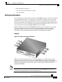
The Service Control Engine family of programmable network devices is capable of performing
stateful flow inspection of IP traffic, and controlling that traffic based on configurable rules. The
Service Control Engine platforms provide a real-time classification of network usage through
programmable, stateful inspection of bi-directional traffic flows and the mapping of these flows
with user ownership.
The following diagram demonstrates a deployment of an SCE 2000 platform in the network.
Figure 1-1: SCE Platform in the Network
SCE 2000 4xGBE Installation and Configuration Guide
OL-7824-02
1-1
Chapter 1
Introduction
SCE Platform Management Interfaces
SCE Platform Management Interfaces
You can manage the SCE 2000 platform through either of its management interfaces, CLI or
SNMP. Both these interfaces provide management access to the same database of the SCE 2000
platform; any configuration changes made through one interface are also reflected through the
other interface.
•
CLI (Command Line Interface). The CLI is accessible through the Console port or through a
Telnet connection. The CLI is the interface described throughout this manual. Command Line
Interface further discusses the CLI.
•
SNMP (Simple Network Management Protocol). You can use SNMP as an interface for
monitoring the variables as defined in the MIB-II and Cisco’s propriety MIB specifications.
For information on enabling SNMP, see SNMP Interface
SCE 2000 4xGBE Installation and Configuration Guide
1-2
OL-7824-02
CHAPTER 2
Overview of the SCE 2000 Platform
This chapter provides a brief overview of the Cisco Service Control concept and an introduction
to the SCE 2000 4xGBE Platform, the Service Control hardware component.
This chapter contains the following sections:
• Service Control and the SCE Platform
2-1
• Front Panel2-3
• Back Panel 2-6
• Checking the Shipping Container Contents
• SCE 2000 Installation Checklist
2-7
2-8
Service Control and the SCE Platform
The Cisco Service Control concept is delivered through a combination of purpose-built hardware
and specific software solutions that address various Service Control challenges faced by service
providers.
The SCE Platform
The Service Control Engine (SCE) platform, which is the hardware component of the Cisco
Service Control solution, is designed to support observation, analysis, and control of Internet/IP
traffic. The SCE platform is a purpose-built network device making use of ASIC components and
RISC processors to go beyond packet counting and delve deeper into the contents of network
traffic to do the following:
•
Provide programmable, stateful inspection of bi-direction traffic flows
•
Map these flows with user ownership
•
Provide a real-time classification of network usage, which is the basis of the SCE platform
advanced traffic control and bandwidth shaping functionality.
SCE 2000 4xGBE Installation and Configuration Guide
OL-7824-02
2-1
Chapter 2
Overview of the SCE 2000 Platform
Service Control and the SCE Platform
Table 2-1
SCE Platform Model Information
Model number
SCE 2020 4xGBE
Link Type
Gigabit Ethernet
Number of Ports
4
Number of Links
2
Service Control Management
The Service Control solution includes a complete management infrastructure that provides the
following management components to manage all aspects of the Service Control solutions:
•
Network management: complete network FCAPS Management (Fault, Configuration,
Accounting, Performance, Security) is provided via either CLI or SNMP.
•
Subscriber management: subscriber awareness (mapping network IDs to subscriber IDs) and
integration with AAA devices such as Radius or DHCP servers is provided by the Subscriber
Manager (SM).
•
Service Configuration Management: ability to configure the general service definitions of a
Service Control application via an XML configuration file.
These management interfaces are designed to comply with common management standards and to
easily integrate with existing OSS infrastructure.
Figure 2-1: Service Control Management Infrastructure
SCE 2000 4xGBE Installation and Configuration Guide
2-2
OL-7824-02
Chapter 2
Overview of the SCE 2000 Platform
Front Panel
Front Panel
The SCE 2000 Front Panel consists of ports and LEDs as shown in the following figure and
tables.
Figure 2-2: SE2000 Front Panel
SCE 2000 4xGBE Installation and Configuration Guide
OL-7824-02
2-3
Chapter 2
Overview of the SCE 2000 Platform
Front Panel
Table 2-2
SCE 2000 Ports
Port
Quantity
Description
Connect This Port To…
Mng1/
Mng2
2
10/100/1000 Ethernet RJ-45 ports for
management of the SCE 2000.
A LAN using an FE cable
with an RJ-45 connector
Mng 2 is currently not operational.
CLI designation: 0/0.
Console
1
RS-232 RJ-45 port for use by
technicians
AUX
1
RS-232 RJ-45 port used by technicians
GBE ports 14
4
GigabitEthernet SC ports for connecting
to the line and/or cascading two devices
CLI designation: 0/1 through 0/4
Table 2-3
A local terminal (console)
using an RS-232 cable with
an RJ-45 connector, as
provided in the SCE 2000
kit.
Refer to Connecting the Line
Ports (Connecting the Line
Ports "Connecting the line
ports to the network" on
page 6-1) for cabling
diagrams for various
topologies
SCE 2000 LED Groups
LED Groups
Description
Power A
• Continuous green: Power supply A is functioning normally
• Red: Power supply A present, but malfunctioning
• Unlit: Power supply A is either not present or has failed.
Power B
• Continuous green: Power supply B is functioning normally
• Red: Power supply B present, but malfunctioning
• Unlit: Power supply B is either not present or has failed.
Status
The Status LED indicates the operational status of the SCE 2000 system, as
follows:
• Unlit: indicates no power from either power unit.
• Orange: indicates that the system is booting up.
• Flashing green: indicates that the system is fully operational.
• Flashing orange: indicates that the system is operational, but is in a warning
state.
• Red: indicates that there is a problem or failure
Note that Alarms are hierarchical: Failure takes precedence over Warning, which
takes precedence over operational.
SCE 2000 4xGBE Installation and Configuration Guide
2-4
OL-7824-02
Chapter 2
Overview of the SCE 2000 Platform
Front Panel
LED Groups
Description
Bypass
• Continuous green: indicates that the traffic bypasses the SCE 2000 through an
internal electrical bypass module.
Single SCE 2000 topology: The SCE 2000 is either in bypass or sniffing mode
Cascaded topology: Either the SCE 2000 is forwarding traffic to the other SCE
2000, where it is being processed, or is simply in bypass mode, so traffic
through it is not being processed.
• Unlit: traffic is not being bypassed
Single SCE 2000 topology: indicates normal operation of the SCE 2000
Cascaded topology: indicates normal operation of the active SCE 2000
GBE ports
The GBE LEDs indicate the operational status of the SCE 2000 line ports, as
follows:
• Link
Green: indicates that the port link is up
Unlit: indicates that the port link is down
• Rx
Flashing Green: indicates that there are incoming packets
• Tx
Flashing Green: indicates that there are outgoing packets
Mng
The Mng port LEDs indicate the operational status of the SCE 2000 out-of-band
LAN-based management port, as follows:
• Link/Active
Green: indicates that the port link is up
Unlit: indicates that the port link is down
• 10/100/1000
Steady green: indicates that the port is set to 100 Mbps
Unlit: indicates that the port is set to 10 Mbps
Orange: indicates that the port is set to 1000 Mbps
SCE 2000 4xGBE Installation and Configuration Guide
OL-7824-02
2-5
Chapter 2
Overview of the SCE 2000 Platform
Back Panel
Back Panel
The SCE 2000 platform back-panel contains the following components:
•
Two field-replaceable power supply units with ON/OFF switches
•
A field-replaceable fan drawer
•
Ground connections
•
Two connectors to the external bypass module
The rear panels of both the AC- and DC-powered SCE 2000 platforms are shown in the following
pair of figures.
Figure 2-3: SCE 2000 Back Panel: AC Power
Figure 2-4: SCE 2000 Back Panel DC power
SCE 2000 4xGBE Installation and Configuration Guide
2-6
OL-7824-02
Chapter 2
Overview of the SCE 2000 Platform
Checking the Shipping Container Contents
Checking the Shipping Container Contents
Use the SCE 2000 Components List to check the contents of the SCE 2000 platform shipping
container.
Do not discard the shipping container. You need the container if you move or ship the SCE 2000
platform in the future.
SCE 2000 Component List
Table 2-4
SCE 2000 Component List
Component
Description
Received
SCE 2000 platform
SCE 2020 4xGBE platform configured with either AC or
DC power supplies.
Accessories
The following accessories might arrive in separate shipping
containers:
• Rack mount kit
• Two mounting brackets for 19” rack
• Six screws (Philips), 8-32 x 3/8” (for attaching the
brackets to the SCE 2000 chassis)
• supporting mounting brackets for 19” rack
• Two crossrail supports for 19” rack with front and back
posts
• Management
cables
• Fast Ethernet cable for connecting to the Management
port
• RS-232 serial cable (DB-9 to RJ-45) for connecting to a
local terminal
• Power cables
Two AC power supply cords,if ordered with AC-input
power supply units
• Grounding kit
• Grounding cable
• Two Hex nuts (#¼”)
• Two spring washers (#¼”)
• Documentation
If ordered, SCE 2000 hardware and software
documentation set and the Cisco Documentation CD-ROM
package*
Optional Equipment Four rubber feet for tabletop installation
External Optical
Bypass module kit
• 1 External Optical Bypass module
• 1 19" rack mounting panel
• 1 control cable
*Titles and quantities of documents will vary. You must order the type and quantity of documentation
sets when you order the hardware.
SCE 2000 4xGBE Installation and Configuration Guide
OL-7824-02
2-7
Chapter 2
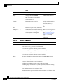
Note
Overview of the SCE 2000 Platform
We no longer ship the entire SCE 2000 documentation set automatically with each system. You must
specifically order the documentation as part of the sales order. If you ordered documentation and did
not receive it, we will ship the documents to you within 24 hours. To order documents, contact a
customer service representative.
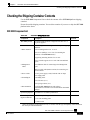
SCE 2000 Installation Checklist
To assist you with your installation and to provide a historical record of what was done by whom,
photocopy the following SCE 2000 Installation Checklist. Indicate when each procedure or
verification is completed. When the checklist is completed, place it in your site log along with the
other records for your new SCE 2000 platform.
SCE 2000 4xGBE Installation and Configuration Guide
2-8
OL-7824-02
Chapter 2
Overview of the SCE 2000 Platform
SCE 2000 Installation Checklist
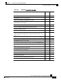
Table 2-5
SCE 2000 Installation Checklist
Task
Verified
By
Date
Date SCE 2000 received
SCE 2000 and all accessories unpacked
Safety recommendations and guidelines reviewed
Topology verified: number of SCE 2000 platforms, number of links, and
whether inline or receive-only
Installation Checklist copied
Site log established and background information entered
Site power voltages verified
Site environmental specifications verified
Required passwords, IP addresses, device names, and so on, needed for
initial configuration available (refer to Setup Command Parameters (on
page 5-3))
Required tools available
Network connection equipment available
SCE 2000 mounted in rack (optional)
AC/DC power cables connected to AC/DC sources and SCE 2000 platform
Console port set for 9600 baud, 8 data bits, no parity, and 1 stop bit (9600
8N1)
ASCII terminal attached to console port
FE management port is operational
GBE line and cascade ports operational
Network interface cables and devices connected
System power turned on
System boot complete (SYSTEM–UP LED is on)
Correct hardware configuration displayed after system banner appears
SCE 2000 4xGBE Installation and Configuration Guide
OL-7824-02
2-9
CHAPTER 3
Topology
This chapter describes the possible deployment topologies of the SCE 2000. The Cisco SCE
solution offers a number of basic topology options that permit the user to tailor the SCE Platform
to fit the needs of a particular installation. An understanding of the various issues and options is
crucial to designing, deploying, and configuring the topology that best meets the requirements of
the individual system.
This chapter contains the following sections:
• The SCE 2000 Platform
3-1
• Topology Considerations 3-1
• Physical Topologies
3-4
The SCE 2000 Platform
The SCE 2000 introduces a solution for dual links with load sharing and asymmetrical routing
and support for fail-over between two SCE platforms.
The SCE 2000 supports wire speed processing of full-duplex 2-Gigabit Ethernet streams. The
SCE 2000 can, therefore, be deployed in a multi-link environment, either in a single or dual SCE
platform topology.
•
single SCE 2000 topology: Provides increased network capacity and the ability to process
both directions of a bi-directional flow, processing both the upstream and downstream paths
of a flow, even if they traverse different links
•
dual SCE 2000 topology (cascade): cascaded SCE 2000s provide high-availability and failover solution and maintain the line and service in case of SCE 2000 failure.
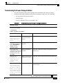
Topology Considerations
There are several issues that must be considered in order to arrive at the optimum configuration of
the topology-related parameters:
•
Functionality: Will the system be used solely to monitor traffic flow, with report functionality
only, or will it be used for traffic flow control, with enforcement as well as report
functionality?
SCE 2000 4xGBE Installation and Configuration Guide
OL-7824-02
3-1
Chapter 3
Topology
Topology Considerations
•
Number of links: The SCE 2000 may be connected to one or two GBE links. This is relevant
for both bump-in-the-wire and Receive-Only topologies.
•
Redundancy: Must the system be designed to guarantee uninterrupted SCE 2000
functionality? If so, there must be a backup SCE 2000 Platform to assume operation in case of
failure of the primary device.
•
Link continuity: How should the SCE 2000 respond to platform failure with regard to link
continuity? Should traffic flow continue even though the unit is not operating, or be halted
until the platform is repaired/replaced?
These issues determine three important aspects of system deployment and configuration:
•
How many SCE 2000 Platforms are needed and how will they be installed?
•
Physical topology of the system: The actual physical placement of the SCE 2000 in the
system.
•
Topology-related configuration parameters: The correct values for each parameter must be
ascertained before configuring the system to make sure that the system will function in the
desired manner.
Functionality
The SCE 2000 can serve one of two general functions:
•
Monitoring and Control: The SCE 2000 monitors and controls traffic flow. Decisions are
enforced by the SCE 2000 depending on the results of the monitoring functions of the SCE
2000 and the configuration of the Service Control Application for Broadband or Mobile
solution.
In order to perform control functions, the SCE 2000 must be physically installed as a bumpin-the-wire, and the connection mode must be “Inline”.
•
Monitoring only: The SCE 2000 monitors traffic flow, but cannot control it.
Either a bump-in-the-wire installation or an optical splitter installation may be used for
monitoring only. In the latter case connection mode must be “receive-only”.
Number of links
The SCE 2000 can be deployed in a single GBE link or in two GBE links. The two-link topology
may implement load-sharing and the SCE 2000 in this case is able to process both directions of a
bi-directional flow even if they split to both links.
Redundancy
When a high degree of reliability is desired, a second SCE 2000 Platform should be installed to
provide backup operation capabilities. The combination of two SCE 2000s guarantees
uninterrupted functioning in case of a failure of one of the platforms. The two SCE 2000s are
cascaded, so that, although all processing is performed only in the active SCE 2000, the standby
SCE 2000 is constantly updated with all the necessary information so that it can instantly take
over processing the traffic on the data links should the active SCE 2000 fail.
If only preservation of the network links is required, and uninterrupted functionality of the SCE
2000 is not required, a single SCE 2000 is sufficient.
SCE 2000 4xGBE Installation and Configuration Guide
3-2
OL-7824-02
Chapter 3
Topology
Topology Considerations
Link Continuity
The bypass mechanism of the SCE 2000 allows traffic to continue to flow, if desired, even if the
device itself is not functioning.
Note that when the SCE 2000 is connected to the network through an optical splitter, a failure of
the SCE 2000 does not affect the traffic flow, as the traffic continues to flow through the optical
splitter.
Bypass Mechanism
The SCE 2000 includes a Network Interface Card with a bypass mechanism that is enabled upon
SCE 2000 failure. In addition, when connected in-line it can also be enabled in normal operation
to simultaneously bypass traffic flow to the other side and direct it internally for analysis. In this
case it maintains "receive-only"-like monitoring functions, when control functionality is not
required.
The bypass card supports the following four modes:
•
Bypass: The bypass mechanism preserves the network link, but traffic is not processed for
monitoring or for control.
•
Forwarding: This is the normal operational mode, in which the SCE 2000 processes the
traffic for monitoring and control purposes.
•
Sniffing: The bypass mechanism preserves the network link, while in parallel allowing the
SCE 2000 to process the traffic for monitoring only.
•
Cutoff: There is no forwarding of traffic, and the physical link is forced down (cutoff
functionality at layer 1).
Maintaining the Network Links vs Maintaining SCE 2000 Platform
Functionality
When a single SCE 2000 is deployed, the user may decide that in case of a failure, maintaining
the network link is more important than providing the SCE 2000 functionality. In this scenario,
when the SCE 2000 detects a failure that requires a reboot process for recovering, it immediately
switches to Bypass mode, allowing all traffic to bypass the SCE 2000. The SCE 2000 stays in
Bypass mode maintaining the network link, albeit without SCE 2000 processing, until the SCE
2000 fully recovers from the failure and is ready to resume normal functioning.
Alternatively, the user may decide that the SCE 2000 functionality is sufficiently crucial to
require severing the link if the SCE 2000 platform fails. In this case, when the SCE 2000 detects a
failure that requires a reboot process for recovering, it immediately switches to Cutoff mode,
stopping all traffic flow. The SCE 2000 stays in Cutoff mode, halting all traffic, until it fully
recovers from the failure and is ready to resume normal functioning. In Cutoff the physical
interface is blocked, enabling the network device connected to the SCE 2000 to sense that the link
is down.
SCE 2000 4xGBE Installation and Configuration Guide
OL-7824-02
3-3
Chapter 3
Topology
Physical Topologies
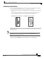
Single Link: Receive-only Topology
In this topology, an optical splitter resides physically on the GBE link between the subscribers and
the network. The traffic passes through the optical splitter, which splits traffic to the SCE 2000.
The SCE 2000, therefore, only receives traffic and does not transmit.
Figure 3-1: Single SCE Platform Single Link: Receive-Only Topology
When configuring the SCE 2000, an optical splitter topology is referred to as “receive-only”
connection mode.
Note that in an optical splitter topology, the SCE 2000 only enables traffic monitoring
functionality.
Note
When implementing receive-only topologies with a switch, the switch must support SPAN functionality
that includes separation between ingress and egress traffic and multiple SPAN-ports destinations.
Physical Topologies
Following are descriptions of a number of physical topologies that the SCE 2000 supports.
Single SCE 2000 Topologies
A single SCE 2000 supports both single GBE link and dual GBE link topologies.
SCE 2000 4xGBE Installation and Configuration Guide
3-4
OL-7824-02
Chapter 3
Topology
Physical Topologies
Single Link: Inline Topology
Typically, the SCE 2000 is connected in a full duplex GBE link between two devices (Router,
BRAS, etc.). When the SCE 2000 is installed as a bump-in-the-wire, it physically resides on the
data link between the subscribers and the network.
Figure 3-2: Single SCE Platform Single Link: In-line Topology
When configuring the SCE 2000, a bump-in-the-wire installation is referred to as “inline”
connection mode.
Dual link: Inline Installation
In this topology, one SCE 2000 is connected inline in two full duplex, GBE links.
In case the two links are load-shared, asymmetrical routing might occur, and some of the flows
may be split, i.e. the upstream packets of the flow go on one link, and the downstream packets go
on the other link.
When installed in this topology, the SCE 2000 completely overcomes this phenomenon, and
provides its normal functionality as if asymmetrical routing were not occurring in the two links.
Figure 3-3: Single SCE Platform Dual Link Inline Topology
This topology supports both monitoring and control functionality, and is referred to as “inline”
connection mode.
SCE 2000 4xGBE Installation and Configuration Guide
OL-7824-02
3-5
Chapter 3
Topology
Physical Topologies
Dual Link: Receive-Only Topology
In this topology, one SCE 2000 is connected in receive-only mode to two full duplex, GBE links
using optical splitters. If the two links are load-shared, asymmetrical routing might occur, and
some of the flows may be split, i.e. the upstream packets of the flow go on one link, and the
downstream packets go on the other link.
When installed in this topology, the SCE 2000 completely overcomes this phenomenon, and
provides its normal monitoring functionality as if asymmetrical routing were not occurring in the
two links.
This installation supports monitoring functionality only, and is configured as “receive-only”
connection mode.
Figure 3-4: Single SCE Platform Dual Link Receive-Only Topology
Note
When implementing receive-only topologies with a switch, the switch must support SPAN functionality
that includes separation between ingress and egress traffic and multiple SPAN-ports destinations.
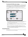
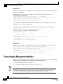
Two Cascaded SCE 2000s For Dual Links
In this topology, two cascaded SCE 2000s are used. This allows a fail-over solution, where in case
of a failure of one SCE 2000, the functionality that the SCE 2000 provides is preserved by the
redundant platform.
SCE 2000 4xGBE Installation and Configuration Guide
3-6
OL-7824-02
Chapter 3
Topology
Physical Topologies
Two Cascaded SCE 2000s: Inline Topology
This topology allows both control and monitoring functionality where redundancy is required and
“inline” connection is used. The two SCE 2000s are cascaded, so the primary SCE 2000 process
the traffic of the two links, while the secondary SCE 2000 only bypasses the traffic of its links to
the primary SCE 2000 for processing, and then bypasses the processed traffic back to the link.
The two SCE 2000s also exchange keep-alive messages and subscriber state information.
In case the primary SCE 2000 fails, the two SCE 2000s switch their roles, and this way fail-over
is provided.
Figure 3-5: Two SCE Platforms: Dual Link Inline Topology
This fail-over solution preserves the SCE 2000 functionality and the network link:
•
The two SCE 2000s are simultaneously aware of the subscriber contexts, and subscriber states
are constantly exchanged between them, such that if the primary SCE 2000 fails, the
secondary can take over with minimum state loss.
•
When one SCE 2000 fails (depending on the type of failure) its link traffic is still bypassed to
the functioning SCE 2000 and processed there, so the traffic processing continues for both the
links.
•
The bypass of the traffic through the failed SCE 2000 is configurable, and the user may
choose to always cutoff the line that goes through the failed SCE 2000. In this case network
redundancy protocols like HSRP are responsible for identifying the line cutoff and switching
all the traffic to go through the functioning SCE 2000.
Topology-Related Parameters
Refer to the following sections to determine the correct values for all topology-related parameters
before beginning run the initial setup of the SCE 2000.
SCE 2000 4xGBE Installation and Configuration Guide
OL-7824-02
3-7
Chapter 3
Topology
Physical Topologies
SCE 2000 Configuration
There are four topology-related parameters:
•
•
Connection mode: Can be any one of the following, depending on the physical installation of
the SCE 2000:
•
Inline: single SCE 2000 inline
•
Receive-only: single SCE 2000 receive-only
•
Inline-cascade: two SCE 2000s inline
•
Receive-only-cascade: two SCE 2000s receive-only
Physically-connected-links: In cascaded configurations, this parameter defines the number of
the link connected to this SCE 2000.
It is applicable only in a cascade topology.
•
Priority: This parameter defines which SCE 2000 platform is the primary device.
It is applicable only in a cascade topology.
•
On-failure: This parameter determines whether the system cuts the traffic or bypasses it when
the SCE 2000 either has failed or is booting. It is not applicable to receive-only topologies.
Any of these parameters may be configured via either the setup command or the
connection-mode command.
Connection Mode Parameter
The connection mode parameter refers directly to the physical topology in which the SCE 2000 is
installed. The connection mode depends on two factors:
•
•
Inline/Receive-only:
•
Inline: The SCE 2000 resides on the data link between the subscriber side and the
network side, thus both receiving and transmitting packets.
•
Receive-only: The SCE 2000 does not reside physically on the data link. Data is
forwarded to the SCE 2000 via an external switch. The SCE 2000 itself receives only and
does not transmit.
Cascade: Indicates a two SCE 2000 topology where the SCE 2000 platforms are connected
via the cascade ports.
The connection mode parameter is determined by the physical deployment of the SCE 2000, as
follows:
•
Single SCE 2000 bump-in-the-wire installation = “Inline” connection mode.
•
Single SCE 2000 optical splitter installation = “Receive-only” connection mode.
•
Two SCE 2000 bump-in-the-wire installation = “Inline-cascade” connection mode.
•
Two SCE 2000 optical splitter installation = “Receive-only-cascade” connection mode.
SCE 2000 4xGBE Installation and Configuration Guide
3-8
OL-7824-02
Chapter 3
Topology
Physical Topologies
Physically Connected Links Parameter
If the system consists of more than one device, this parameter defines which link is connected to
this SCE 2000. Currently the system supports a maximum of two links, which are designated link
0 and link 1.
Priority
In a cascade topology, the user must define the priority of each SCE 2000.
•
Primary: The Primary SCE 2000 is active by default
•
Secondary: The Secondary SCE 2000 is the default standby.
Note that these defaults apply only when both devices are started together. However, if the
primary SCE 2000 fails and then recovers, it will not revert to active status, but remains in
standby status, while the secondary device remains active.
On-Failure Mode Parameter
As described in the section The Bypass Mechanism, the bypass card supports four different
modes. The following two modes are possible when the SCE 2000 is not operational due to
platform failure or boot:
•
Bypass: The optical splitter forwards traffic with no intervention of the control application
running in the SCE 2000 platform, but monitoring functions continue uninterrupted.
•
Cutoff: There is no forwarding of traffic. The link is forced down, resulting in traffic cutoff at
Layer1.
The Forwarding mode enables control of traffic flow and is not compatible with the nonoperational status.
In a single SCE 2000 topology, the value of this parameter is determined by whether or not the
link can be completely cut when the SCE 2000 fails, or whether traffic flow should continue
across the link in spite of platform failure.
•
•
Cutoff mode is required for the following:
•
Redundant bump-in-the-wire topology.
•
Non-redundant bump-in-the-wire topology if value-added services are crucial and are
more important than maintaining connectivity.
Bypass mode is required for the following:
•
Non-redundant bump-in-the-wire topology if connectivity is crucial.
SCE 2000 4xGBE Installation and Configuration Guide
OL-7824-02
3-9
CHAPTER 4
Installation and Maintenance
This chapter explains how to install a SCE 2000 platform in a rack or in a general tabletop or
workbench installation. Additionally, this chapter contains instructions for installing or replacing
the power supply units and fan modules.
Warning
Before you install, operate, or service the system, read the Site Preparation and Safety Guide. This
guide contains important safety information you should know before working with the system.
This chapter contains the following sections:
• Preparing to Install the SCE 2000 Platform
4-1
• Installing the SCE 2000 Platform 4-4
• Power Supply Overview 4-16
• Removing and Replacing a Power Supply Unit
• Fan Module Overview
4-25
• Replacing the Battery
4-28
4-19
Preparing to Install the SCE 2000 Platform
Before installing your SCE 2000 platform, you should consider the power and cabling
requirements that must be in place at your installation site, the equipment you need to install the
platform, and the environmental conditions your installation site must meet to maintain normal
operation. This section guides you through the process of preparing for your SCE 2000 platform
installation and the installation in a rack. The section contains the following topics:
•
Tools and Parts Required (on page 4-2)
•
Site Requirement Guidelines (on page 4-3)
SCE 2000 4xGBE Installation and Configuration Guide
OL-7824-02
4-1
Chapter 4
Installation and Maintenance
Preparing to Install the SCE 2000 Platform
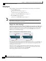
Figure 4-1: SCE 2000 Measurements
Table 4-1
SCE 2000 Dimensions
Dimension
Measurement
Height
3.47 inches (9.5 cm)
Width
17.4 inches (4.43 cm)
Depth
18 inches (4.6 cm)
Weight
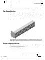
33 lb (15 kg)
Tools and Parts Required
The SCE 2000 chassis is fully assembled at the factory, including the application and software
packages. No assembly is required. However, you need the following tools and equipment to
install the SCE 2000 chassis and the rack-mount kit (if installing the SCE 2000 platform in a
rack), fan modules, and power supplies:
•
Number 1 and 2 Phillips screwdriver
•
1/4 inch flat-blade screwdriver
•
#¼” Hex Wrench
•
Screws compatible with your rack (for mounting the SCE 2000 to the rack)
•
12 AWG or 2.5-mm copper installation wire with hex or loop connectors for DC power leads
Ring terminals must be UL approved and suitable for 12 AWG wire.
•
Level (optional)
•
Tape measure (optional)
•
Appropriate cables to connect the SCE 2000 to the network and console terminal
SCE 2000 4xGBE Installation and Configuration Guide
4-2
OL-7824-02
Chapter 4
Installation and Maintenance
Preparing to Install the SCE 2000 Platform
•
Rack-mounting kit (optional)
•
A new AC-input or DC-input power supply
•
A new fan module
Site Requirement Guidelines
The environmental monitoring functionality in the SCE 2000 protects the system and components
from potential damage from over-voltage and over-temperature conditions. To ensure normal
operation and to avoid unnecessary maintenance, plan your site configuration and prepare your
site before installation. After installation, make sure the site maintains an ambient temperature of
41°F to 104°F (5°C to 40°C) with short term temperatures ranging from 23°F to 131°F (–5°C to
55°C), and keep the area around the SCE 2000 chassis free from dust.
Planning a proper location for the SCE 2000 and the layout of your equipment rack or wiring
closet is essential for successful system operation. Equipment placed too close together or
inadequately ventilated can cause system over-heating. In addition, chassis panels made
inaccessible by poor equipment placement can make system maintenance difficult.
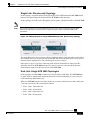
Airflow
Figure 4-2: Airflow Through the SCE 2000
When you plan the location and layout of your equipment rack or wiring closet you need to
consider how air flows though your system. The SCE 2000 draws cooling air in through the
intake vents on the left side of the chassis, moves the air across the internal components, and out
through the right side and rear panel of the chassis. The above figure illustrates the airflow
through the SCE 2000.
Note
Remember to leave a two inch (5 cm) clearance on both sides of the SCE 2000 and five inches (12.7
cm) at the rear for adequate airflow for the inlet and exhaust vents.
SCE 2000 4xGBE Installation and Configuration Guide
OL-7824-02
4-3
Chapter 4
Installation and Maintenance
Installing the SCE 2000 Platform
Site Requirements
The following tables contain the site requirement specifications for the SCE 2000.
Table 4-2
SCE 2000 Environmental Requirements
Specification
Acceptable Range
Temperature -
nominal 41°F to 104°F (5°C to 40°C)
Short term temperatures*
23°F to 131°F (-5°C to +55°C)
Relative humidity
5% to 95% (non-condensing)
Heat dissipation
683 BTU/hour
*Short term is defined as not more than 96 consecutive hours, not more than 15 days in one year.
360 hours total in any given year, but no more than 15 occurrences in a one-year period.
Table 4-3
SCE 2000 Approvals Specifications
Approval
Specification
EMC
• CE Mark
• EMISSIONS: FCC Part 15 CFR 47 Class A, EN 55022 Class A, CISPR22
Class A, VCCI Class A, AS/NZS CISPR22 Class A
• Immunity - EN 50082-1 EN 55024, CISPR24 (ESD, RFI, EFT, etc.)
(Commercial)
Safety
UL/CSA 60950, IEC60950, EN60950, AS/NZS, 60950, NOM019,IEC/EN60825-1, -2, 21CFR1040, 73/23/ECC
For more complete information regarding safety and regulatory compliance, refer to the
Regulatory Compliance and Safety Information for the Cisco Service Control Engine document.
Warning
The DC-powered SCE 2000 should be installed in a Restricted Access Location only.
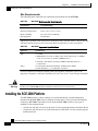
Installing the SCE 2000 Platform
The SCE 2000 operates as either a tabletop or a rack-mounted unit. A rack-mounting kit is
included with the SCE 2000 when it is shipped from the factory. The kit provides the hardware
needed (see SCE 2000 Components List) to mount the SCE 2000 in either of two types of
standard 19-inch equipment rack:
•
19-inch rack with only two posts in the front: Use the supporting brackets included in the kit
•
19-inch rack with four posts, two in the front and two in the back: Use the crossrail supports
included in the kit
SCE 2000 4xGBE Installation and Configuration Guide
4-4
OL-7824-02
Chapter 4
Installation and Maintenance
Installing the SCE 2000 Platform
If you are not rack-mounting your SCE 2000, place it on a sturdy tabletop or workbench. A rubber
feet kit is included for tabletop installations.
This section provides instructions for the physical installation of the SCE 2000 platform,
including how to install the SCE 2000 in a rack, how to install the SCE 2000 on a tabletop or
workbench, and how to properly ground the SCE 2000 platform. The section contains the
following topics:
•
Installation Precautions (on page 4-5)
•
Installing the SCE 2000 on a Workbench or Tabletop (on page 4-6)
•
Rack-Mounting a SCE 2000 Platform ("Rack-Mounting a SCE 2000 Platform" on page 4-7)
•
Attaching a Chassis Ground Connection (on page 4-13)
Installation Precautions
The router should already be in the area where you will install it, and your installation location
should already be determined. If not, see Site Requirement Guidelines (on page 4-3) and the Site
Preparation and Safety Guide.
When installing the SCE 2000, please observe the following conditions:
•
Allow at least 2 inches (5 cm) of clearance at its left and right sides for airflow clearance from
the inlet and exhaust vents, and that no exhaust air from other equipment is drawn into the
SCE 2000. For descriptions and illustrations regarding air flow, see Airflow (on page 4-3).
•
Do not place the SCE 2000 on the floor during installation. Dust that accumulates on the floor
is drawn into the interior of the SCE 2000 by the cooling fans. Excessive dust inside the SCE
2000 can cause over-temperature conditions and component failures.
•
Allow at least 5 inches (12.7 cm) of clearance at the front and rear of the SCE 2000 for
installing and rudimentary maintenance for accessing network cables or equipment.
•
Ensure that the SCE 2000 will receive adequate ventilation. Do not install the SCE 2000 in an
enclosed cabinet where ventilation is inadequate!
•
Provide an adequate chassis Ground (earth) connection for the SCE 2000 (see Attaching a
Chassis Ground Connection (on page 4-13) for instructions).
SCE 2000 4xGBE Installation and Configuration Guide
OL-7824-02
4-5
Chapter 4
Installation and Maintenance
Installing the SCE 2000 Platform
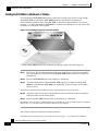
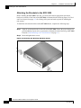
Installing the SCE 2000 on a Workbench or Tabletop
You can install the SCE 2000 platform on any flat surface as long as the surface is large enough
for the SCE 2000 (see the table in SCE 2000 Dimensions), and allows for adequate air
flow/ventilation around the sides of the SCE 2000, as described in the Installation Precautions
(on page 4-5)). When installing the SCE 2000 on a workbench or tabletop or in a rack, ensure that
the surface is clean and in a safe location.
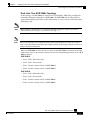
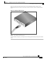
Figure 4-3: Installing the System on a Flat Surface
To install a SCE 2000 platform on a workbench or tabletop, complete the following steps:
Step 1 Remove any debris and dust from the tabletop or workbench, as well as the surrounding
area. Also make sure your path between the SCE 2000 platform and its new location is
unobstructed.
Step 2 Place the SCE 2000 platform on the tabletop or workbench.
Step 3 View the bottom panel by lifting the SCE 2000, placing your hands around the SCE
2000 sides and lifting the SCE 2000 from underneath. To prevent injury, avoid sudden
twists or moves.
There are four marked locations, indicating where to affix the rubber feet (see figure above).
Step 4 Attach the rubber feet by removing the adhesive strips and affix the rubber feet onto the
marked locations (on the bottom panel).
Step 5 Replace the SCE 2000 platform firmly on the tabletop or workbench.
Remember to check for proper ventilation. Allow at least 2 inches (5 cm) on each side for proper ventilation
and 5 inches (12.7 cm) at the back for ventilation and power cord clearance.
This completes the general workbench or tabletop installation.
Proceed to section, Attaching a Chassis Ground Connection (on page 4-13) to continue the installation.
SCE 2000 4xGBE Installation and Configuration Guide
4-6
OL-7824-02
Chapter 4
Installation and Maintenance
Installing the SCE 2000 Platform
Rack-Mounting a SCE 2000 Platform
You can mount the SCE 2000 platform to a 19” rack. There are two standard types of equipment
racks, and the appropriate brackets for each are provided in the enclosed kit.
•
19” rack with front rack posts: the mounting kit includes two mounting brackets as illustrated
below.
•
19” rack with front and back rack posts: in addition to the mounting brackets illustrated
below, the mounting kit includes two crossrail supports that the unit slides onto.
Mounting Brackets for 2-post Rack
Mounting Brackets for 4-post Rack
The SCE 2000 mounts to the two front rack posts with brackets that attach to the front of the SCE
2000 The inside width between the two posts or mounting strips (left and right) must be at least
17.3 inches (44 cm).
Note
Remember to leave a two-inch (5 cm) clearance on both sides of the SCE 2000 and at the rear for
adequate airflow for the inlet and exhaust vents.
Because the inlet and exhaust ports (vents) for cooling air are located at both sides of the chassis,
respectively, multiple SCE 2000s can be stacked in a rack with no vertical clearance.
SCE 2000 4xGBE Installation and Configuration Guide
OL-7824-02
4-7
Chapter 4
Installation and Maintenance
Installing the SCE 2000 Platform
Attaching the Brackets to the SCE 2000
Before installing the SCE 2000 in the rack, you must first install an appropriate rack-mount
bracket on each side of the front of the SCE 2000, as illustrated in the following figure. See Tools
and Parts Required (on page 4-2) for a listing of the parts and tools required for installing the
rack–mount.
To install the rack-mount brackets on the SCE 2000 chassis, complete the following steps:
Step 1 Align the rack-mount bracket to the side of the SCE 2000. Choose the proper bracket for
your installation (2-post rack or 4-post rack) as illustrated in Rack-Mounting a SCE 2000
Platform ("Rack-Mounting a SCE 2000 Platform" on page 4-7).
Step 2 Insert and tighten three screws.
Figure 4-4: Attaching the Mounting Brackets (4-post)
SCE 2000 4xGBE Installation and Configuration Guide
4-8
OL-7824-02
Chapter 4
Installation and Maintenance
Installing the SCE 2000 Platform
Figure 4-5: Attaching the Mounting Brackets (2-post)
Step 3 Repeat steps 1 and 2 on the other side of the SCE 2000.
This completes the steps for attaching the rack-mount brackets to the SCE 2000.
If mounting the SCE 2000 in a rack with only two posts, skip to Mounting the System to a Rack (Mounting
the System to a Rack "Mounting the System to the Rack" on page 4-11).
If mounting the SCE 2000 in a rack with four posts, proceed to the next step to attach the crossrail supports
to the rack.
Attaching the Crossrail Supports to the Rack
When mounting in a rack with four posts (front and back) the two crossrail supports are mounted
one on each side of the rack. The SCE 2000 then slides into these crossrails, which support the
weight of the unit.
Note
Cisco recommends that you allow at least 1 or 2 inches (2.54 or 5.08 cm) of vertical clearance between
the SCE 2000 and any equipment directly above and below it.
SCE 2000 4xGBE Installation and Configuration Guide
OL-7824-02
4-9
Chapter 4
Installation and Maintenance
Installing the SCE 2000 Platform
To install the crossrail supports on a four-post rack (both front and back posts), complete the
following steps:
Step 1 Assemble the two crossrail supports as illustrated below. Use three screws for each
crossrail assembly.
Make sure that they are oriented so that both crossrails will support the SCE 2000 when they are attached to
the rack.
Figure 4-6: Assembling the Slider Brackets
Step 2 Align the crossrail supports with the side of the rack, parallel to the floor.
Step 3 Insert and tighten two screws to the front posts or mounting strips of the rack
SCE 2000 4xGBE Installation and Configuration Guide
4-10
OL-7824-02
Chapter 4
Installation and Maintenance
Installing the SCE 2000 Platform
Step 4 Insert and tighten two screws to the Back posts of the rack.
Figure 4-7: Attaching the Crossrails to the Rack
Step 5 Repeat steps 2 through 4 on the other side of the rack, keeping the brackets flush against
the posts and parallel to the supporting bracket on first side of the rack.
This completes the steps for attaching the rack-mount supporting brackets to the rack.
You are now ready to mount the SCE 2000 to the rack.
Mounting the System to the Rack
When the appropriate mounting brackets are securely installed, the SCE 2000 can be installed
into the rack.
To mount the SCE 2000 to the rack after the brackets are installed, complete the following steps:
Step 1 Make sure that your path to the rack is unobstructed. If the rack is on wheels, ensure that
the brakes are engaged or that the rack is otherwise stabilized.
Step 2 Position the SCE 2000 so that the front end is closest to you, and lift it carefully to place
it into the rack. To prevent injury, avoid sudden twists or moves.
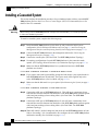
Step 3 Slide the SCE 2000 into the rack, pushing it back until the brackets (installed at the front
of the SCE 2000) meet the mounting strips or posts on both sides of the rack.
SCE 2000 4xGBE Installation and Configuration Guide
OL-7824-02
4-11
Chapter 4
Installation and Maintenance
Installing the SCE 2000 Platform
A rack with both front and back posts will have the crossrail supports installed. Slide the SCE 2000 onto
these crossrails and push it all the way back.
Figure 4-8: Sliding the SCE 2000 into the Rack
SCE 2000 4xGBE Installation and Configuration Guide
4-12
OL-7824-02
Chapter 4
Installation and Maintenance
Installing the SCE 2000 Platform
Step 4 While keeping the brackets flush against the posts or mounting strips, align the holes in
the brackets with the holes on the rack or mounting strip.
Figure 4-9: Securing the SCE 2000 to the Rack
Step 5 For each bracket, insert and tighten two appropriate screws to the rack.
Note
Since the brackets support the weight of the entire SCE 2000 chassis, be sure to use all four screws to
fasten the two rack-mount brackets to the rack posts.
Attaching a Chassis Ground Connection
Before you connect the power or turn on the power to the SCE 2000 platform, it is required that
you provide an adequate chassis Ground (protective earth) connection for the SCE 2000 chassis.
A Grounding kit is provided with each SCE 2000.
Use the Grounding kit to properly ground the SCE 2000 chassis (see SCE 2000 Component List
(on page 2-7) for details).
Warning
When installing the unit, the chassis ground connection must always be made first and disconnected
last.
SCE 2000 4xGBE Installation and Configuration Guide
OL-7824-02
4-13
Chapter 4
Installation and Maintenance
Installing the SCE 2000 Platform
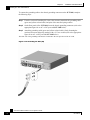
To connect the grounding cable to the chassis grounding connector on the SCE 2000, complete
the following steps:
Step 1 From the enclosed Grounding kit, remove the necessary materials: the grounding cable
(green and yellow colored cable) and pairs of hex nuts and spring washers.
Step 2 On the Rear panel of the SCE 2000, locate the chassis grounding connector (refer to the
appropriate figure for an AC- or DC-powered SCE 2000 below).
Step 3 Attach the grounding cable (green and yellow colored cable), firmly fastening the
(enclosed) hex nuts and spring washers with a #¼” hex wrench (refer to the appropriate
figure for an AC- or DC-powered SCE 2000 below).
The other side of the grounding cable must be connected to the site equivalent of the AC earth.
Figure 4-10: Grounding the Unit (AC)
SCE 2000 4xGBE Installation and Configuration Guide
4-14
OL-7824-02
Chapter 4
Installation and Maintenance
Installing the SCE 2000 Platform
Figure 4-11: Grounding the Unit (DC)
This completes the procedure for installing the SCE 2000 chassis. Proceed to the next section,
Connecting to the Power Supply, to continue the installation.
SCE 2000 4xGBE Installation and Configuration Guide
OL-7824-02
4-15
Chapter 4
Installation and Maintenance
Power Supply Overview
Power Supply Overview
The SCE 2000 is available in two power options:
•
Dual line feed AC power: SCE 2000 is shipped with two appropriate AC power supply cords.
•
Dual line feed DC power: requires appropriate cables (hex or loop connectors) (see
Connecting the DC Power Supply).
The dual power supply units supply hot-swappable, redundant power. Redundant power is useful
as a failover; if a situation occurs where one power supply is down (for instance, a power supply
fails or a new power supply needs to be installed), the SCE 2000 can continue to run properly
using the other power supply.
Each power supply has fans that cool the power supply unit. These fans also help to cool the
internal components of the SCE 2000, as they direct the air flow to the outside through vents in
the rear of the power supply unit.
The faceplates of both power supplies have a handle, an on/off switch, and one captive installation
screw. An AC-input power receptacle is available on the AC-input power supply and a DC-input
terminal block is available on the DC-input power supply.
Note that the power supply units are asymmetrical, with a screw in only one corner of the unit.
Therefore, both power supply units can be fastened only if both units are inserted in the proper
orientation. This also prevents the accidental installation of one DC unit and one AC unit. (Refer
to the following figures).
The handle of the AC unit is at the bottom of the unit.
Figure 4-12: AC Power Module
SCE 2000 4xGBE Installation and Configuration Guide
4-16
OL-7824-02
Chapter 4
Installation and Maintenance
Power Supply Overview
The handle of the DC unit is at the top of the unit.
Figure 4-13: DC Power Module
LEDs
The following LEDs are used to monitor the functioning of the power supply units:
•
•
On the power supply unit (both AC-input and DC-input):
•
IN LED (green)
•
OK LED (green)
On the Front Panel (on page 2-3):
•
Power LED: There are two Power LEDs on the front panel (Power A and Power B), one
LED corresponding to each power supply unit
On both the AC-input and DC-input power supplies, the IN LED is used to monitor the voltages
received by the platform from the power source. If the input voltages are within normal operating
ranges, the green IN LED is illuminated. If the input voltages are above or below normal ranges,
the IN LED is not illuminated.
On both the AC-input and DC-input power supplies, the OK LED is used to monitor the power
supply DC output voltages used to power the platform. The normal operating ranges for the 12
VDC output voltage is between 11.9V and 12.1V. If the output voltages are within normal
operating ranges, the green OK LED is illuminated. If the 12 VDC output voltages are above
(more than 12.1V) or below (less than 11.9V) normal ranges, the OK LED is not illuminated.
The Power A and Power B LEDs on the front panel indicate whether the corresponding power
supply unit is functioning normally.
Refer to the following tables for LED status information
Table 4-4
IN LED Status for AC-input and DC-input Power Supply Units
LED State
Power Supply Unit Condition
On (green)
The input voltage is in the required range.
Off
The input voltage is not in the required range.
SCE 2000 4xGBE Installation and Configuration Guide
OL-7824-02
4-17
Chapter 4
Installation and Maintenance
Power Supply Overview
Table 4-5
LED State
Power Supply Unit Condition
On (green)
The output voltage is in the required range (between 11.9 and 12.1 VDC).
Off
The output voltage is not within the required range. (is greater than 12.1
VDC or less than 11.9 VDC)
Table 4-6
Units
Note
OK LED Status for AC-input and DC-input Power Supply Units
Power LED (on front panel) Status for AC-input and DC-input Power Supply
LED State
Power Supply Unit Condiiton
Continuous green
Corresponding power supply unit is present and functioning normally
Red
Corresponding power supply unit present, but malfunctioning
Unlit
Corresponding power supply unit is either not present or has failed.
Simple Network Management Protocol (SNMP) monitors the activity of the power supplies. In most
cases when a power supply problem occurs, an SNMP trap is sent in SNMP and the appropriate
message is posted on the SCE 2000 CLI.
Power Supply Specifications
The following table lists the AC-input and DC-input power supply specifications for the SCE
2000 platform:
Table 4-7
SCE 2000 Power Supply Specifications
AC-input power
200W maximum
AC-input voltage rating
100 to 240 VAC
AC-input current rating
Rated for 4.5A when Vin = 100 VAC or 2A when Vin = 200 VAC
AC-input frequency rating
50 to 60 Hz
AC-input cable
18 AWG three-wire cable, with a three-lead IEC-320 receptacle on
the power supply end, and a country-dependent plug on the power
source end.
DC-input power
200W maximum
DC-input voltage rating
–48/-60 VDC nominal (–36 to–72 VDC supply tolerance)
DC-input current rating
7A at –48 VDC
DC-input cable
12 AWG or 2.5-mm copper installation wire with hex or loop
connectors
DC-input circuit breaker
One Fast 10A for each power supply unit
SCE 2000 4xGBE Installation and Configuration Guide
4-18
OL-7824-02
Chapter 4
Installation and Maintenance
Removing and Replacing a Power Supply Unit
Note
For AC-input power, we recommend powering the SCE 2000 platform from a 120 VAC, 15A receptacle
U.S. (240 VAC, 10A international) at the power source.
Removing and Replacing a Power Supply Unit
The procedures for removing and replacing the AC-input or DC-input power supply are explained
in the following sections:
ESD Warning
Warning
•
Powering Down the Power Supply Unit and Disconnecting Input Power (on page 4-19)
•
Removing the Power Supply Unit (on page 4-21)
•
Replacing the Power Supply Unit (on page 4-21)
•
Reconnecting the Power (on page 4-22)
Do not remove or install modules without using appropriate anti-static guard measures. The SCE 2000
includes an anti-static wrist strap in the accessory kit. Attach the copper tape strap to an unpainted metal
surface on the chassis. You may leave the strap connected to the chassis when your have finished.
Never install an AC power module and a DC power module in the same chassis.
Powering Down the Power Supply Unit and Disconnecting Input Power
The following sections describe how to remove power from an AC-input power supply and a DCinput power supply:
•
Powering Down an AC-Input Power Supply (on page 4-20)
•
Powering Down a DC-Input Power Supply Unit and Removing the DC-Input Leads (on page
4-20)
SCE 2000 4xGBE Installation and Configuration Guide
OL-7824-02
4-19
Chapter 4
Installation and Maintenance
Removing and Replacing a Power Supply Unit
Powering Down an AC-Input Power Supply
To power down an AC-input power supply to the SCE 2000 platform, complete the following
steps:
Warning
Make sure that the power supply unit is switched off before replacing a power supply unit (NO hotswap).
Note that one AC-input power supply can be running when the other power supply is being removed or
replaced.
Step 1 Place the on/off switch on the AC-input power supply in the OFF ({) position.
Step 2 Observe that the corresponding Power LED on the front panel turns off.
Step 3 Remove the cable from the AC-input power receptacle
This completes the procedure for powering down an AC-input power supply unit on a SCE 2000
platform. Proceed to Removing the Power Supply Unit (on page 4-21).
Powering Down a DC-Input Power Supply Unit and Removing the
DC-Input Leads
To power down a DC-input power supply to the SCE 2000 platform, complete the following
steps:
Warning
Before completing any of the following steps, and to prevent short-circuit or shock hazards, ensure that
power is removed from the DC circuit. To ensure that all power to the power supply unit is OFF, locate
the circuit breaker on the panel board that services the DC circuit, switch the circuit breaker to the OFF
position, and tape the switch handle of the circuit breaker in the OFF position.
Note that the power to the relevant power supply unit should be off, not necessarily all power to the
SCE 2000 platform. One DC-input power supply can be running when the other power supply is being
removed or replaced.
Step 1 Place the on/off switch on the DC-input power supply in the OFF ({) position.
Step 2 Make sure that that power is removed from the DC circuit by turning off the circuit
breaker or switch providing power to the DC-input power supply.
Step 3 Observe that the corresponding Power LED on the front panel turns off.
SCE 2000 4xGBE Installation and Configuration Guide
4-20
OL-7824-02
Chapter 4
Installation and Maintenance
Removing and Replacing a Power Supply Unit
Step 4 Remove the screw from one DC power line input lead receptacle and pull the lead from
the connector. Repeat this step for the remaining lead.
This completes the procedure for powering down a DC-input power supply unit on a SCE 2000
platform. Proceed to Removing the Power Supply Unit (on page 4-21).
Removing the Power Supply Unit
To remove the AC-input or DC-input power supply unit from the SCE 2000 platform, complete
the following steps:
Step 1 Using a 1/4-inch flat-blade screwdriver, loosen the captive installation screw on the
corner of the faceplate of the power supply.
Step 2 Grasp the power supply handle and pull the power supply from the router.
This completes the procedure for removing the power supply from a SCE 2000 platform.
Replacing the Power Supply Unit
Warning
Do not mix AC-input and DC-input power supply units in the same SCE 2000 platform.
To install a new power supply into a SCE 2000 platform, complete the following steps:
Step 1 Grasp the power supply unit handle with one hand and place your other hand underneath
the power supply for support.
Step 2 Fit the groove in the side of the new power supply module into the guide in the chassis.
Step 3 Gently, but firmly, slide the module into the chassis until its faceplate is flush with the
chassis rear panel.
Warning
When inserting a power supply into the SCE 2000 platform, do not use unnecessary force; slamming
the power supply into the chassis can damage the connectors on the rear of the power supply.
Step 4 Seat the power supply in the SCE 2000 platform by tightening the captive installation
screw with a 1/4-inch flat-blade screwdriver.
SCE 2000 4xGBE Installation and Configuration Guide
OL-7824-02
4-21
Chapter 4
Installation and Maintenance
Removing and Replacing a Power Supply Unit
Note
The power supply is not fully seated until you tighten the installation screw on the faceplate.
This completes the procedures for replacing a power supply in a SCE 2000 platform.
Reconnecting the Power
The following sections describe how to reconnect the AC or DC power:
•
Reconnecting AC-Input Power Supply Unit (on page 4-22)
•
Reconnecting DC-Input Power Supply Unit (on page 4-23)
Reconnecting AC-Input Power Supply Unit
The following procedures explain how to reconnect an AC-input power to the SCE 2000
platform.
If you are reconnecting DC-input power, proceed to Reconnecting DC-Input Power Supply Unit
(on page 4-23).
To reconnect the AC-input power to the SCE 2000 platform, complete the following steps:
Step 1 Plug the AC-input power cable into the AC-input power receptacle on the AC-input
power supply
Figure 4-14: Connecting the AC Power
SCE 2000 4xGBE Installation and Configuration Guide
4-22
OL-7824-02
Chapter 4
Installation and Maintenance
Removing and Replacing a Power Supply Unit
Note
For AC-input power, we recommend powering the SCE 2000 platform from a 120 VAC, 15A receptacle
U.S. (240 VAC, 10A international) at the power source.
15 A branch circuit protection is recommended.
Step 2 Plug the AC power supply cable into the AC power source.
Step 3 Turn the on/off switch to the on (⏐) position.
Step 4 Look at the IN and OK LEDs on the power supply unit and the corresponding Power
LED on the front panel. If the new AC-input power supply unit is operating properly,
these LEDs will be glowing green.
Step 5 Ensure that the power supply is properly aligned and the installation screw is tightened.
This completes the steps for reconnecting the AC-input power supply to the SCE 2000 platform.
Reconnecting DC-Input Power Supply Unit
The following procedures explain how to reconnect a DC-input power to the SCE 2000 platform.
Warning
Before completing any of the following steps, and to prevent short-circuit or shock hazards, ensure that
power is removed from the DC circuit. To ensure that all power to the power supply unit is OFF, locate
the circuit breaker on the panel board that services the DC circuit, switch the circuit breaker to the OFF
position, and tape the switch handle of the circuit breaker in the OFF position.
Note that the power to the relevant power supply unit should be off, not necessarily all power to the
SCE 2000 platform. One DC-input power supply can be running when the other power supply is being
removed or replaced.
Warning
Wiring should be done by a professional in accordance with state and local electrical codes.
To reconnect the DC-input power to the SCE 2000 platform, complete the following steps:
Step 1 Ensure that the DC power line input leads are disconnected from the power source.
Step 2 Using the number 2 Phillips screwdriver, remove the protective plate from the terminal
block.
SCE 2000 4xGBE Installation and Configuration Guide
OL-7824-02
4-23
Chapter 4
Installation and Maintenance
Removing and Replacing a Power Supply Unit
Step 3 Insert one receptacle screw into the hex or loop connector on one power line input, insert
the screw with the connector into the corresponding lead receptacle and tighten the
receptacle screw using the number 2 Phillips . Repeat for the remaining power line input
lead.
Figure 4-15: Connecting the DC Power
Note
Note
The color coding of the DC-input power supply leads depends on the color coding of the DC power
source at your site. Make certain the lead color coding you choose for the DC-input power supply
matches lead color coding used at the DC power source.
Use 12 AWG (2.5 mm) copper wire only with hex or loop connectors. Ring terminals must be UL
approved and suitable for 12 AWG wire.
Step 4 Using the number 2 Phillips screwdriver, securely fasten the protective plate to the
terminal block.
Step 5 Connect the DC power line input leads to the DC power source through a fast 4A circuit
breaker.
Step 6 Turn the on/off switch to the on (⏐) position.
Step 7 Look at the IN and OK LEDs on the power supply unit and the corresponding Power
LED on the front panel. If the new DC-input power supply unit is operating properly,
these LEDs will be glowing green.
Step 8 Ensure that the power supply is properly aligned and the installation screw is tightened.
SCE 2000 4xGBE Installation and Configuration Guide
4-24
OL-7824-02
Chapter 4
Installation and Maintenance
Fan Module Overview
This completes the steps for reconnecting the DC-input power supply to the SCE 2000 platform.
Fan Module Overview
The fan module provides cooling for the internal components. The fan drawer is a fieldreplaceable unit containing five fans, and is installed at the right rear of the SCE 2000 platform.
When a fan malfunctions, the fan module should be replaced as promptly as possible. Although it
is possible for the unit to function for some time with one non-functioning fan, this is not optimal
or recommended.
Figure 4-16: SE2000 Fan Module
When a fan failure occurs, the environment monitor will send an error message to the console. An
SNMP trap indicating that the fan is not functioning properly is also sent. Note that a fan failure is
often audible.
Removing and Replacing the Fan Module
The following sections explain how to remove and replace a fan module in a SCE 2000 platform:
•
Removing the Fan Module (on page 4-26)
•
Replacing the Fan Module (on page 4-26)
SCE 2000 4xGBE Installation and Configuration Guide
OL-7824-02
4-25
Chapter 4
Installation and Maintenance
Fan Module Overview
ESD Warning
Do not remove or install modules without using appropriate anti-static guard measures. The SCE 2000
includes an anti-static wrist strap in the accessory kit. Attach the copper tape strap to an unpainted metal
surface on the chassis. You may leave the strap connected to the chassis when your have finished.
Removing the Fan Module
Warning
When removing the fan drawer, keep hands and fingers away from the spinning fan blades. Let the fan
blades stop completely before removing the fan drawer.
To remove the fan module, complete the following steps:
Step 1 Using a 1/4-inch flat-blade screwdriver, loosen the two captive screws on the faceplate of
the fan module.
Step 2 Grasp the fan module handle and remove it from the router.
This completes the procedure for removing the fan module from a SCE 2000 platform.
Replacing the Fan Module
To install a new fan module into a SCE 2000 platform, complete the following steps:
Step 1 Grasp the fan module handle with one hand and place your other hand underneath the
fan module for support. The handle of the unit should be at the bottom.
Step 2 Fit the groove in the side of the new fan module into the guide in the chassis.
SCE 2000 4xGBE Installation and Configuration Guide
4-26
OL-7824-02
Chapter 4
Installation and Maintenance
Fan Module Overview
Step 3 Gently, but firmly, slide the module into the chassis until its faceplate is flush with the
chassis rear panel.
Figure 4-17: Inserting the Fan Module
Warning
When inserting a fan module into the SCE 2000 platform, do not use unnecessary force; slamming the
fan module into the chassis can damage the connectors on the rear of the module.
Step 4 Seat the fan module in the SCE 2000 platform by tightening the two captive installation
screws with a 1/4-inch flat-blade screwdriver.
Note
The fan module is not fully seated until you tighten the installation screws on the faceplate.
This completes the procedures for replacing a fan module in a SCE 2000 platform.
SCE 2000 4xGBE Installation and Configuration Guide
OL-7824-02
4-27
Chapter 4
Installation and Maintenance
Replacing the Battery
Replacing the Battery
The SCE 2000 has a lithium battery on its main circuit board. When the battery loses its charge,
call Cisco Technical Support to replace the battery.
Warning
Do not attempt to replace this battery yourself
Warning
There is danger of explosion if the lithium battery is incorrectly replaced. Replace only with the same
or equivalent type recommended by the manufacturer. Dispose of used batteries according to the
manufacturer’s instructions.
SCE 2000 4xGBE Installation and Configuration Guide
4-28
OL-7824-02
CHAPTER 5
Connecting the Management Interfaces and
Performing Initial System Configuration
This chapter explains how to connect the SCE 2000 platform to a local console and perform the
initial system configuration via the setup wizard that runs automatically.
Additionally, this chapter contains instructions for cabling the Fast Ethernet Management
interface.
Note
When installing a cascaded system, it is extremely important to follow the sequence of procedures
outlined in the section Installing a Cascaded System (on page 6-12).
This chapter contains the following sections:
• Connecting the Local Console
5-1
• Initial System Configuration
5-3
• Connecting the Management Interface
5-26
Connecting the Local Console
Even if you will be managing the SCE 2000 from a remote location, you must first connect the
unit to a local console and configure the initial settings for the SCE 2000 to support remote
management. When the initial connection is established, the setup utility will run automatically,
prompting you to perform the initial system configuration.
SCE 2000 4xGBE Installation and Configuration Guide
OL-7824-02
5-1
Chapter 5
Connecting the Management Interfaces and Performing Initial System Configuration
Connecting the Local Console
Setting Up the Local Console
This section provides instructions for setting up your local terminal at your workstation, to enable
you to perform the initial system configuration of the SCE 2000 system using the setup utility.
Figure 5-1: Connecting to the Local Console
Make sure that the terminal configuration is as follows:
•
9600 baud
•
8 data bits
•
No Parity
•
1 stop bits
•
No flow control
The above SCE 2000 port parameters are fixed and are not configurable.
To set up the local console, complete the following steps:
Step 1 Plug the RS-232 serial cable provided with the SCE 2000 into the CON port on the front
panel of the SCE 2000.
Make sure that you push on the RJ-45 connector (attached to the RS-232 serial cable) until you hear a
“click”, which indicates that the connector is fully inserted and secured in the receptacle. Gently pull on the
plug to confirm whether the plug is locked into the socket.
Step 2 Connect the other end of the serial cable (with an attached DB-9 connector) to the
VT100 compatible local (serial) terminal.
Step 3 Make sure the local terminal is configured as a VT-100 terminal, according to the fixed
SCE 2000 CON port parameters.
SCE 2000 4xGBE Installation and Configuration Guide
5-2
OL-7824-02
Chapter 5
Connecting the Management Interfaces and Performing Initial System Configuration
Initial System Configuration
Step 4 Press Enter several times until the Cisco logo appears on the local terminal and the setup
configuration dialog is entered.
--- System Configuration Dialog --At any point you may enter a question mark ‘?’ followed by ‘Enter’ for help.
Use ctrl-C to abort configuration dialog at any prompt.
Use ctrl-Z to jump to the end of the configuration dialog at any prompt.
Default settings are in square brackets ‘[]’.
Would you like to continue with the System Configuration Dialog? [yes/no]: y
Step 5 Type y and press Enter.
The system configuration dialog begins.
Initial System Configuration
Upon initial connection to the local terminal, as described above, the system configuration wizard
automatically runs to guide the user through the entire setup process. The wizard prompts for all
necessary parameters, displaying default values, where applicable. You may accept the default
values or define other values.
With the exception of the time settings, which take effect immediately when entered, the new
configuration is applied and saved only at the end of the dialog when approved by the user.
Therefore, if the setup dialog is aborted, no change takes place in the configuration, other than
time settings (if entered).
When the dialog is complete, you may review the new configuration before applying it. The
system displays the configuration, including parameters that were not changed. The system also
displays any errors that are detected in the configuration. When the configuration is satisfactory,
you may apply and save the new configuration.
The following table lists all the parameters included in the initial configuration. It is
recommended that you obtain values for any parameters that you will configure at this time before
beginning the setup.
Note
For further information regarding any configuration step or specific parameter, refer to the relevant
section in the Cisco Service Control Engine (SCE) Software Configuration Guide.
Table 5-1
Setup Command Parameters
Parameter
Definition
IP address
IP address of the SCE 2000.
subnet mask
Subnet mask of the SCE 2000.
default gateway
Default gateway.
hostname
Character string used to identify the SCE 2000
SCE 2000 4xGBE Installation and Configuration Guide
OL-7824-02
5-3
Chapter 5
Connecting the Management Interfaces and Performing Initial System Configuration
Initial System Configuration
admin password
Admin level password.
Character string from 4-100 characters beginning with an alpha character.
root password
Root level password.
Character string from 4-100 characters beginning with an alpha character.
password encryption
status
Enable or disable password encryption?
Time Settings
time zone name and
offset
Standard time zone abbreviation and minutes offset from UTC.
local time and date
Current local time and date. Use the format:
00:00:00 1 January 2002
SNTP Configuration
broadcast client status
Set the status of the SNTP broadcast client.
If enabled, the SCE will synchronize its local time with updates received
from SNTP broadcast servers.
unicast query interval
Interval in seconds between unicast requests for update (64 – 1024)
unicast server IP address
IP address of the SNTP unicast server.
DNS Configuration
DNS lookup status
Enable or disable IP DNS-based hostname translation.
default domain name
Default domain name to be used for completing unqualified host names
IP address
IP address of domain name server. ( maximum of 3 servers)
RDR Formatter Destination Configuration
IP address
IP address of the RDR-formatter destination
TCP port number
TCP port number of the RDR-formatter destination
Access Control Lists
Access Control List
number
How many ACLs will be necessary? What IP addresses will be
permitted/denied access for each management interface? You may want
ACLs for the following:
• Any IP access
• Telnet access
• SNMP GET access
• SNMP SET access
list entries (maximum 20
per list)
IP address, and whether permitted or denied access.
IP access ACL
ID number of the ACL controlling IP access.
telnet ACL
ID number of the ACL controlling telnet access.
SNMP Configuration
SCE 2000 4xGBE Installation and Configuration Guide
5-4
OL-7824-02
Chapter 5
Connecting the Management Interfaces and Performing Initial System Configuration
Initial System Configuration
SNMP agent status
Enable or disable SNMP management.
GET community names
Community strings to allow GET access and associated ACLs (maximum
20).
SET community names
Community strings to allow SET access and associated ACLs (maximum
20).
trap managers (maximum Trap manager IP address, community string, and SNMP version.
20)
Authentication Failure
trap status
Sets the status of the Authentication Failure traps.
enterprise traps status
Sets the status of the enterprise traps.
system administrator
Name of the system administrator.
Topology Configuration
connection mode
Is the SCE 2000 installed in bump-in-the-wire topology (inline) or out of
line using an optical splitter (receive-only)?
type of deployment
Is this a cascade topology, with two SCE 2000s connected via the cascade
ports? Or is this a single platform topology?
physically connected link In a cascade deployment this parameter sets the index for the link that this
SCE 2000 is deployed on. The options for SCE 2000 are link-0 or link-1.
(cascade topology only)
In a single-SCE 2000 Platform deployment this parameter is not relevant
since one SCE 2000 is deployed on both links. In this case the link
connected to port1-port2 is by default link-0 and the link connected to
port3-port4 is by default link-1.
priority
(cascade topology only)
on-failure behavior
(inline connection mode
only)
If this is a cascaded topology, is this SCE 2000 the primary or secondary
SCE 2000?
If this SCE 2000 is deployed inline, should the failure behavior be bypass
or cutoff of the link?
Admin status of the SCE After a reboot due to a failure, should the SCE 2000 remain in a Failure
2000 after abnormal boot status or move to operational status provided no other problem was
detected?
Following are some general instructions regarding the setup dialog:
•
All default values appear in square brackets [default].
If no value appears in the brackets [], or more than one option appears [yes/no], then this
parameter does not have a default value.
•
To accept the default value, press Enter.
•
If you need more information about any parameter, type ? and press Enter.
A help message will appear describing the expected format of the parameter and any other
requirements.
•
To jump to the end of the setup dialog at any point, accepting all remaining default values,
press ^z.
SCE 2000 4xGBE Installation and Configuration Guide
OL-7824-02
5-5
Chapter 5
Connecting the Management Interfaces and Performing Initial System Configuration
Initial System Configuration
•
In certain cases, there will be two or more logically related parameters within a menu. In these
situations, it is not permitted to jump to the end of the setup dialog until all related parameters
are configured. If you try to jump to the end of the setup dialog, the following message will
appear: “Sorry, Skipping is not allowed at this stage.”
•
Certain groups of related parameters, such as time, date, and SNTP settings, form sub-dialogs
or menus within the setup dialog. You may skip an entire menu, thereby accepting all default
values for the parameters within the menu.
Each group of related parameters is prefaced by a question, asking whether you want to enter
the menu. To skip the menu, answer no (“n”) to the question.
EXAMPLE:
Would you like to enter the SNMP configuration menu? n
•
To abort the setup dialog at any point without making any configuration changes, press ^c.
All changes already entered will be lost, with the exception of time settings.
Step 1: Configuring Initial Settings
Verify the following initial settings for the SCE 2000:
•
IP address
•
Subnet mask
•
Default gateway
All values are Internet addresses of the form ‘X.X.X.X’, where each letter corresponds to a
decimal number between 0 and 255.
To configure the initial settings, complete the following steps:
Step 1 The current IP address is displayed.
•
To accept the displayed value, press Enter.
•
To change the value, type the desired value in the format “x.x.x.x” and press Enter.
Step 2 The current subnet mask is displayed.
•
To accept the displayed value, press Enter.
•
To change the value, type the desired value in the format “x.x.x.x” and press Enter.
Step 3 The current IP address of the default gateway is displayed.
•
To accept the displayed value, press Enter.
•
To change the value, type the desired value in the format “x.x.x.x” and press Enter.
SCE 2000 4xGBE Installation and Configuration Guide
5-6
OL-7824-02
Chapter 5
Connecting the Management Interfaces and Performing Initial System Configuration
Initial System Configuration
EXAMPLE:
The following example displays a typical configuration of the IP address (10.1.5.109), subnet
mask (255.255.0.0), and default gateway (10.1.1.3).
Since the IP address and the subnet mask are related, when the IP address is changed, there is no
longer a default value of the subnet mask, and it must be entered explicitly.
Enter IP address [10.1.1.201]:10.1.5.109
Enter IP subnet mask:255.255.0.0
Enter IP address of default gateway [10.1.1.3]:
Step 2: Configuring the Hostname
The hostname is used to identify the SCE 2000. It appears as part of the CLI prompt and is also
returned as the value of the MIB-II object sysName.
The default hostname is SCE 2000.
To configure the hostname, complete the following steps:
Step 1 The current hostname is displayed.
•
To accept the displayed value, press Enter.
•
To change the value, type any desired character string and press Enter.
Enter hostname [SCE 2000]:
Step 3: Setting the Passwords
Configure the passwords as follows:
Note
•
Set the password for each authorization level (User, Admin, Root).
•
Enable/disable password encryption. When password encryption is enabled, it encrypts the
previously entered passwords.
Passwords are needed for all authorization levels in order to prevent unauthorized users from accessing
the SCE 2000. Admin level should be used by the network administrator. Root level is for use by Cisco
technician.
Passwords must meet the following criteria:
•
Minimum length: 4 characters
•
Maximum length: 100 characters
•
Begin with an alpha character
•
May contain only printable characters
SCE 2000 4xGBE Installation and Configuration Guide
OL-7824-02
5-7
Chapter 5
Connecting the Management Interfaces and Performing Initial System Configuration
Initial System Configuration
Note
Passwords are case sensitive.
Note
The default password for all levels is “cisco”.
To change the passwords, complete the following steps:
Step 1 The default User password is displayed.
•
To accept the displayed value, press Enter.
•
To change the value, type the desired string and press Enter.
Step 2 The default Admin password is displayed.
•
To accept the displayed value, press Enter.
•
To change the value, type the desired string and press Enter.
Step 3 The default Root password is displayed.
•
To accept the displayed value, press Enter.
•
To change the value, type the desired string and press Enter.
Step 4 Configure password encryption. By default, password encryption is not enabled.
•
To disable password encryption, press Enter.
•
To enable password encryption, type y and press Enter.
EXAMPLE:
Following is an example of changing all passwords. Password encryption is not enabled (default).
Enter a User password [cisco]: userin
Enter an Admin password [cisco]: mng123
Enter a Root password [cisco]: cistech
Enable passwords encryption? [no]:
Step 4: Configuring Time Settings
The time settings menu configures all time and date related parameters in the system. The time
settings menu includes the following:
•
Time zone
•
Local time
•
Date
•
SNTP menu
SCE 2000 4xGBE Installation and Configuration Guide
5-8
OL-7824-02
Chapter 5
Connecting the Management Interfaces and Performing Initial System Configuration
Initial System Configuration
You must enter the time setting menu in order to configure SNTP settings. You may choose to
skip the time settings menu if you wish to accept all default values.
Note
Unlike all other settings defined in the system configuration, setting the time is done immediately and
not at the end of the setup process.
To configure the time settings, complete the following steps:
Step 1 Enter the time settings menu.
Would you like to enter the Time settings menu? [no]: y
Type y and press Enter.
The time settings dialog begins.
Step 2 Type the time zone abbreviation and press Enter.
Enter time zone name [UTC]: CET
Step 3 Type the minutes offset from UTC and press Enter.
Enter time zone minutes offset from UTC: 60
The local time and date are displayed, and you are asked whether you want to change them.
The local time and date is 15:00:01 CET FRI 01 July 2002
Would you like to set a new time and date? [no]:
Step 4 If the time and date are correct, go to step 5.
If the time and date are not correct, answer yes to the above question, and press Enter.
Would you like to set a new time and date? [no]: y
Confirm your response and type the new time and date.
This change will take effect immediately both on the system clock and the
calendar; it will also set the time zone you entered. Are you sure?
[yes/no]: y
Enter new local time and date: 14:00:01 1 July 2002
Time zone was successfully set.
The system clock and the calendar were successfully set.
Step 5 You are asked whether you wish to enter the SNTP configuration menu.
If you do not wish to configure the SNTP, skip the rest of this section and go to Step 5: Configuring the
DNS Settings (on page 5-10).
To enter the SNTP configuration dialog, type y, and press Enter
Would you like to enter the SNTP configuration menu? [no]: y
Step 6 Configure the SNTP broadcast client. By default the SNTP broadcast client is not
enabled.
•
To disable the SNTP broadcast client, press Enter.
•
To enable the SNTP broadcast client, type y and press Enter.
Enable SNTP broadcast client? [no]:
Step 7 Define the time interval between unicast updates.
SCE 2000 4xGBE Installation and Configuration Guide
OL-7824-02
5-9
Chapter 5
Connecting the Management Interfaces and Performing Initial System Configuration
Initial System Configuration
•
To accept the displayed default value, press Enter.
•
To change the value, type the desired number of seconds (64 through 1024) and press
Enter.
Enter time interval in seconds between unicast updates [1024]:
Step 8 You may enter an IP address for the SNTP unicast server. Type in the hostname or the IP
address in the form x.x.x.x, and press Enter
Would you like to configure SNTP unicast servers? [no]: y
Enter IP address or hostname of SNTP unicast server: 10.1.1.1
EXAMPLE:
Following is a sample time setting dialog. In addition to setting the time zone, time and date are
changed, and SNTP unicast updates are configured.
Would you like to enter the Time settings menu? [no]: y
Enter time zone name [UTC]: ISR
Enter time zone minutes offset from UTC: 120
The local time and date is 15:35:23 ISR FRI July 19 2002
Would you like to set a new time and date? [no]: y
This change will take effect immediately both on the system clock and the
calendar; it will also set the time zone you entered. Are you sure?
[yes/no]: y
Enter new local time and date: 14:35:23 19 July 2002
Time zone was successfully set.
The system clock and the calendar were successfully set.
Would you like to enter the SNTP configuration menu? [no]: y
Enable SNTP broadcast client? [no]: y
Enter time interval in seconds between unicast updates [900]:
Would you like to configure SNTP unicast servers? [no]: y
Enter IP address or hostname of SNTP unicast server: 10.1.1.1
Step 5: Configuring the DNS Settings
The DNS configuration menu defines the IP address of the domain name server, which is used for
DNS lookup, as well as the default domain name, which is used to complete unqualified host
names.
You may choose to skip the DNS configuration menu if you wish to accept all default values.
To configure DNS settings, complete the following steps:
Step 1 Enter the DNS settings menu.
Would you like to enter the DNS configuration menu? [no]: y
Type y and press Enter.
The DNS settings dialog begins.
Step 2 Enable or disable DNS lookup.
•
To enable DNS lookup, press Enter.
•
To disable DNS lookup, type n and press Enter.
SCE 2000 4xGBE Installation and Configuration Guide
5-10
OL-7824-02
Chapter 5
Connecting the Management Interfaces and Performing Initial System Configuration
Initial System Configuration
Enable IP DNS-based hostname translation? [yes]:
If you choose to disable DNS lookup, skip the rest of this section and go to Step 6: Configuring the RDR
Formatter Destination (on page 5-12). The rest of the dialog is not presented, as it is irrelevant when DNS
lookup is disabled.
Step 3 Type the default domain name to be used, and press Enter.
Note that there is no default domain name.
You may accept the default domain name or enter a new one.
Enter default domain name []:
Step 4 Type the IP address of the primary domain name server and press Enter.
Enter Primary DNS IP address:
Note that there is no default for this parameter.
Step 5 You may configure up to three domain servers.
Would you like to add another Name Server? [no]:
•
To exit the DNS settings dialog, press Enter.
•
To add another domain server, type y and press Enter.
You are asked to enter the IP address of the next domain name server.
Enter Secondary DNS IP address:
Step 6 When IP addresses for all servers have been entered, exit the dialog by pressing Enter.
Would you like to add another Name Server? [no]:
EXAMPLE:
Following is a sample DNS configuration dialog. The default domain name is pcube.com, and the
IP address of the Domain Name Server is 10.1.1.230.
Would you like to enter the DNS configuration menu? [no]: y
Enable IP DNS-based hostname translation? [yes]:
Enter default domain name []: pcube.com
Enter Primary DNS IP address: 10.1.1.230
Would you like to add another Name Server? [no]:
SCE 2000 4xGBE Installation and Configuration Guide
OL-7824-02
5-11
Chapter 5
Connecting the Management Interfaces and Performing Initial System Configuration
Initial System Configuration
Step 6: Configuring the RDR Formatter Destination
The SCE 2000 passes Raw Data Records (RDRs) to an external collection system via the RDRFormatter. In order for the data to reach the correct location, the IP address of the external
collection system and its port number must be configured.
To configure the RDR-formatter destination, complete the following steps:
Step 1 Enter the RDR formatter configuration menu.
Would you like to enter the RDR-formatter configuration menu? [no]: y
Type y and press Enter.
The RDR-formatter destination dialog begins.
Step 2 Type the IP address of the RDR-formatter destination and press Enter.
Enter RDR-formatter destination’s IP address:
Note that there is no default for this parameter.
Step 3 Type the TCP port number of the RDR-formatter destination and press Enter.
Note that there is no default for this parameter.
Enter RDR-formatter destination’s TCP port number:
EXAMPLE:
Following is a sample RDR-formatter configuration dialog, assigning the IP address and TCP port
number.
Would you like to enter the RDR-formatter configuration menu? [no]: y
Enter RDR-formatter destination’s IP address: 10.1.1.230
Enter RDR-formatter destination’s TCP port number: 33000
SCE 2000 4xGBE Installation and Configuration Guide
5-12
OL-7824-02
Chapter 5
Connecting the Management Interfaces and Performing Initial System Configuration
Initial System Configuration
Step 7: Configuring Access Control Lists (ACLs)
The SCE 2000 can be configured with Access Control Lists (ACLs), which are used to permit or
deny incoming connections on any of the management interfaces.
Note
ACL #0 is a pre-defined list that permits access to all IP addresses.
Configuration of access control lists is done in two stages:
Step 1 Create the access control lists.
You may create 99 ACLs with a maximum of 20 entries per list. Each entry consists of an IP address, and
an indication of whether access is permitted or denied to this IP address.
Step 2 Assign the ACLs to the appropriate management interface. (See Step 9: Configuring the
Topology-Dependent Parameters.)
The dialog permits you to skip the creation/editing of the ACLs and go directly to assigning ACLs to the
management interfaces.
Entry Formats
Each ACL may permit/deny access to any IP address, one or more ranges of IP addresses, or one
or more individual IP address. Three entry formats are available to support these options:
•
Any IP address: Type the word “any”. Any IP address will be permitted or denied access.
•
Range of IP addresses: Type the beginning IP address in the desired range, then enter the
wildcard bits that define the range.
This wildcard functions like a reverse mask, in that all “1” bits in the wildcard indicate the
corresponding bit in the IP address should be ignored. All other bits must match the
corresponding bit in the specified IP address. Refer to the table below for examples.
Each range of IP addresses can be configured to be permitted or denied access.
•
Individual IP address: Type the desired IP address, then enter the wildcard bits 0.0.0.0.
Each individual IP address can be configured to be permitted or denied access.
Table 5-2
IP address/Wildcard bit examples
Initial IP address
Wildcard bits
Range
10.1.1.0
0.0.0.255
10.1.1.0–10.1.1.255
10.1.1.0
0.0.0.63
10.1.1.0–10.1.1.63
10.1.1.0
0.0.0.0
10.1.1.0 (individual entry)
SCE 2000 4xGBE Installation and Configuration Guide
OL-7824-02
5-13
Chapter 5
Connecting the Management Interfaces and Performing Initial System Configuration
Initial System Configuration
Order of Entries
The order of the entries in the list is important. The entries in the list are tested sequentially, and
the action is determined by the first entry that matches the connecting IP address. Therefore, when
the entry “any” appears in an Access Control List, all succeeding entries are irrelevant.
Consider two hypothetical ACLs containing the same entries in a different order.
The following list would permit access to all IP addresses, including 10.1.1.0:
permit any
deny 10.1.1.0
Note that the above list could not actually be created using the setup utility, since after the “any”
entry, no other entries could be added to the list.
The following list will deny access to IP address 10.1.1.0, but permit access to all others:
deny 10.1.1.0
permit any
If no entry in the assigned Access Control List matches the connection, or if the Access Control
List is empty, the default action is deny.
To create the access control lists, complete the following steps:
Step 1 Enter the Access Control Lists configuration menu.
Would you like to enter the Access lists configuration menu? [no]: y
Type y and press Enter.
The Access Control Lists configuration dialog begins.
Step 2 You have the option of creating or modifying Access Control Lists, or skipping this
section and proceeding directly to assign the existing ACLs to the desired management
interfaces.
Would you like create new Access lists or modify existing lists? [no]: y
If you choose not to create or edit Access Control Lists, skip to Step 9: Configuring the TopologyDependent Parameters.
Step 3 Type the number of the Access Control List to be configured (1 through 99) and press
Enter.
Note that there is no default for this parameter.
Step 4 Begin adding entries to the selected list.
Indicate whether this entry is permitted access or denied access.
•
To permit access, press Enter.
•
To deny access, type n and press Enter.
Does this entry permit access? [yes]:
Step 5 Type the IP address to be added to this list, and press Enter.
SCE 2000 4xGBE Installation and Configuration Guide
5-14
OL-7824-02
Chapter 5
Connecting the Management Interfaces and Performing Initial System Configuration
Initial System Configuration
Type “any” and press Enter to include any IP address in the ACL.
Note that there is no default for this parameter.
Enter IP address or the word ‘any’ to denote any IP address:
Step 6 If you entered a specific IP address, enter the wildcard bits to define a range of IP
addresses and press Enter. (See Entry Formats (on page 5-13).)
To define an individual IP address, type 0.0.0.0 and press Enter.
There is no default for this parameter.
Enter wildcard bits:
Step 7 The maximum number of entries in an ACL is 20.
If the “any” option was used, no other IP addresses may be added to the list.
•
To add more entries, type y and press Enter
Would you like to add another entry to this list? [no]:y
Enter up to 20 entries as described in step 5 and step 6.
•
When all entries have been added, press Enter
Would you like to add another entry to this list? [no]:
Step 8 When all entries are added to one list, you are asked whether you would like to create
another ACL. You may define up to 99 ACLs.
•
To create another ACL, type y and press Enter
Would you like to configure another list? [no]: y
Enter up to 20 IP addresses in this new ACL, as described in step 5 and step 6.
•
When all ACLs have been created, press Enter.
Would you like to configure another list? [no]:
You are now prompted to assign the desired ACLs to restrict IP and Telnet access.
Step 9 Restrict IP access to the SCE 2000 by assigning the appropriate ACL.
Type the number of the ACL to be assigned to IP access and press Enter.
To accept the default ACL, press Enter.
Enter IP access-class [0]:
Step 10 Restrict Telnet access to the SCE 2000 by assigning the appropriate ACL.
Type the number of the ACL to be assigned to the Telnet interface and press Enter.
To accept the default ACL, press Enter.
Enter Telnet access-class [0]: 2
SCE 2000 4xGBE Installation and Configuration Guide
OL-7824-02
5-15
Chapter 5
Connecting the Management Interfaces and Performing Initial System Configuration
Initial System Configuration
EXAMPLE:
This example illustrates a common access control scenario. Let us assume the following:
•
We want to permit every station to access the SCE on the management port (e.g. ping, SNMP
polling etc.).
•
We want to restrict Telnet access to only a few permitted stations.
We therefore need to create two access control lists:
•
For general IP access: permit access to all IP addresses.
•
For Telnet: permit access to the specified IP address, and deny to all others.
ACL #1 = permit any IP address. Assign to IP access.
ACL #2 = permit access to 10.1.1.0, 10.10.10.1, deny to all others. Assign to Telnet access.
Would you like to enter the Access lists configuration menu? [no]: y
Would you like create new Access lists or modify existing lists? [no]: y
Enter ACL number: 1
Does this entry permit access? [yes]:
Enter IP address or the word ‘any’ to denote any IP address: any
This entry matches every IP address, no use in adding more entries to this
list.
Would you like to configure another list? [no]: y
Enter ACL number: 2
Does this entry permit access? [yes]:
Enter IP address or the word ‘any’ to denote any IP address: 10.1.1.0
Enter wildcard bits: 0.0.0.0
Would you like to add another entry to this list? [no]:y
Does this entry permit access? [yes]:
Enter IP address or the word ‘any’ to denote any IP address: 10.10.10.1
Enter wildcard bits: 0.0.0.0
Would you like to add another entry to this list? [no]:y
Does this entry permit access? [yes]:n
Enter IP address or the word ‘any’ to denote any IP address: any
This entry matches every IP address, no use in adding more entries to this
list.
Would you like to configure another list? [no]:
Enter IP access-class [0]: 1
Enter Telnet access-class [0]: 2
EXAMPLE 2:
This example skips the first section of the dialog (creating/modifying), and proceeds directly to
assign existing ACLs.
Would
Would
Enter
Enter
you like to enter the Access lists configuration menu? [no]: y
you like create new Access lists or modify existing lists? [no]:
IP access-class [0]: 10
Telnet access-class [0]: 22
SCE 2000 4xGBE Installation and Configuration Guide
5-16
OL-7824-02
Chapter 5
Connecting the Management Interfaces and Performing Initial System Configuration
Initial System Configuration
Step 8: Configuring SNMP
Managing the SCE 2000 is possible also via a Network Management System (NMS) that supports
SNMP. By default, SNMP is disabled on the SCE 2000.
To enable SNMP management you must configure the following basic SNMP parameters:
•
SNMP traps status and managers.
•
Community strings (where an SNMP community string is a text string that acts like a
password to permit access to the SNMP agent on the SCE 2000).
To configure SNMP parameters, complete the following steps:
Step 1 Enter the SNMP configuration menu.
Would you like to enter the SNMP configuration menu? [no]: y
Type y and press Enter.
The SNMP configuration dialog begins.
Step 2 Enable SNMP management.
Type y and press Enter.
Enable SNMP management? [no]: y
If you choose to disable SNMP management, skip the rest of this section and go to Step 9: Configuring the
Topology-Dependent Parameters. The rest of the dialog is not presented, as it is irrelevant when SNMP
management is disabled.
Step 3 Type the SNMP GET community name and press Enter.
The SNMP agent that resides inside the SCE 2000 will respond only to GET requests that use this
community string.
Enter SNMP GET community name:
Note that there is no default for this parameter.
Step 4 Assign an access list to restrict the SNMP management stations that may use this GET
community.
Type a number (1 through 99) or type “0” to permit access to all IP addresses, and press Enter.
Enter Access list number allowing access with this community string, use ‘0’
to allow all:
Step 5 The maximum number of GET communities is 20.
•
To add more entries, type y and press Enter
•
Would you like to add another SNMP GET community? [no]:y
Enter up to 20 SNMP GET communities as described in step 3 and step 4.
•
When all entries have been added, press Enter
Would you like to add another SNMP GET community? [no]:
Step 6 Type the SNMP SET community name and press Enter.
SCE 2000 4xGBE Installation and Configuration Guide
OL-7824-02
5-17
Chapter 5
Connecting the Management Interfaces and Performing Initial System Configuration
Initial System Configuration
The SNMP agent that resides inside the SCE 2000 will respond only to SET requests that use this
community string.
Enter SNMP SET community name:
Note that there is no default for this parameter.
Step 7 Assign an access list to restrict the SNMP management stations that may use this SET
community.
Type a number (1 through 99) or type “0” to permit access to all IP addresses, and press Enter.
Enter Access list number allowing access with this community string, use ‘0’
to allow all:
Step 8 The maximum number of SET communities is 20.
•
To add more entries, type y and press Enter
Would you like to add another SNMP SET community? [no]:y
Enter up to 20 SNMP SET communities as described in step 6 and step 7.
•
When all entries have been added, press Enter
Would you like to add another SNMP SET community? [no]:
Step 9 Enter the SNMP trap managers menu.
Would you like to configure SNMP trap managers? [no]: y
Type y and press Enter.
The SNMP trap managers dialog begins.
If you choose not to configure SNMP trap managers, the dialog skips to the authentication failure trap
status. (See step 14.)
Step 10 Type the trap manager IP address and press Enter.
Enter SNMP trap manager IP address:
Note that there is no default for this parameter.
Step 11 Type the trap manager community string and press Enter.
Note that there is no default for this parameter.
Enter SNMP trap manager community string:
Step 12 Type the number of the trap manager SNMP version (1 or 2c) and press Enter
Note that there is no default for this parameter.
Enter trap manager SNMP version:
Step 13 The maximum number of trap managers is 20.
•
To add more entries, type y and press Enter
Would you like to add another SNMP trap manager? [no]:y
Enter up to 20 trap managers as described in step 10 through step 12.
•
When all entries have been added, press Enter
Would you like to add another SNMP trap manager? [no]:
Step 14 Configure the Authentication Failure trap status.
SCE 2000 4xGBE Installation and Configuration Guide
5-18
OL-7824-02
Chapter 5
Connecting the Management Interfaces and Performing Initial System Configuration
Initial System Configuration
•
To disable the Authentication Failure trap, press Enter.
•
To enable the Authentication Failure trap, type y and press Enter.
Enable the ‘Authentication Failure’ trap [no]:
Step 15 Configure the SCE enterprise trap status.
•
To disable the SCE enterprise traps, type n press Enter.
•
To enable the SCE enterprise traps, type y and press Enter.
Enable the SCE enterprise traps []:
Step 16 Type the name of the system administrator and press Enter.
Note that there is no default for this parameter.
Enter system administrator contact name []:
EXAMPLE:
Following is a sample SNMP configuration, configuring one trap manager, one GET community,
and one SET community, and enabling the authentication failure trap, as well as all enterprise
traps.
Would you like to enter the SNMP configuration menu? [no]: y
Enable SNMP management? [no]: y
Enter SNMP GET community name[]: public
Enter Access list number allowing access with this community string, use ‘0’
to allow all: 0
Would you like to add another SNMP GET community? [no]:
Enter SNMP SET community name[]: private
Enter Access list number allowing access with this community string, use ‘0’
to allow all: 2
Would you like to add another SNMP SET community? [no]:
Would you like to configure SNMP trap managers? [no]: y
Enter SNMP trap manager IP address: 10.1.1.253
Enter SNMP trap manager community string: public
Enter trap manager SNMP version: 2c
Would you like to add another SNMP trap manager? [no]:
Enable the ‘Authentication Failure’ trap [no]: y
Enable SCE enterprise traps []: y
Enter system administrator contact name []: John Smith
SCE 2000 4xGBE Installation and Configuration Guide
OL-7824-02
5-19
Chapter 5
Connecting the Management Interfaces and Performing Initial System Configuration
Initial System Configuration
Step 9: Configuring the Topology-Dependent Parameters
The topology configuration menu is a series of guided questions relating to the deployment of the
SCE 2000 in the network and its mode of operation. Values for the parameters are configured
based on the user answers.
The correct value for each parameter must be ascertained before configuring the system to make
sure that the system will function in the desired manner. (See Topology (on page 3-1) for a
comprehensive discussion of topology and the related parameters.)
Note
Values may not be requested for all topology-dependent parameters, as certain parameters do not apply
to all topologies.
There are six topology-related parameters:
•
•
•
Connection mode: Can be either of the following, depending on the physical installation of
the SCE 2000.
•
Inline
•
Receive-only
Type of deployment: Can be one of the following, depending on the actual deployment:
•
Single-SCE Platform: a single SCE 2000 is deployed on one or two SCAS BB Console
links
•
Cascade: two cascaded SCE 2000s are deployed on two SCAS BB Console links, working
as a fully redundant solution.
Physically connected link (cascade topology only): In a cascade topology, the user must
assign an index to each of the links. This index is used to identify the services per link.
In a single-SCE Platform deployment, the indices of the links cannot be changed by the user
and are:
•
link-0: the link connected to ports 1 and 2
•
link-1: the link connected to ports 3 and 4
In a cascade deployment, the user must define which link is connected to which SCE 2000.
The index must be different for each SCE 2000. In this case the user can choose one of the
following:
•
•
Link-0: the link connected to this SCE 2000 is identified as 0.
•
Link-1: the link connected to this SCE 2000 is identified as 1.
Priority (cascade topology only): In a cascade topology, this parameter determines which
SCE 2000 is chosen as the active SCE 2000 in the “active election” procedure. This decision
is taken only when both SCE 2000s are starting up together. If there is one working SCE 2000
and the other is just starting up, then the working one will automatically be chosen as active
and the other one as standby. This parameter can be set to one of the following:
•
Primary
SCE 2000 4xGBE Installation and Configuration Guide
5-20
OL-7824-02
Chapter 5
Connecting the Management Interfaces and Performing Initial System Configuration
Initial System Configuration
•
•
•
Secondary
On-Failure behavior: Determines the behavior of the SCE 2000 upon failure, or reboot. One
of the following link modes may be chosen for the SCE 2000 in the cases of failure or reboot:
•
Bypass: traffic is bypassed using the internal bypass card.
•
Cutoff: the link is forced down.
Admin status after abnormal reboot: This parameter determines whether the SCE 2000
returns to full operational mode after abnormal (not user-requested) boot, or stays in nonoperational mode, in which the SCE 2000 behaves as in failure mode. This parameter can be
set to one of the following:
•
Operational
•
Non-operational
The procedure described below is a presentation of all the questions in the topology configuration.
In actual practice, all questions may not be presented for a particular configuration, depending on
the topology deployed.
Study the examples that follow to understand the procedure for various topologies.
To configure topology dependent parameters, complete the following steps:
Step 1 Enter the topology configuration menu.
Would you like to enter the Topology configuration menu? [no]: y
Type y and press Enter.
The topology configuration dialog begins.
Step 2 Specify the connection mode.
•
To define inline connection mode, press Enter.
•
To define receive-only connection mode, type 2 and press Enter.
Enter Connection mode:
1- inline
2- receive-only
Enter your choice [1]:
Step 3 Specify the deployment type.
•
To specify a Single-SCE Platform deployment, press Enter.
•
To specify a Cascade deployment, type y and press Enter.
Is this a cascade deployment? [no]:
Step 4 Specify the physically-connected-link index.
•
To specify link-0, press Enter.
•
To specify link-1, type 1 and press Enter.
Enter Physically connected link:
0- link-0
1- link-1
Enter your choice [0]:
Step 5 Specify the SCE 2000 priority.
SCE 2000 4xGBE Installation and Configuration Guide
OL-7824-02
5-21
Chapter 5
Connecting the Management Interfaces and Performing Initial System Configuration
Initial System Configuration
•
To specify Primary, press Enter.
•
To specify Secondary, type 2 and press Enter.
Enter SCE 2000 priority:
1- primary
2- secondary
Enter your choice [1]:
Step 6 Specify the On-failure link behavior.
•
To specify Bypass, press Enter.
•
To specify Cutoff, type 2 and press Enter.
Enter On-failure behavior:
1- bypass
2- cutoff
Enter your choice [1]:
Step 7 Specify the status of the SCE 2000 after abnormal boot.
•
To specify Operational status after abnormal boot, press Enter.
•
To specify Not-Operational status after abnormal boot, type 2 and press Enter.
Enter admin status of the SCE after abnormal boot:
1- Operational
2- Not-Operational
Enter your choice [1]:
The following examples present the procedure for configuring the topology-related parameters for
various topologies.
EXAMPLE #1:
Following is a sample topology configuration for a non-redundant topology using an optical
splitter, that is, a single SCE 2000 connected in receive-only connection mode, to one or two GBE
links
Would you like to enter the Topology configuration menu? [no]: y
Would you like to enter the Topology configuration menu? [no]: y
Enter Connection mode:
1- inline
2- receive-only
Enter your choice [1]: 2
Is this a cascade deployment? [no]: no
Enter admin status of the SCE after abnormal boot:
1- Operational
2- Not-Operational
Enter your choice [1]: 1
Data collection for the system configuration is completed.
All other parameter values are automatically assigned by the system.
SCE 2000 4xGBE Installation and Configuration Guide
5-22
OL-7824-02
Chapter 5
Connecting the Management Interfaces and Performing Initial System Configuration
Initial System Configuration
EXAMPLE #2:
Following is a sample topology configuration for a non-redundant bump-in-the-wire (inline)
topology. In this topology, a single SCE 2000 is connected to one or two GBE links.
When the inline connection mode is specified, the user must specify the on-failure link behavior.
Would you like to enter the Topology configuration menu? [no]: y
Enter Connection mode:
1- inline
2- receive-only
Enter your choice [1]: 1
Is this a cascade deployment? [no]: no
Enter On-failure behavior:
1- bypass
2- cutoff
Enter your choice [1]: 1
Enter admin status of the SCE after abnormal boot:
1- Operational
2- Not-Operational
Enter your choice [1]: 1
Data collection for the system configuration is completed.
EXAMPLE #3:
Following is a sample topology configuration for a secondary SCE 2000 in a redundant inline
topology. In this topology there are two SCE 2000s that are cascaded via the cascade GBE ports
(ports 3 and 4). Each SCE 2000 is connected inline to both sides (subscribers/network) of one
GBE link.
In this case, the user must specify the physically-connected-link index (link-0 in our example), the
priority of the SCE 2000, and the on-failure link behavior.
Would you like to enter the Topology configuration menu? [no]: y
Enter Connection mode:
1- inline
2- receive-only
Enter your choice [1]: 1
Is this a cascade deployment? [no]: yes
Enter Physically connected link:
0- link-0
1- link-1
Enter your choice [0]: 0
Enter SCE 2000 priority:
1- primary
2- secondary
Enter your choice [1]: 2
Enter On-failure behavior:
1- bypass
2- cutoff
Enter your choice [1]: 1
Enter admin status of the SCE after abnormal boot:
1- Operational
2- Not-Operational
Enter your choice [1]: 1
Data collection for the system configuration is completed.
SCE 2000 4xGBE Installation and Configuration Guide
OL-7824-02
5-23
Chapter 5
Connecting the Management Interfaces and Performing Initial System Configuration
Initial System Configuration
Step 10: Completing and Saving the Configuration
When you have completed the entire configuration, the system checks for errors. If errors are
found, a warning message appears. When the configuration is error-free, you may apply and save
it.
To complete and save the configuration, complete the following steps:
Step 1 The system informs you that data collection is complete.
It is recommended that you view the entire new configuration before it is applied.
Type y and press Enter.
Note that there is no default.
If there are no errors, go to step 3.
Data collection for the system configuration is completed.
Would you like to view the new configuration before it is applied? [yes/no]:
y
Step 2 If any errors are detected, you may choose to view them.
Press Enter.
Found errors in the new configuration, would you like to view them? [yes]:
The following errors were found:
Warning - RDR formatter destination 10.1.1.1 is not allowed in the IP
access-class.
Step 3 You are asked whether to apply and save the configuration.
Apply and Save this configuration? [yes/no]:
•
To apply and save the configuration, type y and press Enter.
•
To abort the setup procedure without applying or saving the configuration (recommended
if there are errors), type n and press Enter.
Setup procedure aborted, no configuration changes made.
If the setup is aborted, the dialog is ended.
Step 4 If there are no errors, the system requests confirmation of either a yes or no answer, in
order to prevent mistakes.
Type the appropriate answer (y or n) and press Enter.
The running configuration would be overwritten by the changes you have just
entered, are you sure? [yes/no]:
The selected action is carried out by the system.
•
If the apply and save action is not confirmed (no), the setup is aborted.
Setup procedure aborted, no configuration changes made.
•
If the apply and save action is confirmed (yes), the configuration is applied and saved.
The new running configuration will be saved to the startup configuration.
Step 5 If the configuration was applied and saved, you may also save it to a file at a remote
station.
SCE 2000 4xGBE Installation and Configuration Guide
5-24
OL-7824-02
Chapter 5
Connecting the Management Interfaces and Performing Initial System Configuration
Initial System Configuration
Do you want to save a copy of the startup configuration file in a remote
station? [no]:
To save the configuration to a remote station, type y and press Enter.
The system will ask for FTP path:
Enter a full FTP path of the remote destination:
Step 6 The system informs you that the configuration is complete.
Committing configuration...
Configuration completed successfully.
Saving configuration...
Writing general configuration file to temporary location...
Backing-up general configuration file...
Copy temporary file to final location...
Done!
This completes the procedures for initial configuration of the SCE 2000 platform.
EXAMPLE #1:
Following is an example of a configuration that the user aborted due to errors detected in the
configuration.
Note that no confirmation is requested for the decision to abort the setup. Had there been no
errors, confirmation would have been requested before aborting.
Data collection for the system configuration is completed.
Would you like to view the new configuration before it is applied? [yes/no]:
n
Found errors in the new configuration, would you like to view them? [yes]: y
The following errors were found:
Warning - RDR formatter destination 10.1.1.1 is not allowed in the IP
access-class.
Warning - default Gateway 10.1.1.1 is not allowed in the IP access-class.
Warning - IP Access list (1) conflicts with Telnet Access list (2) as
follows:
Access list 2 permits all addresses while Access list 1 denies it.
Apply and Save this configuration? [yes/no]: n
Setup procedure aborted, no configuration changes made.
SCE 2000 4xGBE Installation and Configuration Guide
OL-7824-02
5-25
Chapter 5
Connecting the Management Interfaces and Performing Initial System Configuration
Connecting the Management Interface
EXAMPLE #2:
Following is an example of a configuration that was applied and saved to the startup configuration
as well as to an FTP site.
Although not demonstrated in this example, it is recommended that you always view the
configuration before applying it.
Data collection for the system configuration is completed.
Would you like to view the new configuration before it is applied? [yes/no]:
Apply and Save this configuration? [yes/no]: y
(New configuration would be displayed here)
The running configuration would be overwritten by the changes you have just
entered, are you sure? [yes/no]:y
The new running configuration will be saved to the startup configuration.
Do you want to save a copy of the startup configuration file in a remote
station? [no]:y
Enter a full FTP path of the remote destination:
ftp://vk:[email protected]/h:/copyofstartup.txt
Committing configuration...
Configuration completed successfully.
Saving configuration...
Writing general configuration file to temporary location...
Backing-up general configuration file...
Copy temporary file to final location...
Done!
EXAMPLE #3:
Following is an example of a configuration that was aborted, although no errors were detected.
Data collection for the system configuration is completed.
Would you like to view the new configuration before it is applied? [yes/no]:
Apply and Save this configuration? [yes/no]: n
The changes you have just entered would be discarded, are you sure?
[yes/no]:y
Setup procedure aborted, no configuration changes made.
Connecting the Management Interface
The procedures for cabling the management port and testing connectivity between the SCE 2000
and the remote management host are explained in the following sections:
Note
•
Cabling the Management Port (on page 5-27)
•
Verifying Management Interface Connectivity (on page 5-28)
By default, the management port is configured to auto-negotiation enabled. To change this default
setting, refer to Configuring the Management Interface Speed and Duplex Parameters.
SCE 2000 4xGBE Installation and Configuration Guide
5-26
OL-7824-02
Chapter 5
Connecting the Management Interfaces and Performing Initial System Configuration
Connecting the Management Interface
Cabling the Management Port
The SCE 2000 has two management ports, labeled Mng1 and Mng 2. Use the Mng 1 port. The
Mng 2 port is currently not operational.
To cable the management port, complete the following steps:
Step 1 Take the Ethernet cable provided (with attached RJ-45 connector) and plug it into the
Mng 1 port on the front panel of the SCE 2000, as shown in the following figure.
Figure 5-2: Cabling the Management Port
Step 2 Connect the other end of the Ethernet cable into your management network.
Make sure that you push on the RJ-45 connector attached to the cable until you hear a click, which indicates
that the connector is fully inserted and secured in the receptacle. Gently pull on the plug to confirm whether
the plug is locked into the socket.
If the Link LED on the SCE 2000 management port does not light, try removing the cable and reinserting it
firmly into the module socket. To disconnect the plug from the socket, press down on the raised portion on
top of the plug, releasing the latch. You should hear an audible click indicating the latch has released.
Carefully pull the plug out of the socket.
If the management port Link LED on the SCE 2000 still does not light, verify that the cable is connected
correctly to the appropriate network element on its second end.
T
SCE 2000 4xGBE Installation and Configuration Guide
OL-7824-02
5-27
Chapter 5
Connecting the Management Interfaces and Performing Initial System Configuration
Connecting the Management Interface
Verifying Management Interface Connectivity
If the SCE 2000 platform has been powered up, test now to verify that connectivity has been
established between the SCE 2000 and the remote management host. If the SCE 2000 platform is
not powered up, perform this step after starting the SCE 2000 platform.
To verify that connectivity has been established between the SCE 2000 and the remote
management host, complete the following steps:
Step 1 After you connect the cable to the appropriate Mng port and to your network, check the
Mng 1 port LEDS.
There are two Mng LEDs: Link/Active, and 10/100/1000 (refer to Front Panel).
At this point, check that the Link/Active LED is green.
The state of the 10/100/1000 LED will depend on the Ethernet network settings.
Green indicates 100 Mbps and ‘Off’ indicates 10 Mbps.
Step 2 Test connectivity. From the host that you intend to use for remote management, ping to
the SCE 2000 by typing ping and the SCE 2000 IP address, and pressing Enter (see the
example, below).
Note
Please note that only step 2 above, is performed from the remote management host (Mng port
connection).
This verifies that an active connection exists between the specified station and the management port.
The ping program sends an echo request packet to an IP address and then awaits a reply. Ping output can
help you evaluate path-to-host reliability, delays over the path, and whether the host can be reached or is
functioning.
SCE 2000 4xGBE Installation and Configuration Guide
5-28
OL-7824-02
Chapter 5
Connecting the Management Interfaces and Performing Initial System Configuration
Connecting the Management Interface
This completes the procedures for connecting the management interfaces and for initial
configuration of the SCE 2000 platform. Proceed to the next chapter for a description of the
procedures for cabling the Gigabit Ethernet ports and for configuring Gigabit Ethernet (GBE)
interface parameters.
EXAMPLE:
The following example displays a typical ping response where the target IP address is 10.1.1.201.
C:\>ping 10.1.1.201
pinging 10.1.1.201 ...
PING 10.1.1.201: 56 data bytes
64 bytes from host (10.1.1.201): icmp_seq=0. time=0.
64 bytes from host (10.1.1.201): icmp_seq=1. time=0.
64 bytes from host (10.1.1.201): icmp_seq=2. time=0.
64 bytes from host (10.1.1.201): icmp_seq=3. time=0.
----10.1.1.201 PING Statistics---4 packets transmitted, 4 packets received, 0% packet
round-trip (ms) min/avg/max = 0/0/0
ms
ms
ms
ms
loss
SCE 2000 4xGBE Installation and Configuration Guide
OL-7824-02
5-29
CHAPTER 6
Cabling the Line Ports and Completing the
Installation
This chapter provides instructions for cabling the Gigabit Ethernet ports for both one and two
SCE 2000 topologies, and for configuring Gigabit Ethernet (GBE) interface parameters. In a
topology utilizing two SCE 2000s (cascade), this includes the cascade ports as well as the line
ports.
Note
When installing a cascaded system, it is extremely important to follow the sequence of procedures
outlined in the section Installing a Cascaded System (on page 6-12).
Note
When installing an External Optical Bypass module, the SCE 2000 line ports are connected to the
module. See Cabling the External Optical Bypass Module (on page A-6) for complete instructions.
This chapter contains the following sections:
• Connecting the line ports to the network 6-1
• Installing a Cascaded System
6-12
• Loading and Activating a Service Control Application
6-16
Connecting the line ports to the network
The procedures for cabling the line ports, configuring the interface parameters, and testing
connectivity of the links are explained in the following sections:
•
Cabling Diagrams (on page 6-2)
•
Configuring the GBE Interface Parameters (on page 6-7)
•
Connecting the GBE Line Interface Ports (on page 6-8)
•
Testing Connectivity: Examining Link LEDs, GBE Counters ("Testing Connectivity:
Examining Link LEDs and Counters" on page 6-10)
SCE 2000 4xGBE Installation and Configuration Guide
OL-7824-02
6-1
Chapter 6
Cabling the Line Ports and Completing the Installation
Connecting the line ports to the network
Cabling Diagrams
Before beginning, find the appropriate cabling diagram for the topology in your installation:
•
•
Single SCE 2000 topologies
•
Single Link: Inline Topology (on page 6-2)
•
Single Link: Receive-only Topology (on page 6-3)
•
Dual Link: Single SCE 2000 Topologies (on page 6-3)
Dual SCE 2000 topologies (cascaded)
•
Note
Dual Link: Two SCE 2000s Topology (on page 6-5)
When installing a cascaded system, it is extremely important to follow the sequence of procedures
outlined in the section Installing a Cascaded System.
Single Link: Inline Topology
In the inline, or bump-in-the-wire topology, the SCE 2000 resides physically on the GBE (Gigabit
Ethernet) link between the subscribers, which are usually connected through either a BRAS (in
DSL access), a PDSN (in wireless access), a CMTS (in the Cable access), or a switch or router
aggregator (in other topologies), and the network, where the SCE 2000 usually connects to a
router or layer 3 switch network element.
Figure 6-1: Cabling Diagram for Single Link Inline Topology
In the single link inline topology, either the first GBE link (first two ports) of the SCE 2000 or the
second GBE link (third and fourth ports) can be used, as illustrated in the diagram above. The
remaining pair of ports is unused.
Either port 1 or port 3 is used for connecting to the network element that is deployed on the
subscriber side of the SCE 2000 while port 2 or port 4 is used for connecting to the network
element that is deployed on the network side of the SCE 2000.
Inline topology requires both Receive and Transmit fibers
SCE 2000 4xGBE Installation and Configuration Guide
6-2
OL-7824-02
Chapter 6
Cabling the Line Ports and Completing the Installation
Connecting the line ports to the network
Single Link: Receive-only Topology
In this topology, an optical splitter resides physically on the GBE link that the SCE 2000 should
monitor. The optical splitter is connected to the SCE 2000 via Rx links only.
In this topology, the traffic passes through the optical splitter, which splits traffic to the SCE 2000.
Note
Receive-only topologies can also be implemented using a switch. Such a switch must support SPAN
functionality that includes separation between ingress and egress traffic and multiple SPAN-ports
destinations.
Figure 6-2: Cabling Diagram for Single SCE 2000 Single Link Receive-only Topology
The single link receive-only topology cabling is similar to that for single link inline, in that either
the first GBE link (first two ports) or the second GBE link (third and fourth ports) can be used, as
illustrated in the diagram above. The remaining pair of ports is unused.
Either port 1 or port 3 is used for connecting to the network element that is deployed on the
subscriber side of the SCE 2000 while port 2 or port 4 is used for connecting to the network
element that is deployed on the network side of the SCE 2000.
Dual Link: Single SCE 2000 Topologies
In this topology, one SCE 2000 is connected to two full duplex, GBE links. The SCE 2000 may
be either inline, to support both monitoring and traffic control functionality, or receive-only for
traffic monitoring functionality only.
When one SCE 2000 supports two links, the first two ports are connected to one link, while ports
3 and 4 are connected to the second link as follows;
•
Port 1: Link 1, Subscriber side
•
Port 2: Link 1, Network side
•
Port 3: Link 2, Subscriber side
•
Port 4: Link 2, Network side
SCE 2000 4xGBE Installation and Configuration Guide
OL-7824-02
6-3
Chapter 6
Cabling the Line Ports and Completing the Installation
Connecting the line ports to the network
As with the single link cabling, inline topologies require both Receive and Transmit fibers, while
Receive-only systems use only Receive fibers.
Note
Receive-only topologies can be implemented using either an optical splitter or a switch. If a switch is
used, it must support SPAN functionality that includes separation between ingress and egress traffic and
multiple SPAN-ports destinations.
The following two diagrams illustrate the connections for dual links, with a single SCE 2000
deployed for both inline and receive-only topologies.
Figure 6-3: Cabling Diagram: Dual Link One SCE 2000 Inline
Figure 6-4: Cabling Diagram: Dual Link One SCE 2000 Receive-only
SCE 2000 4xGBE Installation and Configuration Guide
6-4
OL-7824-02
Chapter 6
Cabling the Line Ports and Completing the Installation
Connecting the line ports to the network
Dual Link: Two SCE 2000s Topology
In this topology, two SCE 2000s are connected to two full duplex, GBE links, providing full
redundancy through cascading the two SCE 2000s. The SCE 2000s may be either inline, to
support both monitoring and traffic control functionality, or receive-only for traffic monitoring
functionality only.
Note
When installing a cascaded system, it is extremely important to follow the sequence of procedures
outlined in the section Installing a Cascaded System (on page 6-12).
Note
Receive-only topologies can be implemented using either an optical splitter or a switch. If a switch is
used, it must support SPAN functionality that includes separation between ingress and egress traffic and
multiple SPAN-ports destinations.
When two SCE 2000s are used, the first two ports in each SCE 2000 are connected to the links,
while ports 3 and 4 are the cascade ports that are used for communicating between the two SCE
2000s as follows:
SCE 2000 #1
•
Port 1: Link 1, Subscribers side
•
Port 2: Link 1, Network side
•
Port 3: Cascade, connect to Port 4 in SCE 2000 #2
•
Port 4: Cascade, connect to Port 3 in SCE 2000 #2
SCE 2000 #2
•
Port 1: Link 2, Subscribers side
•
Port 2: Link 2, Network side
•
Port 3: Cascade, connect to Port 4 in SCE 2000 #1
•
Port 4: Cascade, connect to Port 3 in SCE 2000 #1
SCE 2000 4xGBE Installation and Configuration Guide
OL-7824-02
6-5
Chapter 6
Cabling the Line Ports and Completing the Installation
Connecting the line ports to the network
Inline topologies require connecting both Receive and Transmit fibers to the SCE 2000. Cascade
ports always require both Receive and Transmit fibers to be connected.
The following diagram illustrates the connections for a dual link, two SCE 2000-platform inline
topology.
Figure 6-5: Cabling Diagram: Dual Link Inline Topology Two Cascaded SCE 2000s
SCE 2000 4xGBE Installation and Configuration Guide
6-6
OL-7824-02
Chapter 6
Cabling the Line Ports and Completing the Installation
Connecting the line ports to the network
Configuring the GBE Interface Parameters
By default, the SCE 2000 GBE line interface ports are configured with auto-negotiation disabled.
The procedure for enabling auto-negotiation for the GBE line interface ports is explained in the
following section.
Note
Auto-negotiation must be disabled when the SCE 2000 is deployed via an external optical splitter
(receive-only topology)
.
Note
If you change any parameters, you must save the new configuration settings.
Type copy running-config startup-config, and press Enter
Configuring GigabitEthernet Auto-Negotiation
To configure GBE auto-negotiation for a specified GBE port interface, complete the following
steps:
Step 1 To enter the Global Configuration Mode, at the SCE 2000# prompt, type configure, and
press Enter.
The SCE 2000(config)# prompt appears.
Step 2 To enter the desired GBE port interface, type interface GigabitEthernet
0/portnumber, and press Enter, where portnumber is the number of the selected
port (1-4).
The SCE 2000(config if)# prompt appears.
Step 3 Type auto-negotiate and press Enter.
The SCE 2000(config if)# prompt appears.
Step 4 To return to Global Configuration Mode, type exit and press Enter.
The SCE 2000(config)# prompt appears.
Repeat this procedure to configure auto-negotiation for the other GBE port interfaces as needed.
SCE 2000 4xGBE Installation and Configuration Guide
OL-7824-02
6-7
Chapter 6
Cabling the Line Ports and Completing the Installation
Connecting the line ports to the network
Connecting the GBE Line Interface Ports
The following sections present the general procedure for cabling the GBE interface ports. Refer to
Cabling Diagrams (on page 6-2) to find the appropriate cabling diagram for the topology of your
system for the specific connections required.
Note
When installing an External Optical Bypass module, the SCE 2000 line ports are connected to the
module. See Cabling the External Optical Bypass Module (on page A-6) for complete instructions.
Fiber Specifications
The following table presents the fiber specifications. The SCE 2000 may be ordered with either
Multimode or Single Mode transceivers The transceiver type is indicated on the front panel under
the ports. Note that both transceivers on any individual SCE 2000 are the same, either 850nm
Multimode OR 1310nm Single Mode.
Table 6-1
Fiber Specifications
SCE Model
Transceiver
Transmit Power
Receive Power Typical (Max.) Distance
SCE 2000 4xGBE
MM
850nm Multimode
–9.5 to –4 dBm
–17 to 0 dBm
• 750m for 50µm Core
Diameter MMF
• 400m for 62.5µm Core
Diameter MMF
SCE 2000 4xGBE
SM
1310nm FRP laser
Single Mode
–9.5 to –3 dBm
–20 to 3 dBm
10 km for 9.0µm Core
Diameter SMF
Cabling the GBE Port
Warning
Class 1 laser. Avoid exposure to radiation and do not stare into open aperture.
To cable the SCE 2000 GBE line port, complete the following steps:
Step 1 Take the appropriate fiber optic cable (see Fiber Specifications (on page 6-8)) and plug it
into the appropriate GBE port on the front panel of the SCE 2000.
SCE 2000 4xGBE Installation and Configuration Guide
6-8
OL-7824-02
Chapter 6
Cabling the Line Ports and Completing the Installation
Connecting the line ports to the network
Make sure to push on the connector until you hear a click, which indicates that the connector is fully
inserted and secured in the receptacle. Always make sure that you insert the connector completely into the
socket.
Figure 6-6: Cabling the GBE Interface
Step 2 Verify that the link LED is green.
If the link LED does not light, try removing the network cable plug and reinserting it firmly into the module
socket.
SCE 2000 4xGBE Installation and Configuration Guide
OL-7824-02
6-9
Chapter 6
Cabling the Line Ports and Completing the Installation
Connecting the line ports to the network
Testing Connectivity: Examining Link LEDs and Counters
If the SCE 2000 platform has been powered up, test now to verify that connectivity has been
established on all links. If the SCE 2000 platform is not powered up, perform this step after
starting the SCE 2000 platform.
Examining the LEDs
The GBE Link LED must be green in order to verify that an active connection exists.
The GBE Rx and Tx LEDs (if flashing green) indicate that traffic is being received or transmitted
by the SCE 2000 platform, respectively.
Note that in an inline topology, the Rx and Tx LEDs indicate that packets are being
received/transmitted by the SCE 2000 platform.
In optical splitter topologies, the Rx LEDs are the sole indicators. The Tx LEDs do not “blink”,
since the Tx is not connected to the port in this topology.
Viewing the Counters to Verify that the Network Traffic is
Reaching the Device
In an inline topology, you can monitor traffic via the platform counters for both the Rx and Tx
connections. The counters increase, together with the increased number of packets that flow
through the SCE 2000 for both Rx and Tx.
However, in external switch topologies, the counters for the Tx do not increment, that is, Tx does
not have a function in monitoring traffic, as it is disconnected.
To view the Gigabit Ethernet port status, complete the following steps:
Step 1 At the SCE 2000# prompt, type show interface GigabitEthernet 0/interface-
number.
This displays the port link and auto-negotiation status.
SCE 2000 4xGBE Installation and Configuration Guide
6-10
OL-7824-02
Chapter 6
Cabling the Line Ports and Completing the Installation
Connecting the line ports to the network
EXAMPLE:
The following example displays a system response.
SCE 2000#show interface GigabitEthernet 0/1
Auto negotiation configured: Enabled
Actual Status:
Link is on
Auto negotiation: Enabled
Bandwidth: 100000Kbps
Burst-size: 50000bytes
Auto-negotiation for bump-in-the-wire topology may be enabled or disabled. For receive-only
topologies, using an external splitter, auto-negotiation must be disabled.
To view the Gigabit Ethernet counters, complete the following steps:
Step 1 At the SCE 2000# prompt, type show interface GigabitEthernet 0/interface-
number counters.
This displays the GigabitEthernet counters. This command enables you to verify that traffic is taking place.
You can see that the counters increase, together with the increased number of packets that flow through the
SCE 2000.
Again, in bump-in-the-wire topology, both the Rx and Tx counters apply as traffic monitors. For receiveonly topologies, using an external splitter, only the Rx counters apply.
EXAMPLE:
The following example shows the counters of the first Gigabit Ethernet interface.
SCE 2000#show interface GigabitEthernet 0/1 counters
In total octets: 100
In good unicast packets: 90
In good multicast packets: 0
In good broadcast packets: 10
In packets discarded: 0
In packets with CRC/Alignment error: 0
In undersized packets: 0
In oversized packets: 0
Out total octets: 93*2^32+1022342538
Out unicast packets: 858086051
Out non unicast packets: 0
Out packets discarded: 0
You are now ready to continue to the next stage, loading and activating an SCE application.
SCE 2000 4xGBE Installation and Configuration Guide
OL-7824-02
6-11
Chapter 6
Cabling the Line Ports and Completing the Installation
Installing a Cascaded System
Installing a Cascaded System
This section outlines the installation procedures for a redundant solution with two cascaded SCE
2000 platforms. Refer to the Cisco Service Control Engine (SCE) CLI Command Reference for
details of the CLI commands.
Warning
When working with two SCE 2000 platforms with split-flow and redundancy, it is extremely important
to follow this installation procedure.
To install a cascaded system, complete the following steps:
Step 1 Install both SCE 2000 platforms, power them up, and perform the initial system
configuration. (See Installation and Maintenance (on page 4-1) and Connecting the
Management Interfaces and Performing Initial System Configuration (on page 5-1).)
Step 2 Connect both SCE 2000 platforms to the management station.(See Connecting the
Management Interface (on page 5-26))
Step 3 Connect the cascade ports. (See Dual Link: Two SCE 2000 platforms Topology.)
Step 4 Set topology configurations for each SCE 2000 platform via the connection-mode
options. (See Topology-Related Parameters for Redundant Topologies (on page 6-13).)
Step 5 Make sure that the SCE 2000 platforms have synchronized and active SCE 2000
platform was selected.
Use the show interface linecard 0 connection-mode command.
Step 6 If you want to start with bypass/sniffing, change the link mode to your required mode in
both SCE 2000 platforms on both links. The bypass mode will be applied only to the
active SCE 2000 platform. (See Link Mode (on page 6-14).)
Step 7 Make sure that the link mode is as you required. (See Monitoring the System (on page 6-
15).)
Use the show interface linecard 0 link mode command.
Step 8 Connect the traffic port of SCE 2000 platform #1. This will cause a momentary down
time until the network elements from both sides of the SCE 2000 platform auto-negotiate
with it and start working (when working inline). (See Dual Link: Two SCE 2000
platforms Topology.)
Step 9 Connect the traffic port of SCE 2000 platform #2, this will cause a momentary down
time until the network elements from both sides of the SCE 2000 platform auto-negotiate
with it and start working (when working inline). (See Dual Link: Two SCE 2000
platforms Topology.)
Step 10 When full control is needed, change the link mode on both SCE 2000 platforms on both
links to ‘forwarding’. It is recommended to first configure the active SCE 2000 platform
and then the standby. (See Link Mode (on page 6-14).)
SCE 2000 4xGBE Installation and Configuration Guide
6-12
OL-7824-02
Chapter 6
Cabling the Line Ports and Completing the Installation
Installing a Cascaded System
Step 11 You can now start working with the Subscriber Manager.
CLI Commands
This section presents CLI commands relevant to the configuration and monitoring of a redundant
system.
Use the following commands to configure and monitor a redundant system:
•
connection-mode
•
[no] force failure-condition
•
Show interface linecard ‘number’ connection-mode
•
Show interface linecard ‘number’ physically-connected-links
Topology-Related Parameters for Redundant Topologies
All four of the topology-related parameters are required when configuring a redundant topology.
•
Connection mode: Redundancy is achieved by cascading two SCE 2000 platforms. Therefore
the connection mode for both SCE 2000 platforms may be either:
•
Inline-cascade
•
Receive-only-cascade
•
Physically-connected-links: For each of the cascaded SCE 2000 platforms, this parameter
defines the number of the link (Link 0 or Link 1) connected to this SCE 2000 platform.
•
Priority: For each of the cascaded SCE 2000 platforms, this parameter defines whether it is
the primary or secondary device.
•
On-failure: For each of the cascaded SCE 2000 platforms, this parameter determines whether
the system cuts the traffic or bypasses it when the SCE 2000 platform either has failed or is
booting.
Configuring the Connection Mode
Use the following command to configure the connection mode, including the following
parameters:
•
inline/receive only
•
physically connected links
•
behavior upon failure of the SCE 2000 platform
•
primary/secondary
SCE 2000 4xGBE Installation and Configuration Guide
OL-7824-02
6-13
Chapter 6
Cabling the Line Ports and Completing the Installation
Installing a Cascaded System
To configure the connection mode:
Step 1 From the SCE 2000(config if)# prompt, type connection-mode inline-
cascade/receive-only-cascade [physically-connected-links
{link-0/link-1}] [priority {primary/secondary}] [on-failure
{bypass/cutoff}] and press Enter.
EXAMPLE 1
Use the following command to configure the primary SCE 2000 platform in a two-SCE 2000
platform inline topology. Link 1 is connected to this SCE 2000 platform and the behavior of the
SCE 2000 platform if a failure occurs is bypass.
SCE 2000(config if)# connection-mode inline-cascade physically-connected-links
link-1 priority primary on-failure bypass
EXAMPLE 2
Use the following command to configure the SCE 2000 platform that might be cascaded with the
SCE 2000 platform in Example 1. This SCE 2000 platform would have to be the secondary SCE
2000 platform, and Link 0 would be connected to this SCE 2000 platform, since Link 1 was
connected to the primary. The connection mode would be the same as the first, and the behavior
of the SCE 2000 platform if a failure occurs is also bypass.
SCE 2000(config if)# connection-mode inline-cascade physically-connected-links
link-0 priority secondary on-failure bypass
Link Mode
The SCE 2000 platform has an internal hardware card used to maintain the links even when the
SCE 2000 platform fails. This hardware card has four possible modes of operation:
•
bypass
•
forwarding
•
cutoff
•
sniffing
Normally, the link mode is selected by the SCE 2000 platform software according to the
configured connection-mode. However, the link-mode command can be used to enforce a
specific desired mode. This may be useful when debugging the network, or in cases where we
would like the SCE 2000 platform just to forward the traffic. (Note that this is only relevant to
inline topologies even though the configuration is available also when in receive-only mode.)
The following link mode options are available:
•
Forwarding: forwards traffic on the specified link to the SCE 2000 platform for processing.
•
Bypass: stops all forwarding of traffic on the specified link to the SCE 2000 platform. Traffic
still flows on the link, but is not processed in any way by the SCE 2000 platform.
This does not affect the redundancy states.
SCE 2000 4xGBE Installation and Configuration Guide
6-14
OL-7824-02
Chapter 6
Cabling the Line Ports and Completing the Installation
Installing a Cascaded System
•
Sniffing: allows the SCE 2000 platform to forward traffic on the specified link through the
bypass mechanism while still analyzing the traffic passively.
Sniffing is permitted to be configured for for all links, only (use the all-links option).
•
Cutoff: completely cuts off flow of traffic through the specified link.
Note the following recommendations and restrictions:
•
Since the SCE 1000 platform has only one link, the link is not specified.
•
Since the SCE 2000 platforms have more than one link, it is required to specify the link. The
link designations are different for the GBE and FE platforms, as follows:
•
SCE 2000 4xGBE: GBE1-GBE2/GBE3-GBE4
•
SCE 2000 4/8xFE: LINK1/LINK2
•
Use the 'all-links' option to configure the link mode for all links (SCE 2000 platforms
only).
•
It is recommended that both links be configured together. Use the all-links option.
•
Link mode is relevant only to inline topologies.
•
It is recommended that in cascaded topologies, both SCE 2000 platforms be configured for
the same link mode, otherwise the service will be unpredictable.
•
Sniffing can only be configured for all links, therefore, to configure sniffing, the all-links
option is required, not just recommended.
•
The default link mode is forwarding. When other link modes are selected, active service
control is not available and any service control configuration will not be applicable.
To set the link mode:
Step 1 From the SCE 2000 (config if)# prompt, type link-mode [<link>|all-
links] [forwarding|bypass|sniffing|cutoff] and press Enter.
Monitoring the System
Use the following commands to view the current connection mode and link mode parameters.
To view the current connection mode:
Step 1 From the SCE 2000# prompt, type show interface linecard 0
connection-mode and press Enter.
SCE 2000 4xGBE Installation and Configuration Guide
OL-7824-02
6-15
Chapter 6
Cabling the Line Ports and Completing the Installation
Loading and Activating a Service Control Application
To view the current link mode:
Step 1 From the SCE 2000# prompt, type show interface linecard 0 link mode
and press Enter.
To view the current link mappings:
Step 1 From the SCE 2000# prompt, type show interface linecard 0
physically-connected-links and press Enter.
Loading and Activating a Service Control Application
The SCE 2000 platform provides the basic functionalities of Service Control analysis and
enforcement. A Service Control solution requires that a Service Control application be loaded into
the platform, to take advantage of the unique SCE platform capabilities.
Loading and activating an application includes the following stages:
•
Downloading the application provided as an SLI file to the SCE 2000 disk.
•
Activating the application.
•
Configuring the application.
The detailed procedure of how to perform these operations is not specified and described in this
manual. For further details, refer to the following documentation:
•
Service Control Application Suite for Broadband User Guide
•
Service Control Application Suite for Broadband Reference Guide
SCE 2000 4xGBE Installation and Configuration Guide
6-16
OL-7824-02
CHAPTER 7
Basic SCE 2000 Platform Operations
This chapter describes how to start up the SCE 2000 platform, reboot, and shutdown. It also
describes how to manage configurations.
This chapter contains the following sections:
• Starting the SCE 2000 Platform
7-1
• Managing SCE 2000 Configurations
7-4
• Performing Complex Configurations
7-10
• Rebooting and Shutting Down the SCE Platform 7-11
Starting the SCE 2000 Platform
The procedures for starting the SCE 2000 platform are explained in the following sections:
•
Checking Conditions Prior to System Startup (on page 7-1)
•
Starting the System and Observing Initial Conditions (on page 7-2)
Checking Conditions Prior to System Startup
Check the following conditions before you start your SCE 2000 platform:
•
Both power supply units are installed and connected
•
First-time startup at installation:
•
•
SCE 2000 platform connected to local console (CON port)
•
The console terminal is turned on and properly configured
Subsequent startups
•
Line and Cascade interfaces are properly cabled (optional)
•
SCE 2000 platform is connected to at least one of the following types of management
stations:
•
Direct connection to local console (CON port)
•
Remote management station via the LAN (Mng port)
SCE 2000 4xGBE Installation and Configuration Guide
OL-7824-02
7-1
Chapter 7
Basic SCE 2000 Platform Operations
Starting the SCE 2000 Platform
You are now ready to start your SCE 2000 platform. Proceed to the section Starting the System
and Observing Initial Conditions (on page 7-2).
Starting the System and Observing Initial Conditions
After installing your SCE 2000 platform and connecting cables, , complete the following steps to
start the SCE 2000 platform:
Step 1 Make sure the power cables are connected to the SCE 2000 platform.
Step 2 Plug the AC power supply cables into the AC power source, or make sure the circuit
breakers at the DC panels are turned to the on position. Turn both power switches on (⏐).
Step 3 Listen for the fans; you should immediately hear them operating.
Step 4 During the boot process, observe the following LEDs:
Note
•
Both Power LEDs should be green.
•
Bypass LED should be green while the SCE 2000 is on bypass and unlit when the bypass
is turned off.
•
The Status LED should be a constant orange while booting. After a successful boot, the
Status LED is flashing green.
It takes a several minutes for the SCE 2000 to boot and for the status LED to change from orange to
flashing orange or flashing green.
Step 5 Observe the initialization process. When the system boot is complete, the console screen
displays a script and system banner similar to the following:
Cisco Internetwork Operating System Software
IOS (tm) 7300 Software (C7300-JS-M), Version 12.1(9), CISCO RELEASED VERSION
Copyright (c) 1986-2001 by Cisco Systems, Inc.
Compiled Tue 17-Jul-01 01:51 by biff
Image text-base:0x40008970, data-base:0x40BF8000
Step 6 When you start up the SCE 2000 platform for the first time, the system automatically
enters the setup wizard, which prompts you for configuration information for initial
system configuration. On the console terminal, after the system displays the system
banner and hardware configuration, you will see the System Configuration Dialog
prompt. (Refer to Initial System Configuration (on page 5-3) for a complete description
of the setup wizard.)
You have the option of proceeding with the setup wizard to configure the system, or exiting from setup and
using configuration commands to configure global (system-wide) and interface-specific parameters. You do
not have to configure the interfaces immediately.
If the system does not complete each of the steps in the startup procedure, proceed to Chapter 7,
Troubleshooting (on page 8-1) for troubleshooting recommendations and procedures.
SCE 2000 4xGBE Installation and Configuration Guide
7-2
OL-7824-02
Chapter 7
Basic SCE 2000 Platform Operations
Starting the SCE 2000 Platform
Final Tests
The procedures for performing the final tests to verify that the SCE 2000 is functioning properly
are explained in the following sections:
•
Verifying Operational Status (on page 7-3)
•
Viewing the User Log ("Viewing the User Log Counters" on page 7-3)
Verifying Operational Status
After all the ports are connected, verify that the SCE 2000 is not in a Warning state.
To verify that the SCE 2000 is not in a warning state, complete the following steps:
Step 1 On the SCE 2000 Front panel, examine that the Status LED is flashing green.
Step 2 To display the operation status of the system, at the SCE 2000# prompt, type show
system operation-status and press Enter.
A message displaying the operation status of the system appears. If the system is operating in order, the
following message appears:
System Operation status is Operational.
EXAMPLE:
The following example displays a sample output where the LEDs appear red/orange:
SCE 2000#show system operation-status
System Operation status is Operational
Viewing the User Log Counters
View the user log for errors that occurred during the installation process.
To display the user log device counters, complete the following steps:
Step 1 At the SCE 2000# prompt, type show logger device User-File-Log
counters and press Enter.
SCE 2000 4xGBE Installation and Configuration Guide
OL-7824-02
7-3
Chapter 7
Basic SCE 2000 Platform Operations
Managing SCE 2000 Configurations
EXAMPLE:
The following example shows the current User-File-Log device counters.
SCE 2000#show logger device user-file-log counters
Logger device User-File-Log counters:
Total info messages: 1
Total warning messages: 0
Total error messages: 0
Total fatal messages: 0
If there are “Total error messages” or “Total fatal messages”, use the show logger device
User-File-Log command to display details about the errors.
Managing SCE 2000 Configurations
The procedures for managing SCE 2000 configurations are explained in the following sections:
•
Viewing Configuration (on page 7-4)
•
Saving the Configuration Settings (on page 7-7)
•
Recovering a Previous Configuration (on page 7-9)
Viewing Configuration
When you enter configuration commands, it immediately effects the SCE 2000 platform operation
and configuration. This configuration, referred to as the running-config, is saved in the SCE
2000 platform volatile memory and is effective while the SCE 2000 platform is up. After reboot,
the SCE 2000 platform loads the startup-config, which includes the non-default
configuration as saved by the user, into the running-config.
The SCE 2000 platform provides commands for:
•
Viewing the running configuration
•
Viewing the startup configuration
After configuring the SCE 2000 platform, you may query for the running configuration using the
command show running-config. This command displays the non-default running
configuration. To view the complete SCE 2000 platform running configuration, including both
default and user-configured configuration, you may use the option all-data in the show
running-config command.
SCE 2000 4xGBE Installation and Configuration Guide
7-4
OL-7824-02
Chapter 7
Basic SCE 2000 Platform Operations
Managing SCE 2000 Configurations
To view the running configuration, complete the following steps:
Step 1 At the SCE 2000# prompt, type show running-config.
The system shows the running configuration.
SCE 2000#show running-config
#This is a general configuration file (running-config).
#Created on 15:50:56 CET MON February 11 2002
#cli-type 1
#version 1
clock timezone CET 1
snmp-server community “public” ro
snmp-server host 10.1.1.253 traps version 1 “public”
interface LineCard 0
connection-mode active
no silent
no shutdown
flow-aging default-timeout UDP 60
interface FastEthernet 0/0
ip address 10.1.5.109 255.255.0.0
interface FastEthernet 0/1
interface FastEthernet 0/2
exit
line vty 0 4
no timeout
exit
SCE 2000#
One of the useful show commands is the show version command. This command displays
global static information on the SCE 2000 platform as software and hardware version, image
build time, system uptime, last open packages names and information on the SLI application
assigned.
SCE 2000 4xGBE Installation and Configuration Guide
OL-7824-02
7-5
Chapter 7
Basic SCE 2000 Platform Operations
Managing SCE 2000 Configurations
To show the version information for the SCE 2000 platform software and hardware, complete the
following steps:
Step 1 At the SCE 2000# prompt, type show version.
The system shows the version information.
SCE 2000#show version
System version: Version 2.5.2 Build 240
Build time: Jan 11 2005, 07:34:47
Software version is: Version 2.5.2 Build 240
Hardware information is:
rx
: 0x0075
dp
: 0x1808
tx
: 0x1708
ff
: 0x0077
cls
: 0x1721
cpld
: 0x0025
Lic
: 0x0176
rev
: G001
Bootrom
: 2.1.0
L2 cache
: Samsung 0.5
lic type
: MFE
optic mode
:
Part number: 53AA-BXC1-AAAA
Revision: A02A
Software revision: G001
Serial number: 043P6982
Power Supply type: AC
SML Application information is:
Application file: /tffs0/temp.sli
Application name:
Application help:
Original source file:
H:\work\Emb\jrt\V2.5\sml\actions\drop\drop_basic_anyflow.san
Compilation date: Wed, September 22, 2004 at 21:25:21
Compiler version: SANc v2.50 Build 32 gcc_codelets=true built on: Tue
September 22 2004 09:51:57 AM.;SME plugin v1.1
Default capacity option used.
Logger status: Enabled
Platform: SCE 2000 - 4xFE
Management agent interface version: SCE Agent 2.5.1 Build 18
Software package file:
ftp://vk:[email protected]/P:/EMB/LatestVersion/2.5.2/se1000.pkg
SCE 2000 uptime is 21 minutes, 37 seconds
SCE 2000#
Another useful show commands is the show system-uptime command. This command
displays information similar to the last line above, which indicates how long the system has been
running since the last reboot.
SCE 2000 4xGBE Installation and Configuration Guide
7-6
OL-7824-02
Chapter 7
Basic SCE 2000 Platform Operations
Managing SCE 2000 Configurations
To show the system uptime for the SCE 2000 platform software and hardware, complete the
following steps:
Step 1 At the SCE 2000# prompt, type show system-uptime.
The system shows how long the system has been running since the last reboot.
SCE 2000#show system-uptime
SCE 2000 uptime is 21 minutes, 37 seconds
SCE 2000#
Saving the Configuration Settings
When you make changes to the current running configuration and you want those changes to
continue to be valid when the system restarts, you must save the changes before leaving the
management session, that is, you must save the running configuration to the startup configuration
file.
As mentioned before, SCE 2000 platform provides multiple interfaces for the purpose of
configuration and management. All interfaces supply an API to the same database of the SCE
2000 platform and any configuration made through one interface is reflected through all
interfaces. Furthermore, when saving the running configuration to the startup configuration from
any management interface, all configuration settings are saved regardless of the management
interface used to set the configuration.
To save configuration changes, complete the following steps:
Step 1 At the SCE 2000# prompt, type show running-config to view the running
configuration.
The running configuration is displayed.
Step 2 Check the displayed configuration to make sure that it is set the way you want. If not,
make the changes you want before saving.
Step 3 Type copy running-config startup-config.
The system saves all running configuration information to the configuration file, which is used when the
system reboots.
The configuration file holds all information that is different from the system default in a file called
config.txt located in the directory: tffs0:system.
SCE 2000 4xGBE Installation and Configuration Guide
OL-7824-02
7-7
Chapter 7
Basic SCE 2000 Platform Operations
Managing SCE 2000 Configurations
EXAMPLE:
The following example shows the running configuration file.
SCE 2000#show running-config
#This is a general configuration file (running-config).
#Created on 15:50:56 CET MON February 11 2002
#cli-type 1
#version 1
clock timezone CET 1
snmp-server community “public” ro
snmp-server host 10.1.1.253 traps version 1 “public”
interface LineCard 0
connection-mode active
no silent
no shutdown
flow-aging default-timeout UDP 60
interface FastEthernet 0/0
ip address 10.1.5.109 255.255.0.0
interface FastEthernet 0/1
interface FastEthernet 0/2
exit
line vty 0 4
no timeout
exit
SCE 2000#
SCE 2000#copy running-config startup-config
Writing general configuration file to temporary location...
Backing-up general configuration file...
Copy temporary file to final location...
SCE 2000#
For backup purposes, the old startup-config file is saved under the directory:
tffs0:system/prevconf. Refer to Recovering a Previous Configuration (on page 7-9) for
an explanation on how to recover previous configuration.
To remove a configuration command from the running-config, use the no form of the command.
EXAMPLE:
The following example illustrates how to remove all DNS settings from the running
configuration.
SCE 2000(config)#no ip name-server
SCE 2000(config)#
SCE 2000 4xGBE Installation and Configuration Guide
7-8
OL-7824-02
Chapter 7
Basic SCE 2000 Platform Operations
Managing SCE 2000 Configurations
Recovering a Previous Configuration
When you save a new configuration, the system automatically backs up the old configuration in
the directory tffs0:system/prevconf/. Up to nine versions of the startup configuration
file are saved, namely config.tx1-config.tx9, where config.tx1 is the most recently
saved file.
You can view the old startup configuration files using the CLI command more.
Restoring a previous startup configuration means renaming the file so it overwrites the startup
configuration (config.txt) file.
To restore a previous startup configuration, complete the following steps:
Step 1 At the SCE 2000# prompt, type more tffs0:system/prevconf/config.txt
to view the configuration file.
The system displays the configuration information stored in the file.
Step 2 Read the configuration information to make sure it is the configuration you want to
restore.
Note that you cannot undo the configuration restore command.
Step 3 Type
copy tffs0:system/prevconf/config.tx1
tffs0:system/config.txt.
The system sets the startup configuration to the configuration from config.tx1.
SCE 2000 4xGBE Installation and Configuration Guide
OL-7824-02
7-9
Chapter 7
Basic SCE 2000 Platform Operations
Performing Complex Configurations
EXAMPLE:
The following example displays a saved configuration file and then restores the file to overwrite
the current configuration.
SCE 2000#more tffs0:system/prevconf/config.tx1
#This is a general configuration file (running-config).
#Created on 19:36:07 UTC THU February 14 2002
#cli-type 1
#version 1
interface LineCard 0
no silent
no shutdown
interface FastEthernet 0/0
ip address 10.1.5.109 255.255.0.0
interface FastEthernet 0/1
interface FastEthernet 0/2
exit
line vty 0 4
exit
SCE 2000#copy tffs0:system/prevconf/config.tx1 tffs0:system/config.txt
SCE 2000#
Performing Complex Configurations
After you have installed your SCE 2000 platform hardware, checked all external connections,
turned on the system power, allowed the system to boot up, and performed the initial system
configuration, you might need to perform more complex configurations, which are beyond the
scope of this publication.
For further information on system and interface configuration, refer to the following documents:
•
Cisco Service Control Engine (SCE) Software Configuration Guide
•
Cisco Service Control Engine (SCE) CLI Command Reference
SCE 2000 4xGBE Installation and Configuration Guide
7-10
OL-7824-02
Chapter 7
Basic SCE 2000 Platform Operations
Rebooting and Shutting Down the SCE Platform
Rebooting and Shutting Down the SCE Platform
Rebooting the SCE Platform
Rebooting the SCE 2000 platform is required after installing a new firmware, in order for that
firmware to take effect. There might be other occasions where rebooting the SCE 2000 platform
is necessary.
Note
When the SCE restarts, it loads the startup configuration, so all changes made in the running
configuration will be lost. You are advised to save the running configuration before performing reload,
as described in Saving the Configuration Settings (on page 7-7).
To reboot your SCE 2000 platform, complete the following steps:
Step 1 At the SCE 2000# prompt, type reload and press Enter.
A confirmation message appears.
Step 2 Type Y to confirm the reboot request and press Enter.
EXAMPLE:
The following example shows the commands for system reboot.
SCE 2000# reload
Are you sure? y
the system is about to reboot, this will end your CLI session
SCE 2000 4xGBE Installation and Configuration Guide
OL-7824-02
7-11
Chapter 7
Basic SCE 2000 Platform Operations
Rebooting and Shutting Down the SCE Platform
Shutting Down the SCE Platform
Shutting down the SCE 2000 platform is required before turning the power off. This helps to
ensure that non-volatile memory devices in the SCE 2000 platform are properly flushed in an
orderly manner.
Note
When the SCE restarts, it loads the startup configuration, so all changes made in the running
configuration will be lost. You are advised to save the running configuration before performing reload,
as described in Saving the Configuration Settings (on page 7-7).
To shut down your SCE 2000 platform, complete the following steps:
Step 1 Connect to the serial console port (The CON connector on the SCE 2000 platform front
panel, 9600 baud).
The SCE 2000# prompt appears.
Step 2 Type reload shutdown.
A confirmation message appears.
Step 3 Type Y to confirm the shutdown request and press Enter.
EXAMPLE:
The following example shows the commands for system shutdown.
SCE 2000#reload shutdown
You are about to shut down the system.
The only way to resume system operation after this
is to cycle the power off, and then back on.
Continue?
y
IT IS NOW SAFE TO TURN THE POWER OFF.
Note
Since the SCE 2000 platform can recover from the power-down state only by being physically turned
off (or cycling the power), this command can only be executed from the serial CLI console. This
limitation helps prevent situations in which a user issues this command from a Telnet session, and then
realizes he/she has no physical access to the SCE 2000 platform.
SCE 2000 4xGBE Installation and Configuration Guide
7-12
OL-7824-02
CHAPTER 8
Troubleshooting
Your SCE 2000 platform went through extensive testing before leaving the factory. However, if
you encounter problems starting it, use the information in this chapter to help isolate the cause of
the problems. The procedures in this chapter assume that you are troubleshooting the initial
system startup, and that your SCE 2000 platform is in the original factory configuration. If you
have removed or replaced components or changed any default settings, the recommendations in
this chapter might not apply. Make sure to review the safety warnings listed in the Regulatory
Compliance and Safety Information for the Cisco Service Control Engine document that
accompanied your SCE 2000 platform before using the troubleshooting procedures in this
chapter.
This chapter contains the following sections:
• Troubleshooting Overview 8-1
• Problem Solving Using a Subsystems Approach 8-9
Troubleshooting Overview
This section describes the troubleshooting methods used in this chapter and describes how the
SCE 2000 platform is divided into subsystems for more efficient problem solving. If you are
unable to easily solve the problem, contact a customer service representative for assistance and
further instructions. Provide the representative with the following information:
•
Date you received the router
•
Chassis serial number
•
Type of software and release number
•
Brief description of the problem you are having
•
Brief explanation of the steps you have taken to isolate and resolve the problem
•
Maintenance agreement or warranty information
SCE 2000 4xGBE Installation and Configuration Guide
OL-7824-02
8-1
Chapter 8
Troubleshooting
Troubleshooting Overview
The following table shows the general troubleshooting strategy described in this chapter. Refer to
this table, as necessary, to follow the steps to isolate problems to a specific subsystem and resolve
the problem if possible.
Table 8-1
Troubleshooting Strategy for Startup Problems
Action
Yes
No
Step 2 Power A/Power B LEDs on?
Go to Step 3
Troubleshoot power system
and go to Step 3.
Step 3 Status LED red (failure)
Troubleshoot
software
installation and go
to Step 4.
Go to Step 4
Step 4 Management interface
operational?
Go to Step 5
Troubleshoot management
system and go to Step 4.
Step 5 Link interfaces operational?
Go to Step 6
Troubleshoot link interface
system and go to Step 5.
Step 1 Turn power on. Go to Step 2
Step 6 System startup successful (all ⎯
interfaces operating normally).
⎯
Troubleshooting Tools
There are three tools that will help you to successfully troubleshoot your SCE 2000 installation:
•
CLI Commands for Troubleshooting (on page 8-2)
•
The User Log (on page 8-4)
•
Check the LEDs (on page 8-7)
CLI Commands for Troubleshooting
Use the following commands to provide information to help you troubleshoot installation of your
SCE 2000 platform. Refer to Cisco Service Control Engine (SCE) Software Configuration Guide
or the Cisco Service Control Engine (SCE) CLI Command Reference for more information.
Note
Remember that if the management interface is not operational, you should connect the SCE 2000
platform to a local console so that you can enter CLI commands for troubleshooting.
•
Troubleshooting firmware package installation:
•
Boot system <filename>: Specifies and verifies the package file to be installed.
Error messages or other output identify problems with the package file.
Following is a sample output from the Boot system command.
SCE 2000 4xGBE Installation and Configuration Guide
8-2
OL-7824-02
Chapter 8
Troubleshooting
Troubleshooting Overview
SCE 2000(config)#boot system ftp://vk:[email protected]/downloads/SENum.pkg.pkg
Verifying package file SENum.pkg.pkg…
Package file verified OK.
•
Troubleshooting the management subsystem:
•
show interface FastEthernet 0/0: Displays IP address and auto-negotiation
information for the management interface.
Following is a sample output from the show interface FastEthernet command.
ip address: 10.1.6.145
subnet mask: 255.255.0.0
Configured speed: auto, configured duplex: auto
AutoNegotiation is On, link is Up, actual speed: 100, actual duplex: half
•
show ip default-gateway: Displays the IP address of the configured default gateway.
Following is a sample output from the show ip default-gateway command.
Default gateway: 10.1.1.1
•
show ip route: Displays the entire routing table and the destination of last resort (defaultgateway).
Following is a sample output from the show ip route command.
gateway of last resort is
•
10.1.1.1
show access-lists: Shows all access-lists or a specific access list.
Following is a sample output from the show access-lists command.
Standard IP access list 1
Permit 10.1.1.0, wildcard bits 0.0.0.255
deny
any
•
show telnet: Displays the status of the telnet server daemon (status) or any active
Telnet sessions (sessions).
Following is a sample output from the show telnet command.
show telnet sessions
There is 1 active telnet session:
Index | Source
================
0
| 10.1.1.201
show telnet status
Telnet deamon is enabled.
•
show line vty timeout: Shows the timeout configured for Telnet sessions.
Following is a sample output from the show line vty timeout command.
Timeout is 30 minutes
•
Troubleshooting the link interface subsystem:
•
show interface GigabitEthernet 0/#: Displays information for a specific GBE
Interface.
Following is a sample output from the show interface command.
SCE 2000 4xGBE Installation and Configuration Guide
OL-7824-02
8-3
Chapter 8
Troubleshooting
Troubleshooting Overview
ip address: 10.1.6.145
subnet mask: 255.255.0.0
Configured duplex: auto
AutoNegotiation is On, link is Up, actual duplex: half
•
show interface GigabitEthernet 0/# counters: Displays the values of counters of a
GBE interface.
Following is a sample output from the show interface counters command.
In total octets: 191520
In good unicast packets: 560
In good multicast packets: 0
In good broadcast packets: 0
In packets discarded: 0
In packets with CRC/Alignment error: 0
In undersized packets: 0
In oversized packets: 0
Out total octets: 0
Out unicast packets: 0
Out non unicast packets: 0
Out packets discarded: 0
Refer to The User Log (on page 8-4) for an explanation of commands related to the user log.
The User Log
The user log is an ASCII file that can be viewed in any editor. It contains a record of system
events, including startup, shutdown and errors. You can use the Logger to view the user log to
determine whether or not the system is functioning properly, as well as for technical support
purposes.
The Logging System
Events are logged to one of two log files. After a file reaches maximum capacity, the events
logged in that file are then temporarily archived. New events are then automatically logged to the
alternate log file. When the second log file reaches maximum capacity, the system then reverts to
logging events to the first log file, thus overwriting the temporarily archived information stored in
that file.
Basic operations include:
•
Copying the User Log to an external source
•
Viewing the User Log
•
Clearing the User Log
•
Viewing/clearing the User Log counters
SCE 2000 4xGBE Installation and Configuration Guide
8-4
OL-7824-02
Chapter 8
Troubleshooting
Troubleshooting Overview
Copying the User Log
You can view the log file by copying it to an external source or to disk. This command copies
both log files to the local SCE 2000 platform disk or any external host running a FTP server.
To copy the user log to an external source, complete the following steps:
Step 1 From the SCE 2000# prompt, type logger get user-log file-name
ftp://username:password@ipaddress/path and press Enter.
The SCE 2000# prompt appears.
To copy the user log to an internal location, complete the following steps:
Step 1 From the SCE 2000# prompt, type logger get user-log file-name
target-filename
and press Enter.
The SCE 2000# prompt appears.
Viewing the User Log
Note
This command is not recommended when the user log is large. Copy a large log to a file to view it (see
Copying the User Log (on page 8-5))
To view the user log, complete the following steps:
Step 1 From the SCE 2000# prompt, type more user log and press Enter.
The user log appears, followed by the SCE 2000# prompt.
SCE 2000 4xGBE Installation and Configuration Guide
OL-7824-02
8-5
Chapter 8
Troubleshooting
Troubleshooting Overview
Clearing the User Log
You can clear the contents of the user log at any time. It is recommended that a copy be made
before the log is cleared.
To clear the user log, complete the following steps:
Step 1 From the SCE 2000# prompt, type clear logger device user-file-log and press Enter.
Step 2 The system asks Are you sure?
Step 3 Type Y and press Enter.
The SCE 2000# prompt appears.
Viewing the User Log Counters
There are two types of log counters:
•
User log counters: count the number of system events logged since the last reboot.
•
Non-volatile counters: are not cleared during boot time
To view the user log counters for the current session, complete the following steps:
Step 1 From the SCE 2000# prompt, type show logger device user-file-log
counters and press Enter.
The logger lines information appears, followed by the SCE 2000# prompt.
To view the non-volatile logger counters for both the User log file and the debug log file,
complete the following steps:
Step 1 From the SCE 2000# prompt, type show logger nv-counters and press Enter.
The non-volatile log counter information appears, followed by the SCE 2000# prompt.
To view the non-volatile counter for the user-file-log only, complete the following steps:
Step 1 From the SCE 2000# prompt, type show logger device user-file-log
nv-counters and press Enter.
The user-file-log non-volatile log counter information appears, followed by the SCE 2000# prompt.
SCE 2000 4xGBE Installation and Configuration Guide
8-6
OL-7824-02
Chapter 8
Troubleshooting
Troubleshooting Overview
Generating a File for Technical Support
In order for technical support to be most effective, the user should provide them with the
information contained in the system logs. Use the logger get support-file command to
generate a support file for the use of Cisco technical support staff.
To generate a log file for technical support, complete the following steps:
Step 1 From the SCE 2000# prompt, type logger get support-file filename and
press Enter.
The support information file is created using the specified filename, and the SCE 2000# prompt appears.
This operation may take some time.
Check the LEDs
The front panel LEDS are the most immediate problem-detection mechanism of the platform.
Refer to the following sections for information on SCE 2000 platform LEDS:
•
Front Panel (on page 2-3)
•
LEDs (on page 4-17)
•
SCE 2000 Operational Status (on page 8-8)
SCE 2000 4xGBE Installation and Configuration Guide
OL-7824-02
8-7
Chapter 8
Troubleshooting
Troubleshooting Overview
SCE 2000 Operational Status
The following table lists the operational states of the SCE 2000. The Status LED on the SCE
2000 Front Panel reflects the current SCE 2000 operational status. The operational status can be
displayed using CLI command show system operation-status.
Table 8-2
SCE 2000 Operational States
SCE 2000
Operational
Status
Description
Status LED State
Booting
Initial state after reset
Orange
Operational
SCE 2000 becomes operational after completing the following
process:
Flashing green
• Boot is completed
• Power self-tests are completed without failure
• Platform configuration is applied
Warning
SCE 2000 is fully operational (as above) but one of the
following occurred:
Flashing orange
• Line ports (GBE ports) to the link are down
• Management port link is down
• Temperature raised above threshold
• Voltage not in required range
• Fans problem
• Power supply problem
• Insufficient space on the disk
Note: If the condition that caused the SCE 2000 to be in
Warning state is resolved (for example, link is up) the SCE
2000 reverts to Operational state.
Failure
System is in Failure state after Boot due to one of the following Red
conditions:
• Power on test failure.
• Three abnormal reboots in less than 20 minutes
• Platform configured to enter Failure mode consequent to
failure-induced reboot (this is configurable using CLI
command).
Note: Depending on the cause of failure, the management
interface and the platform configuration may or may not be
active/available.
SCE 2000 4xGBE Installation and Configuration Guide
8-8
OL-7824-02
Chapter 8
Troubleshooting
Problem Solving Using a Subsystems Approach
Problem Solving Using a Subsystems Approach
Identifying Startup Problems
Startup problems are commonly due to the source power or to a poor cable connection.
When you start up the SCE 2000 platform for the first time, you should observe the startup
sequence described in the Starting the SCE 2000 Platform (on page 7-1). This section contains a
more detailed description of the normal startup sequence and describes the steps to take if the
system does not perform that sequence as expected. LEDs indicate all system states in the startup
sequence. By checking the state of the LEDs, you can determine when and where the system
failed in the startup sequence. Use the following descriptions to isolate the problem to a
subsystem, and then proceed to the appropriate sections to try to resolve the problem.
When you start up the system by turning on the power supply switch, the following should occur:
•
You should immediately hear the fans operating.
•
When all LEDs come on to indicate that the system has booted successfully, the initial system
banner should be displayed on the console screen. If it is not displayed, see Connecting the
Local Console (on page 5-1) to verify that the terminal is set correctly and that it is properly
connected to the console port.
•
If the banner is displayed, but the Status LED is flashing orange, indicating a warning state,
check the user log:
At the prompt, type: more user log
If any of the following warning messages appear, turn the SCE 2000 platform off and call
technical support.
•
"voltage problem:"
•
"fans problem"
•
"abnormal raise in interior temperature:"
If the following warning message appears, delete unneeded files from the disk.
•
“insufficient disk space:”
Troubleshooting the Power Subsystem
Check the following to help isolate a problem in the power subsystem. In the normally configured
SCE 2000 platform with redundant power supply units, it is unlikely that the device will not start
at all. However, at startup it should be verified that both power supply units are operational, and
therefore the following steps should be followed if one of the Power LEDs on the front panel
remains unlit when the SCE 2000 platform is powered up.
Note
If the system powers off due to an environmental shutdown, wait at least one minute before manually
rebooting the system, or it will pause indefinitely.
SCE 2000 4xGBE Installation and Configuration Guide
OL-7824-02
8-9
Chapter 8
Troubleshooting
Problem Solving Using a Subsystems Approach
Table 8-3
Troubleshooting the Power Subsystem
Symptom
Possible Cause
Possible Solution
Power LED on the front
panel and LEDs on the
power supply unit are not
lit, or do not remain lit
continuously.
Power cable not fully seated at system.
Turn the power switch to the off position
and reseat the power cable in the system.
Power cable not fully seated at source.
Turn the switch to the off position and
reseat the power cable at the power source.
Power source is faulty.
Turn the switch to the off position, connect
the power cable to another power source, if
available, and turn the switch back on.
Faulty power cable.
Turn the switch to the off position, remove
the cable and replace it.
Faulty power supply.
If the system still fails to come up when the
power supply is connected to a different
power source with a new power cable, the
power supply unit is probably faulty.
Contact a service representative.
Table 8-4
Power Supply LEDs
LED Label
Color
State
Function
IN
Green
On
The input voltage is in the required range.
Off
The input voltage is not in the required range.
On
The output voltage is in the required range (between 11.9
and 12.1 VDC).
Off
The output voltage is not within the required range. (is
greater than 12.1 VDC or less than 11.9 VDC)
Green
Steady
Corresponding power supply unit is present and
functioning normally
Red
Steady
Corresponding power supply unit present, but
malfunctioning
Off
Corresponding power supply unit is either not present or
has failed.
OK
Power A/B (front panel)
Green
SCE 2000 4xGBE Installation and Configuration Guide
8-10
OL-7824-02
Chapter 8
Troubleshooting
Problem Solving Using a Subsystems Approach
Troubleshooting the Firmware Package Installation
Check the following to help isolate a problem in the installation of the firmware package.
Problems related to the installation of the firmware package could be any of the following:
•
File not found in the expected location
•
Wrong file type.
•
Device to which the file is to be extracted is full.
Table 8-5
Troubleshooting the Firmware Package Installation
Diagnostic Action
Enter the CLI command:
• configure
• Boot system <filename>
Symptom
Possible Cause
Returned error is:
The package file does not Verify package file location and try again
exist in the specified
location.
Error—File <file
name> does not
exist
Possible Solution
Package file type
In the output of the
command, the package file mismatch.
type is managementimage instead of
system-image
Verify that you are trying to open the correct package file.
In the output of the
Package file platform
command, the package file mismatch.
platform is not the correct
installation file for the
SCE 2000.
Verify that you have the package file appropriate to your
platform type
Returned error is:
Package file <file
name> does not
contain magic
header
Returned error is:
Error—There are
only X free bytes
on device <device
name>, but Y bytes
are needed for the
extraction (where
X and Y are stated
in bytes)
The file is not a software
installation package file.
Verify that you are trying to open the correct package file.
/tffs0/ device is full
Delete old and unnecessary files and try the package
extraction again
SCE 2000 4xGBE Installation and Configuration Guide
OL-7824-02
8-11
Chapter 8
Troubleshooting
Problem Solving Using a Subsystems Approach
Troubleshooting the Management Subsystem
Check the following to help isolate a problem in the management subsystem.
Problems in the management subsystem could be any of the following:
Note
•
Management link is down. (Mng LINK LED not lit--also Status is WARNING)
•
Management link is up (Mng LINK LED lit) but does not answer ping
•
Telnet connection cannot be established due to link problems (Mng LINK LED not lit)
•
Management link is up (Mng LINK LED lit) but Telnet connection cannot be established
•
Telnet connection established, but terminates automatically
When the management link is down and/or a Telnet connection cannot be established, you must open a
CLI session on a local terminal connected to the CON port. This enables you to solve the problem and
then reconnect through the management port.
Table 8-6
Symptom
Troubleshooting the Management Subsystem
Diagnostic Action
Management link down: • CLI command
• Mng LINK LED not
lit
show interface
FastEthernet 0/0
• Status is WARNING
(Status LED is
flashing orange)
• ping to
management
interface fails
Management link up:
CLI commands
• Mng LINK LED is lit • show ip route
• show ip default• ping to
gateway
management interface
fails
CLI command
show access-lists
Possible Cause
Possible Solution
RJ 45 connector is not
connected to the platform or
to the network
Reconnect the cable to the Mng
1 port and to network.
Cable is connected to Mng 2
port.
Reconnect the cable to the Mng
1 port.
Cable is broken
Check / Replace the cable.
One of the following
See Initial System Configuration
configurations may be wrong: (on page 5-3)
IP address / subnet mask
IP default gateway
An ACL may be assigned
that denies entry.
Refer to "IP Configuration" in
the Cisco SCE 2000 4xGBE
Software Configuration Guide.
See Initial System Configuration
(on page 5-3)
Refer to "Access Control Lists"
in the Cisco SCE 2000 4xGBE
Software Configuration Guide.
• Telnet connection
cannot be established
• Mng LINK LED is
not lit (link is down)
• CLI command
show interface
FastEthernet 0/0
Management interface IP
address or subnet mask is
incorrect
Check / reconfigure
management port IP address and
subnet mask
SCE 2000 4xGBE Installation and Configuration Guide
8-12
OL-7824-02
Chapter 8
Troubleshooting
Problem Solving Using a Subsystems Approach
• Telnet connection
cannot be established
CLI command:
Telnet server is disabled
show telnet status
Enable Telnet server:
service telnetd
• Mng LINK LED is lit
(link is up)
CLI command:
show telnet sessions
CLI command:
show ip defaultgateway
Too many Telnet connections Close one or more of the open
(up to 5 concurrent sessions Telnet sessions
are supported)
Default gateway is incorrect
(when the host used as client
is not in the same network as
the SCE Platform)
Check / reconfigure default
gateway.
See Initial System Configuration
(on page 5-3)
Refer to "IP Configuration" in
the Cisco SCE 2000 4xGBE
Software Configuration Guide.
CLI command:
show ip route <hostip-address>
CLI commands:
• show access-lists
Routing tables are incorrectly
configured (when the host
used as client is not in the
same network as the SCE
Platform, and there is more
than one gateway on the SCE
Platform network)
Check / reconfigure routing
tables.
Host is not a member of a
valid access-list
Check / reconfigure access-list.
• show line vty
access-class
See Initial System Configuration
(on page 5-3)
Refer to "IP Configuration" in
the Cisco SCE 2000 4xGBE
Software Configuration Guide.
See Initial System Configuration
(on page 5-3)
Refer to "Access Control Lists"
in the Cisco SCE 2000 4xGBE
Software Configuration Guide.
• show ip access-class
There is a timeout configured on Telnet sessions
Telnet connection
terminates
automatically
CLI command:
Reconfigure line timeout:
show line to
configure a longer
timeout interval.
• use timeout <time in
seconds>
• use no timeout to
disable timeout. vty
timeout
SCE 2000 4xGBE Installation and Configuration Guide
OL-7824-02
8-13
Chapter 8
Troubleshooting
Problem Solving Using a Subsystems Approach
Troubleshooting the Link Interface Subsystem
Check the following to help isolate a problem in the link interface subsystem.
In general, the case where no traffic is coming out of the SCE 2000 is often caused by link
problems or GBE interface configuration. Note that in some cases, the problem which seems as a
transmit problem could be in the Rx (no traffic is being received by the SCE 2000 or there is
actually no traffic on the line, which could be a normal situation).
Note
In CLI commands of GigabitEthernet interfaces, # stands for the number of the interface. This can be 1
through 4.
Problems in the link interface subsystem could be any of the following:
•
Link is down. (LINK LED not lit and system status is WARNING)
•
Peer does not receive traffic from SCE 2000 (GBE link is lit and Tx LED is flashing)
•
GBE link is up but not receiving from peer (GBE link is lit, but Rx LED is not flashing)
Table 8-7
Troubleshooting the Link Interface Subsystem
Symptom
Diagnostic Action
Possible Cause
• Link is down. (LINK
LED not lit)
CLI command:
Connector is not connected to Reconnect the cable to the GBE
the platform or to the network port and to network.
• Status is WARNING
(Status LED is
flashing orange)
• show interface
GigabitEtherne
t 0/# counters
Possible Solution
• Output counters not
incrementing.
GBE cable is broken
Reconnect / replace the cable to
the GBE port.
If GBE counters are
incrementing, this indicates
LED problem. Contact customer
support.
Check output of show Auto-negotiation may be
interface
incorrectly configured.
GigabitEthernet
0/# counters
command for: “In
good unicast packet”
and “Out unicast
packet”. These
counters should be
constantly
incrementing.
Check auto-negotiation
("Configuring the GBE
Interface Parameters" on page 67) configuration in the SCE
2000 and in its peers.
SCE 2000 4xGBE Installation and Configuration Guide
8-14
OL-7824-02
Chapter 8
Troubleshooting
Problem Solving Using a Subsystems Approach
• GBE link is up (GBE
interface link LED is
continuous green and
GBE interface Tx
LED is flashing)
CLI commands:
• Peer does not receive
traffic from SCE
2000
Check printout of this
command for: “Out
unicast packet”. This
counter should be
constantly
incrementing.
Auto-negotiation is disabled
at the SCE 2000 but enabled
• show interface at peer.
GigabitEtherne
t 0/# counters
Check auto-negotiation
("Configuring the GBE
Interface Parameters" on page 67) configuration in the SCE
2000 and in peer.
show interface
GigabitEthernet
0/#
• GBE link is up (GBE
interface link LED is
continuous green)
No traffic is being
transmitted to the SCE 2000
from its peers
Check traffic connection at pee
Auto-negotiation is disabled
at the SCE 2000 but enabled
at peer
Check auto-negotiation
("Configuring the GBE
Interface Parameters" on page 67) configuration in the SCE
2000 and in peer.
• No traffic received
(GBE interface Rx
LED is not flashing)
SCE 2000 4xGBE Installation and Configuration Guide
OL-7824-02
8-15
APPENDIX A
The External Optical Bypass Module
The SCE 2000 platform External Optical Bypass module preserves the service provider GBE
links in case of complete power failure of the SCE 2000 platform, or for implementing a
maintenance window.
The SCE 2000 platform state-of-the-art Service Control platform is being deployed at ISPs, Cable
and Wireless Tier1 provider networks, and is therefore required to comply with the carrier grade
availability requirements of these mission critical networks.
The SCE 2000 platform already includes an internal Electrical Bypass module that puts the SCE
2000 platform into bypass state in case of a software or hardware failure at the platform main
board, thereby preserving the GBE network link.
The External Optical Bypass module provides additional service protection by enabling automatic
preservation of the network GBE link in two additional important scenarios:
•
Complete loss of power in the SCE 2000 platform: The SCE 2000 platform includes
redundant Power Supply Units and redundant power feeds, in both the DC and AC versions.
However, in case either both PSUs fail, or both power feeds stop providing power to the SCE
2000 platform simultaneously, the network link will be preserved by the External Optical
Bypass module.
•
Maintenance window implementation: In certain situations the SCE 2000 platform should be
pulled from the network for replacement, such as:
•
Hardware failure in the SCE 2000 platform.
•
Hardware upgrade on the SCE 2000 platform
In these cases, a maintenance window is implemented, during which the SCE 2000 platform
is pulled from the network. It may be replaced by another SCE 2000 platform, either almost
immediately, or after several hours or days. An External Optical Bypass module enables the
implementation of such replacement while preserving normal operation of the network link.
The External Optical Bypass module is another important component in the Cisco overall carriergrade solution for high-availability service provider networks.
SCE 2000 4xGBE Installation and Configuration Guide
OL-7824-02
A-1
Appendix A
The External Optical Bypass Module
External Optical Bypass Functionality
External Optical Bypass Functionality
The External Optical Bypass module is connected bump-in-the-wire in the GBE link. It is then
connected to the SCE 2000 platform with two types of connections:
•
GBE optical connections for data link traffic: GBE connections from the External Optical
Bypass module to one pair of the GBE line ports.
•
Power and Control connection: Connection to a dedicated connector on the SCE 2000
platform back panel, so the SCE 2000 platform can provide power to the External Optical
Bypass module. (Note that the power connection also provides the logical control
functionality.)
The External Optical Bypass module is normally inactive, (not in bypass), and simply transfers
the two GBE signals to and from the SCE 2000 platform.
In case the SCE 2000 platform stops providing power to the External Optical Bypass module, or
in case the power cable is disconnected from the optical bypass module, the External Optical
Bypass module becomes active, bypassing the two GBE links to the SCE 2000 platform, and thus
preserving network connectivity.
The figure below illustrates the operation of the bypass module when it is inactive (not in bypass).
The data traffic is simply transferred through the bypass module to the SCE 2000 platform.
Figure A-1: External Optical Bypass Module: Inactive (not in bypass)
SCE 2000 4xGBE Installation and Configuration Guide
A-2
OL-7824-02
Appendix A
The External Optical Bypass Module
External Optical Bypass Functionality
The figure below illustrates the operation of the bypass module when it is active (in bypass). The
data traffic flows through the bypass module, and the GBE link no longer includes the SCE 2000
platform. Note that when the bypass module is active, it puts the SCE 2000 platform into a loop
connection, creating a shortcut between the SCE 2000 platform GBE interfaces.
Figure A-2: External Optical Bypass Module: Active (in bypass)
SCE 2000 4xGBE Installation and Configuration Guide
OL-7824-02
A-3
Appendix A
The External Optical Bypass Module
The External Optical Bypass Module Front Panel
The External Optical Bypass Module Front Panel
The front panel of the External Optical bypass module contains the following components:
•
SUB Rx/Tx: GBE port that connects to the network element on the Subscriber side of the link.
•
NET Rx/Tx: GBE port that connects to the network element on the Network side of the link.
•
CONTROL: RJ-45 port that connects to the Bypass connector on the rear panel of the SCE
2000 platform. The SCE 2000 platform controls the External Optical Bypass module via this
connection, by the presence or absence of electrical power.
•
Pigtail fiber connectors: Four fiber cables that connect to the GBE link ports on the front
panel of the SCE 2000 platform
•
•
NET Tx
•
NET Rx
•
SUB Tx
•
SUB Rx
No Bypass LED:
•
ON = Bypass module is not active (GBE traffic flows through the SCE 2000 platform)
•
OFF = Bypass module is active (GBE traffic flows through the bypass module)
Figure A-3: External Optical Bypass Module
SCE 2000 4xGBE Installation and Configuration Guide
A-4
OL-7824-02
Appendix A
The External Optical Bypass Module
Installing the External Bypass Module
Installing the External Bypass Module
Installation of the External Optical Bypass module requires two main steps, which are described
in detail in the following sections.
To install the External Optical Bypass module:
Step 1 Install the module in the rack.
Step 2 Cable the module.
Installing the Module in a Rack
The following procedure describes how to install the module in the rack.
Note that, although each module is shipped with its own mounting panel, it is not necessary to
install each module in a separate mounting panel. Up to three modules may be installed in one
mounting panel.
To install the External Optical Bypass module in a 19" rack, complete the following steps:
Step 1 Using the screws attached to the module, screw it into an empty position in the mounting
panel.
Step 2 Secure the module panel to the two front posts of the rack above the SCE 2000 platform.
Leave at least 1.5 cm vertical clearance between the SCE 2000 platform and the module
panel to provide space for the cables from the front panel of the module to the rear of the
SCE 2000 platform.
The module can now be cabled as explained in the next section.
Note
If only one or two External Optical Bypass modules are deployed in one panel, the empty third position
can be used for transferring the cables, thus saving rack space.
SCE 2000 4xGBE Installation and Configuration Guide
OL-7824-02
A-5
Appendix A
The External Optical Bypass Module
Installing the External Bypass Module
Cabling the External Optical Bypass Module
The following procedure describes how to cable the External Optical Bypass module. Note the
following:
•
All connections to the External Optical Bypass module are on the front panel of the module.
•
If installing only one module, the connections are as follows:
•
•
Connect the fiber (steps 3 and 4) to the GBE-1 Line ports on the SCE 2000 platform.
•
Connect the control cable to the Bypass 1 9-pin D-Type connector on the rear panel of the
SCE 2000 platform.
If installing two modules, repeat the entire procedure for the second module, with the
following changes:
•
Connect the fiber (steps 3 and 4) to the GBE-2 Line/Cascade ports on the SCE 2000
platform.
•
Connect the control cable to the Bypass 2 9-pin D-Type connector on the rear panel of the
SCE 2000 platform.
Figure A-4: Bypass Connectors on the Rear of the SCE 2000
SCE 2000 4xGBE Installation and Configuration Guide
A-6
OL-7824-02
Appendix A
The External Optical Bypass Module
Installing the External Bypass Module
The following figure illustrates the connectivity of the External Optical Bypass module.
To cable the External Optical Bypass module:
Step 1 Connect an optical cable (user supplied) between the GBE port on the Subscriber side
network element and the SUB port on the External Optical Bypass module.
Step 2 Connect an optical cable (user supplied) between the GBE port on the Network side
network element and the NET port on the External Optical Bypass module.
Verify that the links between the two network elements are active.
Step 3 Connect the SUB cable of the fiber of the External Optical Bypass module to the SUB
GBE port of the SCE 2000 platform.
Rx <-> Tx
Step 4 Connect the NET cable of the fiber of the External Optical Bypass module to the NET
GBE port of the SCE 2000 platform.
Rx <-> Tx
Step 5 Power up the SCE 2000 platform, as explained in Starting the System and Observing
Initial Conditions (on page 7-2).
Warning
Auto-Negotiation should be configured identically for the two SCE 2000 platform GBE interfaces and
the GBE interfaces of the switch/router on either side of the External Optical Bypass module.
It is recommended that the two GBE interfaces of the SCE 2000 platform, as well as the GBE interfaces
of the switch/router on either side of the External Optical Bypass module, be configured to AutoNegotiation = OFF
Verify that the relevant GBE interfaces of the SCE 2000 platform are now in sync, as the External Optical
SCE 2000 4xGBE Installation and Configuration Guide
OL-7824-02
A-7
Appendix A
The External Optical Bypass Module
Installing the External Bypass Module
Bypass module is now active (in bypass), and is performing a loopback on these interfaces.
Step 6 Connect the control cable (supplied in the kit) from the Bypass 9-pin D-Type connector
on the rear panel of the SCE 2000 platform to the Control connector on the External
Optical Bypass module.
The SCE 2000 platform immediately starts providing power to the External Optical Bypass module, so the
bypass module becomes inactive, and starts transferring the traffic to the SCE 2000 platform. The “No
Bypass” LED should therefore be lit.
The figure below illustrates the connections between a SCE 2000 platform and two External
Optical Bypass modules.
SCE 2000 4xGBE Installation and Configuration Guide
A-8
OL-7824-02
Appendix A
The External Optical Bypass Module
Specifications
Specifications
Item
Value
Optical Connectors
SC
Switching Speed
15 ms max
Operating Wavelength
• Multi Mode: 850 nm
• Single Mode: 1310 nm
Operating Temperature
-10° C to +65° C (14° F to 149° F)
Storage Temperature
-30° C to +70° C (-22° F to 158° F)
Weight
12 oz (340 g)
Table A-1
Control cable pinouts
Function
Pin (D-type side)
Pin (RJ-45 side)
Bypass Present (common to 2)
1
1
Bypass Present (common to 1)
2
2
GND
3
3
GND
4
4
+5V
5
5
+5V
6
6
--
7-NC
7
--
8-NC
8
--
9-NC
--
Shield
Shield
Shield
SCE 2000 4xGBE Installation and Configuration Guide
OL-7824-02
A-9
Index
A
Access control lists • 5-12
Airflow • 4-3
Application
loading and testing • 6-15
Attaching a Chassis Ground Connection • 412
Attaching the Brackets to the SCE 2000 • 47
Attaching the Crossrail Supports to the Rack
• 4-9
audience • v
Audience • v
Auto-negotiation • 6-7
B
Back Panel • 2-5
Basic SCE 2000 Platform Operations • 7-1
Bypass Mechanism • 3-3
C
Cabling Diagrams • 6-2
Cabling the External Optical Bypass Module
• A-4
Cabling the GBE Port • 6-8
Cabling the Line Ports and Completing the
Installation • 6-1
Cabling the Management Port • 5-26
cascaded topology • 3-6
CLI commands for • 6-12
installation procedure • 6-11
Check the LEDs • 8-7
Checking Conditions Prior to System
Startup • 7-1
Checking the Shipping Container Contents •
2-6
Cisco Technical Support Website • ix
Cisco.com • viii
Clearing the User Log • 8-5
CLI (Command Line Interface)
for cascaded topology • 6-12
CLI Commands • 6-12
CLI Commands for Troubleshooting • 8-2
Configuration
completing and saving • 5-23
recovering • 7-9
saving • 7-7
viewing • 7-4
Configuring GigabitEthernet AutoNegotiation • 6-7
Configuring the Connection Mode • 6-13
Configuring the GBE Interface Parameters •
6-7
Connecting
cascade port • 6-8
GBE port • 6-8
line ports • 6-1
local console • 5-1, 5-2
management port • 5-26
network port • 6-1, 6-8
subscriber port • 6-1, 6-8
Connecting the GBE Line Interface Ports •
6-8
Connecting the line ports to the network • 61
Connecting the Local Console • 5-1
Connecting the Management Interface • 5-25
Connecting the Management Interfaces and
Performing Initial System Configuration •
5-1
Connection mode • 3-8, 5-19, 6-13
Connection Mode Parameter • 3-8
Connectivity, testing • 6-9
Copying the User Log • 8-4
SCE 2000 4xGBE Installation and Configuration Guide
OL-7824-02
1
Index
D
Definitions of Service Request Severity • ix
Document
content • v
conventions • vii
Document Conventions • vii
Documentation Feedback • viii
Domain Name Server (DNS) • 5-10
Dual link
Inline Installation • 3-5
Dual Link
Receive-Only Topology • 3-6
Single SCE 2000 Topologies • 6-3
Two SCE 2000s Topology • 6-5
E
Entry Formats • 5-12
Examining the LEDs • 6-10
External Optical Bypass Functionality • A-2
F
Fan Module Overview • 4-24
Fiber Specifications • 6-8
Final Tests • 7-3
Front Panel • 2-3
Functionality • 3-2
G
Generating a File for Technical Support • 86
Gigabit Ethernet interface
auto-negotiation • 6-7
configuring • 6-7
I
Identifying Startup Problems • 8-8
Initial Settings • 5-2, 5-6, 5-7
Initial System Configuration • 5-3
Installation and Maintenance • 4-1
Installation Precautions • 4-5
Installing a Cascaded System • 6-11
Installing the External Bypass Module • A-4
Installing the Module in a Rack • A-4
Installing the SCE 2000 on a Workbench or
Tabletop • 4-6
Installing the SCE 2000 Platform • 4-4
Installlation • 4-1
in a rack • 4-7
on a workbench • 4-6
precautions • 4-5
interface
SCE platform management • 1-2
Introduction • 1-1
L
LEDs • 4-15
examining • 6-10
front panel • 2-3
Link
mode • 6-13
physically connected • 3-9, 5-19, 6-12
Link Continuity • 3-3
Link Mode • 6-13
Loading and Activating a Service Control
Application • 6-15
M
Maintaining the Network Links vs
Maintaining SCE 2000 Platform
Functionality • 3-3
Managing SCE 2000 Configurations • 7-4
Monitoring the System • 6-15
Mounting the System to the Rack • 4-10
N
Network links
maintaining • 3-3
Number of links • 3-2
O
Obtaining Additional Publications and
Information • x
Obtaining Documentation • viii
Obtaining Technical Assistance • viii
On-Failure Mode Parameter • 3-9
Order of Entries • 5-13
Organization • v
Overview of the SCE 2000 Platform • 2-1
P
Parts
and tools • 4-2
Parts list • 2-7
Passwords • 5-7
Performing Complex Configurations • 7-10
Physical topologies • 3-4
Physical Topologies • 3-4
SCE 2000 4xGBE Installation and Configuration Guide
2
OL-7824-02
Index
Physically connected link • 3-9, 5-19, 6-12
Physically Connected Links Parameter • 3-9
Power
turning on • 7-2
Power Supply Overview • 4-14
Power Supply Specifications • 4-17
Powering Down a DC-Input Power Supply
Unit and Removing the DC-Input Leads •
4-19
Powering Down an AC-Input Power Supply
• 4-18
Powering Down the Power Supply Unit and
Disconnecting Input Power • 4-18
Preface • v
Preparing to Install the SCE 2000 Platform •
4-1
Priority • 3-9, 6-13
Problem Solving Using a Subsystems
Approach • 8-8
R
Rack, mounting to • 4-7
Rack-Mounting a SCE 2000 Platform • 4-7
RDR formatter
destinations • 5-11
Reboot, status after • 5-19
Rebooting and Shutting Down the SCE
Platform • 7-11
Rebooting the SCE Platform • 7-11
Reconnecting AC-Input Power Supply Unit
• 4-21
Reconnecting DC-Input Power Supply Unit
• 4-22
Reconnecting the Power • 4-20
Recovering a Previous Configuration • 7-9
Redundancy • 3-2
Related Publications • vi
Removing and Replacing a Power Supply
Unit • 4-17
Removing and Replacing the Fan Module •
4-24
Removing the Fan Module • 4-25
Removing the Power Supply Unit • 4-19
Replacing the Battery • 4-26
Replacing the Fan Module • 4-25
Replacing the Power Supply Unit • 4-20
Requirements
site • 4-3, 4-4
S
Saving the Configuration Settings • 7-7
SCE 2000 Component List • 2-7
SCE 2000 Configuration • 3-8
SCE 2000 Installation Checklist • 2-8
SCE 2000 Operational Status • 8-7
SCE Platform
front panel • 2-3
SCE Platform Management Interfaces • 1-2
Service Control and the SCE Platform • 2-1
Service Control Management • 2-2
Setting Up the Local Console • 5-2
setup • 5-3
Shutting Down the SCE Platform • 7-11
Single Link
Inline Topology • 3-5, 6-2
Receive-only Topology • 3-4, 6-3
Single SCE 2000 Topologies • 3-4
Site Requirement Guidelines • 4-3
Site Requirements • 4-4
SNMP (Simple Network Management
Protocol) • 5-16
SNTP • 5-8
Specifications • A-7
Starting the SCE 2000 Platform • 7-1
Starting the System and Observing Initial
Conditions • 7-2
Step 1
Configuring Initial Settings • 5-6
Step 10
Completing and Saving the
Configuration • 5-23
Step 2
Configuring the Hostname • 5-7
Step 3
Setting the Passwords • 5-7
Step 4
Configuring Time Settings • 5-8
Step 5
Configuring the DNS Settings • 5-10
Step 6
Configuring the RDR Formatter
Destination • 5-11
Step 7
Configuring Access Control Lists
(ACLs) • 5-12
Step 8
SCE 2000 4xGBE Installation and Configuration Guide
OL-7824-02
3
Index
Configuring SNMP • 5-16
Step 9
Configuring the Topology-Dependent
Parameters • 5-19
Submitting a Service Request • ix
support • viii
T
Testing Connectivity
Examining Link LEDs and Counters • 69
The External Optical Bypass Module • A-1
The External Optical Bypass Module Front
Panel • A-3
The Logging System • 8-4
The SCE 2000 Platform • 3-1
The SCE Platform • 2-1
The User Log • 8-4
Time settings • 5-8
Tools and Parts Required • 4-2
Topology • 3-1
bump-in-the-wire • 3-5
cascade • 3-6
considerations • 3-1
optical splitter • 3-4
physical installation and • 3-4
related parameters • 3-7, 5-19, 6-12
single SCE 2000 • 3-4
two SCE 2000 • 3-6
Topology Considerations • 3-1
Topology-Related Parameters • 3-7
Topology-Related Parameters for Redundant
Topologies • 6-12
Troubleshooting • 8-1
Troubleshooting Overview • 8-1
Troubleshooting the Firmware Package
Installation • 8-10
Troubleshooting the Link Interface
Subsystem • 8-13
Troubleshooting the Management
Subsystem • 8-11
Troubleshooting the Power Subsystem • 8-9
Troubleshooting Tools • 8-2
Two Cascaded SCE 2000s
Inline Topology • 3-7
Two Cascaded SCE 2000s For Dual Links •
3-6
V
Verifying Management Interface
Connectivity • 5-27
Verifying Operational Status • 7-3
Viewing Configuration • 7-4
Viewing the Counters to Verify that the
Network Traffic is Reaching the Device •
6-10
Viewing the User Log • 8-5
Viewing the User Log Counters • 7-3, 8-6
SCE 2000 4xGBE Installation and Configuration Guide
4
OL-7824-02