1
todd.book Page 1 Tuesday, July 24, 2007 3:54 PM
Cisco XR 12404 Router Installation
Guide
Americas Headquarters
Cisco Systems, Inc.
170 West Tasman Drive
San Jose, CA 95134-1706
USA
http://www.cisco.com
Tel: 408 526-4000
800 553-NETS (6387)
Fax: 408 527-0883
Text Part Number: OL-13830-02
todd.book Page 2 Tuesday, July 24, 2007 3:54 PM
THE SPECIFICATIONS AND INFORMATION REGARDING THE PRODUCTS IN THIS MANUAL ARE SUBJECT TO CHANGE WITHOUT
NOTICE. ALL STATEMENTS, INFORMATION, AND RECOMMENDATIONS IN THIS MANUAL ARE BELIEVED TO BE ACCURATE BUT
ARE PRESENTED WITHOUT WARRANTY OF ANY KIND, EXPRESS OR IMPLIED. USERS MUST TAKE FULL RESPONSIBILITY FOR
THEIR APPLICATION OF ANY PRODUCTS.
THE SOFTWARE LICENSE AND LIMITED WARRANTY FOR THE ACCOMPANYING PRODUCT ARE SET FORTH IN THE INFORMATION
PACKET THAT SHIPPED WITH THE PRODUCT AND ARE INCORPORATED HEREIN BY THIS REFERENCE. IF YOU ARE UNABLE TO
LOCATE THE SOFTWARE LICENSE OR LIMITED WARRANTY, CONTACT YOUR CISCO REPRESENTATIVE FOR A COPY.
The following information is for FCC compliance of Class A devices: This equipment has been tested and found to comply with the limits for a Class
A digital device, pursuant to part 15 of the FCC rules. These limits are designed to provide reasonable protection against harmful interference when
the equipment is operated in a commercial environment. This equipment generates, uses, and can radiate radio-frequency energy and, if not installed
and used in accordance with the instruction manual, may cause harmful interference to radio communications. Operation of this equipment in a
residential area is likely to cause harmful interference, in which case users will be required to correct the interference at their own expense.
The following information is for FCC compliance of Class B devices: The equipment described in this manual generates and may radiate
radio-frequency energy. If it is not installed in accordance with Cisco’s installation instructions, it may cause interference with radio and television
reception. This equipment has been tested and found to comply with the limits for a Class B digital device in accordance with the specifications in
part 15 of the FCC rules. These specifications are designed to provide reasonable protection against such interference in a residential installation.
However, there is no guarantee that interference will not occur in a particular installation.
Modifying the equipment without Cisco’s written authorization may result in the equipment no longer complying with FCC requirements for Class
A or Class B digital devices. In that event, your right to use the equipment may be limited by FCC regulations, and you may be required to correct
any interference to radio or television communications at your own expense.
You can determine whether your equipment is causing interference by turning it off. If the interference stops, it was probably caused by the Cisco
equipment or one of its peripheral devices. If the equipment causes interference to radio or television reception, try to correct the interference by
using one or more of the following measures:
• Turn the television or radio antenna until the interference stops.
• Move the equipment to one side or the other of the television or radio.
• Move the equipment farther away from the television or radio.
• Plug the equipment into an outlet that is on a different circuit from the television or radio. (That is, make certain the equipment and the television
or radio are on circuits controlled by different circuit breakers or fuses.)
Modifications to this product not authorized by Cisco Systems, Inc. could void the FCC approval and negate your authority to operate the product.
The Cisco implementation of TCP header compression is an adaptation of a program developed by the University of California, Berkeley (UCB) as
part of UCB’s public domain version of the UNIX operating system. All rights reserved. Copyright © 1981, Regents of the University of California.
NOTWITHSTANDING ANY OTHER WARRANTY HEREIN, ALL DOCUMENT FILES AND SOFTWARE OF THESE SUPPLIERS ARE
PROVIDED “AS IS” WITH ALL FAULTS. CISCO AND THE ABOVE-NAMED SUPPLIERS DISCLAIM ALL WARRANTIES, EXPRESSED
OR IMPLIED, INCLUDING, WITHOUT LIMITATION, THOSE OF MERCHANTABILITY, FITNESS FOR A PARTICULAR PURPOSE AND
NONINFRINGEMENT OR ARISING FROM A COURSE OF DEALING, USAGE, OR TRADE PRACTICE.
IN NO EVENT SHALL CISCO OR ITS SUPPLIERS BE LIABLE FOR ANY INDIRECT, SPECIAL, CONSEQUENTIAL, OR INCIDENTAL
DAMAGES, INCLUDING, WITHOUT LIMITATION, LOST PROFITS OR LOSS OR DAMAGE TO DATA ARISING OUT OF THE USE OR
INABILITY TO USE THIS MANUAL, EVEN IF CISCO OR ITS SUPPLIERS HAVE BEEN ADVISED OF THE POSSIBILITY OF SUCH
DAMAGES.
todd.book Page 3 Tuesday, July 24, 2007 3:54 PM
CCVP, the Cisco logo, and the Cisco Square Bridge logo are trademarks of Cisco Systems, Inc.; Changing the Way We Work, Live, Play, and Learn is a
service mark of Cisco Systems, Inc.; and Access Registrar, Aironet, BPX, Catalyst, CCDA, CCDP, CCIE, CCIP, CCNA, CCNP, CCSP, Cisco, the Cisco
Certified Internetwork Expert logo, Cisco IOS, Cisco Press, Cisco Systems, Cisco Systems Capital, the Cisco Systems logo, Cisco Unity,
Enterprise/Solver, EtherChannel, EtherFast, EtherSwitch, Fast Step, Follow Me Browsing, FormShare, GigaDrive, HomeLink, Internet Quotient, IOS,
iPhone, IP/TV, iQ Expertise, the iQ logo, iQ Net Readiness Scorecard, iQuick Study, LightStream, Linksys, MeetingPlace, MGX, Networking Academy,
Network Registrar, Packet, PIX, ProConnect, ScriptShare, SMARTnet, StackWise, The Fastest Way to Increase Your Internet Quotient, and TransPath are
registered trademarks of Cisco Systems, Inc. and/or its affiliates in the United States and certain other countries.
All other trademarks mentioned in this document or Website are the property of their respective owners. The use of the word partner does not imply a
partnership relationship between Cisco and any other company. (0705R)
Any Internet Protocol (IP) addresses used in this document are not intended to be actual addresses. Any examples, command display output, and
figures included in the document are shown for illustrative purposes only. Any use of actual IP addresses in illustrative content is unintentional and
coincidental.
Cisco XR 12404 Router Installation Guide
© 2007 Cisco Systems, Inc. All rights reserved.
todd.book Page 4 Tuesday, July 24, 2007 3:54 PM
todd.book Page v Tuesday, July 24, 2007 3:54 PM
C O N T E N T S
About This Guide ix
Audience ix
Purpose ix
Installation Guide Organization x
Document Conventions xi
Obtaining Documentation, Obtaining Support, and Security Guidelines xii
CHAPTER
1
Cisco XR 12404 Router Overview 1-1
Router Overview 1-1
Physical and Functional Description of Router 1-2
Route Processor 1-3
Performance Route Processor Overview 1-5
PRP Memory Components 1-9
Supported Line Cards 1-13
Consolidated Switch Fabric Card 1-15
Alarm Functionality 1-15
Switch Fabric Functionality 1-17
Clock and Scheduler Functionality 1-17
Power Entry Modules 1-17
AC PEMs 1-18
DC PEMs 1-19
Power Distribution 1-20
Fan Tray Assembly 1-20
Cisco XR 12404 Router Installation Guide
OL-13830-02
v
todd.book Page vi Tuesday, July 24, 2007 3:54 PM
Contents
Cable Management System 1-22
Maintenance Bus 1-24
Power-On/Off Control 1-24
CHAPTER
2
Preparing for Installation 2-1
Tools and Equipment 2-2
Safety and Compliance 2-2
General Safety Guidelines 2-3
Compliance and Safety Information 2-4
Preventing Electrostatic Discharge Damage 2-4
Laser Safety 2-6
Lifting Guidelines 2-6
Safety with Electricity 2-8
Installation Site Requirements 2-8
Rack-Mounting and Ventilation Guidelines 2-8
Environmental Guidelines 2-11
Power Connection Guidelines 2-13
Site Wiring 2-15
Unpacking and Repacking the Cisco XR 12404 Router 2-16
Transporting a Cisco XR 12000 Series Router 2-17
Site Preparation Checklist 2-17
CHAPTER
3
Installing the Router 3-1
Required Tools 3-2
Installing a Cisco XR 12404 Router 3-2
Installing the Rack-Mounting Brackets—Optional 3-3
Installing the Center-Mounting Brackets—Optional 3-5
Installing the Chassis in a Rack 3-7
Installing the Chassis on a Tabletop or Flat Surface 3-8
Cisco XR 12404 Router Installation Guide
vi
OL-13830-02
todd.book Page vii Tuesday, July 24, 2007 3:54 PM
Contents
Supplemental Bonding and Grounding Connections 3-8
Connecting RP and Line Card Cables 3-12
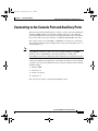
Connecting to the Console Port and Auxiliary Ports 3-14
PRP Console Port Signals 3-16
PRP Auxiliary Port Signals 3-17
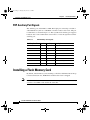
Installing a Flash Memory Card 3-17
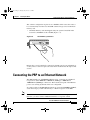
Connecting the PRP to an Ethernet Network 3-18
Connecting to an AC Power Source 3-23
Connecting to a DC Power Source 3-25
Powering on the Router for the First Time 3-28
External Network Interface 3-32
Manually Booting the System 3-32
CHAPTER
4
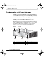
Troubleshooting the Installation 4-1
Identifying Startup Problems 4-2
Using the System LEDs to Troubleshoot 4-3
Problem-Solving with Subsystems 4-5
Troubleshooting an AC Power Subsystem 4-6
Troubleshooting the DC Power Subsystem 4-9
Troubleshooting the Processor Subsystem 4-13
Troubleshooting the RP 4-14
Troubleshooting the Line Cards 4-19
Troubleshooting the Cooling Subsystem 4-19
CHAPTER
5
Maintaining the Router 5-1
Tools and Equipment 5-2
Powering Off the Router 5-3
Removing and Installing the Front Cover 5-4
Cisco XR 12404 Router Installation Guide
OL-13830-02
vii
todd.book Page viii Tuesday, July 24, 2007 3:54 PM
Contents
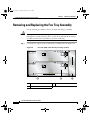
Removing and Replacing the Air Filter 5-7
Removing and Replacing the Fan Tray Assembly 5-10
Troubleshooting the Fan Tray Assembly Installation 5-12
Removing and Replacing an AC Power Entry Module 5-13
Troubleshooting an AC PEM Installation 5-15
Removing and Replacing a DC Power Entry Module 5-17
Troubleshooting the DC PEM Installation 5-20
Removing and Replacing a DC PDU 5-21
Troubleshooting the DC PDU Installation 5-27
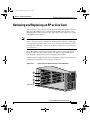
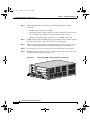
Removing and Replacing an RP or Line Card 5-29
Attaching the Cable-Management Bracket and Connecting Cables 5-32
Removing and Replacing a Consolidated Switch Fabric Card 5-35
Upgrading the RP and Line Card Memory 5-37
APPENDIX
A
Technical Specifications A-1
Product Architecture A-2
Specifications A-3
Compliance Information A-5
Regulatory, Compliance, and Safety Information A-8
Translated Safety Warnings and Agency Approvals A-8
Electromagnetic Compatibility Regulatory Statements A-8
INDEX
Cisco XR 12404 Router Installation Guide
viii
OL-13830-02
todd.book Page ix Tuesday, July 24, 2007 3:54 PM
About This Guide
Audience
The audience for the Cisco XR 12404 Router Installation Guide user
documentation are the people who will install and configure a
Cisco XR 12404 Router. The user typically has a substantial background in
installing and configuring router- and switch-based Internets but may or may not
have experience with Cisco products and supported protocols.
The reader of this documentation should be familiar with electronic circuitry and
wiring practices and have experience as an electronic or electromechanical
technician.
Purpose
This installation and configuration guide explains the hardware installation and
basic configuration procedures for a Cisco XR 12404 Router. It contains
procedures for installing the hardware, creating a basic configuration file, and
starting up the router.
Cisco XR 12404 Router Installation Guide
OL-13830-02
ix
todd.book Page x Tuesday, July 24, 2007 3:54 PM
About This Guide
Installation Guide Organization
Installation Guide Organization
The Cisco XR 12404 Router Installation Guide has the following chapters and
appendix; the paper version of this document may contain an index.
•
Chapter 1, “Cisco XR 12404 Router Overview”—Contains a high-level
system overview and physical description of the major components of a
Cisco XR 12404 Router including the power and cooling systems, the power
requirements, the Route Processor (RP) and the consolidated switch fabric
(CSF) card which contains the clock and scheduler, alarm and switch fabric
functions.
•
Chapter 2, “Preparing for Installation”—Contains safety, site requirements
for power, environmental safety, cabling, rack-mounting, electrostatic
discharge (ESD), the site log, and site preparation checklist.
•
Chapter 3, “Installing the Router”—Contains procedures for verifying the
Cisco XR 12404 Router installation, grounding, cable connection, AC-and
DC-power source and powering-up the router.
•
Chapter 4, “Troubleshooting the Installation”—Contains procedures for
identifying and solving problems that may occur during installation.
•
Chapter 5, “Maintaining the Router”—Contains safety at the field
replaceable unit (FRU) level, removal and replacement procedures for
field-replaceable units, FRU assemblies, and associated procedures to
troubleshoot and verify each FRU.
•
Appendix A, “Technical Specifications”—Contains Cisco XR 12404 Router
specifications.
•
Index—Contains a keyword and subject index of pertinent terms and
information.
Cisco XR 12404 Router Installation Guide
x
OL-13830-02
todd.book Page xi Tuesday, July 24, 2007 3:54 PM
About This Guide
Document Conventions
Document Conventions
This publication uses the following conventions:
•
The key combination Ctrl-z means hold down the Control key while you
press the z key.
Command descriptions use these conventions:
•
Examples that contain system prompts denote interactive sessions, indicating
the commands that you should enter at the prompt. The system prompt
indicates the current level of the EXEC command interpreter.
For example, the prompt router> indicates that you should be at the user
level, and the prompt router# indicates that you should be at the privileged
level. Access to the privileged level usually requires a password. Refer to the
related software configuration and reference documentation for additional
information.
•
Commands and keywords are in bold font.
•
Arguments for which you supply values are in italic font.
•
Elements in square brackets ([ ]) are optional.
•
Alternative but required keywords are grouped in braces ({ }) and separated
by vertical bars (|).
Examples use these conventions:
Caution
Note
•
Terminal sessions and sample console screen displays are in
•
Information you enter is in boldface
•
Nonprinting characters, such as passwords, are in angle brackets (< >).
•
Default responses to system prompts are in square brackets ([ ]).
•
Exclamation points (!) at the beginning of a line indicate a comment line.
screen
screen
font.
font.
Means reader be careful. You are capable of doing something that might result in
equipment damage or loss of data.
Means reader take note. Notes contain helpful suggestions or references to
materials not contained in this manual.
Cisco XR 12404 Router Installation Guide
OL-13830-02
xi
todd.book Page xii Tuesday, July 24, 2007 3:54 PM
About This Guide
Obtaining Documentation, Obtaining Support, and Security Guidelines
Timesaver
Warning
Means the described action saves time. You can save time by performing the
action described in the paragraph.
This warning symbol means danger. You are in a situation that could cause
bodily injury. Before you work on any equipment, be aware of the hazards
involved with electrical circuitry and be familiar with standard practices for
preventing accidents. To see translations of the warnings that appear in this
publication, refer to the Regulatory Compliance and Safety Information
document that accompanied this device.
Obtaining Documentation, Obtaining Support, and
Security Guidelines
For information on obtaining documentation, obtaining support, providing
documentation feedback, security guidelines, and recommended aliases and
general Cisco documents, see the monthly What’s New in Cisco Product
Documentation, which also lists all new and revised Cisco technical
documentation, at:
http://www.cisco.com/en/US/docs/general/whatsnew/whatsnew.html
Cisco XR 12404 Router Installation Guide
xii
OL-13830-02
todd.book Page 1 Tuesday, July 24, 2007 3:54 PM
CH A P T E R
1
Cisco XR 12404 Router Overview
This chapter provides an overview of the Cisco XR 12404 router. It contains
physical descriptions of the router hardware and major components, and
functional descriptions of hardware-related features.
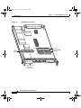
Router Overview
The Cisco XR 12404 router scales the Internet Service Provider edge from speeds
of T3/E3 (44.7/34.4 Mbps) up to OC-192/STM-64 or 10GE (10 Gbps).
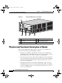
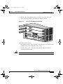
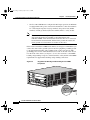
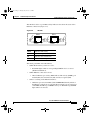
Figure 1-1 shows the PRP-2, consolidated switch fabric (CSF) card, and line card
locations of the Cisco XR 12404 router. Network interfaces reside on the line
cards that provide the connection between the router’s CSF and the external
networks. The bottom slot (labeled Fabric Alarm) is a dedicated slot for the
combined CSF card.
Note
Illustration is shown without the front door for clarity.
Cisco XR 12404 Router Installation Guide
OL-13830-02
1-1
todd.book Page 2 Tuesday, July 24, 2007 3:54 PM
Chapter 1
Cisco XR 12404 Router Overview
Physical and Functional Description of Router
Figure 1-1
Cisco XR 12404 Router—Front View
1
CLASS 1 LASER
LASERPRODUKT PRODUCT
PRODUIT LASER DER KLASSE 1
DE CLASSE 1
PRODUCTO LASER
DE CLASSE 1
CONNECTOR
TX
0
1
RX
2
3
EJ
EC
ACTIVE
CARRIER
T
SL
SL
-1
OT
-0
OT
RE
SE
RX PKT
T
X
AU
E
OL
NS
CO
CO
RJ
LIN
K
40C48/POS
-SR-SC
LL
RX
66275
CLEAN
WITH ALCOHOL
WIPES
BEFORE
CONNECTING
-45
TX
MI
CR
IT MA
IC
AL JO MINO
R
R
I
GIGABIT
ROUTE
PROCESSO
R
MBUS
ALARM FABRIC
FAIL
ENABLE
CONSOLI
2
3
DATED
4
SWITCH
FABRIC
5
1
Line card
4
CSF card
2
Line card
5
Rack mounting bracket
3
Route Processor
Physical and Functional Description of Router
The Cisco XR 12404 router supports up to 8 chassis in a one standard 7-foot
(2.15 meter) rack and has the following key features:
•
Route processor (PRP-2)—The primary route processor is installed in it’s
own dedicated slot. A redundant route processor can go in any line card slot.
See the “Route Processor” section on page 1-3 for information.
•
Line cards—The card cage contains 4 hot-swappable card slots. The router
can accommodate up to three OC-192 line cards (or 2 line cards if redundant
route processors are installed). See the “Supported Line Cards” section on
page 1-13 for information.
•
Consolidated switch fabric card (CSF)—Switch fabric, alarm, and clock
schedule functions are located on one board. The CSF card has a switching
capacity of 10 Gbps. See the “Consolidated Switch Fabric Card” section on
page 1-15 for information.
Cisco XR 12404 Router Installation Guide
1-2
OL-13830-02
todd.book Page 3 Tuesday, July 24, 2007 3:54 PM
Chapter 1
Cisco XR 12404 Router Overview
Route Processor
•
AC power entry module (PEM)—A customized and hot-swappable one-piece
unit. See the “Power Entry Modules” section on page 1-17 for information.
•
DC power entry module (PEM) and DC power distribution unit (PDU)—Two
pieces that can be removed as one unit or in separate pieces. See the “Power
Entry Modules” section on page 1-17 for information.
Note
When operating the router, both power module bays must have DC PEMs
and DC PDUs installed to ensure EMI compliance.
•
Fan tray assembly—Supplies cooling air to the router. See the “Fan Tray
Assembly” section on page 1-20 for information.
•
Cable management bracket used to neatly route line card cables. See the
“Cable Management System” section on page 1-22 for information.
•
Maintenance Bus—Controls all of the MBus modules in the system. See the
“Maintenance Bus” section on page 1-24 for information.
Route Processor
The route processor for the Cisco XR 12404 router is the Performance Route
Processor (PRP-2). For detailed information about the PRP-2, refer to the Cisco
document, Performance Route Processor Installation and Configuration Guide.
The PRP-2 performs the following primary functions:
•
Executes routing protocol stacks
•
Performs all protocol communications with other routers
•
Builds and distributes forwarding information to all line cards
•
Uploads the operating system software images to all installed line cards
during power-on
•
Provides out-of-band system console and auxiliary ports and an Ethernet port
for router configuration and maintenance
•
Monitors and manages the power and temperature of system components
such as line cards, power supplies, and fans
Cisco XR 12404 Router Installation Guide
OL-13830-02
1-3
todd.book Page 4 Tuesday, July 24, 2007 3:54 PM
Chapter 1
Cisco XR 12404 Router Overview
Route Processor
The Cisco PRP-2 delivers all these functions with enhanced performance and
capabilities. It also delivers the following feature enhancements (depending on
the software version running):
•
2 Ethernet management ports
•
Hard-drive support (optional part)
•
BITS input ports
•
1 GB compact image Flash memory support (optional part)
•
Memory scalability up to 4 GB
The PRP-2 communicates with the line cards either through the switch fabric or
through the MBus. The switch fabric connection is the main data path for routing
table distribution as well as for packets that are sent between the line cards and
the PRP-2. The MBus connection allows the PRP-2 to download a system
bootstrap image, collect or load diagnostic information, and perform general,
internal system maintenance operations.
The PRP-2 can be designated as either the Designated System Controller (DSC)
or the Secure Domain router (SDR).
The Designated System Controller (DSC) performs the following functions:
•
Implements control plane operations for the chassis
•
Monitors temperature and voltage
•
Monitors line cards
•
On boot up, the first card to become active is designated as the DSC.
The Secure Domain Router (SDR) controls domain security features independent
of any other SDRs on the network.
Cisco XR 12404 Router Installation Guide
1-4
OL-13830-02
todd.book Page 5 Tuesday, July 24, 2007 3:54 PM
Chapter 1
Cisco XR 12404 Router Overview
Route Processor
Performance Route Processor Overview
The performance route processor (PRP) uses a Motorola PowerPC 7450 CPU that
runs at an external bus clock speed of 133 MHz and has an internal clock speed
of 667 MHz.
Figure 1-2 identifies the slots, ports, and LEDs on the PRP front panel.
Performance Route Processor Front Panel
AUX
75041
TX
EN
TX
EN
LIN
K
PRIMARY
T
SE
RE
PRIMARY
CONSOLE
RX
ETH 1
RX
SL SL
OT OT
-0 -1
EJ
EC
T
ETH 0
LIN
K
Figure 1-2
PERFORMANCE ROUTE PROCESSOR 1 (PRP-1)
1
PCMCIA flash disk slots (shown with cover in 4
place) and slot LEDs
2
RJ-45 Ethernet ports and data status LEDs
5
Reset button
3
Auxiliary serial port
6
Alphanumeric messages
Console serial port
PRP PCMCIA Card Slots and Status LEDs
Two PCMCIA card slots (slot 0 and slot 1) provide the PRP with additional flash
memory capacity. All combinations of different flash devices are supported by the
PRP. You can use ATA flash disks, Type 1 or Type 2 linear flash memory cards,
or a combination of the two.
Note
The PRP only supports +5.2 VDC flash memory devices. It does not support
+3.3 VDC PCMCIA devices.
Status LEDs (Slot-0 / Slot-1) indicate when the flash memory card in that slot is
accessed (see Figure 1-2). Each slot has an eject button (located behind the cover)
to remove a flash card from the slot.
Cisco XR 12404 Router Installation Guide
OL-13830-02
1-5
todd.book Page 6 Tuesday, July 24, 2007 3:54 PM
Chapter 1
Cisco XR 12404 Router Overview
Route Processor
PRP Ethernet Ports and Status LEDs
The PRP has two 8-pin media-dependent interface (MDI) RJ-45 ports for either
IEEE 802.3 10BASE-T (10 Mbps) or IEEE 802.3u 100BASE-TX (100 Mbps)
Ethernet connections. These ports are labeled ETH 0 and ETH 1.
The transmission speed of the Ethernet port is not user-configurable. You set the
speed through an autosensing scheme on the PRP which is determined by the
network that the Ethernet port is connected to. However, even at an autosensed
data transmission rate of 100 Mbps, the Ethernet port can only provide a usable
bandwidth of substantially less than 100 Mbps. You can expect a maximum usable
bandwidth of approximately 20 Mbps when using an Ethernet connection.
The following LEDs on the front panel indicate traffic status and port selection
(Figure 1-3):
•
LINK, EN, TX, RX—Indicate link activity (LINK), port enabled (EN), data
transmission (TX), and data reception (RX).
•
PRIMARY—Indicates which Ethernet port is selected (ETH 0 or ETH 1).
Because both ports are supported on the PRP, ETH 0 is always on. ETH 1
lights when it is selected.
Port Activity LEDs—Partial Front Panel
TX
EN
TX
PRIMARY
70693
PRIMARY
LIN
K
EN
SL
RX
RX
ETH 1
S
OT LOT
-0 -1
ETH 0
K
Figure 1-3
LIN
Note
Cisco XR 12404 Router Installation Guide
1-6
OL-13830-02
todd.book Page 7 Tuesday, July 24, 2007 3:54 PM
Chapter 1
Cisco XR 12404 Router Overview
Route Processor
PRP Auxiliary and Console Ports
The auxiliary and console ports on the PRP are EIA/TIA-232 (also known as
RS-232) asynchronous serial ports. These ports connect external devices to
monitor and manage the system.
•
The auxiliary port—A (male) plug that provides a data terminal equipment
(DTE) interface. The auxiliary port supports flow control and is often used to
connect a modem, a channel service unit (CSU), or other optional equipment
for Telnet management.
•
The console port—A (female) receptacle that provides a data
circuit-terminating equipment (DCE) interface for connecting a console
terminal.
PRP Reset Switch
Access to the (soft) reset switch is through a small opening in the PRP front panel
(see Figure 1-2). To press the switch, insert a paper clip or similar small pointed
object into the opening.
Caution
The reset switch is not a mechanism for resetting the PRP and reloading the
Cisco IOS image. It is intended for software development use only. To prevent
system problems or loss of data, use the reset switch only on the advice of Cisco
service personnel.
Pressing the reset switch causes a nonmaskable interrupt (NMI) and places the
PRP in ROM monitor mode. When the PRP enters ROM monitor mode, its
behavior depends on the setting of the PRP software configuration register. For
example, if the boot field of the software configuration register is set to:
•
0x0—The PRP remains at the ROM monitor prompt (rommon>) and waits for
a user command to boot the system manually.
•
0x1—The system automatically boots the first Cisco IOS image found in
flash memory on the PRP.
Cisco XR 12404 Router Installation Guide
OL-13830-02
1-7
todd.book Page 8 Tuesday, July 24, 2007 3:54 PM
Chapter 1
Cisco XR 12404 Router Overview
Route Processor
PRP Alphanumeric Message Displays
The alphanumeric message displays are organized in two rows of four LED
characters each (Figure 1-4).
Figure 1-4
Alphanumeric Message Displays—Partial Front Panel
PROCESSOR
Upper alphanumeric
LED display (four digits)
H10780
Lower alphanumeric
LED display (four digits)
The alphanumeric message displays show router status messages during the boot
process, and after the boot process is complete.
•
During the boot process, the message displays are controlled directly by the
MBus module.
•
After the boot process, the message displays are controlled by Cisco IOS XR
software (through the MBus).
The alphanumeric message displays also provide information about different
levels of system operation, including the status of the PRP, router error messages,
and user-defined status and error messages
Note
A list of all system and error messages appears in the Cisco IOS System Error
Messages publication.
Cisco XR 12404 Router Installation Guide
1-8
OL-13830-02
todd.book Page 9 Tuesday, July 24, 2007 3:54 PM
Chapter 1
Cisco XR 12404 Router Overview
Route Processor
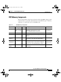
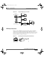
PRP Memory Components
This section describes various types of memory used on the PRP to support router
functions. Table 1-1 provides a quick reference of the different types of memory,
and Figure 1-5 shows the location on the PRP board.
Table 1-1
Type
PRP Memory Components
Size
Quantity
MB1,
Description
Location
SDRAM
512
1 or 2
1 GB, or 2 GB
Uses 512 MB or 1 GB DIMMs (based on
SDRAM configuration) for main
Cisco IOS XR software functions
U15 (bank 1)
U18 (bank 2)
SRAM
2 MB (fixed)
—
Secondary CPU cache memory functions
—
NVRAM
2 MB (fixed)
—
System configuration files, register settings, —
and logs
Flash
memory
64 MB SIMM 1
Cisco IOS XR boot image (bootflash), crash P3
information, and other user-defined files
Flash disk
(PCMCIA)
64 MB1
1 or 2
Cisco IOS XR software images, system
configuration files, and other user-defined
files on one or two Flash memory cards
Flash boot
ROM
512 KB
1
Flash EPROM for the ROM monitor program —
boot image
Flash memory
card slot 0 and
slot 1
1. Default shipping configuration.
Cisco XR 12404 Router Installation Guide
OL-13830-02
1-9
todd.book Page 10 Tuesday, July 24, 2007 3:54 PM
Chapter 1
Cisco XR 12404 Router Overview
Route Processor
Figure 1-5
PRP Memory Locations
U18
Flash
SIMM
Bank 2
DRAM DIMMs
Bank 1
P3
U15
EC
T
ETH 0
ETH 1
-1
OT
SL
-0
OT
EN
LIN
PCMCIA slot-1
and slot-2
(behind cover)
K
TX
EN
PRIMARY
LIN
K
CONSOLE
TX
T
SE
RE
PRIMARY
AUX
RX
RX
SL
PERFORMANCE ROUTE PROCESSOR 1 (PRP-1)
129256
EJ
Cisco XR 12404 Router Installation Guide
1-10
OL-13830-02
todd.book Page 11 Tuesday, July 24, 2007 3:54 PM
Chapter 1
Cisco XR 12404 Router Overview
Route Processor
PRP SDRAM
The PRP uses Error Checking and Correction (ECC) Synchronized Dynamic
Random Access Memory (SDRAM) to store routing tables, protocols, network
accounting applications, and to run Cisco IOS software.
Table 1-2 lists the DRAM configurations for the PRP. If you are using:
•
One DIMM—Bank 1 (U15) must be populated first.
•
Two DIMMs—You cannot mix memory sizes; both banks must contain the
same size DIMM.
Table 1-2
Total
SDRAM
PRP DRAM Configurations
SDRAM Sockets
Number of DIMMs
U15 (bank 1)
U18 (bank 2)
One 512 MB DIMM
or
Two 256 MB DIMMs
1 GB
U15 (bank 1)
U18 (bank 2)
One 1 GB DIMM
or
Two 512 MB DIMMs
2 GB
U15 (bank 1)
U18 (bank 2)
Two 1 GB DIMMs
512
MB1
1. Default shipping configuration.
Caution
DRAM DIMMs must be 3.3-volt, 60-nanosecond devices only. Do not attempt to
install other devices in the DIMM sockets. To prevent memory problems, use the
Cisco approved memory products listed in Table 1-2.
PRP SRAM
Static Random Access Memory (SRAM) provides 2 MB of secondary CPU cache
memory. Its principal function is to act as a staging area for routing table updates,
and for information sent to and received from the line cards. SRAM is not
user-configurable and cannot be upgraded in the field.
Cisco XR 12404 Router Installation Guide
OL-13830-02
1-11
todd.book Page 12 Tuesday, July 24, 2007 3:54 PM
Chapter 1
Cisco XR 12404 Router Overview
Route Processor
PRP NVRAM
Non-volatile Random Access Memory (NVRAM) provides 2 MB of memory for
system configuration files, software register settings, and environmental
monitoring logs. Built-in lithium batteries retain the contents of NVRAM for a
minimum of 5 years. NVRAM is not user configurable and cannot be upgraded in
the field.
PRP Flash Memory
Use flash memory to store multiple Cisco IOS XR software and microcode
images that you can use to operate the router. You can download new images to
flash memory over the network (or from a local server) to replace an existing
image, or to add it as an additional image. The router can be booted (manually or
automatically) from any of the stored images in flash memory.
Flash memory also functions as a Trivial File Transfer Protocol (TFTP) server to
allow other servers to boot remotely from the stored images, or to copy them into
their own flash memory.
The system uses two types of flash memory:
•
Onboard flash memory (called bootflash)—Contains the Cisco IOS boot
image
•
Flash memory disks (or cards)—Contain the Cisco IOS software image
Table 1-3 lists supported flash disk sizes and Cisco part numbers.
Table 1-3
Supported Flash Disk Sizes
Flash Disk Size1
Part Number
64 MB2
MEM-12KRP-FD64=
128 MB
MEM-12KRP-FD128=
1 GB
MEM-12KRP-FD1G=
1. Standard Type 1 and Type 2 linear flash memory cards also are supported,
although they may not have the capacity to meet the configuration
requirements of your system.
2. Default shipping configuration.
Cisco XR 12404 Router Installation Guide
1-12
OL-13830-02
todd.book Page 13 Tuesday, July 24, 2007 3:54 PM
Chapter 1
Cisco XR 12404 Router Overview
Supported Line Cards
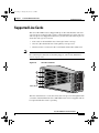
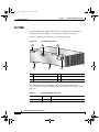
Supported Line Cards
The Cisco XR 12404 router is shipped with up to three installed line cards and
one route processor that provide a variety of network media types. Line card slots
and route processors shipped from the factory are based on your order. Figure 1-6
shows the card cage slot locations:
Note
•
Line cards can be installed in slots 1 through 3 in the card cage.
•
Slot zero (0) is the default slot for the primary route processor.
•
The bottom slot is reserved for the consolidated switch fabric (CSF) card.
Refer to the software release notes for a current list of supported line cards (see
the “Obtaining Documentation, Obtaining Support, and Security Guidelines”
section on page -xii).
Figure 1-6
Card Slot Locations
3
2
1
66252
0
Fabric Alarm
The line cards interface to each other, and to the route processor through the CSF
card. Line cards installed in the Cisco XR 12404 router are hot swappable and can
be replaced while the router is operating.
Cisco XR 12404 Router Installation Guide
OL-13830-02
1-13
todd.book Page 14 Tuesday, July 24, 2007 3:54 PM
Chapter 1
Cisco XR 12404 Router Overview
Supported Line Cards
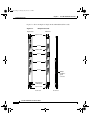
Figure 1-7 shows examples of single-mode and multimode line cards.
Figure 1-7
Sample Line Cards
Multimode
Single Mode
Ejector lever
0
ER
VE I KT
TI RR P
AC CA RX
ER
VE I KT
TI RR P
AC CA RX
Status LEDs
1
1
Port 1
ER
VE I KT
TI RR P
AC CA RX
ER
VE I KT
TI RR P
AC CA RX
2
2
Port 2
ER
VE I KT
TI RR P
AC CA RX
ER
VE I KT
TI RR P
AC CA RX
3
3
Port 3
ER
VE I KT
TI RR P
AC CA RX
ER
VE I KT
TI RR P
AC CA RX
Alphanumeric
LED display
Ejector lever
Front view
Q OC-3/STM-1 MM POS
Q OC-3/STM-1 SM IR POS
160-pin
backplane
signal
connector
H10781
0
Port 0
Rear view
Cisco XR 12404 Router Installation Guide
1-14
OL-13830-02
todd.book Page 15 Tuesday, July 24, 2007 3:54 PM
Chapter 1
Cisco XR 12404 Router Overview
Consolidated Switch Fabric Card
Consolidated Switch Fabric Card
The Cisco XR 12404 router CSF card contains the following functionality:
•
Alarm notification and power source monitoring
•
Switch fabric synchronized speed interconnections
•
Clock and scheduler synchronization signaling
Alarm Functionality
The CSF card alarm functionality provides visual alarm notification of a fault
condition. The alarm card function indicates the following condition.
•
Alarm status
•
CSF MBus
•
Alarm MBus status
•
Fan fault monitoring
•
AC or DC power source status
•
DC PEM status
– The 5V MBus power supply has been integrated onto the CSF permitting
the use of generic PEMs in the chassis. The Cisco XR 12404 router can
monitor for the PEM for these conditions:
•
The operational status
•
Output voltage
•
Output current.
•
Alarm Output Function
– The alarm output function is controlled by the software on the route
processor. When a signal is received from the route processor the alarm
MBus module on the CSF card activates specific LEDs to signal a
condition that is critical, major, or minor.
Cisco XR 12404 Router Installation Guide
OL-13830-02
1-15
todd.book Page 16 Tuesday, July 24, 2007 3:54 PM
Chapter 1
Cisco XR 12404 Router Overview
Consolidated Switch Fabric Card
•
LEDs
– LEDs alert you to a condition in the router. The determination of a
critical, major, or minor alarm condition is designed into Cisco IOS XR
software running on your route processor.
•
CSF MBus Status
– Drivers are provided for MBus OK and Fail indication.
•
The 5V MBus power supply
– Consists of a 100 W DC-DC converter.
•
Alarm Status
– The Alarm output function consists of a group of LEDs and their
associated drivers connected to an output port on the alarm MBus
module. As directed by the software on the route processor, the alarm
MBus module on the CSF card activates specific LEDs. The software
which drives these LEDs divides them into three levels, Critical, Major,
and Minor. The classification of a critical, major, or minor alarm is
determined by Cisco IOS XR software running on the route processor.
Each of the three LEDs is a dual LED (for failure redundancy).
– The OK/Fail pair of LEDs indicate the status of the alarm MBus:
Green indicates that the alarm MBus module is operating properly.
Amber Fail indicates that the alarm MBus has detected an error in itself
or with the MBus module.
Power Source Monitoring
The alarm MBus monitors the power supply and signals when there is a condition
outside the normal range of operation.
•
Power source voltage is not being provided to a component
•
A fault exist in the power source or PEM
•
A voltage monitor signal is outside the allowable range
•
The current monitor signal is outside the allowable range
Cisco XR 12404 Router Installation Guide
1-16
OL-13830-02
todd.book Page 17 Tuesday, July 24, 2007 3:54 PM
Chapter 1
Cisco XR 12404 Router Overview
Power Entry Modules
Switch Fabric Functionality
Switch fabric circuitry provides up to 40 Gbps (full duplex) of synchronized speed
interconnections that carries user traffic between line cards or between the route
processor and the line cards.
Clock and Scheduler Functionality
The fabric card generates and distributes system-wide clock and cell time
synchronization signaling. System clock generation is delivered to the system
through the backplane and local clock functions are derived from the system
clock.
•
System Clock—The system clock synchronizes data transfers between line
cards or between the route processor and a line card through the CSF. The
system clock signal is sent to all line cards and the route processor.
•
Scheduler—The scheduler handles requests from the line cards for access to
the CSF. When the scheduler receives a request from a line card for CSF
access, the scheduler determines when to allow the line card access to the
CSF.
Power Entry Modules
The Cisco XR 12404 router chassis supports two hot swappable AC or DC PEMs.
The router must be populated with 2 PEMs to meet EMI standards.
Caution
Do not mix PEM types in the router. PEMs must be the same type; either both
AC PEMs, or both DC PEMs and PDUs.
Cisco XR 12404 Router Installation Guide
OL-13830-02
1-17
todd.book Page 18 Tuesday, July 24, 2007 3:54 PM
Chapter 1
Cisco XR 12404 Router Overview
Power Entry Modules
AC PEMs
Each AC PEM converts 200 to 240 VAC into -48 VDC, which is distributed
through the chassis backplane to all cards, RPs, and the fan assembly.
Figure 1-8 identifies the components of an AC power supply.
Figure 1-8
1
AC PEM Components
2
3
INPUT
OK
INPUT
100-240
V
12A
OUTPUT
OUT
OK
PUT
FAIL
66289
50/80HZ
6
5
4
1
AC PEM finger grips
4
Power cord receptacle
2
On/Off switch
5
Status LEDs
3
Bail latch
6
Captive screws
The status LEDs on the AC PEM provide information about the current
operational status of the power supply. Table 1-4 summarizes the function of these
indicators.
Table 1-4
AC-Input PEM LED Indicators
LED Label
Color
Function
OUTPUT OK
Green
PEM is powered on and operating normally.
Cisco XR 12404 Router Installation Guide
1-18
OL-13830-02
todd.book Page 19 Tuesday, July 24, 2007 3:54 PM
Chapter 1
Cisco XR 12404 Router Overview
Power Entry Modules
Table 1-4
AC-Input PEM LED Indicators (continued)
LED Label
Color
Function
Input OK
Green
The AC power source is present and operating
within the specified limit.
Output Fail
Amber
Indicates a failure in the PEM.
DC PEMs
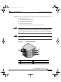
Each DC PEM operates from a nominal source DC voltage of -48 to -60 VDC and
requires a dedicated 60 amp service.
Figure 1-9 identifies the components of a DC power supply.
Figure 1-9
DC PEM and PDU Components
1
2
3
INP UT
– 48/ 60V
35A
OUTPUT
FAIL
66295
INPUT
OUTPUT
OK
OK
5
7
3
6
4
1
DC PDU
5
On/Off switch
2
DC PEM
6
PDU captive screws
3
PEM captive screws
7
PDU terminal block
4
Status LEDs
Cisco XR 12404 Router Installation Guide
OL-13830-02
1-19
todd.book Page 20 Tuesday, July 24, 2007 3:54 PM
Chapter 1
Cisco XR 12404 Router Overview
Fan Tray Assembly
The status LEDs on the DC PEM provide information about the current
operational status of the power supply. Table 1-5 summarizes the function of these
indicators.
Table 1-5
DC-Input PEM LED Indicators
LED Label
Color
Function
Output OK
Green
PEM is powered on and operating normally.
Input OK
Green
DC power is present at the PEM input and
within the specified limits.
Output Fail
Amber
Indicates a failure in the PEM.
Power Distribution
The backplane distributes power through the Cisco XR 12404 router and to all
cards in the card cage. The PEM converts AC power source into –48 VDC. When
directed by the route processor or by MBus software, the MBus module turns on
the DC-DC converter; the –48 VDC is converted into +2.5 VDC, +3.3 VDC and
+5 VDC for all internal voltages required by the cards.
Power for the fan tray assembly is supplied directly from the backplane. An
internal fan tray assembly controller card converts –48 VDC into DC voltage that
powers the fans.
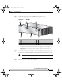
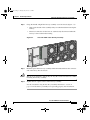
Fan Tray Assembly
The Cisco XR 12404 router is equipped with a fan tray assembly located at the
side of the chassis. The fan tray assembly maintains acceptable operating
temperatures for the internal components by drawing cooling air across the card
cage.
Cisco XR 12404 Router Installation Guide
1-20
OL-13830-02
todd.book Page 21 Tuesday, July 24, 2007 3:54 PM
Chapter 1
Cisco XR 12404 Router Overview
Fan Tray Assembly
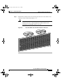
The fan tray assembly is a sheet metal enclosure containing 7 fans and 2 fan
controller cards (Figure 1-10).
Warning
Exhaust from other equipment vented directly into the Cisco XR 12404 router air
inlet can cause an over-heat condition. Install the router so that it is protected
from a direct flow of hot air from other equipment.
Fan Tray Assembly
66250
Figure 1-10
The fan tray assembly draws room air in through the air filter, across the card cage
and out through exhaust vents located on the side of the chassis.
Note
Warm air exits at the side of the chassis. Allow sufficient air flow by maintaining
6 inches (15.24 CM) of clearance at both the inlet and exhaust openings on the
chassis.
A fan tray assembly controller card monitors the operation of the 7 fans.
Cisco XR 12404 Router Installation Guide
OL-13830-02
1-21
todd.book Page 22 Tuesday, July 24, 2007 3:54 PM
Chapter 1
Cisco XR 12404 Router Overview
Cable Management System
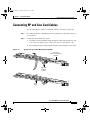
Cable Management System
The Cisco XR 12404 router is set up with two types of cable management
systems:
•
Figure 1-11
Line card cable-management bracket (Figure 1-11)—Attached to each line
card and routes the line card cables to the chassis cable management bracket.
These brackets keep the cables free of sharp bends and out of the way.
RP and Line Card Cable-Management Brackets
Line card
cable management
bracket
E R L
TIV RIE EL
AC CAR RX C
0
E R L
TIV RIE EL
AC CAR RX C
0
E R L
TIV RIE EL
AC CAR RX C
0
E R L
TIV RIE EL
AC CAR RX C
OC-12/
STM-4
POS
Network
interface
cables
0
E R L
TIV RIE EL
AC CAR RX C
0
E R L
TIV RIE EL
AC CAR RX C
0
Velcro
strap
E R L
TIV RIE EL
AC CAR RX C
57803
E R L
TIV RIE EL
AC CAR RX C
OC-12/
STM-4
POS
Cisco XR 12404 Router Installation Guide
1-22
OL-13830-02
todd.book Page 23 Tuesday, July 24, 2007 3:54 PM
Chapter 1
Cisco XR 12404 Router Overview
Cable Management System
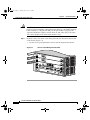
Chassis cable-management bracket (see Figure 1-12)—Attached to the
chassis and routes the line card cables away from the chassis.
Figure 1-12
Chassis Cable Management Bracket
CLEAN
CONNEC
WITH ALCOHOL
WIPES
BEFORE
CONNECTI
NG
TOR
CLASS 1 LASER
LASERPRODUK PRODUCT
PRODUIT LASERT DER KLASSE 1
DE CLASSE
1
PRODUCTO LASER
DE CLASSE 1
TX
0
1
RX
2
3
EJE
CT
ACTIVE
CARRIER
T-1
SLO 0
TSLO
RE
SE
RX PKT
T
X
AU
OLE
NS
CO
CO
LL
40C48/P
OS-
RX
RJ-
K
LIN
SR-SC
45
66276
•
TX
MII
GIGABI
T ROUTE
CR
IT M
IC A M
AL JO IN
R OR
PROCES
SOR
MBUS
ALARM FABRIC
FAIL
ENABLE
CONSO
LIDATE
D SW
ITCH FAB
RIC
Cable-management systems:
Caution
•
Organize the interface cables on the line cards, route processor, and clock and
scheduler cards as they enter and exit the system.
•
Consists of two parts, a card cable-management bracket and a chassis
cable-management bracket.
Excessive bending in an interface cable can cause performance degradation.
Cisco XR 12404 Router Installation Guide
OL-13830-02
1-23
todd.book Page 24 Tuesday, July 24, 2007 3:54 PM
Chapter 1
Cisco XR 12404 Router Overview
Maintenance Bus
Maintenance Bus
The Cisco XR 12404 router maintenance bus and MBus modules manage all of
the maintenance functions of the system. The MBus consists of two separate
busses (providing MBus redundancy). Each MBus is linked to all of the following.
•
Line cards
•
Route Processor
•
CSF card
The MBus module located on each component, communicates over the MBus and
is powered by +5 VDC directly from the fabric card. The MBus performs the
functions of power-on/off control for each component, component (device)
discovery, code download, diagnostics, and environmental monitoring and
alarms.
Power-On/Off Control
Each MBus module directly controls the DC-to-DC converters on the component
it is mounted on based on commands the component receives from its on-board
EPROM and from the route processor. Each MBus module is tied directly to
+5 VDC from the consolidated fabric card.
When power is applied to the Cisco XR 12404 router, all MBus modules
immediately power on. The MBus modules on the route processor and CSF card
immediately turn on the DC-to-DC converter, powering up the respective card.
The line card MBus module waits to power on the line card until it receives a
command from the route processor.
Component Discovery
The route processor can determine the system configuration using the MBus. A
message is sent from the route processor over the MBus requesting all installed
devices to identify themselves. The response back provides component type, line
card slot number, and CSF card slot number.
Cisco XR 12404 Router Installation Guide
1-24
OL-13830-02
todd.book Page 25 Tuesday, July 24, 2007 3:54 PM
Chapter 1
Cisco XR 12404 Router Overview
Maintenance Bus
Code Download
A portion of the line card operating software can be downloaded from the route
processor to the line card over the MBus. Because the MBus is relatively slow
compared to the CSF, only enough code is downloaded to the line card for it to
access the CSF and complete the download process.
Diagnostics
The diagnostic software image is downloaded from the route processor to the line
card during the test sequence.
Environmental Monitoring and Alarms
The MBus module on each component monitors that component’s environment as
follows.
•
Line cards and the route processor are monitored for temperature by two
temperature sensors mounted on each card. The MBus module makes voltage
monitoring through software; for example the +2.5 VDC, +3.3 VDC, and
+5 VDC DC-to-DC converters.
•
The CSF card is monitored for temperature by two temperature sensors
mounted on the card. The MBus module performs voltage monitoring through
software (for example, the +2.5 VDC and +3.3 VDC).
•
Voltage monitoring the for +5 VDC, for example; is made by the alarm MBus
module on the CSF card.
•
Environmental monitoring includes voltage and current monitoring,
temperature monitoring, and sensing for fan power and RPM.
Cisco XR 12404 Router Installation Guide
OL-13830-02
1-25
todd.book Page 26 Tuesday, July 24, 2007 3:54 PM
Chapter 1
Cisco XR 12404 Router Overview
Maintenance Bus
Cisco XR 12404 Router Installation Guide
1-26
OL-13830-02
todd.book Page 1 Tuesday, July 24, 2007 3:54 PM
CH A P T E R
2
Preparing for Installation
This chapter provides specific information about preparing your site for the
installation of the Cisco XR 12404 Router. Included in this chapter are:
•
Tools and Equipment, page 2-2
•
Safety and Compliance, page 2-2
•
Safety with Electricity, page 2-8
•
Installation Site Requirements, page 2-8
•
Unpacking and Repacking the Cisco XR 12404 Router, page 2-16
•
Transporting a Cisco XR 12000 Series Router, page 2-17
•
Site Preparation Checklist, page 2-17
Before installing the Cisco XR 12404 Router, you should consider the following:
•
Power and cabling requirements that must be in place at your installation site
•
Equipment you will need to install the router
•
Environmental conditions your installation site must meet to maintain normal
operation.
Note
Do not unpack the router until you are ready to install it.
Cisco XR 12404 Router Installation Guide
OL-13830-02
2-1
todd.book Page 2 Tuesday, July 24, 2007 3:54 PM
Chapter 2
Preparing for Installation
Tools and Equipment
Tools and Equipment
The Cisco XR 12404 Router is designed to be installed with a minimum number
of tools. The following tools are required.
•
1/4-inch flat-blade screwdriver
•
3/16-inch flat-blade screwdriver
•
9/16-inch wrench
•
10-mm wrench (either open-end or socket)
•
2-mm allen wrench
•
ESD-preventive wrist or ankle strap
•
Antistatic mat
•
Tape measure
•
Wire cutters
•
Pliers
Safety and Compliance
The following guidelines will help to ensure your safety and protect the
equipment. This list is not inclusive of all potentially hazardous situations, so be
alert.
•
General Safety Guidelines, page 2-3
•
Preventing Electrostatic Discharge Damage, page 2-4
•
Laser Safety, page 2-6
•
Laser Safety, page 2-6
•
Lifting Guidelines, page 2-6
Cisco XR 12404 Router Installation Guide
2-2
OL-13830-02
todd.book Page 3 Tuesday, July 24, 2007 3:54 PM
Chapter 2
Preparing for Installation
Safety and Compliance
General Safety Guidelines
The following are some general safety guidelines you should be aware of when
installing or maintaining the Cisco XR 12404 Router.
•
Never attempt to lift an object that might be too heavy for you to lift by
yourself.
•
Always disconnect the power source and unplug all power cables before
lifting, moving or working on the router.
•
Keep the work area clear and dust free during and after installation.
•
Keep tools and router components away from walk areas.
•
Do not wear loose clothing, jewelry (including rings and chains), or other
items that could get caught in the router.
•
Fasten your tie or scarf and sleeves.
•
Cisco equipment operates safely when it is used in accordance with its
electrical ratings and product usage instructions.
•
Do not work alone if potentially hazardous conditions exist.
•
Always unplug the power cables when performing maintenance or working
on the router, unless the replacement part is capable of online insertion and
removal, hot swappable.
•
The installation of the router should be in compliance with national and local
electrical codes: in the United States, National Fire Protection Association
(NFPA) 70, United States National Electrical Code; in Canada, Canadian
Electrical Code, part I, CSA C22.1; in other countries, International
Electrotechnical Commission (IEC) 364, part 1 through part 7.
•
Before installing, configuring, or maintaining the router, review the safety
warnings listed in the document Regulatory Compliance and Safety
Information for the Cisco XR 12000 Series Routers).
•
A Cisco XR 12404 Router configured with the AC power entry module
(PEM) are shipped with a three-wire electrical grounding-type plug that will
only fit into a grounding-type power outlet. This is a safety feature. The
equipment grounding should be in accordance with local and national
electrical codes.
Cisco XR 12404 Router Installation Guide
OL-13830-02
2-3
todd.book Page 4 Tuesday, July 24, 2007 3:54 PM
Chapter 2
Preparing for Installation
Safety and Compliance
•
A Cisco XR 12404 Router configured with a DC PEM requires a dedicated
35–Amp DC circuit breaker for the DC power source. This circuit breaker
should protect against short-circuit and overcurrent faults in accordance with
United States National Electrical Code NFPA 70 (United States), Canadian
Electrical Code, part I, CSA C22.1; CSA C22.2 No. 0 (Canada) and IEC 364
(other countries).
•
Only a DC power source that complies with the safety extra-low voltage
(SELV) requirements in UL60950, CSA 60950, EN60950, and IEC 60950
can be connected to a Cisco XR 12404 Router DC PEM.
•
A Cisco XR 12404 Router configured with a DC PEM is to be installed in a
restricted access area and in accordance with Articles 110–18, 110–26, and
110–27 of the National Electric Code, ANSI/NFPA 70.
•
A Cisco XR 12404 Router configured with a DC power distribution unit
(PDU) shall have a readily accessible disconnect device incorporated in the
fixed wiring.
Compliance and Safety Information
The Cisco XR 12404 Router is designed to meet the regulatory compliance and
safety approval requirements. Refer to the Regulatory Compliance and Safety
Information for the Cisco XR 12000 Series Routers.
Preventing Electrostatic Discharge Damage
Electrostatic discharge (ESD) damage to circuit boards can occur if they are
handled improperly. Such mishandling can result in intermittent or complete
failures of the board.
When handling circuit boards, observe the following guidelines to prevent ESD
damage.
•
Always use an ESD-preventive ankle or wrist strap and ensure that the strap
makes adequate contact with your skin.
•
The ankle or wrist strap protects equipment from ESD voltages on the body
only; ESD voltages on clothing can still cause damage to electronic
components.
Cisco XR 12404 Router Installation Guide
2-4
OL-13830-02
todd.book Page 5 Tuesday, July 24, 2007 3:54 PM
Chapter 2
Preparing for Installation
Safety and Compliance
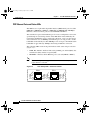
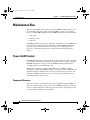
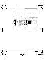
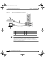
Attaching an ESD-Preventive Strap
Attach an ESD antistatic strap to your body and to an open metal part of the
chassis on the Cisco XR 12404 Router (Figure 2-1).
Figure 2-1
CONNECTOR
CLASS 1 LASER
LASERPRODUKT PRODUCT
PRODUIT LASER DER KLASSE 1
DE CLASSE 1
PRODUCTO LASER
DE CLASSE 1
TX
0
1
RX
2
3
EJ
EC
ACTIVE
CARRIER
T
SL
SL
-1
OT
-0
OT
RE
SE
RX PKT
T
X
AU
E
OL
NS
CO
CO
RX
RJ
LIN
K
40C48/POS
-SR-SC
LL
-45
66273
CLEAN
WITH ALCOHOL
WIPES
BEFORE
CONNECTING
Attaching an ESD-Preventive Strap to the Cisco XR 12404
Router Chassis
TX
MI
CR
IT MA
IC
AL JO MINO
R
R
I
GIGABIT
ROUTE
PROCESSO
R
MBUS
ALARM FABRIC
FAIL
ENABLE
CONSOLI
Caution
DATED
SWITCH
FABRIC
Periodically check the resistance value of the antistatic ankle or wrist strap. The
resistance measurement should be between 1 and 10 megohms.
Cisco XR 12404 Router Installation Guide
OL-13830-02
2-5
todd.book Page 6 Tuesday, July 24, 2007 3:54 PM
Chapter 2
Preparing for Installation
Safety and Compliance
Laser Safety
Single-mode style line cards for the Cisco XR 12404 Router are equipped with
lasers, which emit invisible radiation. Do not stare into open line card ports.
Warning
Avoid exposure to laser radiation. Do not stare into an open apertures, because
invisible laser radiation may be emitted from the aperture when a cable is not
inserted in the port.
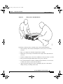
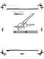
Lifting Guidelines
A fully configured Cisco XR 12404 Router weighs approximately 100 pounds
(45.36 kg). Before you install the router, ensure that your site is properly prepared
so you can avoid having to move the router later to accommodate power source
and network connections (Figure 2-2).
Cisco XR 12404 Router Installation Guide
2-6
OL-13830-02
todd.book Page 7 Tuesday, July 24, 2007 3:54 PM
Chapter 2
Preparing for Installation
Safety and Compliance
Figure 2-2
Lifting a Cisco XR 12404 Router
CLEAN
CONNECTOR
WITH ALCOHOL
WIPES
BEFORE
CONNECTING
CLASS 1 LASER
LASERPRODUKT PRODUCT
PRODUIT LASER DER KLASSE 1
DE CLASSE
1
PRODUCTO LASER
DE CLASSE 1
TX
0
1
RX
2
3
ACTIVE
CARRIER
T
EJEC
-1
SLOT
-0
SLOT
RX PKT
ET
RES
AUX
CON
SOL
40C48/PO
S-SR-SC
L
COL RX
E
5
RJ-4
LINK
TX
MII
CRIT
ICALMAJ
ORMINOR
GIGABIT
ROUTE
PROCESSO
R
MBUS
ALARM FABRIC
FAIL
ENABLE
IDATED
SWITCH
FABRIC
66606
CONSOL
Each time you lift any heavy assembly, refer to these lifting guidelines:
•
Never attempt to lift an object that might be too heavy for you to lift by
yourself
•
Have a second person available to help lift the assembly
•
Ensure that your footing is solid; balance the weight of the object between
your feet
•
Lift the assembly slowly; never move suddenly or twist your body as you lift
•
Keep your back straight and lift with your legs, not your back
•
If you must bend down to lift the assembly, bend at the knees, not at the waist,
to reduce the strain on your lower back muscle
•
Always disconnect the power source and unplug all power cables before
lifting, moving or working on the router
Cisco XR 12404 Router Installation Guide
OL-13830-02
2-7
todd.book Page 8 Tuesday, July 24, 2007 3:54 PM
Chapter 2
Preparing for Installation
Safety with Electricity
Safety with Electricity
Most Cisco XR 12404 Router field replaceable units (FRUs) support online
insertion and removal (OIR), which means an FRU is hot-swappable and can be
removed and replaced while the system is operating without presenting an
electrical hazard or damage to the system.
Installation Site Requirements
This section provides site requirement guidelines that you must consider before
installing the Cisco XR 12404 Router.
Rack-Mounting and Ventilation Guidelines
Before installing the Cisco XR 12404 Router in a rack, consider the following
general rack-mounting guidelines.
As you face the rear of the chassis, the fan tray assembly is located on the right
side. Air flow to the air filter and fan tray assembly should not be blocked.
Note
Warm air exhaust at the side of the chassis through the fan tray. Allow sufficient
air flow by maintaining 6 inches (15.24 CM) of clearance at both the inlet and
openings on the chassis.
•
A ventilation system that is too powerful in an enclosed rack can also prevent
cooling by creating negative air pressure around the chassis and redirecting
the air away from the air intake vent. If necessary, operate the router with the
rack door open or in an open rack.
•
The correct use of baffles inside an enclosed rack can assist in cooling the
router.
•
Equipment located near the bottom of the rack can generate excessive heat
that is drawn upward and into the intake ports of equipment above, leading to
possible overheat conditions.
Cisco XR 12404 Router Installation Guide
2-8
OL-13830-02
todd.book Page 9 Tuesday, July 24, 2007 3:54 PM
Chapter 2
Preparing for Installation
Installation Site Requirements
Rack Mounting Clearance
The rack-mounting hardware included with the Cisco XR 12404 Router is suitable
for most 19 inch equipment racks.
The following are rack-mounting guidelines for the Cisco XR 12404 Router.
•
If you use a standard 19 inch racks be sure that the rack is bolted to the floor.
The chassis mounts to the two rack posts, and the rest of the chassis is
cantilevered off of the posts.
•
Ensure that the weight of the Cisco XR 12404 Router does not make the rack
unstable.
•
Some racks are secured to ceiling brackets, if necessary, because of the
weight of the equipment in the rack. Make sure that the rack you are installing
the Cisco XR 12404 Router in is secured.
•
For the enhanced model of the Cisco XR 12404 Router, the mounting rails on
a 4-post rack must be recessed no more than 1.5 inches for the front door to
fully open and close and to provide adequate room for cable routing.
Multiple Routers in a Rack
One of the unique features of the Cisco XR 12404 Router is its size. Up to 8 Cisco
XR 12404 Routers can fit in a standard 19 inch equipment rack. When placing
multiple routers in a rack, ensure there is sufficient ventilation to accommodate
the router.
The heated exhaust air from other equipment can enter the inlet air vents and
cause an overtemperature condition inside the router.
•
Install and use the line card brackets and chassis cable-management bracket
included with the router to keep cables organized and out of the way of line
cards.
•
Ensure that cables from other equipment do not interfere with access to the
card cage, or require you to disconnect cables unnecessarily to perform
equipment maintenance or upgrades.
•
When mounting the router in a four-post type rack, be sure to use all of the
screws provided to secure the chassis to the rack posts.
Cisco XR 12404 Router Installation Guide
OL-13830-02
2-9
todd.book Page 10 Tuesday, July 24, 2007 3:54 PM
Chapter 2
Preparing for Installation
Installation Site Requirements
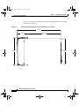
Figure 2-3 shows the outer dimensions of the Cisco XR 12404 Router chassis with
the front door installed.
Figure 2-3
Cisco XR 12404 Router Chassis Outer Dimensions—Top View
31.026
7.761
17.38 in.
66280
18.95 in.
23.265
Cisco XR 12404 Router Installation Guide
2-10
OL-13830-02
todd.book Page 11 Tuesday, July 24, 2007 3:54 PM
Chapter 2
Preparing for Installation
Installation Site Requirements
Environmental Guidelines
This section offers guidelines for operating your Cisco XR 12404 Router in
various environments; airflow, temperature and humidity, power source, AC and
DC powered routers, grounding connections and site wiring. To assure normal
operation and avoid maintenance difficulty, plan and prepare your site before you
install the router.
Airflow
The Cisco XR 12404 Router air circulation system consists of 1 fan tray assembly
mounted at the side of the chassis. The fan tray assembly maintains acceptable
operating temperatures for the internal components by drawing cooling air in
through a replaceable air filter, located on the right side of the chassis.
Air circulates through the card cage, and exhausts at the side of the chassis
(Figure 2-4).
•
Allow sufficient air flow by maintaining 6 inches (15.24 cm) of clearance at
both the inlet and exhaust openings on the chassis.
•
The site should be as dust-free as possible. Dusty environments can clog the
air filter, reducing the cooling airflow through the system. This can cause an
over temperature condition in the router.
Under extreme environment conditions, the environmental monitoring system
will shut down the power to protect the system components.
Cisco XR 12404 Router Installation Guide
OL-13830-02
2-11
todd.book Page 12 Tuesday, July 24, 2007 3:54 PM
Chapter 2
Preparing for Installation
Installation Site Requirements
Figure 2-4
Cisco XR 12404 Router Air Circulation System
2
3
3
1
4
6
5
66281
Top view
5
Temperature and Humidity
The operating environmental site requirements are listed in Appendix A. The
temperature and humidity ranges listed are those within which the router will
continue to operate. You can maintain normal operation by anticipating and
correcting environmental irregularities before they approach critical values.
The environmental monitoring functionality built into the router protects the
system and components from potential damage from overvoltage and
overtemperature conditions.
Cisco XR 12404 Router Installation Guide
2-12
OL-13830-02
todd.book Page 13 Tuesday, July 24, 2007 3:54 PM
Chapter 2
Preparing for Installation
Installation Site Requirements
Power Connection Guidelines
The Cisco XR 12404 Router requires an AC PEM or a combination DC PDU and
DC PEM. Site requirements differ depending on the type of power source voltage.
We recommend you follow these precautions and recommendations when
planning power source connections to your router.
•
Check the power at your site before installation and periodically after
installation to ensure that you are receiving clean power from the power
source.
•
If necessary, install a power conditioner.
•
Install proper grounding, or use the proper grounding receptacle located on
the side of the chassis, to avoid damage from lightning and power surges.
AC-Powered Routers
A Cisco XR 12404 Router configured with two AC PEMs, are shipped with a
three-wire electrical grounding-type plug that will only fit into a grounding-type
power outlet. This is a safety feature. The equipment grounding should be in
accordance with local and national electrical codes.
At sites where the Cisco XR 12404 Router operates with AC PEMs, observe the
following guidelines (Figure 2-3):
Caution
•
A power factor corrector (PFC) allows the PEM to accept AC power source
voltage from an AC power source operating between 100 to 120 VAC,
15–Amp service in North America; and a range of 185 to 264 VAC, 10–Amp
service, in an international environment.
•
All AC PEM power cords measure 14 feet (4.3 meters).
•
Provide a dedicated power source for each PEM installed in the router.
•
Install an uninterruptable power source where possible.
Use the North American plug L6-20 20A only on 240 volt systems.
Cisco XR 12404 Router Installation Guide
OL-13830-02
2-13
todd.book Page 14 Tuesday, July 24, 2007 3:54 PM
Chapter 2
Preparing for Installation
Installation Site Requirements
Cisco XR 12404 Router AC Power Plugs
North American plug
L6-20 20A
(for 240V units)
Australian plug
AS 3112 10A
European plug
CEE 7/7 16A
North American plug
5-15 15A
Italian plug
CEI 23-16/VII 10A
United Kingdom plug
BS 1363 13A
66969
Figure 2-5
Power Connection Guidelines for DC-Powered Routers
When the Cisco XR 12404 Router operates with a DC PDU, observe these
guidelines:
•
A Cisco XR 12404 Router configured with a DC PDU and DC-input PEMs has
a maximum power rating of 35A per power module and requires a dedicated DC
power source to support this maximum current. The facility DC source circuit
breaker protection needs to comply with safety local codes and regulations.
This circuit breaker protects against short-circuit and overcurrent faults in
accordance with United States National Electrical Code NFPA 70 (United
States), Canadian Electrical Code, part I, CSA C22.1 (Canada), and IEC 364
(other countries).
•
DC power cable leads should be #6 American Wiring Gauge (AWG)
high-strand-count wire.
•
Provide a dedicated power source for each power entry module installed in
the router.
Cisco XR 12404 Router Installation Guide
2-14
OL-13830-02
todd.book Page 15 Tuesday, July 24, 2007 3:54 PM
Chapter 2
Preparing for Installation
Installation Site Requirements
•
Install an uninterruptable power source where possible.
Grounding Connections
Before you connect power or turn on your Cisco XR 12404 Router, you must
provide an adequate system ground for the router. The equipment grounding
should be in accordance with local and national electrical codes.
For installations other than in a network equipment building system (NEBS)
environment, you may chose to rely on the safety earth ground connection
supplied via the International Electrotechnical Commission (IEC) 320 inlets for
AC-powered units and the main terminal block ground connection for
DC-powered units.
Site Wiring
This section offers site wiring guidelines for setting up the plant wiring and
cabling at your site. When planning the location of the new system, consider the
following:
•
Electromagnetic interference (EMI)
•
Distance limitations for signaling and unshielded conductors
Electromagnetic Interference
Electromagnetic interference can occur between the signal on the wires and
external or ambient EMI fields when the wires are run for any significant distance.
This fact has two implications for the construction of plant wiring.
•
Warning
Bad wiring practice can result in radio interference emanating from the plant
wiring.
Strong EMI, especially when it is caused by lightning or radio transmitters, can
destroy the signal drivers and receivers in the Cisco XR 12404 Router, and can
create an electrical hazard by conducting power surges through lines and may
cause damage to the equipment.
Cisco XR 12404 Router Installation Guide
OL-13830-02
2-15
todd.book Page 16 Tuesday, July 24, 2007 3:54 PM
Chapter 2
Preparing for Installation
Unpacking and Repacking the Cisco XR 12404 Router
Note
To predict and remedy strong EMI, you may need to consult experts in
radio frequency interference (RFI).
If you use twisted-pair cable in your plant wiring with a good distribution of
grounding conductors, the plant wiring is unlikely to emit radio interference. If
you exceed the recommended distances, use a high-quality twisted-pair cable with
one ground conductor for each data signal when applicable.
Distance Limitations
If wires exceed recommended distances, or if wires pass between buildings, give
special consideration to the effect of a lightning strike in your vicinity. The
electromagnetic pulse (EMP) caused by lightning or other high-energy
phenomena can easily couple enough energy into unshielded conductors to
destroy electronic devices. If you have had problems of this sort in the past, you
may want to consult experts in electrical surge suppression and shielding.
Most data centers cannot resolve the infrequent but potentially catastrophic
problems just described without pulse meters and other special equipment. These
problems can cost a great deal of time to identify and resolve, so take precautions
by providing a properly grounded and shielded environment, with special
attention to issues of electrical surge suppression.
Unpacking and Repacking the Cisco XR 12404 Router
The shipping package for Cisco XR 12000 Series Routers is engineered to reduce
the potential of product damage associated with routine material handling
experienced during shipment. To minimize potential damage to the product,
transport these products in their Cisco-specified packaging. Failure to do so may
result in damage to the router or degradation of its performance. Also, do not
remove the Internet router from its shipping container until you are ready to install
it. The router should always be transported or stored in an upright position. Keep
the router in the shipping container until you have determined where you will
install it.
Cisco XR 12404 Router Installation Guide
2-16
OL-13830-02
todd.book Page 17 Tuesday, July 24, 2007 3:54 PM
Chapter 2
Preparing for Installation
Transporting a Cisco XR 12000 Series Router
If you do not receive everything you ordered, contact a customer service
representative for assistance. See the section titled, “Obtaining Documentation,
Obtaining Support, and Security Guidelines” section on page -xii.
Transporting a Cisco XR 12000 Series Router
The shipping package for Cisco XR 12000 Series Routers is engineered to reduce
the potential of product damage associated with routine material handling
experienced during shipment. To minimize potential damage to the product,
transport these products in their Cisco-specified packaging. Failure to do so may
result in damage to the router or degradation of its performance. Also, do not
remove the Internet router from its shipping container until you are ready to install
it. The router should always be transported or stored in an upright position. Keep
the router in the shipping container until you have determined a location for
installation.
Site Preparation Checklist
Your Cisco XR 12404 Router is shipped with a site log(Table 2-1). Keep your site
log in a location near the router where anyone who performs tasks can have access
to it. Site log entries might include the following.
•
Installation Progress—Make entries in the site log to record installation
progress. You can note any difficulties encountered and remedies during the
installation process.
•
Upgrades, Removals, and Replacement Procedures—Use the site log as a
record of system maintenance and expansion history.
– FRU installed, removed, or replaced
– Cisco XR 12404 Router configuration changes
– Software upgrades
– Corrective or preventive maintenance procedures performed
– Intermittent problems
– Your comments
Cisco XR 12404 Router Installation Guide
OL-13830-02
2-17
todd.book Page 18 Tuesday, July 24, 2007 3:54 PM
Chapter 2
Preparing for Installation
Site Preparation Checklist
Table 2-1 shows a sample site log. You can make copies of the sample or design
your own site log.
Table 2-1
Date
Sample Site Log
Description of Action Performed or Symptom Observed
Initials
Cisco XR 12404 Router Installation Guide
2-18
OL-13830-02
todd.book Page 19 Tuesday, July 24, 2007 3:54 PM
Chapter 2
Preparing for Installation
Site Preparation Checklist
Cisco XR 12404 Router Installation Guide
OL-13830-02
2-19
todd.book Page 1 Tuesday, July 24, 2007 3:54 PM
CH A P T E R
3
Installing the Router
This chapter describes how to install a Cisco XR 12404 Router. It includes the
following sections:
•
Installing a Cisco XR 12404 Router, page 3-2
•
Connecting RP and Line Card Cables, page 3-12
•
Connecting to the Console Port and Auxiliary Ports, page 3-14
•
Connecting to an AC Power Source, page 3-23
•
Connecting to a DC Power Source, page 3-25
•
Powering on the Router for the First Time, page 3-28
•
External Network Interface, page 3-32
•
Manually Booting the System, page 3-32
Cisco XR 12404 Router Installation Guide
OL-13830-02
3-1
todd.book Page 2 Tuesday, July 24, 2007 3:54 PM
Chapter 3
Installing the Router
Installing a Cisco XR 12404 Router
Required Tools
You need the following items to install the Cisco XR 12404 Router:
•
Number 2 Phillips screwdriver
•
Small flat-bladed screwdriver
•
Tape measure (optional)
•
Level (optional)
Installing a Cisco XR 12404 Router
This section provides the procedures for installing the Cisco XR 12404 Router in
a rack or on a flat surface. It contains the following procedures:
•
Installing the Rack-Mounting Brackets—Optional
•
Installing the Chassis in a Rack
•
Installing the Chassis on a Tabletop or Flat Surface
•
Installing the Chassis on a Tabletop or Flat Surface
Your installation site should already be prepared before you begin installing the
router. For complete information about site preparation see Chapter 2, “Preparing
for Installation.”
Make sure that you have considered the following before you install the router:
•
Mounted at the left side of the chassis is the fan tray, the exhaust vents should
not be blocked.
•
Facing the rear of the router, mounted on the left side is the air filter; air flow
to the air filter should not be blocked.
•
24 inches (61 centimeters) of clearance in front of the chassis may be needed
for working with line cards, attaching Network Interface Cables (NICs), the
CSF or the RP.
•
Location is temperature-controlled, air-conditioned and dust-free.
•
Power cables and power supplies have been checked for compatibility with
your power service.
Cisco XR 12404 Router Installation Guide
OL-13830-02
3-2
todd.book Page 3 Tuesday, July 24, 2007 3:54 PM
Chapter 3
Installing the Router
Installing a Cisco XR 12404 Router
•
Labels on the equipment have been checked to ensure that the power service
at your site is suitable for the Cisco XR 12404 Router.
•
AC and DC power source voltage receptacles are easy to reach.
Installing the Rack-Mounting Brackets—Optional
The rack-mounting brackets temporarily bear the weight of the router while it is
being positioned in the rack.
While the use of the rack-mounting is optional, installing them makes it much
easier to mount the router in a rack, and also ensures that the router is level. The
rack-mounting brackets can be left in place following the router installation.
Warning
Two or more people should install the router to minimize the risk of personal
injury and damage to the equipment.
Refer to Figure 3-1 and use the following procedure to install the rack-mounting
brackets.
Step 1
Measure and mark the hole at the same height on both the left and right rack rails.
Step 2
Hold the right bracket against the right mounting rail and align the bottom screw
hole in the bracket with the marked screw hole.
Step 3
While supporting the bracket against the mounting rail with one hand, use the
other hand to insert a screw through a hole in the rack-mounting bracket.
Step 4
Finger-tighten the screw.
Step 5
Insert a second screw in the top hole in the bracket and finger tighten the screw.
Step 6
Mount the left rack-mounting bracket the same as you mounted the right bracket.
Step 7
Measure the two brackets to ensure they are positioned at the same height.
Step 8
Use a level to ensure the tops of the two brackets are level, or use a measuring tape
to ensure that each bracket is the same distance from the top of both rack rails.
Step 9
Use a screwdriver to tighten all the screws (Figure 3-1).
Cisco XR 12404 Router Installation Guide
3-3
OL-13830-02
todd.book Page 4 Tuesday, July 24, 2007 3:54 PM
Chapter 3
Installing the Router
Installing a Cisco XR 12404 Router
Figure 3-1
Rack-Mounting Brackets
1 1/4"
2 1/2"
1/16" sheet metal
3 3/8"
3/4"
Right mounting rail
57802
Left mounting rail
Cisco XR 12404 Router Installation Guide
OL-13830-02
3-4
todd.book Page 5 Tuesday, July 24, 2007 3:54 PM
Chapter 3
Installing the Router
Installing a Cisco XR 12404 Router
Installing the Center-Mounting Brackets—Optional
If you plan to install the Cisco XR 12404 Router in the center-mounting position,
you must first install the center-mounting brackets on the equipment rack rails,
then secure the chassis to the center-mounting brackets. If you do not plan to use
the optional center-mounting brackets, proceed directly to the “Installing the
Chassis in a Rack” section on page 3-7.
The optional center-mounting bracket installation kit ships in an accessories box
included in the Cisco XR 12404 Router shipping container.
Refer to Figure 3-2 and use the following procedure to install the optional
center-mounting brackets.
Step 1
Measure and mark the hole at the same height on both the left and right posts.
Step 2
Hold the right bracket against the right rack rail and align the bottom screw hole
in the bracket with the marked screw hole.
Step 3
While supporting the bracket against the rack rail with one hand, use the other
hand to insert a screw through a hole in the center-mounting bracket that aligns
with a hole on the rack rail.
Step 4
Use your fingers to tighten the screw.
Step 5
Insert a second screw in the top hole in the bracket and finger tighten the screw.
Step 6
Use a screwdriver to tighten all the screws.
Step 7
Mount the left center-mounting bracket so that it is at the same height as the right
bracket.
Step 8
Use a level to ensure the two brackets are level; or use a measuring tape to ensure
the both center-mounting brackets are the same distance from the top of both rack
mounting rails.
Step 9
Use a screwdriver to tighten all the screws.
Cisco XR 12404 Router Installation Guide
3-5
OL-13830-02
todd.book Page 6 Tuesday, July 24, 2007 3:54 PM
Chapter 3
Installing the Router
Installing a Cisco XR 12404 Router
Figure 3-2
CONNECTO
R
CLASS 1 LASER
LASERPRODUKT PRODUCT
PRODUIT LASER DER KLASSE 1
DE CLASSE
1
PRODUCTO LASER
DE CLASSE 1
TX
0
1
RX
2
3
EJ
EC
ACTIVE
CARRIER
T
SL
SL
-1
OT
-0
OT
RE
SE
RX PKT
T
X
AU
40C48/PO
LL
CO RX
OLE
NS
CO
RJ
LINK
-45
66286
CLEAN
WITH ALCOHOL
WIPES
BEFORE
CONNECTING
Center-Mounting Brackets
S-SR-SC
TX
MII
CR
IT
IC MA M
AL JO IN
R O
GIGABIT
ROUTE
R
PROCES
SOR
MBUS
ALARM FABRIC
FAIL
ENABLE
CONSOL
IDATED
SWI
TCH FAB
RIC
1
Cisco XR 12404 Router Installation Guide
OL-13830-02
3-6
todd.book Page 7 Tuesday, July 24, 2007 3:54 PM
Chapter 3
Installing the Router
Installing a Cisco XR 12404 Router
Installing the Chassis in a Rack
Use the following procedure to install the Cisco XR 12404 Router in a rack.
Warning
Two or more people should install the router to minimize the risk of personal
injury and damage to the equipment.
Step 1
Move the router as close to the installation location as possible without interfering
with the installation process.
Step 2
With one person lifting from the front and one from the rear of the chassis, lift the
chassis off the pallet and position the chassis in the rack.
Note
Step 3
A third person might be needed to assist in lifting and positioning the
chassis in the rack, or to install the screws once the chassis is in position.
Install the screws to secure the chassis to the rack
a.
Look at the bottom mounting holes on the chassis. Align one of the holes with
a mounting hole in the rack.
b.
Install one of the mounting screws provided.
c.
On the other side of the chassis adjust the position of the chassis so that the
same mounting hole in the bottom group of mounting holes is aligned with a
hole in the rack.
d.
Install one of the mounting screws provided.
Step 4
Repeat Step 3a through Step 3d for additional mounting holes.
Step 5
Use a screwdriver to tighten all the screws.
Cisco XR 12404 Router Installation Guide
3-7
OL-13830-02
todd.book Page 8 Tuesday, July 24, 2007 3:54 PM
Chapter 3
Installing the Router
Supplemental Bonding and Grounding Connections
Installing the Chassis on a Tabletop or Flat Surface
Use the following procedure to install the Cisco XR 12404 Router on a tabletop
or other stable flat surface.
Step 1
Move the router as close to the installation location as possible.
Step 2
With one person positioned at the front and rear of the chassis, lift the chassis off
of the pallet and position the chassis on the flat surface.
Step 3
Secure the chassis to the flat surface to ensure it does not fall off.
You can use the same mounting hardware that secured your router to the shipping
pallet to secure the chassis to the flat surface.
Supplemental Bonding and Grounding Connections
Before you connect power or turn on your Cisco XR 12404 Router, you must
provide an adequate system ground for the router. The equipment grounding
should be in accordance with local and national electrical codes.
If you are not installing the Cisco XR 12404 Router in a NEBS environment, you
can choose to bypass these guidelines and rely on the safety earth ground
connection supplied via the 5-15 15A North American plug to the AC-powered
PEMs, and the main terminal block ground connection for DC-powered PEMs.
•
On Cisco XR 12404 Routers configured for AC-input operation, the AC PDU
is equipped with a three-wire electrical grounding-type connector that accept
three-wire, grounding-type AC power cords such as the power cords shipped
with the router. This is a safety feature.
Cisco XR 12404 Router Installation Guide
OL-13830-02
3-8
todd.book Page 9 Tuesday, July 24, 2007 3:54 PM
Chapter 3
Installing the Router
Supplemental Bonding and Grounding Connections
•
On Cisco XR 12404 Routers configured for DC-input operation, the DC PDU
is equipped with a DC power connector block with wire-connection terminals
for connecting the negative lead (top terminal), the positive lead (middle
terminal), and the ground lead (bottom terminal). This is a safety feature.
Cisco XR 12404 Router grounding architecture conforms to the DC-I
(DC-isolated) method of grounding as described in Telcordia
GR-1089-CORE. A DC-I architecture means that there is no connection
between the DC return terminal and the frame ground. DC return and
frame ground are isolated from one another at the router.
Note
If the router is installed in a NEBS environment, we strongly recommend that you
connect the central office ground system or interior equipment grounding system
to the supplemental bonding and grounding point on the router chassis. This
grounding point consists of threaded inserts is located on the side of the chassis
near the back of the chassis (see Figure 3-3). It is also referred to as the NEBS
bonding and grounding receptacle, and is intended to satisfy the Telcordia NEBS
requirements for supplemental bonding and grounding connections.
Figure 3-3
CLEAN
CONNECTOR
WITH ALCOHOL
WIPES
BEFORE
CONNECTING
Supplemental Bonding and Grounding Port for NEBS
Compliance
CLASS 1 LASER
LASERPRODUKT PRODUCT
PRODUIT LASER DER KLASSE 1
DE CLASSE 1
PRODUCTO LASER
DE CLASSE 1
TX
0
1
RX
2
3
EJ
EC
ACTIVE
CARRIER
T
SL
SL
-1
OT
-0
OT
RE
SE
RX PKT
T
X
AU
E
OL
NS
CO
CO
RX
RJ
LIN
K
40C48/POS
-SR-SC
LL
-45
TX
MI
CR
IT MA
IC
AL JO MINO
R
R
I
GIGABIT
ROUTE
PROCESSO
R
MBUS
ALARM FABRIC
FAIL
ENABLE
DATED
SWITCH
FABRIC
66245
CONSOLI
Cisco XR 12404 Router Installation Guide
3-9
OL-13830-02
todd.book Page 10 Tuesday, July 24, 2007 3:54 PM
Chapter 3
Installing the Router
Supplemental Bonding and Grounding Connections
Use a cable lug with two holes at 0.63" (16 mm) centers to connect to the chassis
with two 6.3 mm (M6) screws as shown in Figure 3-4. The lug can be ordered
from Cisco (Part Number 32-0607-01).
Figure 3-4
Cable Lug
All measurements in inches
2.24
End View
0.48
Ø 0.267
2 holes
0.25
0.63
0.37
0.08
25527
Crimp area
The dual-hole lug is crimped onto a grounding wire of a wire size and length
determined by your router location and facility environment. The crimping tool
shown in Figure 3-5 is a standard crimping tool obtainable from any normal
hardware source.
Cisco XR 12404 Router Installation Guide
OL-13830-02
3-10
todd.book Page 11 Tuesday, July 24, 2007 3:54 PM
Chapter 3
Installing the Router
Supplemental Bonding and Grounding Connections
Figure 3-5
Crimping the Lug
57808
1
2
1
Place ground wire in the lug
2
Crimp the lug
Cisco XR 12404 Router Installation Guide
3-11
OL-13830-02
todd.book Page 12 Tuesday, July 24, 2007 3:54 PM
Chapter 3
Installing the Router
Connecting RP and Line Card Cables
Connecting RP and Line Card Cables
Use the following procedure to connect RP and line card cables to the router.
Figure 3-6
Step 1
Proceeding from left to right identify the network interface cable that connects to
each card port.
Step 2
Connect the network interface cables:
a.
Carefully route the identified cable through the cable-management tray and
over to the card interface port; connect one cable at a time (Figure 3-6).
b.
Proceeding from left to right carefully wrap the cables using the velcro straps.
RP and Line Card Cable-Management Brackets
Line card
cable management
bracket
E R L
TIV RIE EL
AC CAR RX C
0
E R L
TIV RIE EL
AC CAR RX C
0
E R L
TIV RIE EL
AC CAR RX C
0
E R L
TIV RIE EL
AC CAR RX C
OC-12/
STM-4
POS
Network
interface
cables
0
E R L
TIV RIE EL
AC CAR RX C
0
E R L
TIV RIE EL
AC CAR RX C
0
Velcro
strap
E R L
TIV RIE EL
AC CAR RX C
57803
E R L
TIV RIE EL
AC CAR RX C
OC-12/
STM-4
POS
Cisco XR 12404 Router Installation Guide
OL-13830-02
3-12
todd.book Page 13 Tuesday, July 24, 2007 3:54 PM
Chapter 3
Installing the Router
Connecting RP and Line Card Cables
Caution
Carefully adjust the interface cable in the RP or line card cable-management
bracket to prevent any kinks or sharp bends in the interface cable. Kinks and sharp
bends can destroy or degrade the ability of the optical fiber to propagate the
signal-encoded beam of light accurately from one end of the cable to the other.
Also, allow adequate strain relief in the interface cable.
Step 3
Route the cable to the chassis cable-management bracket mounted to the left side
of the chassis (Figure 3-7).
Use the screws packaged with the chassis cable management bracket kit.
Figure 3-7
Chassis Cable-Management Bracket
CLEAN
CONNEC
TOR
WITH ALCOHOL
WIPES
BEFORE
CONNECTI
NG
CLASS 1 LASER
LASERPRODUK PRODUCT
PRODUIT LASERT DER KLASSE 1
DE CLASSE
1
PRODUCTO LASER
DE CLASSE 1
TX
0
1
RX
2
3
EJE
CT
ACTIVE
CARRIER
T-1
SLO 0
TSLO
S
RE
RX PKT
ET
X
AU
OLE
NS
CO
C
OLL
RX
RJ-
K
LIN
40C48/P
OS-SR-SC
45
TX
MII
GIGABI
T ROUTE
CR
IT M
IC A M
AL JO IN
R OR
PROCES
SOR
66276
•
MBUS
ALARM FABRIC
FAIL
ENABLE
CONSO
LIDATE
D SW
ITCH FAB
RIC
Cisco XR 12404 Router Installation Guide
3-13
OL-13830-02
todd.book Page 14 Tuesday, July 24, 2007 3:54 PM
Chapter 3
Installing the Router
Connecting to the Console Port and Auxiliary Ports
Connecting to the Console Port and Auxiliary Ports
This section provides the information to connect a console to the router. Both Data
Set Ready (DSR) and Data Carrier Detect (DCD) signals are active when the
system is running. The console port does not support modem control or hardware
flow control. The console port requires a straight-through EIA/TIA-232 cable.
The system console port on the PRP is a DCE RJ-45 receptacle for connecting a
data terminal, which you must configure. The console port is labeled Console, as
shown in Figure 3-8.
Note
To comply with Telcordia GR-1089 NEBS standard for electromagnetic
compatibility and safety, connect all console, auxiliary, Ethernet, and BITS
interfaces only to intrabuilding or non-exposed wiring or cabling. The
intrabuilding cable must be shielded and the shield must be grounded at both ends.
Check your terminal’s documentation to determine the baud rate of the terminal
you plan to use. If your documentation does not specify settings use the following
terminal settings:
1.
Baud to 9600
2.
Data bits to 8
3.
Parity to no parity
4.
Stop bits to 2
The console port requires a straight-through RJ-45 cable.
Cisco XR 12404 Router Installation Guide
OL-13830-02
3-14
todd.book Page 15 Tuesday, July 24, 2007 3:54 PM
Chapter 3
Installing the Router
Connecting to the Console Port and Auxiliary Ports
Figure 3-8
PRP Console and Auxiliary Port Connections
EN
K
LIN
ETH 0
PRIMARY
-1
OT
SL 0
OT
SL
1
EN
K
LIN
ETH 1
PRIMARY
RX
TX
3
RX
AUX
CONSOLE
5
70692
TX
4
2
Note
1
Modem
4
Auxiliary port
2
Console terminal
5
Console port
3
RJ-45 Ethernet cables
The console and auxiliary ports are both asynchronous serial ports; any devices
connected to these ports must be capable of asynchronous transmission.
(Asynchronous is the most common type of serial device; for example, most
modems are asynchronous devices.)
Cisco XR 12404 Router Installation Guide
3-15
OL-13830-02
todd.book Page 16 Tuesday, July 24, 2007 3:54 PM
Chapter 3
Installing the Router
Connecting to the Console Port and Auxiliary Ports
PRP Console Port Signals
The console port on the PRP is a DCE RJ-45 receptacle. Table 3-1 lists the signals
used on this port.
Table 3-1
PRP Console Port Signals
Console Port Pin
Signal
Input/Output
Description
11
—
—
—
2
DTR
Output
Data Terminal Ready
3
TxD
Output
Transmit Data
4
GND
—
Signal Ground
5
GND
—
Signal Ground
6
RxD
Input
Receive Data
DSR
Input
Data Set Ready
—
—
—
7
8
1
1. These pins are not connected.
Cisco XR 12404 Router Installation Guide
OL-13830-02
3-16
todd.book Page 17 Tuesday, July 24, 2007 3:54 PM
Chapter 3
Installing the Router
Installing a Flash Memory Card
PRP Auxiliary Port Signals
The auxiliary port on the PRP is a DTE, RJ-45 plug for connecting a modem or
other DCE device (such as a CSU/DSU or another router) to the router. The port
is labeled Aux, as shown in Figure 3-8. The asynchronous auxiliary port supports
hardware flow control and modem control. Table 3-2 lists the signals used on the
auxiliary port.
Table 3-2
PRP Auxiliary Port Signals
Auxiliary Port Pin
Signal
Input/Output Description
1
RTS
Output
Request To Send
2
DTR
Output
Data Terminal Ready
3
TxD
Output
Transmit Data
4
GND
—
Signal Ground
5
GND
—
Signal Ground
6
RxD
Input
Receive Data
7
DSR
Input
Data Set Ready
8
CTS
Input
Clear To Send
Installing a Flash Memory Card
By default, a Flash memory card containing a valid Cisco IOS XR software image
is inserted in bottom slot, PCMCIA slot 0 before the router is shipped.
Note
PCMCIA slot 0 is the bottom slot and slot 1 is the top slot. Both Flash memory
card slots on each RP can be used at the same time.
Cisco XR 12404 Router Installation Guide
3-17
OL-13830-02
todd.book Page 18 Tuesday, July 24, 2007 3:54 PM
Chapter 3
Installing the Router
Connecting the PRP to an Ethernet Network
The software configuration register is set to 0x0102, which causes the router to
boot automatically from the Cisco IOS XR software image stored on the Flash
memory card.
•
The Flash memory card that shipped with your system is installed in the
bottom slot, PCMCIA slot 0 of the RP (Figure 3-9).
Figure 3-9
Flash Memory Card Slots
-1
OT
SL -0
OT
SL
T
SE
RE
X
AU
57080
T
EC
EJ
Ensure that a console terminal is connected to the RP console port and turned on,
or that you have a remote login to the router from another device through a telnet
session.
Connecting the PRP to an Ethernet Network
The PRP includes two 10/100 Mbps Ethernet ports, each using an 8-pin RJ-45
receptacle for either IEEE 802.3 10BASE-T (10 Mbps) or IEEE 802.3u
100BASE-TX (100 Mbps) connections. The transmission speed of the Ethernet
ports is auto-sensing by default and is user configurable.
To connect cables to the PRP Ethernet interfaces (ports labeled ETH0 and ETH1),
attach the Category 5 UTP cable directly to a RJ-45 receptacle on the PRP.
Note
The Ethernet interfaces on the PRP are end-station devices, not repeaters;
therefore, you must connect an Ethernet interface to a repeater or hub.
Cisco XR 12404 Router Installation Guide
OL-13830-02
3-18
todd.book Page 19 Tuesday, July 24, 2007 3:54 PM
Chapter 3
Installing the Router
Connecting the PRP to an Ethernet Network
RJ-45 cables are not available from Cisco Systems, but are available from outside
commercial cable vendors.
Note
Only connect cables that comply with EIA/TIA-568 standards. See Table 3-4 and
Table 3-5 for cable recommendations and specifications.
Note
To comply with Telcordia GR-1089 NEBS standard for electromagnetic
compatibility and safety, connect all console, auxiliary, and Ethernet interfaces
only to intrabuilding or non-exposed wiring or cabling. The intrabuilding cable
must be shielded and the shield must be grounded at both ends.
Caution
The Ethernet ports are primarily used as a Telnet port into the Cisco XR 12000
Series Router, and for booting or accessing Cisco IOS XR software images over
a network to which an Ethernet port is directly connected. Cisco Express
Forwarding (CEF) functions are switched off by default for security reasons.
Cisco strongly cautions you to consider the security implications of switching on
CEF routing functions on these ports.
Figure 3-10 is an example of the functionality of an Ethernet port. In this example,
you cannot access Network 2.0.0.0 through the Ethernet port (ETH0) on the PRP
in router A; you can only access the hosts and router C, which are in Network
1.0.0.0 (see dotted arrows in Figure 3-10).
To access Network 2.0.0.0 from router A, you must use an interface port on one
of your line cards (in this example, a Packet-over-SONET (POS) line card in
router A) to go through router B, through router C, and into Network 2.0.0.0 (see
solid arrows in Figure 3-10).
Cisco XR 12404 Router Installation Guide
3-19
OL-13830-02
todd.book Page 20 Tuesday, July 24, 2007 3:54 PM
Chapter 3
Installing the Router
Connecting the PRP to an Ethernet Network
Figure 3-10
Using the Ethernet Port on the PRP
Network 1.0.0.0
Router A
(Cisco 12000 series)
Host A
EO
POS
Host B
Network 2.0.0.0
EO
Router B
(Cisco 7500 series)
S6755
Host A
Router C
(Cisco 7500 series)
PRP Ethernet Connections
Figure 3-11 shows a PRP RJ-45 receptacle and cable connectors. The RJ-45
connection does not require an external transceiver. The RJ-45 connection
requires Category 5 unshielded twisted-pair (UTP) cables, which are not available
from Cisco Systems, but are available from commercial cable vendors. Table 3-3
lists the port pinouts for the RJ-45 receptacle.
87654321
RJ-45 connector
RJ-45 Receptacle and Plug (Horizontal Orientation)
210222
Figure 3-11
Cisco XR 12404 Router Installation Guide
OL-13830-02
3-20
todd.book Page 21 Tuesday, July 24, 2007 3:54 PM
Chapter 3
Installing the Router
Connecting the PRP to an Ethernet Network
Warning
The ports labeled Ethernet, 10BASE-T, Token Ring, Console, and AUX are safety
extra-low voltage (SELV) circuits. SELV circuits should only be connected to
other SELV circuits. Because the BRI circuits are treated like
telephone-network voltage, avoid connecting the SELV circuit to the telephone
network voltage (TNV) circuits.
Table 3-3
PRP RJ-45 Ethernet Receptacle Pinout
Ethernet Port Pin
Signal
Description
1
TxD+
Transmit data +
2
TxD–
Transmit data –
3
RxD+
Receive data +
4
Termination Network
No connection
5
Termination Network
No connection
6
RxD–
Receive data –
7
Termination Network
No connection
8
Termination Network
No connection
Depending on your RJ-45 cabling requirements, use the cable pinouts shown in
Figure 3-12 or Figure 3-13.
Straight-Through Cable Pinout—Connecting MDI Ethernet Port
to MDI-X Wiring
MDI wiring
MDI-X wiring
1 TxD+
1 RxD+
2 TxD–
2 RxD–
3 RxD+
3 TxD+
6 RxD–
6 TxD–
H11007
Figure 3-12
Cisco XR 12404 Router Installation Guide
3-21
OL-13830-02
todd.book Page 22 Tuesday, July 24, 2007 3:54 PM
Chapter 3
Installing the Router
Connecting the PRP to an Ethernet Network
Crossover Cable Pinout (for Connecting Two PRPs)
PRP
PRP
1 TxD+
1 TxD+
2 TxD–
2 TxD–
3 RxD+
3 RxD+
6 RxD–
6 RxD–
75431
Figure 3-13
Table 3-4 lists the cabling specifications for 100-Mbps transmission over
unshielded twisted-pair (UTP) cables.
Note
The transmission speed of the Ethernet ports is auto-sensing by default and is user
configurable.
Table 3-4
Specifications and Connection Limits for 100-Mbps
Transmission
Parameter
RJ-45
Cable specification
Category 5 1 UTP, 22 to 24 AWG2
Cable length (max)
—
Segment length (max)
328 feet (100 m) for 100BASE-TX
Network length (max)
656 feet (200 m)3 (with 1 repeater)
1. EIA/TIA-568 or EIA-TIA-568 TSB-36 compliant. Not supplied by Cisco.
2. AWG = American Wire Gauge. This gauge is specified by the EIA/TIA-568 standard.
3. This length is specifically between any two stations on a repeated segment.
Cisco XR 12404 Router Installation Guide
OL-13830-02
3-22
todd.book Page 23 Tuesday, July 24, 2007 3:54 PM
Chapter 3
Installing the Router
Connecting to an AC Power Source
Table 3-5 lists IEEE 802.3u physical characteristics for 100BASE-TX.
Table 3-5
IEEE 802.3u Physical Characteristics
Parameter
100BASE-TX
Data rate (Mbps)
100
Signaling method
Baseband
Maximum segment length
100 m between DTE1 and repeaters
Media
Category 5 UTP (for RJ-45)
Topology
Star/Hub
1. DTE = data terminal equipment.
Connecting to an AC Power Source
This section provides the procedure for connecting your router to an AC power
source. A power factor corrector (PFC) allows the AC-input power supply to
accept AC power source voltage from an AC power source operating between
100-120 VAC, 15-Amp service in North America; and a range of 185-264 VAC,
10-Amp service in an international environment.
Caution
The AC PEM weighs 14.0 pounds (6.35 kg.). Use two hands when handling a
PEM.
Step 1
Attach an ESD-preventive strap to yourself and to either the chassis, or to a bare
metal surface.
Step 2
Using two hands to support and guide the PEM, slide it into the PEM bay. Push
the PEM all the way into the bay until the PEM connector engages the backplane
connector.
Cisco XR 12404 Router Installation Guide
3-23
OL-13830-02
todd.book Page 24 Tuesday, July 24, 2007 3:54 PM
Chapter 3
Installing the Router
Connecting to an AC Power Source
Step 3
Tighten the captive screws on the PEM faceplate (Figure 3-14).
Figure 3-14
1
AC PEM
2
3
INPUT
OK
INPUT
100-240
V
12A
OUTPUT
OUTPUT
OK
FAIL
66289
50/80HZ
6
Step 4
4
1
AC PEM handle
4
Power cord receptacle
2
On/Off switch
5
LEDs
3
Bail latch
6
Captive screws
•
All electrical connections between the power supply and the backplane are
made automatically when the power supply is fully inserted in the power
supply bay.
Locate the AC power cord and remove it from its shipping packaging. Verify that
the AC power cord shipped with the power supply is the correct type for your site.
Note
Step 5
5
If you have an incorrect type of power cord, contact your service
representative for a replacement.
Plug the AC power cord into the AC PEM.
Cisco XR 12404 Router Installation Guide
OL-13830-02
3-24
todd.book Page 25 Tuesday, July 24, 2007 3:54 PM
Chapter 3
Installing the Router
Connecting to a DC Power Source
Step 6
Connect the other end of the AC power cord to the AC power source outlet.
Note
We recommend attaching each AC PEM to an independent power source
for full redundancy. We also recommend that you use an uninterruptable
power source (UPS) to protect against power failures at your site.
Note
When operating your router on an AC power source, both PEM bays must
have all AC PEMs installed to ensure compliance with regulatory EMI
standards.
Connecting to a DC Power Source
Each DC PDU should be connected to separate DC sources using six threaded
terminals. Two terminals for negative (source DC), two terminals for positive
(source DC return), and two terminals for ground. The DC power cable leads
should be 6 American Wiring Gauge (AWG) high strand count wire. The PEM
accepts DC power source voltage from a dedicated 35–Amp service DC power
source operating between -48 to -60 VDC.
Warning
Power to your router must be Off and all cables disconnected before you install
the DC power assembly. The DC PDU and DC PEM when connected, is not a
hot-swappable field replaceable unit.
Note
We recommend each DC PDU be connected to an independent power source for
full redundancy. We also recommend that you use an uninterruptable power
source (UPS) to protect against power failures at your site.
Caution
The DC PEM and DC PDU assembly weighs 14.0 pounds (6.35 kg.). Use two
hands when handling the power supply.
Cisco XR 12404 Router Installation Guide
3-25
OL-13830-02
todd.book Page 26 Tuesday, July 24, 2007 3:54 PM
Chapter 3
Installing the Router
Connecting to a DC Power Source
Use the following procedure to install the DC PEM and DC PDU in the router.
Figure 3-15
Step 1
Attach an ESD-preventive strap to yourself and to either the chassis, or to a bare
metal surface.
Step 2
Insert the DC power module into the power module bay at the rear of the chassis
(Figure 3-15).
DC Powered Cisco XR 12404 Router—Rear View
INPUT
– 48/60V
35A
INPUT
OK
OUTPU
T
OK
OUTPU
T
FAIL
INPUT
OK
OUTPU
T
OK
66288
INPUT
– 48/60V
35A
OUTPU
T
FAIL
Step 3
Press the module against the backplane until the connectors are seated against
the backplane receptacles.
Step 4
Tighten all of the captive screws on the faceplate.
All electrical connections between the power supply and the backplane happen
automatically when the power supply is fully inserted in the power supply bay.
Step 5
Tighten the captive screws on the DC PDU.
Cisco XR 12404 Router Installation Guide
OL-13830-02
3-26
todd.book Page 27 Tuesday, July 24, 2007 3:54 PM
Chapter 3
Installing the Router
Connecting to a DC Power Source
Step 6
Secure each lead to the proper terminal port by tightening the terminal port
connector screws with a 3/16-inch flat-blade screw driver (Figure 3-16).
Figure 3-16
DC PDU Power Block
+
4
1
2
66949
GN
D 3
Step 7
1
Negative Terminal Port
3
Ground Terminal Port
2
Positive Terminal Port
4
Terminal Port Connector Screws
Verify that the DC power source circuit breaker servicing the DC PEM is
switched on.
Cisco XR 12404 Router Installation Guide
3-27
OL-13830-02
todd.book Page 28 Tuesday, July 24, 2007 3:54 PM
Chapter 3
Installing the Router
Powering on the Router for the First Time
Powering on the Router for the First Time
Use the following procedure to power on the router for the first time.
Step 1
Check the following list before you power on the router:
•
All cards are fully inserted in the card and CSF cage and all captive screws
are tight
Caution
Do not overtighten the captive screws on the cards you might strip the
threads on the screw or in the insert in the component faceplate.
•
Line card cable-management brackets are attached to their respective line
cards
•
Interface cables are routed neatly through the line card cable-management
bracket
•
Interface cables are completely seated in their line card connectors
•
Interface cables are routed neatly through the chassis cable-management
bracket
•
PEMs are fully inserted in to each AC PEM bay or DC PDU and DC PEM bay
•
PEM cables are securely connected to the PEM
•
Power cables are securely connected to the PDU, the power source and are
secured with appropriate strain relief.
•
Empty card slots or card bays are filled with card blanks to ensure proper air
flow through the chassis and electromagnetic compatibility (EMC)
Cisco XR 12404 Router Installation Guide
OL-13830-02
3-28
todd.book Page 29 Tuesday, July 24, 2007 3:54 PM
Chapter 3
Installing the Router
Powering on the Router for the First Time
Step 2
Power on the router by switching on all the circuit breakers and/or plug the power
cord into an active power source that controls power to the router’s AC PEM or
DC power distribution unit (PDU).
Step 3
You should observe the following LED confirmation:
•
AC PEMs—Verify the AC PEM LEDs are on and that the status is OK
(Figure 3-17).
Figure 3-17
AC PEM LEDs
INPUT
INPUT
100-240
V
12A
50/80HZ
OUTPUT
OUTPUT
OK
FAIL
66290
OK
INPUT OUTPUT OUTPUT
FAIL
OK
OK
1
2
3
1
Input OK
Green
AC is present and within specified limits
2
Output OK
Green
Power supply module is operating normally in
a powered up condition
3
Output Fail
Amber
Power module is operating in a fault condition
and shutdown has occurred
Cisco XR 12404 Router Installation Guide
3-29
OL-13830-02
todd.book Page 30 Tuesday, July 24, 2007 3:54 PM
Chapter 3
Installing the Router
Powering on the Router for the First Time
•
DC PEMs—Verify the DC PEM LEDs are on and that the status is OK
(Figure 3-18).
Figure 3-18
DC PEM LEDs
INP UT
– 48/ 60V
35A
OK
1
OUTPUT
OK
OUTPUT
FAIL
66399
INPUT
2
INPUT OUTPUT OUTPUT
OK
FAIL
OK
3
4
5
1
DC PDU
N/A
N/A
2
DC PEM
N/A
N/A
3
Input OK
Green
DC is present and within
specified limits
4
Output OK
Green
Power supply module is
operating normally in a powered
up condition
5
Output Fail
Amber
Power module is operating in a
fault condition and shutdown has
occurred
Cisco XR 12404 Router Installation Guide
OL-13830-02
3-30
todd.book Page 31 Tuesday, July 24, 2007 3:54 PM
Chapter 3
Installing the Router
Powering on the Router for the First Time
•
Visually check the CSF LEDs (Figure 3-19):
Figure 3-19
CSF LEDs
CR
ITIC MA MIN
AL JOR OR
MBUS
ALARM FABRIC
FAIL
CONSOLIDATED SWITCH FABRIC
CR
M
M
CA AJO INO
R
R
L
ITI
MBUS
ALARM FABRIC
FAIL
ENABLE
Table 3-6
CSF LEDs
Switch Fabric LEDs
Status
Condition
Critical
Off
Normally Off
Major
Off
Normally Off
Minor
Off
Normally Off
Table 3-7
CSF MBus Alarm LEDs
MBus Alarm LEDs
Status
Condition
Fail
Off
Normally Off
Enable
On
Normally On
Table 3-8
CSF MBus LEDs
MBus Fabric LEDs
Status
Condition
Fail
Off
Normally Off
Enable
On
Normally On
Cisco XR 12404 Router Installation Guide
3-31
OL-13830-02
66246
ENABLE
todd.book Page 32 Tuesday, July 24, 2007 3:54 PM
Chapter 3
Installing the Router
External Network Interface
Step 4
On the console terminal, verify that the console displays the system banner and
that the system and all interfaces initialize successfully.
If the router does not power on, or if any interfaces do not initialize properly, see
Chapter 4, “Troubleshooting the Installation,”. If you are still unable to resolve
the problem, contact your Cisco service representative for assistance.
External Network Interface
After configuration, the RP and line cards can communicate with external
networks.
You do not need to configure the network interfaces immediately, but you cannot
connect to a network until you configure the interfaces for operation in your
networking environment.
Note
The interface-specific LEDs on the line cards go on when the line card interfaces
are configured.
To verify correct operation of each line card interface, complete the first-time
setup procedures and configuration, then check the status of the interfaces against
the LED descriptions in the configuration notes for each line card.
If the system does not complete each of the boot process steps, go to “Chapter 4,
“Troubleshooting the Installation.”
Manually Booting the System
If your router does not find a valid system configuration image, or if you interrupt
the boot sequence, the system might enter read-only memory (ROM) monitor
mode and display the ROM monitor prompt (rommon>). From ROM monitor
mode, you have access to a number of commands to locate and boot a valid system
image.
Cisco XR 12404 Router Installation Guide
OL-13830-02
3-32
todd.book Page 33 Tuesday, July 24, 2007 3:54 PM
Chapter 3
Installing the Router
Manually Booting the System
Cisco XR 12404 Router Installation Guide
3-33
OL-13830-02
todd.book Page 1 Tuesday, July 24, 2007 3:54 PM
CH A P T E R
4
Troubleshooting the Installation
This chapter provides troubleshooting guidelines for Cisco XR 12404 router. If
the solutions provided in this chapter do not make the router fully functional,
contact your Cisco service representative for assistance.
•
Problem-Solving with Subsystems, page 4-5
•
Identifying Startup Problems, page 4-2
•
Troubleshooting an AC Power Subsystem, page 4-6
•
Troubleshooting the DC Power Subsystem, page 4-9
•
Troubleshooting the Processor Subsystem, page 4-13
•
Troubleshooting the Cooling Subsystem, page 4-19
Cisco XR 12404 Router Installation Guide
OL-13830-02
4-1
todd.book Page 2 Tuesday, July 24, 2007 3:54 PM
Chapter 4
Troubleshooting the Installation
Identifying Startup Problems
Identifying Startup Problems
Startup problems are commonly due to power source failures or to a card not
properly seated in the backplane. Although an overtemperature condition is
unlikely at initial startup, the environmental monitoring functions are included
here because they also monitor internal voltages.
When you start up the router for the first time, you should observe the startup
sequence. The normal startup sequence is as follows:
•
Each card in the system has an MBus module and at least one DC-DC
converter. Each MBus module controls the DC-DC converter. The MBus
module receives +5 VDC directly from the power supplies through the
backplane. When the power supply is powered on, each MBus module boots
from an onboard electrically erasable programmable read-only memory
(EEPROM) device. Each MBus module processor reads a set of identification
pins on the card to the backplane connector telling the MBus module
processor what kind of card it is mounted on, which in turn, determines how
the MBus module will function.
•
The consolidated switch fabric (CSF) containing the system clock,
immediately powers up.
•
The MBus module on the RP monitors the progress of the clock and scheduler
card power on. When the CSF has powered up, the MBus module on the RP
turns on its DC-DC converter powering up the RP.
•
The RP sends instructions to each line card to power up. Each line card
processor begins to perform its own boot process and notifies the RP when
the boot process is complete through its MBus module.
•
As the boot process progresses for each card, the status of the card is shown
on the alphanumeric LED displays. The left display is powered by the DC-DC
converter on the card; the right display is powered by the DC voltage that
powers the MBus module.
By checking the state of the LEDs on the power supplies and the alphanumeric
displays on the RP and line cards, you can determine when and where the system
failed in the startup sequence.
Cisco XR 12404 Router Installation Guide
4-2
OL-13830-02
todd.book Page 3 Tuesday, July 24, 2007 3:54 PM
Chapter 4
Troubleshooting the Installation
Identifying Startup Problems
Using the System LEDs to Troubleshoot
You can determine when and where the system failed in the startup sequence by
checking the state of the LEDs on the power modules and line cards, and on the
alphanumeric displays on the RP.
You should observe the following when you power on the router:
•
INPUT OK LEDs—These LEDs should light immediately; they should
remain on as long as the system is receiving power from the power source and
the power switch is in the on position.
The LEDs indicate the status of the PEM and internal DC voltages. If either
LED does not light, or if they shut off while the power switch is on, there
could be a problem with either the power source, the internal DC voltage used
to power internal components, or the cooling subsystem.
The LEDs remain on when all of the following conditions are met:
– AC PEMs: The AC power source voltage is operating between
100-120 VAC and is using 15-Amp service for North America, or is
operating between 185-264 VAC and is using 10-Amp service in an
international environment.
– DC PEMs: The DC power source is supplying power to the PEMs and the
power switch is in the on position.
Note
The amber OUTPUT FAIL LED is normally off, but lights if the
PEM detects a fault.
– The power supplies are providing –48 VDC to internal components.
Cisco XR 12404 Router Installation Guide
OL-13830-02
4-3
todd.book Page 4 Tuesday, July 24, 2007 3:54 PM
Chapter 4
Troubleshooting the Installation
Identifying Startup Problems
– All internal DC voltages are within tolerance.
If the AC power source or any of the internal DC voltages exceed
allowable tolerances, the OUTPUT OK LED shuts off, or will shut off
shortly after you turn on the power. Because both the RP (which uses
+2.5, +3.3 and +5 VDC), and the fan tray assembly (which uses –48
VDC) are required for operation, a problem with any of the internal DC
lines can prevent the system from starting up or continuing operation.
For example, if there is a problem with the –48 VDC line that supplies
the fan tray, the system powers up, but will also recognize that the fans
are not operating. The system will initiate a fan failure shutdown
sequence, display the appropriate warning messages, and then shut down
after two minutes.
If there is a problem with any of the other DC lines, the RP will not be
able to initialize the system software, so the system might attempt to start
up and fail during the boot sequence.
•
The fan tray immediately begins operating.
•
The alphanumeric LED displays on the RP indicate the following:
– The left display indicates which RP software component is running.
– The right display indicates the phase of the boot process that is currently
occurring.
Cisco XR 12404 Router Installation Guide
4-4
OL-13830-02
todd.book Page 5 Tuesday, July 24, 2007 3:54 PM
Chapter 4
Troubleshooting the Installation
Problem-Solving with Subsystems
Problem-Solving with Subsystems
The key to solving router problems is to isolate the problem to a specific
subsystem. The first step in solving startup problems is to compare what the
system is doing to what it should be doing. Because a startup problem is usually
attributable to a single component, it is more efficient to first isolate the problem
to a subsystem rather than trying to troubleshoot each component in the system.
For troubleshooting purposes, the Cisco XR 12404 router consists of the
following subsystems:
•
Power subsystem—Includes the following components:
– AC-input power supplies or DC-input power entry modules (PEMs). The
Cisco XR 12404 router can be configured for source AC or source DC
power (you can not mix AC and DC power).
– Chassis backplane power distribution. The –48 VDC power from the
power supplies is transferred to the chassis backplane, which distributes
–48 VDC power to the cards in the card cages through the backplane
connectors.
– DC-DC converters. Each card in the router is equipped with DC-to-DC
converters. These converters are controlled by the MBus module on each
card. The DC-to-DC converters take –48 VDC and convert it into the
voltages required by the card circuitry.
•
Processor subsystem—The processor subsystem includes the RP and all line
cards. The RP downloads a copy of the Cisco IOS XR image to each line card
processor. The system uses alphanumeric LED displays to display status and
error messages, which can help in troubleshooting.
•
Cooling subsystem—The cooling subsystem is comprised of one fan tray
assembly and one air filter. The fan tray assembly and air filter are
hot swappable, and can be replaced while the system is running.
Caution
Replace the fan tray assembly within 2 minutes of removing it from the
chassis or the router will go into a critical failure mode and shutdown
due to an overtemp condition.
Cisco XR 12404 Router Installation Guide
OL-13830-02
4-5
todd.book Page 6 Tuesday, July 24, 2007 3:54 PM
Chapter 4
Troubleshooting the Installation
Troubleshooting an AC Power Subsystem
Troubleshooting an AC Power Subsystem
AC PEMs provide –48 VDC OUTPUT. The +5 VDC OUTPUT from the CSF
powers the MBus module on each card in the system. The MBus module, in turn,
control the DC-DC converters also present on each card in the system. The
DC-DC converter takes –48 VDC from the power supply and converts it into +2.5,
+3.3 and +5 VDC, which is distributed to the card circuitry.
AC PEMs are monitored by the MBus module and the RP for over- or
undervoltage and over- or undercurrent conditions.
Begin checking the power subsystem by first looking at the LEDs on the power
supply. The INPUT OK LED on an AC PEM lights when AC power is applied;
the OUTPUT OK LED lights when the PEM power switch is turned on.
Figure 4-1 shows the location of the LEDs on the AC PEM (item 5).
Figure 4-1
1
AC PEM
2
3
INPUT
INPUT
100-240
V
12A
50/80HZ
OUTPUT
OUT
OK
PUT
FAIL
66289
OK
6
5
4
1
AC PEM handle
4
Power cord receptacle
2
On/Off switch
5
LEDs
3
Bail Latch
6
Captive screws
Cisco XR 12404 Router Installation Guide
4-6
OL-13830-02
todd.book Page 7 Tuesday, July 24, 2007 3:54 PM
Chapter 4
Troubleshooting the Installation
Troubleshooting an AC Power Subsystem
Table 4-1 summarizes the function of these indicators.
Table 4-1
DC-Input PEM LED Indicators
LED Label
Color
Function
OUTPUT OK
Green
PEM is operating normally in a powered-on
condition.
INPUT OK
Green
DC power is present at the PEM input and
within the specified limits.
OUTPUT FAIL
Amber
Indicates a failure in the PEM.
The following conditions must exist for an AC PEM to operate normally:
•
The PEM is fully seated in its bay and the ejector levers are secured.
•
AC-input power is within the required range is correctly connected to PEMs.
•
The power switch on the PEM is switched on.
•
The green LEDs labeled OUTPUT OK and INPUT OK on the PEM are on.
To help isolate a problem with an AC-input power supply, follow these steps:
Step 1
Step 2
If the OUTPUT OK LED is off, verify that the power supply is fully seated in its
bay, the ejector levers are flush with the power supply faceplate, and the captive
screws are secured.
•
If the OUTPUT OK LED is on, go to Step 6.
•
If the OUTPUT OK LED remains off, go to Step 2
Check the AC power source.
•
Check the AC power cord from the power source to the router.
– Verify that the power cord is seated securely in the PDU and the AC
outlet.
– Verify that the power cord is not worn or damaged. If the insulation
appears cracked or broken, or the plugs appear loose, replace the power
cord with a new power cord.
•
Verify that the AC power source circuit breaker is on and has not tripped, and
that the circuit breaker has the proper current rating.
Cisco XR 12404 Router Installation Guide
OL-13830-02
4-7
todd.book Page 8 Tuesday, July 24, 2007 3:54 PM
Chapter 4
Troubleshooting the Installation
Troubleshooting an AC Power Subsystem
•
Verify that each power supply in the router is attached to a separate AC power
source.
•
If the router is connected to an uninterruptable power supply (UPS), verify
that the UPS is functioning correctly. Note that there might be a UPS for each
power supply in the system.
If the AC power source wiring appears to be okay, but the power supply
OUTPUT OK LED remains off, go to Step 3.
Step 3
Step 4
Step 5
Plug the power cord into a different, but compatible AC outlet.
•
If the power supply OUTPUT OK LED is on, the original AC outlet is faulty
and cannot be used. Notify the appropriate facilities personnel and go to
Step 6.
•
If the power supply OUTPUT OK LED remains off, go to Step 4.
Exchange the existing power cord for another power cord.
•
If the power supply OUTPUT OK LED is on, the original power cord is faulty
and must be replaced. The AC portion of the power supply is working
normally, go to Step 6.
•
If the OUTPUT OK LED still fails light when connected to a different power
source with a new power cord, the power supply is probably faulty. Go to
Step 5.
If a spare power supply is available, replace the existing module with the spare
and restart the system.
•
Step 6
If the OUTPUT OK LED on the spare power supply is on, the power supply
is working normally, go to Step 6. The original power supply is faulty and
should be returned for replacement.
Is the power supply INPUT OK LED on?
•
Note
•
If yes, the power supply is functioning normally.
In a Cisco XR 12406 router with two power supplies, the output power
from the second power supply is adequate to maintain router operation.
If no, and there is no other system activity (fan assembly is off; line cards are
not powered), the power supply is faulty. Replace the power supply.
Cisco XR 12404 Router Installation Guide
4-8
OL-13830-02
todd.book Page 9 Tuesday, July 24, 2007 3:54 PM
Chapter 4
Troubleshooting the Installation
Troubleshooting the DC Power Subsystem
•
If no, but the fan assembly is operating, suspect a faulty power supply
INPUT OK LED. If the fan assembly is operating, all internal DC voltages
are within tolerance. Use the show environment command to check the
voltages on each card. The fan assembly uses –48 VDC.
If you are unable to resolve the problem or if you determine that either the power
supply or power cable is faulty, contact a service representative for assistance.
Troubleshooting the DC Power Subsystem
The DC PEMs and PDUs provide DC power to the router which is distributed to
the card circuitry.
Begin checking the power subsystem by first looking at the three LEDs on the
PEM. The INPUT OK LED on an DC PEM is on when DC power is applied, The
OUTPUT OK LED is on when the power switch is turned on.
•
The amber OUTPUT FAIL LED is normally off, but comes on if the PEM
detects a fault.
•
The DC PEMs are monitored by the MBus module and the RP for
over-or-under voltage and current conditions.
Figure 4-2 shows the location of the LEDs on the PEM.
Cisco XR 12404 Router Installation Guide
OL-13830-02
4-9
todd.book Page 10 Tuesday, July 24, 2007 3:54 PM
Chapter 4
Troubleshooting the Installation
Troubleshooting the DC Power Subsystem
Figure 4-2
DC PEM and PDU
1
2
3
INP UT
– 48/ 60V
35A
OK
OUTPUT
OK
OUTPUT
FAIL
66295
INPUT
5
7
3
6
4
1
DC PDU
5
On/Off switch
2
DC PEM
6
PDU captive screws
3
PEM captive screws
7
Terminal Block
4
LEDs
Table 4-2 summarizes the function of these indicators.
Table 4-2
DC-Input PEM LED Indicators
LED Label
Color
Function
OUTPUT OK
Green
PEM is operating normally in a powered-on
condition.
INPUT OK
Green
DC power is present at the PEM input and
within the specified limits.
OUTPUT FAIL
Amber
Indicates a failure in the PEM.
Cisco XR 12404 Router Installation Guide
4-10
OL-13830-02
todd.book Page 11 Tuesday, July 24, 2007 3:54 PM
Chapter 4
Troubleshooting the Installation
Troubleshooting the DC Power Subsystem
The following conditions must exists for a DC PEM to operate normally:
•
The PEM is fully seated in its bay and the ejector levers are secured.
•
DC-input power is within the required range is correctly connected to the
chassis PDU terminal connector block.
•
The circuit breaker on the PEM is switched on.
•
The green LEDs labeled OUTPUT OK and INPUT OK are on, and the amber
LED labeled OUTPUT FAIL is off.
Follow these steps to help isolate a problem with a DC PEM:
Step 1
Step 2
Step 3
Is the OUTPUT FAIL LED on?
•
If yes, the PEM is faulty. Replace the PEM.
•
If no, go to Step 2.
If the INPUT OK LED is off, verify that the PEM is fully seated in its bay, the
ejector levers are flush with the PEM faceplate, and the captive screws are
secured.
•
If the INPUT OK LED comes on, go to Step 6.
•
If the INPUT OK LED remains off, go to Step 3.
Verify that the PEM circuit breaker switch is on.
•
If yes, go to Step 4.
•
If no, switch the circuit breaker on.
– If the INPUT OK LED remains off, go to Step 4.
– If the INPUT OK LED comes on, go to Step 6.
Cisco XR 12404 Router Installation Guide
OL-13830-02
4-11
todd.book Page 12 Tuesday, July 24, 2007 3:54 PM
Chapter 4
Troubleshooting the Installation
Troubleshooting the DC Power Subsystem
Step 4
Power off the PEM circuit breaker switch and check the DC power source:
•
Check the DC power wires from the power source to the router.
– Verify that the power wires are fastened securely at the PDU and the DC
source.
– Verify that the power wires are not worn or damaged. If the insulation
appears cracked or broken, have the power wires replaced.
•
Make sure that the DC power source circuit breaker is on, and that the circuit
breaker has the proper current rating.
•
Verify that each PEM in the router is attached to a separate DC power source.
•
Power on the PEM circuit breaker.
– If the PEM INPUT OK LED comes on, go to Step 6.
– If the PEM INPUT OK LED remains off, go to Step 5.
Step 5
Step 6
Remove the PEM and insert it in the second bay in the router, or into a bay on
another Cisco XR 12404 router.
•
If the INPUT OK LED remains off, the PEM is faulty and needs to be
replaced.
•
If the INPUT OK LED comes on, the input portion of the PEM is working
normally, go to Step 6.
Is the OUTPUT OK LED on?
•
Note
If yes, the power source is good and the PEM is operating normally.
In a Cisco XR 12404 router with two power supplies, the output power
from the second power supply is adequate to maintain router operation.
•
If no, and there is no other system activity (fan assembly is off; line cards are
not powered), the PEM is faulty. Replace the PEM.
•
If no, but the fan assembly is operating, suspect a faulty OUTPUT OK LED.
If the fan assembly is operating, all internal DC voltages are within tolerance.
Use the show environment command to check the voltages on each card. The
blower module uses –48 VDC.
Cisco XR 12404 Router Installation Guide
4-12
OL-13830-02
todd.book Page 13 Tuesday, July 24, 2007 3:54 PM
Chapter 4
Troubleshooting the Installation
Troubleshooting the Processor Subsystem
If you are unable to resolve the problem or if you determine that either the PEM
or power wiring is faulty, contact a service representative for assistance.
Troubleshooting the Processor Subsystem
The Cisco XR 12404 router processor subsystem consists of the RP, the line
cards, and the CSF card. The system cannot operate unless the RP is installed. The
RP and the line cards each have two processors. One processor is the main
processor; and the other processor is a component in the MBus module.
•
The MBus module begins operation as soon as power is applied to the system.
The MBus module determines the type of card it is mounted on and whether
it should turn on the DC-DC converter.
•
The RP MBus module turns on card power after a brief delay; the line card
MBus modules delay turning on power until they receive a command from the
RP.
A Cisco XR 12404 router requires that one RP be installed, or the system cannot
operate. A line card that is partially connected to the backplane can send
incomplete signals to the RP, which could cause the system to hang. If necessary,
you can troubleshoot individual line cards, but first make sure that the RP is
installed properly and the system software has initialized successfully.
Note
The primary RP must be installed in Slot0 which is a narrow slot. If a redundant
RP is installed in another slot, a narrow card filler panel must be used to ensure
proper air flow through the chassis and electromagnetic compatibility (EMC).
A power-on self-test (POST) runs immediately at power-on to determine the
condition of the RP memory. Results are displayed in the alphanumeric LED
display as a pass/fail message.
Cisco XR 12404 Router Installation Guide
OL-13830-02
4-13
todd.book Page 14 Tuesday, July 24, 2007 3:54 PM
Chapter 4
Troubleshooting the Installation
Troubleshooting the Processor Subsystem
Troubleshooting the RP
When the router is powered on, the alphanumeric display on the RP indicate the
following (Figure 4-3):
•
Upper row—Indicates which RP software component is running. At the end
of a successful boot process, this display reads MSTR.
•
Lower row—Indicates the current phase of the boot process. At the end of a
successful boot process, this display reads PRP.
Figure 4-3
RP Alphanumeric Display
PROCESSOR
Upper alphanumeric
LED display (four digits)
H10780
Lower alphanumeric
LED display (four digits)
Cisco XR 12404 Router Installation Guide
4-14
OL-13830-02
todd.book Page 15 Tuesday, July 24, 2007 3:54 PM
Chapter 4
Troubleshooting the Installation
Troubleshooting the Processor Subsystem
Troubleshooting Using the RP Alphanumeric Display
You can use the alphanumeric display to isolate a problem with the RP. The two
rows on the alphanumeric display are powered separately:
•
The upper row receives power from the DC-to-DC converters on the RP.
•
The lower row is powered directly from the MBus on the RP through the
chassis backplane.
– If the lower row is not operating, the MBus module may be
malfunctioning.
– If the MBus module is operating, the lower row could be on even if the
RP failed to powered on.
•
If neither the upper nor the lower row is on, but the power modules and the
blower modules are operational, the RP may not be installed properly, or the
+5 VDC output from the chassis backplane is faulty.
– Make sure that the system is powered on.
– Initialize the RP by ejecting it from the chassis backplane and then
reseating it.
Caution
The soft reset (NMI) switch is not a mechanism for resetting the RP and reloading
the Cisco IOS image. It is intended for software development use. To prevent
system problems or loss of data, use the soft reset switch only when instructed by
a Cisco certified service representative.
•
If both the upper and the lower displays are operating, check the meaning of
the messages (see Table 4-3).
When the DC-to-DC converters are powered-on by the MBus module, the RP
processor begins the boot process and displays various status messages. Some
messages appear briefly; while others appear for several seconds. If the
messages appear to stop at a particular point, the boot process may be halted.
– Make a note of the message.
– Turn off power to the router, then turn on the power again to reset the
router and start the boot process. If the router halts again, replace the RP.
Cisco XR 12404 Router Installation Guide
OL-13830-02
4-15
todd.book Page 16 Tuesday, July 24, 2007 3:54 PM
Chapter 4
Troubleshooting the Installation
Troubleshooting the Processor Subsystem
Table 4-3
Troubleshooting Using the RP Alphanumeric Display Messages
Message
Description
LMEM
TEST
Running low memory test
LCAH
TEST
Initializing lower 15K cache
BSS
INIT
Initializing main memory for ROM
NVRAM
INIT
Initializing NVRAM
EXPT
INIT
Initializing interrupt handlers
TLB
INIT
Initializing TLB
CACH
INIT
Initializing CPU data and instruction cache
CACH
PARY
Enabling CPU cache parity
MEM
INIT
Initializing main memory
NVRAM
SIZE
Detecting the NVRAM size
PCMC
INIT
Initializing the PCMCIA
EXIT
INIT
Exiting the initialization sequence
IOS
UP
Running Cisco XR IOS software
Cisco XR 12404 Router Installation Guide
4-16
OL-13830-02
todd.book Page 17 Tuesday, July 24, 2007 3:54 PM
Chapter 4
Troubleshooting the Installation
Troubleshooting the Processor Subsystem
The RP has 8 device or port LED activity indicators that show the status of the
Ethernet connections (Figure 4-4).
RP LEDs
K
LINK
Indicates link activity
EN
Indicates the port is enabled
TX
Indicates data transmission
RX
Indicates data reception
TX
EN
TX
PRIMARY
70693
PRIMARY
LIN
K
EN
SL
RX
RX
ETH 1
S
OT LOT
-0 -1
ETH 0
LIN
Figure 4-4
The RJ-45 port LEDs on the RP indicate:
•
Which Flash memory card slot is active.
– Each LED lights when its corresponding PCMCIA slot is accessed
(SLOT 0 and SLOT 1).
•
Which Ethernet connection is in use.
– 4 RJ-45 Ethernet port activity LEDs indicate link activity (LINK), port
enabled (EN), data transmission (TX), and data reception (RX).
•
What is occurring on the Ethernet interface.
– 2 Ethernet port-selection LEDs (labeled PRIMARY) identify which of
the Ethernet connections are selected. Because both ports are supported
on the PRP, the LED on port ETH0 is always on. The LED on port ETH1
lights when it is selected.
Cisco XR 12404 Router Installation Guide
OL-13830-02
4-17
todd.book Page 18 Tuesday, July 24, 2007 3:54 PM
Chapter 4
Troubleshooting the Installation
Troubleshooting the Processor Subsystem
Check the following to help isolate a problem with the RP.
•
Are both alphanumeric LED displays on?
– The two displays are powered separately. The left display receives power
from the DC-DC converter on the RP. The right display is powered
directly from the power supply; therefore, even if the RP has not powered
up, its right display could be on. If both displays are off, the RP may not
be properly seated in the backplane connector, there might be a problem
with the MBus module on the RP, or the system power supply might be
off.
•
If both displays are on, check the message being displayed. As soon as the
DC-DC converter is turned on by the MBus module, the processor on the RP
begins the boot process. Status messages are displayed as the boot process
continues. If one of the messages appears frozen, the boot process could be
halted. Write the message being displayed on a piece of paper. Turn off the
PEM power switches, then turn them back on to reset the system and start the
boot process again. If the system halts again, the RP could be faulty and may
need to be replaced.
– If the PEMs and fans appear operational but none of the RP LEDs or
displays are on, suspect that the RP has not been properly installed or that
the +5 VDC output from the CSF card is faulty.
– Turn the PEM power switch to the OFF position on each PEM.
– Loosen the two captive screws on the left and right sides of the
RP faceplate, and use the ejector levers to eject and reseat the RP. Tighten
the captive screws, then power on the system by turning the PEM power
switches on.
•
Is a Critical, Major, or Minor alarm LED on the CSF card on?
– If any of the three CSF card LEDs is on, a fault has been detected in the
system. Check the console for messages indicating the source of the
problem.
– There could be a false error indication originating from the RP. You may
want to reseat or replace the RP.
Caution
The RP reset switch resets the RP and the entire system. To prevent system errors
and problems, use it only at the direction of a Cisco-certified service
representative.
Cisco XR 12404 Router Installation Guide
4-18
OL-13830-02
todd.book Page 19 Tuesday, July 24, 2007 3:54 PM
Chapter 4
Troubleshooting the Installation
Troubleshooting the Cooling Subsystem
Troubleshooting the Line Cards
As each line card powers on, a power-on self-test (POST) is performed on the line
card memory. A full set of field diagnostics can also be run on a line card from
the system console providing a pass/fail message both in the line card
alphanumeric LED display and on the system console.
Check the following to help isolate a problem with the line cards:
•
Are both banks of alphanumeric LED displays on?
– The two displays are powered separately. The left display receives power
from the DC-DC converter on the line card. The right display is powered
directly from the power supply. So, even if the line card has not powered
up, the right display could be on. If both displays are off, the line card
might not be fully plugged into the backplane connector, there might be
a problem with the MBus module on the line card, or the system power
supply may be off.
– If both displays are on, check the message being displayed. As soon as
the DC-DC converter is turned on by the MBus module, the processor on
the line card begins the boot process. Status messages are displayed in the
alphanumeric displays as the boot process continues on the line card.
The system attempts to boot identical line cards in parallel. Further, the system
boots line cards as soon as they are powered on and become available for backup.
During the line card boot process, which occurs immediately after the RP boot
process, you can observe the alphanumeric LED displays on each line card. For
additional information about the displays and definitions, see the Cisco IOS XR
Troubleshooting Guide (see “Obtaining Documentation, Obtaining Support, and
Security Guidelines” section on page -xii).
Troubleshooting the Cooling Subsystem
The Cisco XR 12404 router has a fan tray assembly located on the left side of the
chassis when you are facing the front of the chassis. The fan tray assembly
assembly provides cooling air for the router components. The fan tray assembly
receives power and signals though a connector mounted on the fan tray, which
mates with a connector mounted on the backplane.
The fan tray assembly contains:
Cisco XR 12404 Router Installation Guide
OL-13830-02
4-19
todd.book Page 20 Tuesday, July 24, 2007 3:54 PM
Chapter 4
Troubleshooting the Installation
Troubleshooting the Cooling Subsystem
•
7 fans
•
2 controller cards
•
1 connector
Check the following to help isolate a problem with the cooling system:
•
Note
Do the fans come on?
In noisy environments listen for the fans. Place your hand at the left side
of the chassis beside the fan tray assembly to feel for air being forced out
the exhaust vents.
•
If the fans come on, the –48 VDC line from the power supply to the fan tray
assembly is good.
•
If the fans do not come on, there could a problem with either the fan tray
assembly or the –48 VDC power. Check the OUTPUT FAIL LED on each
power supply. If the OUTPUT FAIL LED on a PEM is on, the PEM is faulty
and should be replaced.
•
If the fans do not come on and the PEM OUTPUT FAIL LED is off (–48 VDC
is OK), ensure that the fan tray assembly is seated properly to the backplane
connector.
– Remove the fan tray assembly by loosening the two captive screws
securing it to the chassis. Pull the assembly out a few inches and firmly
push in back in to reseat it. Tighten the two captive screws.
•
If the fans do not come on, there could be a problem with the fan tray
assembly controller card.
•
The following message on your console monitor, indicates that the system has
detected an overtemperature condition or out-of-tolerance power inside your
router.
Queued messages:
%ENVM-1-SHUTDOWN: Environmental Monitor
initiated shutdown
An overtemperature condition is unlikely at initial startup due to an
environmental shutdown. As a precaution, ensure that heated exhaust air from
other equipment is not entering the air filter, and that there is sufficient
Cisco XR 12404 Router Installation Guide
4-20
OL-13830-02
todd.book Page 21 Tuesday, July 24, 2007 3:54 PM
Chapter 4
Troubleshooting the Installation
Troubleshooting the Cooling Subsystem
clearance (at least 6 inches, 15.24 cm) around all sides of the chassis to allow
cooling air to enter and hot air to exhaust. Should an overtemperature
condition occur at initial startup:
– Check the condition of the air filter. If the air filter appears dirty, you
should remove the air filter and replace it; or remove the air filter, take it
away from the chassis, and vacuum the air filter.
– The overtemperature condition message could also indicate a faulty
component or temperature sensor. Before the system shuts down, use the
show environment all or show environment table commands to view
the internal system environment including voltages and temperatures
measured at each card.
If you are still unable to resolve the problem, contact a service representative for
assistance.
Cisco XR 12404 Router Installation Guide
OL-13830-02
4-21
todd.book Page 22 Tuesday, July 24, 2007 3:54 PM
Chapter 4
Troubleshooting the Installation
Troubleshooting the Cooling Subsystem
Cisco XR 12404 Router Installation Guide
4-22
OL-13830-02
todd.book Page 1 Tuesday, July 24, 2007 3:54 PM
CH A P T E R
5
Maintaining the Router
This chapter contains safety at the field replaceable unit (FRU) level, removal and
replacement instructions for FRUs and procedures to troubleshoot the FRUs.
Your Cisco XR 12404 router is equipped as ordered and is ready for installation
and startup when it leaves the factory. After you install and configure the router,
you may need to perform other procedures to ensure that the router continues to
operate properly. Also, as your networking requirements change, you may need to
upgrade your system by adding or changing components.
Before performing the procedures in this chapter, be sure to review the safety
information in the “Laser Safety” section on page 2-6, and the “Lifting
Guidelines” section on page 2-6.
You should also be familiar with the Regulatory Compliance and Safety
Information for the Cisco 12000 Series Router document (78-4347-xx) that came
with the router.
Caution
All procedures in this chapter assume that you are wearing and ESD-preventative
wrist strap. Refer to “Preventing Electrostatic Discharge Damage” section on
page 2-4 for additional information.
The following sections describe tools and procedures necessary to maintain the
Cisco XR 12404 router.
•
Tools and Equipment, page 5-2
•
Powering Off the Router, page 5-3
•
Removing and Installing the Front Cover, page 5-4
Cisco XR 12404 Router Installation Guide
OL-13830-02
5-1
todd.book Page 2 Tuesday, July 24, 2007 3:54 PM
Chapter 5
Maintaining the Router
Tools and Equipment
•
Removing and Replacing the Air Filter, page 5-7
•
Removing and Replacing the Fan Tray Assembly, page 5-10
•
Removing and Replacing an AC Power Entry Module, page 5-13
•
Removing and Replacing a DC Power Entry Module, page 5-17
•
Removing and Replacing a DC PDU, page 5-21
•
Removing and Replacing an RP or Line Card, page 5-29
•
Removing and Replacing a Consolidated Switch Fabric Card, page 5-35
•
Upgrading the RP and Line Card Memory, page 5-37
Tools and Equipment
The following section lists tools and equipment for unpacking, performing
maintenance, and setting up your Cisco XR 12404 router.
•
ESD-preventive strap
•
3/16-inch flat-blade screwdrivers
•
1/4-inch flat-blade screwdrivers
•
9/15-inch (14-mm) wrench
•
3/4-inch (19-mm) socket and ratchet wrench
•
2-mm allen wrench
•
Vacuum cleaner
•
Antistatic bag (or similar ESD-preventive container)
•
Number 2 Phillips screwdriver
Cisco XR 12404 Router Installation Guide
5-2
OL-13830-02
todd.book Page 3 Tuesday, July 24, 2007 3:54 PM
Chapter 5
Maintaining the Router
Powering Off the Router
Powering Off the Router
Unless otherwise noted, the maintenance tasks described in this chapter can be
performed while the router remains powered on. Most Cisco XR 12404 router
field replaceable units (FRUs) support online insertion and removal (OIR), which
means they can be removed and installed (hot-swapped) while the router remains
powered on.
•
Line cards and the fan tray assembly are hot-swappable.
•
PEMs and RPs also support OIR, but are hot-swappable only when the system
is equipped with two PEMs or two RPs, respectively.
•
The power distribution unit (PDU) and CSF card do not support OIR.
Use the following procedure to power off an AC- or a DC-powered router.
Step 1
Turn off the power switches (AC) or circuit breaker switches (DC) on the PEMs.
Step 2
Turn off the facility circuit breakers for power source lines connected to the PDU.
Step 3
When the procedure requires that the router be disconnected from source power:
Step 4
•
AC-powered systems—Unplug the AC power cords from the power outlets.
•
DC-powered systems—Disconnect and remove the source DC wires from the
power connector blocks on the PDU.
Verify the following conditions:
•
LEDs on the PEMs are off.
•
LEDs on the RP, all line cards, and CSF are off.
•
The fans in the fan module tray are off.
Cisco XR 12404 Router Installation Guide
OL-13830-02
5-3
todd.book Page 4 Tuesday, July 24, 2007 3:54 PM
Chapter 5
Maintaining the Router
Removing and Installing the Front Cover
Removing and Installing the Front Cover
This section describes how to change the front cover to open from left-to-right by
installing the hinge on the opposite side.
Use the following procedure to change the location of the hinge.
Open the front cover by pressing the right latch button (Figure 5-1).
Step 1
Opening the Front Cover
CLEAN
CONNECTOR
WITH ALCOHOL
WIPES
BEFORE
CONNECTING
CLASS 1 LASER
LASERPRODUKT PRODUCT
PRODUIT LASER DER KLASSE 1
DE CLASSE
1
PRODUCTO LASER
DE CLASSE 1
TX
0
1
RX
2
3
T
EC
EJ
ACTIVE
CARRIER
-1
OT
SL
-0
OT
SL
RX PKT
T
SE
RE
AU
X
CO
NS
OL
E
40C48/PO
S-SR-SC
LL
CO RX
K
LIN
CR
IT
-45
RJ
TX
I
MI
IC MAJ M
AL OR IN
OR
GIGABIT
ROUTE
PROCESSO
R
MBUS
ALARM
FAIL
FABRIC
ENABLE
CONSOL
IDATED
SWITCH
149467
Figure 5-1
FABRIC
1
1
Front Cover Latch
Cisco XR 12404 Router Installation Guide
5-4
OL-13830-02
todd.book Page 5 Tuesday, July 24, 2007 3:54 PM
Chapter 5
Maintaining the Router
Removing and Installing the Front Cover
Step 2
Remove the front cover by lifting the (top and bottom) hinge pins to free the cover
from the chassis (Figure 5-2).
Caution
Make sure you are holding the front cover securely so it does not drop when you
release it from the chassis.
Step 3
Removing or Installing Hinge Pins
CLEAN
CONNEC
TOR
WITH ALCOHOL
WIPES
BEFORE
CONNECTIN
G
CLASS 1 LASER
LASERPRODUK PRODUCT
PRODUIT LASERT DER KLASSE 1
DE CLASSE
1
PRODUCTO LASER
DE CLASSE 1
TX
0
1
RX
2
3
EJ
EC
T
ACTIVE
CARRIER
1
OTSL 0
OTSL
RX PKT
RES
ET
X
AU
N
CO
SO
LE
CO
LL
40C48/P
RX
RJ-
LIN
K
45
OS-SR-SC
149468
Figure 5-2
Reinstall the hinge pins into the chassis hinge brackets.
TX
MII
CR
IT
IC MA M
AL JO IN
R O
GIGABI
T ROUTE
R
PROCES
SOR
MBUS
ALARM FABRIC
FAIL
ENABLE
CONSO
LIDATE
D SWITC
H FABRIC
Cisco XR 12404 Router Installation Guide
OL-13830-02
5-5
todd.book Page 6 Tuesday, July 24, 2007 3:54 PM
Chapter 5
Maintaining the Router
Removing and Installing the Front Cover
Step 4
Figure 5-3
Remove the bumpers and pivot blocks from the cover as shown in Figure 5-3.
Removing the Bumpers and Pivot Blocks
2
149469
1
1
2
Bumpers
Step 5
Pivot Blocks
Reinstall the hardware to the opposite sides of the front cover:
a.
Mount pivot blocks to the left side and tighten the screws until snug.
b.
Mount the bumpers to the right side and tighten the screws until snug.
Cisco XR 12404 Router Installation Guide
5-6
OL-13830-02
todd.book Page 7 Tuesday, July 24, 2007 3:54 PM
Chapter 5
Maintaining the Router
Removing and Replacing the Air Filter
Step 6
Attach the front cover to the chassis:
a.
Remove the hinge pins from the hinges on the right side of the chassis.
b.
Align the pivot blocks on the front cover with the hinges on the right side of
the chassis and install the hinge pins to hold the cover in place (see
Figure 5-2).
c.
Close the front cover by pressing the latch button allowing the cover latch to
engage with the hinge pins on the chassis.
Removing and Replacing the Air Filter
The Cisco XR 12404 router is equipped with a user-serviceable air filter that
removes dust drawn into the router by the fan assembly tray. You should examine
the air filter once a month (or more often in dusty environments). If the filter
appears dirty, you can either vacuum or replace it. If the filter appears worn or
torn, dispose of it in a responsible manner and install a replacement air filter.
Caution
A damaged air filter can restrict the airflow, cause an overtemperature condition
in the router and degrade EMI performance.
Cisco XR 12404 Router Installation Guide
OL-13830-02
5-7
todd.book Page 8 Tuesday, July 24, 2007 3:54 PM
Chapter 5
Maintaining the Router
Removing and Replacing the Air Filter
Use the following procedure to clean or replace the air filters.
Step 1
Tip
Grasp the small tab on the edge of the air filter and pull the tab to remove the air
filter from the chassis (Figure 5-4).
If you are unable to lift the tab on the edge of the air filter, use a flat-blade
screwdriver to lift the tab, then grasp it.
Figure 5-4
Cisco XR 12404 router Air Filter Location
INPUT
OK
OUTPUT
OUTPUT
OK
FAIL
INPUT
100-240
V
12A
INPUT
OK
Step 2
OUTPUT
OUTPUT
OK
FAIL
66278
50/80HZ
INPUT
100-240
V
12A
50/80HZ
Visually check the condition of the air filter.
•
If the filter appears dirty, you can either vacuum or replace it.
Caution
•
Do not vacuum the air filter while it is installed in the housing.
If the filter appears worn or torn, dispose of it in a responsible manner and
install a replacement air filter.
Cisco XR 12404 Router Installation Guide
5-8
OL-13830-02
todd.book Page 9 Tuesday, July 24, 2007 3:54 PM
Chapter 5
Maintaining the Router
Removing and Replacing the Air Filter
Step 3
Reinstall the air filter into the chassis noting the direction of the airflow arrows
on the top of the air filter frame (Figure 5-5).
Caution
Figure 5-5
The arrows located on the edge of each air filter frame that indicate the
direction of air flow. Always install the air filter with the arrow
pointing in toward the RP and line card cage.
Cisco XR 12404 router Air Filter Direction of Air Flow
AIRFLOW
AIRFLOW
AIRFLOW
66291
AIRFLOW
Cisco XR 12404 Router Installation Guide
OL-13830-02
5-9
todd.book Page 10 Tuesday, July 24, 2007 3:54 PM
Chapter 5
Maintaining the Router
Removing and Replacing the Fan Tray Assembly
Removing and Replacing the Fan Tray Assembly
Use the following procedure to remove and replace the fan tray assembly.
Caution
Although the fan tray assembly supports OIR and can be replaced without
interruption to system operation, do not operate the system without the fan tray
assembly for more than a few minutes to prevent overheating.
Step 1
Loosen the two captive screws on the fan tray assembly (item 3 in Figure 5-6).
Figure 5-6
Cisco XR 12404 router Fan Tray Assembly Location
INPUT
100-240V
12A
50/80HZ
INPUT OUTPUT OUTPUT
OK
FAIL
OK
INPUT
100-240V
12A
50/80HZ
66294
INPUT OUTPUT OUTPUT
OK
FAIL
OK
1
1
Chassis
2
AC PEM
2
3
3
Fan tray assembly
Cisco XR 12404 Router Installation Guide
5-10
OL-13830-02
todd.book Page 11 Tuesday, July 24, 2007 3:54 PM
Chapter 5
Maintaining the Router
Removing and Replacing the Fan Tray Assembly
Step 2
Grasp the handle and pull the fan tray assembly out of the chassis (Figure 5-7).
•
Support the bottom of the assembly with your other hand when removing the
fan tray.
•
Electrical connection for the fans are automatically disconnected when the
fan tray is removed from the housing.
Cisco XR 12404 router Fan Tray Assembly
66250
Figure 5-7
Step 3
Hold the replacement fan tray assembly with both hands and insert the connector
end of the fan try into the chassis.
Caution
The fan try is designed to install only one way. Do not use excessive force when
installing the fan tray assembly.
Step 4
Tighten the two captive screws on the fan tray assembly.
See the “Troubleshooting the Fan Tray Assembly Installation” section on
page 5-12 if the fan tray assembly is not operating properly after installation.
Cisco XR 12404 Router Installation Guide
OL-13830-02
5-11
todd.book Page 12 Tuesday, July 24, 2007 3:54 PM
Chapter 5
Maintaining the Router
Removing and Replacing the Fan Tray Assembly
Troubleshooting the Fan Tray Assembly Installation
Use the following procedure to troubleshoot the fan tray assembly if it is not
operating properly after installation.
Caution
To prevent overheating, do not operate the system without the fan tray assembly
operational for more than a few minutes.
Step 1
Make sure the router is powered on and that all power cords are connected
properly.
Step 2
Loosen the captive screws and reseat the fan tray assembly.
•
Step 3
Tighten the captive screws to secure the fan tray assembly to the chassis.
If after several attempts to reseat the fan tray assembly, replace the existing fan
tray assembly with a spare.
– If the spare fan tray assembly also fails, power off the router and contact
a Cisco service representative for assistance.
Cisco XR 12404 Router Installation Guide
5-12
OL-13830-02
todd.book Page 13 Tuesday, July 24, 2007 3:54 PM
Chapter 5
Maintaining the Router
Removing and Replacing an AC Power Entry Module
Removing and Replacing an AC Power Entry Module
Although an AC PEM supports OIR, in order to maintain operational redundancy,
proper cooling, and meet EMI compliance standards, you must have both working
power supplies installed. When you remove a failed power supply with the router
in operation, perform the replacement as quickly as possible. Make sure you have
the tools and the replacement power supply ready before beginning the removal
and installation procedure.
Refer to Figure 5-8 and use the following procedure to remove and replace an AC
PEM.
Step 1
Power off the faulty PEM.
Step 2
Unplug the power supply cord from its AC outlet.
Step 3
Power off the circuit breaker assigned to that AC outlet.
Step 4
Release the bail latch and unplug the power cord from its receptacle.
Step 5
Loosen the two captive screws that secure the PEM to the chassis.
Step 6
Remove the PEM from the chassis using the finger grips to pull it out.
Warning
An AC PEM weighs approximately 11.0 lbs. (4.98 kg.). Use both hands to remove
it from the chassis.
Cisco XR 12404 Router Installation Guide
OL-13830-02
5-13
todd.book Page 14 Tuesday, July 24, 2007 3:54 PM
Chapter 5
Maintaining the Router
Removing and Replacing an AC Power Entry Module
Figure 5-8
1
AC PEM Components
2
3
INPUT
OK
INPUT
100-240
V
12A
OUTPUT
OUTPUT
OK
FAIL
66289
50/80HZ
6
Tip
Step 7
4
1
AC PEM finger grips
4
Power cord receptacle
2
On/Off switch
5
Status LEDs
3
Bail latch
6
Captive screws
If you plan to return the defective PEM to the factory, repackage it in the shipping
container you received with the replacement PEM.
Slide the replacement PEM into the bay until it is seated to the backplane
connector.
Note
Step 8
5
Make sure the power switch is in the off (0) position.
Tighten the two captive screws to secure the PEM to the chassis.
Electrical connections between the PEM the backplane connector are made
automatically when the PEM is fully seated and the captive screws are tightened.
Step 9
Connect the power cord into the receptacle and place the bail latch over the power
cord to secure it in place.
Step 10
Plug the power cord into its AC outlet.
Cisco XR 12404 Router Installation Guide
5-14
OL-13830-02
todd.book Page 15 Tuesday, July 24, 2007 3:54 PM
Chapter 5
Maintaining the Router
Removing and Replacing an AC Power Entry Module
Step 11
Power on the circuit breaker assigned to that AC outlet.
Step 12
Power on the PEM.
•
The green Input OK and Output OK LEDs should be on.
•
The amber Output Fail LED should be off.
See the “Troubleshooting an AC PEM Installation” section on page 5-15 if the
PEM does not power on correctly.
Troubleshooting an AC PEM Installation
Refer to Figure 5-9 and use the following procedure to troubleshoot the
PEM installation.
Figure 5-9
AC PEM Status LEDs
INPUT
INPUT
100-240
V
12A
50/80HZ
OUTPUT
OUT
OK
PUT
FAIL
66290
OK
INPUT OUTPUT OUTPUT
FAIL
OK
OK
1
2
3
Cisco XR 12404 Router Installation Guide
OL-13830-02
5-15
todd.book Page 16 Tuesday, July 24, 2007 3:54 PM
Chapter 5
Maintaining the Router
Removing and Replacing an AC Power Entry Module
1
Input OK
Green On
The PEM is powered on and operating
correctly.
2
Output OK
Green On
The AC power source is present and operating
within the specified limit.
3
Output Fail
Amber On
The PEM detects a fault condition causing it
to shutdown.
Cisco XR 12404 Router Installation Guide
5-16
OL-13830-02
todd.book Page 17 Tuesday, July 24, 2007 3:54 PM
Chapter 5
Maintaining the Router
Removing and Replacing a DC Power Entry Module
Step 1
Step 2
If the Input OK and Output OK LEDs are off, or if the Output Fail LED is on,
make sure that the:
•
PEM is firmly seated in the bay and the captive screws are tightened securely.
•
AC power source circuit breaker is switched on.
•
Power cord is firmly plugged into the AC power source receptacle.
•
Power cord is firmly plugged into the PEM and the bail latch is secure over
the plug.
•
Power switch is set to the on (1) position.
If the problem still exists after checking the items in Step 1, replace the PEM.
If replacing the PEM does not correct the problem, contact a Cisco service
representative for assistance.
Removing and Replacing a DC Power Entry Module
Although a DC PEM supports OIR, in order to maintain operational redundancy,
proper cooling, and meet EMI compliance standards, you must have both working
power supplies installed. When you remove a failed power supply with the router
in operation, perform the replacement as quickly as possible. Make sure you have
the tools and the replacement power supply ready before beginning the removal
and installation procedure.
Refer to Figure 5-10 and use the following procedure to remove and replace a
DC PEM.
Step 1
Power off the faulty PEM.
Step 2
Power off the circuit breaker assigned to the DC power source.
Step 3
Loosen the three captive screws that secure the PEM to the chassis.
Cisco XR 12404 Router Installation Guide
OL-13830-02
5-17
todd.book Page 18 Tuesday, July 24, 2007 3:54 PM
Chapter 5
Maintaining the Router
Removing and Replacing a DC Power Entry Module
Step 4
Warning
Figure 5-10
Remove the PEM from the chassis using the finger grips to pull it out.
A DC PEM weighs approximately 11.0 lbs. (4.98 kg.). Use both hands to remove
it from the chassis.
DC PEM and PDU Components
1
2
3
INPUT
OUTPUT
OK
OK
OUTPUT
FAIL
5
7
3
6
66295
INP UT
– 48/ 60V
35A
4
1
DC PDU
5
On/Off switch
2
DC PEM
6
PDU captive screws
3
PEM captive screws
7
PDU terminal block
4
Status LEDs
Tip
If you plan to return the defective PEM to the factory, repackage it in the shipping
container you received with the replacement PEM.
Cisco XR 12404 Router Installation Guide
5-18
OL-13830-02
todd.book Page 19 Tuesday, July 24, 2007 3:54 PM
Chapter 5
Maintaining the Router
Removing and Replacing a DC Power Entry Module
Step 5
Slide the replacement PEM into the bay until it is seated to the backplane
connector.
•
Step 6
Make sure the power switch is in the off (0) position.
Tighten the three captive screws to secure the PEM to the chassis.
Electrical connections between the PEM the backplane connector are made
automatically when the PEM is fully seated and the captive screws are tightened.
Step 7
Power on the circuit breaker assigned to the DC source power.
Step 8
Power on the PEM.
•
The green Input OK and Output OK LEDs are on.
•
The amber Output Fail LED is off.
See the “Troubleshooting the DC PEM Installation” section on page 5-20 if the
PEM does not power on correctly.
Cisco XR 12404 Router Installation Guide
OL-13830-02
5-19
todd.book Page 20 Tuesday, July 24, 2007 3:54 PM
Chapter 5
Maintaining the Router
Removing and Replacing a DC Power Entry Module
Troubleshooting the DC PEM Installation
Refer to Figure 5-11 and use the following procedure to troubleshoot the PEM
installation.
Figure 5-11
DC PEM Status LEDs
INP UT
– 48/ 60V
35A
1
OUTPUT
FAIL
66399
INPUT
OUTPUT
OK
OK
2
INPUT OUTPUT OUTPUT
OK
FAIL
OK
3
4
5
1
DC PDU
2
DC PEM
3
Input OK
(Green)
On
DC PEM is operating normally in a power-on
condition
4
Output OK
(Green)
On
DC power source is present and within
specified limit
5
Output Fail
(Amber)
On
PEM is operating in a fault condition and
shutdown has occurred
Cisco XR 12404 Router Installation Guide
5-20
OL-13830-02
todd.book Page 21 Tuesday, July 24, 2007 3:54 PM
Chapter 5
Maintaining the Router
Removing and Replacing a DC PDU
Step 1
Make sure the power supply is seated properly:
•
Eject and reseat the power supply. Make sure that the:
– Captive screw on the ejector lever are tightened securely.
– Power switch is set to the on (1) position.
Step 2
Step 3
If the Input OK and Output OK LEDs are off, or if the Output Fail LED is on,
make sure that the:
•
Power switch is set to the on (1) position.
•
Power leads are securely connected to the power connector block on the PDU.
•
Power cables are securely connected at the DC source connection.
•
The source DC circuit breaker is turned on.
If the problem still exists, replace the PEM.
If replacing the PEM does not correct the problem, contact a Cisco service
representative for assistance.
Removing and Replacing a DC PDU
The DC PDU does not support online insertion and removal (OIR) and cannot be
replaced while the system is operating. You must power off the router before
replacing the PDU.
Caution
To remove and replace the DC PDU, the system must be powered off. Notify the
network administrator and other appropriate personnel that all routing traffic
stops while the PDU is replaced.
Use the following procedure to remove and replace a DC PDU.
Cisco XR 12404 Router Installation Guide
OL-13830-02
5-21
todd.book Page 22 Tuesday, July 24, 2007 3:54 PM
Chapter 5
Maintaining the Router
Removing and Replacing a DC PDU
Step 1
Figure 5-12
Power off both PEMs (item 5 in Figure 5-12).
DC PEM and PDU Components
1
2
3
INPUT
OUTPUT
OK
OK
OUTPUT
FAIL
5
7
3
6
4
1
DC PDU
5
On/Off switch
2
DC PEM
6
PDU captive screws
3
PEM captive screws
7
PDU terminal block
4
Status LEDs
Step 2
66295
INP UT
– 48/ 60V
35A
Power off the circuit breakers assigned to the DC power source.
Cisco XR 12404 Router Installation Guide
5-22
OL-13830-02
todd.book Page 23 Tuesday, July 24, 2007 3:54 PM
Chapter 5
Maintaining the Router
Removing and Replacing a DC PDU
Step 3
Loosen the terminal block screws to disconnect the positive, negative, and ground
wires from the DC PDU terminal block of the faulty PEM (Figure 5-13).
Warning
To prevent injury and damage to the equipment, always remove the source DC
power leads and ground from the power shelf terminals in the following order:
(a) negative (–), (b) positive (+), (c) ground.
Caution
Before removing wires, be sure to note the color for each type of wire (positive,
negative, and ground). Because there is no color code standard for source DC
wiring, you must be sure which power wires are connected to the proper positive
(+) and negative (–) terminal ports. Typically, green (or green and yellow) indicate
a ground wire, while power wire leads may be labeled positive (+) or negative (–).
Because this is not always the case, the safest way to indicate the polarity of a wire
is to note its color and identify it as described in this procedure.
Figure 5-13
DC PDU Terminal Block
+
4
1
2
66949
GN
D 3
1
Negative port
3
Ground port
2
Positive port
4
Terminal port connector screws
Cisco XR 12404 Router Installation Guide
OL-13830-02
5-23
todd.book Page 24 Tuesday, July 24, 2007 3:54 PM
Chapter 5
Maintaining the Router
Removing and Replacing a DC PDU
Step 4
Loosen the captive screws securing the PDU and the PEM to the chassis (see
item 6 in Figure 5-12).
Step 5
Remove the PDU/PEM from the chassis using the finger grips to pull it out.
Warning
A DC PEM and PDU weigh more than 11.0 lbs. (4.98 kg.). Use both hands to
remove it from the chassis.
Step 6
Disconnect the PDU from the PEM.
Step 7
Connect the new PDU to the PEM (Figure 5-14).
Connector for DC PEM and DC PDU—DC PEM Rear View
66249
Figure 5-14
INP UT
– 48/6 0V
35A
Step 8
Slide the PDU/PEM into the bay until the PEM is seated to the backplane
connector. Make sure the power switch is in the off (0) position.
Step 9
Tighten the captive screws to secure the PDU and PEM to the chassis.
Electrical connections between the PEM the backplane connector are made
automatically when the PEM is fully seated and the captive screws are tightened.
Cisco XR 12404 Router Installation Guide
5-24
OL-13830-02
todd.book Page 25 Tuesday, July 24, 2007 3:54 PM
Chapter 5
Maintaining the Router
Removing and Replacing a DC PDU
Step 10
Connect the ground, positive, and negative wires to the PDU terminal block in the
following order (Figure 5-15):
a.
Ground lead to the bottom port.
b.
Positive lead to the middle port.
c.
Negative lead to the top port.
d.
Repeat these steps for the second power connector block.
Warning
To prevent injury and damage to the equipment, always attach the ground and
source DC power leads to the power block connector in the following order:
(a) ground to ground, (b) positive (+) to positive (+), (c) negative (–) to negative
(–).
Caution
Be sure to connect the wires according to the color coding notes and labels you
made in Step 3.
Figure 5-15
DC PDU Terminal Block
+
4
1
2
66949
GN
D 3
1
Negative port
3
Ground port
2
Positive port
4
Terminal port connector screws
Cisco XR 12404 Router Installation Guide
OL-13830-02
5-25
todd.book Page 26 Tuesday, July 24, 2007 3:54 PM
Chapter 5
Maintaining the Router
Removing and Replacing a DC PDU
Step 11
Power on the circuit breakers assigned to the DC power source.
Step 12
Power on both PEMs.
•
The green Input OK and Output OK LEDs should be on.
•
The amber Output Fail LED should be off.
See the “Troubleshooting the DC PDU Installation” section on page 5-27 if the
PEM does not power on correctly.
Cisco XR 12404 Router Installation Guide
5-26
OL-13830-02
todd.book Page 27 Tuesday, July 24, 2007 3:54 PM
Chapter 5
Maintaining the Router
Removing and Replacing a DC PDU
Troubleshooting the DC PDU Installation
Refer to Figure 5-16 and use the following procedure to troubleshoot the PDU
installation.
Figure 5-16
DC PDU, PEM, and Status LEDs
INP UT
– 48/ 60V
35A
1
OUTPUT
FAIL
66399
INPUT
OUTPUT
OK
OK
2
INPUT OUTPUT OUTPUT
OK
FAIL
OK
3
4
5
1
DC PDU
2
DC PEM
3
Input OK
(Green)
On
DC PEM is operating normally in a power-on
condition
4
Output OK
(Green)
On
DC power source is present and within
specified limit
5
Output Fail
(Amber)
On
PEM is operating in a fault condition and
shutdown has occurred
Cisco XR 12404 Router Installation Guide
OL-13830-02
5-27
todd.book Page 28 Tuesday, July 24, 2007 3:54 PM
Chapter 5
Maintaining the Router
Removing and Replacing a DC PDU
Step 1
If the Input OK and Output OK LEDs are off, or if the Output Fail LED is on,
check that the:
•
PEM is firmly seated in the bay and the captive screws are tightened securely.
•
DC power source circuit breakers are switched on.
•
DC power cables are securely attached to the PDU terminal block.
•
Power switch is set to the on (1) position.
Step 2
If the problem still exists after checking the items in Step 1, replace the PEM.
Step 3
If replacing the PEM does not correct the problem, contact a Cisco service
representative for assistance.
Cisco XR 12404 Router Installation Guide
5-28
OL-13830-02
todd.book Page 29 Tuesday, July 24, 2007 3:54 PM
Chapter 5
Maintaining the Router
Removing and Replacing an RP or Line Card
Removing and Replacing an RP or Line Card
Line cards can occupy any slot, zero (0) through 3 in the RP and line card cage.
The Cisco XR 12404 router is configured with the RP in slot 0 (Figure 5-17).
Redundant RPs can be placed in any slot, but requires a line card spacer to comply
with EMI emission standards.
Note
Installing a card in slot 1 when all other slots are filled may require additional
effort to properly seat the card. Because of the tight fit you have to either apply
extra pressure to properly seat the card, or you can remove the card in slot 2 before
installing the card in slot 1. After you install the card in slot 1 you can reinstall
the card in slot 2.
Cisco XR 12404 router line cards support OIR, so they can be removed and
installed while the router remains powered on. RPs also support OIR, but are
hot-swappable only when the system is equipped with two RPs.
Additional line card information can be found in the respective installation and
configuration documentation for each type of line card.
Figure 5-17
CSF Location and RP and Line Card Slot Numbers
3
2
1
66252
0
Fabric Alarm
Cisco XR 12404 Router Installation Guide
OL-13830-02
5-29
todd.book Page 30 Tuesday, July 24, 2007 3:54 PM
Chapter 5
Maintaining the Router
Removing and Replacing an RP or Line Card
Step 1
Identify the RP or line card to be replaced and write down the following
information:
•
The RP cable connections on the RP.
•
The number and type of RP or line card, so that you will know the location of
the card when you re-install it or the replacement, in the card cage.
•
The network interface cable connection ports, on the RP or line card.
Step 2
On RPs and line cards with multiple ports, start with the left port on the card and
disconnect the interface cable connectors from each of the ports.
Step 3
After all of the interface cables are disconnected, loosen the two captive screws
on the cable-management bracket and pull the bracket away from the card.
Step 4
Loosen the two ejector lever captive screws at each end of the card faceplate.
Step 5
Simultaneously pivot the ejector levers away from each other to unseat the card
from the backplane connector (Figure 5-18).
Figure 5-18
CLEAN
CONNECTOR
WITH ALCOHOL
WIPES
BEFORE
CONNECTING
Removing an RP or Line Card from the Card Cage
CLASS 1 LASER
LASERPROD PRODUCT
UKT DER KLASSE
PRODUIT LASER
DE CLASSE 1
1
PRODUCTO LASER
DE CLASSE 1
TX
0
1
RX
2
3
ACTIVE
CARRIER
-1
OT
SL
-0
OT
SL
40C48/POS-
T
SE
RE
SR-SC
X
AU
NS
CO
E
OL
LL
CO RX
-45
RJ
CR
K
LIN
TX
I
MI
GIGABIT
ITI
CA
MA
JO MINO
L
R
R
MBUS
ROUTE
ALARM
PROCESSO
R
FAIL
FABRIC
66243
RX PKT
T
EC
EJ
ENABLE
CONSOLI
DATED
SWITCH
FABRIC
Cisco XR 12404 Router Installation Guide
5-30
OL-13830-02
todd.book Page 31 Tuesday, July 24, 2007 3:54 PM
Chapter 5
Maintaining the Router
Removing and Replacing an RP or Line Card
Step 6
Grasp the edges of the card carrier with both hand to support it and remove the
card.
Caution
Step 7
•
Immediately place the RP or line card in an antistatic bag to protect it against
ESD and to prevent dust from getting to the fiber-optic connectors on
fiber-optic line cards.
•
If you plan to return the defective unit to the factory, repackage it in the
shipping container you received with the replacement RP or line card.
Remove the RP or line card from its shipping package and antistatic bag.
Caution
Step 8
Remove each RP or line card completely from the slots. A card left
partially inserted into the slot can damage the EMI shielding on card in
the slot directly below.
Handle the RPs and line cards by the metal card carrier edges only;
avoid touching the board itself or any connector pins.
Seat the RP or line card:
a.
Set both edges of the RP or line card into the card slot and partially slide the
card into the chassis.
b.
Pivot the ejector levers away from each other by rotating each ejector lever
outward away from the faceplate.
c.
Continue sliding the card into the slot until the ejector levers make contact
with the front of the card cage, then stop.
d.
Seat the card by grasping each ejector levers and simultaneously pivot them
toward the card faceplate.
Note
The line card does not boot properly if not fully seated.
Cisco XR 12404 Router Installation Guide
OL-13830-02
5-31
todd.book Page 32 Tuesday, July 24, 2007 3:54 PM
Chapter 5
Maintaining the Router
Removing and Replacing an RP or Line Card
Step 9
Tighten the captive screws on the card.
Note
The card captive screws must be tightened to meet EMI specification
standards.
Repeat Step 1 through Step 9 for any additional replacement RPs or line cards,
and then proceed to the next section.
Attaching the Cable-Management Bracket and Connecting
Cables
The Cisco XR 12404 router line cards use cable-management brackets to:
•
Organizing the network interface cables
•
Keeping the network interface cables out of the way
•
Positioning connectors at their respective ports on the line card faceplate
•
Keeping the cables free of sharp bends (excessive bending in a network
interface cable can cause performance degradation)
When you install a new RP or line card, you need to attach the line card
cable-management bracket to the faceplate of the card before connecting the
cables. The type of cable-management bracket used by a line card is determined
by the card type and the number of network interface ports it has.
Use the following procedure to attach the cable-management bracket and cables
to a line card.
Step 1
Orient the top of the cable-management bracket with the top of the line card
faceplate (the end opposite the two four-character alphanumeric displays.)
Step 2
Align the two captive screws on the bracket with the threaded insert holes near the
ejector levers on each end of the line card faceplate and finger-tighten the screws.
Cisco XR 12404 Router Installation Guide
5-32
OL-13830-02
todd.book Page 33 Tuesday, July 24, 2007 3:54 PM
Chapter 5
Maintaining the Router
Removing and Replacing an RP or Line Card
Step 3
Caution
Figure 5-19
Use a flat-blade screwdriver to secure the two captive screws.
Do not overtighten the captive screws; overtightening the screws can strip the
threads on the screw or the insert in the faceplate.
Step 4
Repeat steps 1 through 3 for any remaining line cards.
Step 5
Attach an appropriate number of velcro straps through the slots in the
cable-management bracket to support the network interface cables (Figure 5-19).
a.
Pull the small end of the velcro strap through the slot in the
cable-management bracket.
b.
Insert the small end of the velcro strap into the slot in the wide end of the
velcro strap.
c.
Pull the small end through the velcro strap slot to secure it to the cablemanagement bracket.
Line Card Cable-Management Brackets with Velcro Straps
Line card
cable management
bracket
E R L
TIV RIE EL
AC CAR RX C
0
E R L
TIV RIE EL
AC CAR RX C
0
E R L
TIV RIE EL
AC CAR RX C
0
E R L
TIV RIE EL
AC CAR RX C
OC-12/
STM-4
POS
Network
interface
cables
0
E R L
TIV RIE EL
AC CAR RX C
0
E R L
TIV RIE EL
AC CAR RX C
0
Velcro
strap
E R L
TIV RIE EL
AC CAR RX C
57803
E R L
TIV RIE EL
AC CAR RX C
OC-12/
STM-4
POS
Cisco XR 12404 Router Installation Guide
OL-13830-02
5-33
todd.book Page 34 Tuesday, July 24, 2007 3:54 PM
Chapter 5
Maintaining the Router
Removing and Replacing an RP or Line Card
Step 6
Proceeding from the left port on the line card to the right port (on line cards with
multiple ports), identify the network interface cable for the line card port and
insert the cable connector into the line card port (see Figure 5-19).
a.
Align the interface cable with the cable-management bracket.
b.
Repeat for the remainder of the interface cables for this line card.
Note
Step 7
Carefully adjust the interface cables in the cable-management bracket to
prevent any kinks or sharp bends in the interface cables. Kinks and sharp
bends can destroy or degrade the ability of the optical fiber to propagate
the signal-encoded beam of light accurately from one end of the cable to
the other. Also, allow adequate strain relief in the interface cables.
Secure the interface cables to the cable-management bracket by wrapping the
velcro straps around them (see Figure 5-19).
Note
Do not wrap the velcro straps too tightly.
Cisco XR 12404 Router Installation Guide
5-34
OL-13830-02
todd.book Page 35 Tuesday, July 24, 2007 3:54 PM
Chapter 5
Maintaining the Router
Removing and Replacing a Consolidated Switch Fabric Card
Removing and Replacing a Consolidated Switch
Fabric Card
Use the following procedure to remove and replace a CSF card.
Caution
The CSF card is not hot-swappable component. You must shut down the router
before removing the CSF.
Step 1
Power off the router (see “Powering Off the Router” section on page 5-3).
Step 2
Loosen the two captive screws on each side of the CSF card.
Step 3
Grasp the card ejector levers and pivot them away from the CSF card faceplate
(Figure 5-20).
Figure 5-20
CONNECTOR
CLASS 1 LASER
LASERPROD PRODUCT
UKT DER KLASSE
PRODUIT LASER
DE CLASSE 1
1
PRODUCTO LASER
DE CLASSE 1
TX
0
1
RX
2
3
EJ
EC
ACTIVE
CARRIER
T
SL
SL
-1
OT
-0
OT
RE
SE
RX PKT
T
X
AU
CO
NS
OL
E
CO
40C48/POS-
LL
RX
RJ
LIN
K
66293
CLEAN
WITH ALCOHOL
WIPES
BEFORE
CONNECTING
Installing a CSF Card
SR-SC
-45
TX
I
MI
GIGABIT
ROUTE
PROCESSO
R
CR
ITI
MA
CA JO MI
NO
L
R
R
MBUS
ALARM
FAIL
FABRIC
ENABLE
CONSOLI
DATED
SWITCH
FABRIC
Cisco XR 12404 Router Installation Guide
OL-13830-02
5-35
todd.book Page 36 Tuesday, July 24, 2007 3:54 PM
Chapter 5
Maintaining the Router
Removing and Replacing a Consolidated Switch Fabric Card
Step 4
Slide the CSF half-way out of the slot, then stop.
Step 5
Touching only the metal card carrier, use your free hand to support the bottom of
the CSF and slide the card completely out of the chassis.
•
Always place the CSF directly into an antistatic bag or other ESD-preventive
container.
•
If you plan to return the defective CSF to the factory, repackage it in the
shipping container you received with the replacement card.
Step 6
Set both edges of the CSF carrier into the card slot carrier alignment grooves on
either side of the CSF slot and slide the card halfway into the chassis.
Step 7
Pivot the ejector levers outward away from the faceplate.
Step 8
Slide the card into the CSF slot until the ejector levers make contact with the front
of the card cage, then stop.
Step 9
Pivot the ejector levers toward the faceplate until the connector properly seats in
the backplane.
Step 10
Tighten the two captive screws.
Caution
Step 11
Do not overtighten the captive screws; over tightening can strip the
threads on the screw or in the insert in the CSF faceplate.
Power on the router.
If the router does not power on correctly, see the “Troubleshooting the Line
Cards” section on page 4-19.
Cisco XR 12404 Router Installation Guide
5-36
OL-13830-02
todd.book Page 37 Tuesday, July 24, 2007 3:54 PM
Chapter 5
Maintaining the Router
Upgrading the RP and Line Card Memory
Upgrading the RP and Line Card Memory
Upgrading the RP and line card memory is presented in the Cisco XR 12000 Series
Router Memory Replacement Instructions. This document contains the latest
information about memory requirements and replacing memory on the
Cisco XR 12404 router RP and line cards. Consult this publication before
replacing memory on your RP or line card, or adding memory to your RP or line
card.
You can find Cisco XR 12000 Series Router memory replacement instructions at
Cisco.com.
Cisco XR 12404 Router Installation Guide
OL-13830-02
5-37
todd.book Page 38 Tuesday, July 24, 2007 3:54 PM
Chapter 5
Maintaining the Router
Upgrading the RP and Line Card Memory
Cisco XR 12404 Router Installation Guide
5-38
OL-13830-02
todd.book Page 1 Tuesday, July 24, 2007 3:54 PM
APPENDIX
A
Technical Specifications
This appendix contains the following sections:
•
Product Architecture, page A-2
•
Compliance Information, page A-5
•
Regulatory, Compliance, and Safety Information, page A-8
Cisco XR 12404 Router Installation Guide
OL-13830-02
A-1
todd.book Page 2 Tuesday, July 24, 2007 3:54 PM
Appendix A
Technical Specifications
Product Architecture
Product Architecture
Table A-1 lists system level requirements for the Cisco XR 12404 Router.
Table A-1
Cisco XR 12404 Router Product Architecture
Feature
Description
Slot Capacity
4 slots
3 OC-192 capable I/O slots
1 RP slot that is 10G capable
1 CSF/alarm card
Chassis
One card cage with five slots, three OC-192 pitch slots, one
RP slot and one CSF slot
Height
Not to exceed 8.75 inches; supports 8 systems per 7 ft. rack
Width
19 inch rack mountable
Depth
27.85 in. (70.74 cm) maximum
Switching
Capacity
10 Gbps full-duplex switching capacity per slot.
This includes the RP slots. Each slot capable of supporting all
current and future Engine 0, Engine 1, Engine 2, Engine 3 and
Engine 4 based line cards.
Specific interfaces include OC-192c, QOC-48c, 10GE,
10x1GE, 3xGE, 1xGE, 8xFE, and other 10GiG cards.
The switching capacity is required to handle all four 10GiG
capable slots (including RP), thus the total switching capacity
will be 80 Gbps full-duplex
Cooling
Side-to-side cooling
Power Supplies 110V AC
220V AC
DC (optional)
Cisco XR 12404 Router Installation Guide
A-2
OL-13830-02
todd.book Page 3 Tuesday, July 24, 2007 3:54 PM
Appendix A
Technical Specifications
Product Architecture
Table A-1
Cisco XR 12404 Router Product Architecture (continued)
Feature
Description
Power
Requirements
110V AC power, sufficient to manage three OC-192c/10GE
capable line cards and one 10G capable RP.
Total power supplied to the system should not exceed
1200VA
Two AC or DC power supplies in redundant configuration
should be able to support the entire power needs of the
chassis.
Power Supply
Redundancy
Redundant and load sharing AC power entry module (PEMs),
or
Redundant and load sharing DC PEMs and DC power
distribution units (PDUs)
Route
Processors
Supports up to 2 RPs per system
The second RP can be used in any slot1
The first RP is inserted in slot 0 (1.25 inch height)
Route
Processor
Redundancy
Supports online insertion and removal, hot swappable
RP redundancy
Switch Fabric
The switch fabric supports up to 80 Gbps of capacity
NEBS
The Cisco 12404 Inernet Router is designed to comply with
NEBS Level 3 certification
1. A narrow card filler panel must be used to ensure proper air flow through the chassis and
electromagnetic compatibility (EMC)
Specifications
Table A-2 lists Cisco XR 12404 Router physical specifications. Table A-3 lists
the environmental specifications.
Cisco XR 12404 Router Installation Guide
OL-13830-02
A-3
todd.book Page 4 Tuesday, July 24, 2007 3:54 PM
Appendix A
Technical Specifications
Product Architecture
Table A-2
Cisco XR 12404 Router Physical Specifications
Description
Value
Frame height
8.75 inches (22.2 cm)
Frame width
19 inches (48.3 cm)
Frame depth
26 inches (66.0 cm)
Weight
Maximum configuration
Minimum configuration
103 pounds (46.7 kg)
73 pounds (33.1 kg) (without line cards)
Table A-3
Cisco XR 12404 Router Environmental Requirements
Environmental
Requirements
Ranges
Temperature
32 to 104F (0 to 40 C) operating
-4 to 149F (-20 to 65 C) non-operating
-5 to 133F (-23 to 55 C) Max operating for 96 hrs.
only
Humidity
10 to 90% non-condensing operating
5 to 95% non-condensing non-operating
Altitude
0 to 10,000 ft. (0 to 3,050 m) operating
0 to 30,000 ft. (0 to 9,144 m) non-operating
Heat dissipation
3,343 Btu/hr. maximum
Cooling
Facing the router, right side-to-side cooling
Shock
5 to 500 Hz, 0.5g (0.1 oct/min1) operating
5 to 100Hz, 1g (0.1 oct/min) non-operating
100 to 500Hz, 15g (0.2 oct/min)
500 to 1,000Hz, 1.5g (0.2 oct/min)
1. oct/min = Octave per minute
Cisco XR 12404 Router Installation Guide
A-4
OL-13830-02
todd.book Page 5 Tuesday, July 24, 2007 3:54 PM
Appendix A
Technical Specifications
Compliance Information
Caution
Exhaust from other equipment vented directly into the Cisco XR 12404 Router air
inlet may cause overheating. Install the router so that it is protected from a direct
flow of hot air from other equipment.
Compliance Information
Compliance information for the Cisco XR 12404 Router is presented in the
following tables:
Table A-4
•
Table A-4, “Electromagnetic Emissions Requirements”
•
Table A-5, “Immunity Tests”
•
Table A-6, “Network Equipment Building Systems—NEBS”
•
Table A-7, “European Telecommunication Standards Institute—ETSI”
•
Table A-8, “Safety Approval Requirement”
Electromagnetic Emissions Requirements
Country
Standard Requirements
Class: Up to 1 GHz
Australia
AS/NZS 3548:1995
A
Canada
ICES003-1998/CISPR22:1996
A
Hungarian
MSZEN55022
A
Japan
VCCI V-3/99.04
A
Korea
EN55022-1998/EN50082-1
A
New Zealand
AS/NZS 3548:1995
A
Singapore
CISPR22:1996
A
Taiwan
BSMI/CNS 13438
A
USA
FCC CFR 47-PART 15 1998
A1
China/others
CISPR22:1997
A
Europe/EU
EN55022-1998/EN55024-ITE
B
Cisco XR 12404 Router Installation Guide
OL-13830-02
A-5
todd.book Page 6 Tuesday, July 24, 2007 3:54 PM
Appendix A
Technical Specifications
Compliance Information
Table A-4
Electromagnetic Emissions Requirements (continued)
Country
Standard Requirements
Class: Up to 1 GHz
ETSI
EN 300386-2/EN55022
B
(Noncentral office)
1. Up to 40 GHz
Table A-5
Immunity Tests
Test Type or Specification
Applies to
Class/Level/Criteria
Electrostatic Discharge
EN61000-4-2:1995
System/enclosure
Level 4/8KV contact, 15KV air/B
Radiated Immunity
IEC61000-4-3:1995
ENV50140:1993
System/enclosure
Level 3/10V/m/A
1KHz 80% AM
(80MHz - 1 GHz)
Fast Transients
EN61000-4-4:1995
AC power lines
Level 4/4KV 2.5 kHz Rep Freq/B
DC lines
Level 4/4KV 2.5 kHz Rep Freq/B
Signal lines
Level 4/1KV 5kHz Rep Freq/A
Level 4/2 KV 5kHz Rep Freq/B
AC power line (live-neutral)
2 ohms
Class 4/2KV/B
Surge Immunity
EN61000-4-5:1995
AC power line (live-earth)
12 ohms
Class 4/4KV/B
DC power line (live-earth)
Class 4/500V/B
DC Power line (return-earth)
Class 4/500V/B
Signal lines 2 ohms
Indoor: 500V
Outdoor: 4KV/R
Cisco XR 12404 Router Installation Guide
A-6
OL-13830-02
todd.book Page 7 Tuesday, July 24, 2007 3:54 PM
Appendix A
Technical Specifications
Compliance Information
Table A-5
Immunity Tests (continued)
Test Type or Specification
Applies to
Class/Level/Criteria
Conducted RF Immunity
EN61000-4-6:1996+
ENV50141:1993
AC power line
DC power line
Signal lines
Level 3/10V/A
(150kHz-80MHz)
Voltage Dips + Sag
Interruptions
AC Power Lines
EN61000-4-11:1995
AC power lines
30% 10 ms (0.5 Period)/B
30% 5000ms (25 Periods)
60% 100 ms (5 Periods)/C
60% 1000 ms (50 Periods)
>95% 10ms (0.5 Period)/C
>95% 5000 ms (250 Periods)
Table A-6
Network Equipment Building Systems—NEBS
NEBS Requirements
SR-3580—NEBS criteria levels (Level 3-compliant)
GR-1089-Core—NEBS EMC and safety
GR-63-Core—NEBS physical protection
Table A-7
European Telecommunication Standards Institute—ETSI
ETSI Specifications
ETS 300 386-1—Levels for equipment with a “high priority of service” that is
installed in “locations other than telecommunication centers.”
ETS 300 386-2:1997—Levels for equipment with a “high priority of service”
that is installed in “locations other than telecommunications centers.”
ETSI 300 132-2: September 1996—DC power supply interfaces at the input to
telecommunications equipment Sections 4.8, 4.9.
Cisco XR 12404 Router Installation Guide
OL-13830-02
A-7
todd.book Page 8 Tuesday, July 24, 2007 3:54 PM
Appendix A
Technical Specifications
Regulatory, Compliance, and Safety Information
Table A-8
Safety Approval Requirement
Category
Approval Agency and Requirement
Safety
Certification
UL 1950
CSA-22.2 No. 950
EN60950
ACA TS001
AS/NZS 3260
IEC60950
EN60825
Regulatory, Compliance, and Safety Information
This section includes regulatory, compliance, and safety information in the
following sections:
•
Translated Safety Warnings and Agency Approvals, page A-8
•
Electromagnetic Compatibility Regulatory Statements, page A-8
Translated Safety Warnings and Agency Approvals
The complete list of translated safety warnings and agency approvals is available
in the Regulatory Compliance and Safety Information for Cisco 12000 Series
Routers publication (Document Number 78-4347-xx).
Electromagnetic Compatibility Regulatory Statements
FCC Class A Compliance
This equipment has been tested and found to comply with the limits for a Class A
digital device, pursuant to part 15 of the FCC rules. These limits are designed to
provide reasonable protection against harmful interference when the equipment is
operated in a commercial environment. This equipment generates, uses, and can
radiate radio-frequency energy and, if not installed and used in accordance with
the instruction manual, may cause harmful interference to radio communications.
Cisco XR 12404 Router Installation Guide
A-8
OL-13830-02
todd.book Page 9 Tuesday, July 24, 2007 3:54 PM
Appendix A
Technical Specifications
Regulatory, Compliance, and Safety Information
Operation of this equipment in a residential area is likely to cause harmful
interference, in which case users will be required to correct the interference at
their own expense.
Modifying the equipment without Cisco authorization may result in the
equipment no longer complying with FCC requirements for Class A digital
devices. In that event, your right to use the equipment may be limited by FCC
regulation and you may be required to correct any interference to radio or
television communication at your own expense.
You can determine whether your equipment is causing interference by turning it
off. If the interference stops, it was probably caused by the Cisco equipment or
one of its peripheral devices. If the equipment causes interference to radio or
television reception, try to correct the interference by using one or more of the
following measures:
•
Turn the television or radio antenna until the interference stops.
•
Move the equipment to one side or the other of the television or radio.
•
Move the equipment farther away from the television or radio.
•
Plug the equipment into an outlet that is on a different circuit from the
television or radio. (That is, make certain the equipment and the television or
radio are on circuits controlled by different circuit breakers or fuses.)
CISPR 22
This apparatus complies with CISPR 22/EN55022 Class B radiated and conducted
emissions requirements.
Canada
English Statement of Compliance
This class A digital apparatus complies with Canadian ICES-003.
French Statement of Compliance
Cet appareil numérique de la classe A est conforme à la norme NMB-003 du
Canada.
Cisco XR 12404 Router Installation Guide
OL-13830-02
A-9
todd.book Page 10 Tuesday, July 24, 2007 3:54 PM
Appendix A
Technical Specifications
Regulatory, Compliance, and Safety Information
Europe—EU
This apparatus complies with EN55022 Class B and EN55024 standards when
used as ITE/TTE equipment, and EN300386 for Telecommunications Network
Equipment (TNE) in both installation environments, telecommunication centers
and other indoor locations.
VCCI Class A Notice for Japan
Warning
This is a Class A product based on the standard of the Voluntary Control Council
for Interference by Information Technology Equipment (VCCI). If this equipment
is used in a domestic environment, radio disturbance may arise. When such
trouble occurs, the user may be required to take corrective actions.
Statement 191
Cisco XR 12404 Router Installation Guide
A-10
OL-13830-02
todd.book Page 11 Tuesday, July 24, 2007 3:54 PM
Appendix A
Technical Specifications
Regulatory, Compliance, and Safety Information
Class A Notice for Hungary
Warning
This equipment is a class A product and should be used and installed properly
according to the Hungarian EMC Class A requirements (MSZEN55022). Class A
equipment is designed for typical commercial establishments for which special
conditions of installation and protection distance are used. Statement 256
Class A Notice for Taiwan and Other Traditional Chinese Markets
Warning
This is a Class A Information Product, when used in residential environment, it
may cause radio frequency interference, under such circumstances, the user
may be requested to take appropriate countermeasures. Statement 257
Cisco XR 12404 Router Installation Guide
OL-13830-02
A-11
todd.book Page 12 Tuesday, July 24, 2007 3:54 PM
Appendix A
Technical Specifications
Regulatory, Compliance, and Safety Information
Class A Notice for Korea
Warning
This is a Class A Device and is registered for EMC requirements for industrial
use. The seller or buyer should be aware of this. If this type was sold or
purchased by mistake, it should be replaced with a residential-use type.
Statement 294
Cisco XR 12404 Router Installation Guide
A-12
OL-13830-02
todd.book Page 1 Tuesday, July 24, 2007 3:54 PM
I N D EX
Numerics
B
100BASE-T
bandwidth 1-6
maximum cable lengths 3-23
baud rate 3-14
specifications 3-22
boot image 1-9
transmission recommendations 3-22
booting system 3-32
boot process, troubleshooting 4-2
bracket installation 3-5
A
AC power
cords 2-14
air filter, troubleshooting 4-21
air flow
cleaning filter 5-8
description 1-21
C
cable-management system 5-32
recommendations 2-9
cables
100BASE-T 3-23
alphanumeric LEDs 1-8, 4-15
AC power 2-13
antistatic bag 5-36
DC power 2-14
attaching cables
auxiliary and console port 3-15
captive screws
power-on 3-28
autosensing scheme 1-6
captive screws, overtightening 5-33, 5-36
auxiliary port 1-7
card-handling 5-31
center-mount brackets 3-5
chassis, rack installation 3-7
Cisco 12006 Series
Cisco XR 12404 Router Installation Guide
OL-13830-02
IN-1
todd.book Page 2 Tuesday, July 24, 2007 3:54 PM
Index
electromagnetic compatibility regulatory
statements A-8
console port, pinouts 3-16
cooling subsystem
electromagnetic emissions compliance A-5
environmental shutdown 4-20
ETSI compliance A-7
immunity test compliance A-6
NEBS compliance A-7
safety approval compliance A-8
troubleshooting 4-19
CPU cache memory 1-9
CSC ejector levers 5-36
CSF to factory 5-36
translated safety warnings A-8
clock progress 4-2
codes, electrical 2-4, 2-14
commands
D
data bits 3-14
show environment 4-9, 4-12
show environment all 4-21
Data Set Ready (DSR) 3-14
DC-power entry module
show environment table 4-21
compliance information
electrical codes 2-4
DC voltages, internal 4-4
electromagnetic compatibility regulatory
statements A-8
electromagnetic emissions
requirements A-5
E
ETSI specifications A-7
earth ground connection 3-9
immunity tests A-6
ejector levers, CSC 5-36
NEBS compliance requirements
(table) A-7
electrical
safety approval requirements (table) A-8
translated safety warnings and agency
approvals A-8
connecting AC-power 3-24
codes 2-14
electrical codes 2-4
electromagnetic compatibility 3-14
electromagnetic interference
See EMI
connector
auxiliary port 3-17
console port 3-16
console and auxiliary port attachments 3-14
electromagnetic pulse
See EMP
EMC
Cisco XR 12404 Router Installation Guide
IN-2
OL-13830-02
todd.book Page 3 Tuesday, July 24, 2007 3:54 PM
Index
NEBS EMC requirements A-7
installation
regulatory compliance statements A-8
chassis 3-7
EMI
tools required 2-2
approvals A-8
interface cables and connections 3-17
prevention 2-15
interrupt function 1-7
EMP 2-16
environmental monitoring, MBus 1-25
ESD-preventive container 5-36
Ethernet port
L
laser safety 2-6
attachments 3-21
LED displays, RP 4-14
description 1-6
LEDs
Exhaust from other equipment 1-21
line cards 4-19
route processor 4-15, 4-16
startup 4-4
F
troubleshooting power supplies 4-6, 4-9
Fast Ethernet specifications 3-22
line card
alphanumeric display 4-19
flash memory
cards 1-9
diagnostics 4-19
card slot 1-5
removing 5-30
H
M
handling cards 5-31
maintenance bus 1-24
MBus, for troubleshooting 4-2
MDI RJ-45 receptacle 3-20
I
MII cable specifications 3-23
IEEE 802.3u specifications 3-23
monitoring clock progress 4-2
immunity approvals A-8
monitor mode 1-7
initialization sequence 4-16
Cisco XR 12404 Router Installation Guide
OL-13830-02
IN-3
todd.book Page 4 Tuesday, July 24, 2007 3:54 PM
Index
DC-DC power converters 4-5
N
processor
NEBS
CPU on the PRP 1-5
compliance A-7
supplemental bonding and grounding
connection 3-9
subsystem, troubleshooting 4-13
PRP
alphanumeric LED displays 4-15
NMI switch 1-7
auxiliary port 1-7
nonmaskable interrupt 1-7
Cisco IOS XR software images 1-11
NVRAM
console port function 1-7
PRP description 1-12
DRAM configurations 1-11
size 4-16
Ethernet port 1-6
LEDs 4-14
memory components 1-9
O
NVRAM 1-12
observing initial conditions 3-28
soft reset switch 1-7
overtemperature conditions 4-21
SRAM 1-11
P
R
parity 3-14
rack-mounting
part numbers 1-12
frame 3-7
PCMCIA slot 1-5
guidelines 2-9
pinouts console port 3-14, 3-16
ventilation 3-2
plant wiring 2-15
radio frequency interference 2-16
POST (power-on self-test) 4-13
replacing line card 5-31
power
replacing RP or line card 5-29
recommendations and requirements 2-13
reset switch, PRP 1-7
surge suppression 2-16
RJ-45
power-on, first time 3-28
1FE cable specifications 3-22
power subsystem
Cisco XR 12404 Router Installation Guide
IN-4
OL-13830-02
todd.book Page 5 Tuesday, July 24, 2007 3:54 PM
Index
RJ-45 ports 1-6
IEEE 802.3u 3-23
ROM monitor mode 1-7
physical A-4
router startup 3-28
starting the router 3-28
RP
startup problems 4-2
LED front panel 4-17
stop bits 3-14
LEDs 4-17
supplemental bonding and grounding
connection 3-9
soft reset switch 4-15
RP soft reset (NMI) switch 4-15
switches, PRP soft reset 1-7
switch fabric, description 1-17
system
S
booting for first time 3-32
grounding DC-powered installations 3-9
safety
lifting safely 2-6
approval agency requirements A-8
power guidelines 2-13
extra-low voltage requirements 2-4
supplemental bond and ground connection
lifting 2-6
description 3-10
serial ports, asynchronous
supplemental earth ground connection 3-9
See auxiliary port; console port
show environment all command 4-21
show environment command 4-9, 4-12
T
show environment table command 4-21
site requirements
power 2-15
rack mounting 2-8
supplemental earth ground connection 3-9
system grounding 2-15, 3-8
soft reset (NMI) switch 1-7, 4-15
specifications
dimensions A-4
Fast Ethernet (100BASE-T) 3-22
Telcordia GR-1089 NEBS standard 3-14
temperatures 4-21
transmission recommendations
100BASE-T 3-22
troubleshooting
boot process 4-2
checking the blower modules 4-4
cooling subsystem 4-19
damaged AC power cord 4-7
damaged DC power wiring 4-12
Cisco XR 12404 Router Installation Guide
OL-13830-02
IN-5
todd.book Page 6 Tuesday, July 24, 2007 3:54 PM
Index
DC-input power subsystem 4-13
power problems 4-2
power subsystem 4-6, 4-9
processor subsystem 4-18
startup problems 4-2
troubleshooting power subsystem 4-6
twisted-pair wiring 2-16
U
UPS 2-13, 2-15, 3-25, 3-27
V
voltages 4-21
W
wiring
DC power 2-14
plant wiring 2-15
PRP Ethernet port connections 3-18
Cisco XR 12404 Router Installation Guide
IN-6
OL-13830-02