1
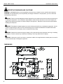
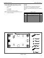
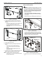
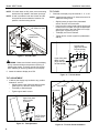
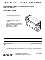
INSTALLATION INSTRUCTIONS
MEDIUM FLAT PANEL TILT WALL MOUNT WITH
INTEGRATED CPU
Model: MWC Series
Specifications:
•
Accommodates three installation options:
- Dual Wood Stud (16" on-center; requires
5/16" x 2-1/2" long hex head lag screws included)
- Dual Steel Stud (requires Chief PAC-115
Steel Stud / Drywall Anchor Kit - not included)
- Drywall (1/2" minimum; requires Chief PAC115 Steel Stud / Drywall Anchor Kit - not
included)
•
•
•
Accommodates CPU up to approximately 18-3/4"
x 3-3/4"; see "DIMENSIONS" for specific details.
Infinite display tilt adjustment between 0-15° with
positive stops at 0°, 5°, 10°, and 15°.
Weight capacity of 100 lbs (45 kg).
NOTE: Requires display interface providing 200x200mm
mounting button pattern; not included.
BEFORE YOU BEGIN
WARNING: It is the installer’s responsibility to make sure all components are properly assembled and installed
using the instructions provided. Failure to read, thoroughly understand, and follow all instructions can result in
serious personal injury, damage to equipment, or voiding of factory warranty.
•
If you have any questions about this these instructions or your specific installation, contact Chief Manufacturing
at 1-800-582-6480 or 952-894-6280.
CHIEF MANUFACTURING INC.
1-800-582-6480 952-894-6280 FAX 952-894-6918
8401 EAGLE CREEK PARKWAY, STE 700
SAVAGE, MINNESOTA 55378 USA
8804-000296 RevB
2007 Chief Manufacturing
www.chiefmfg.com
10/07
Model: MWC Series
Installation Instructions
IMPORTANT WARNINGS AND CAUTIONS!
WARNING: A WARNING alerts you to the possibility of serious injury or death if you do not follow the instructions.
CAUTION: A CAUTION alerts you to the possibility of damage or destruction of equipment if you do not follow the
corresponding instructions.
WARNING: Failure to provide adequate structural strength for this component can result in serious personal injury
or damage to equipment! It is the installer’s responsibility to make sure the structure to which this component is
attached can support five times the combined weight of all equipment. Reinforce the structure as required before
installing the component.
WARNING: Exceeding the weight capacity can result in serious personal injury or damage to equipment! It is the
installer’s responsibility to make sure the combined weight of all components attached to the MWC Series Wall
Mount, including the CPU and display, does not exceed 100 lbs (45 kg).
WARNING: Make sure the latch securing the display is fully closed at all times except when removing or installing
the display. The latch must be fully closed when installing or removing cables from the display.
WARNING: Allowing any part of your body or component cables to be caught between movable parts can result in
serious personal injury or damage to equipment!
DIMENSIONS
2
Installation Instructions
Model: MWC Series
TOOLS REQUIRED FOR INSTALLATION
•
•
•
•
•
PARTS
After unpacking carton, inspect and verify contents
(See Figure 1). If any listed parts are missing or
damaged, contact Chief Customer Service at 1-800-5826480.
Stud Sensor
Drill
5/32" Drill Bit
1/2" Wrench
5/32" Security Hex Key (included)
NOTE: Other tools may be required depending on your
method of installation.
Table 1: Parts
Item
Description
Qty
10
MOUNT, MWC Series
1
20
STRAP, 1" x 6’ Polypropylene with Cam Buckle
1
30
SCREW, Button Head Security, 1/4"-20 x 1/2"
4
40
SCREW, Button Head Cap, 1/4"-20 x 1/2"
2
50
NUT, Hex, Standard, 1/4"-20
2
60
KEY, Security Hex, 5/32"
1
70
SCREW, Hex Head Lag, 5/16 x 2-1/2"
4
80
WASHER, Flat, 5/16"
4
10
20
30
40
50
60
70
80
Figure 1: Parts
3
Model: MWC Series
Installation Instructions
INSTALLATION
CPU INSTALLATION
MOUNT INSTALLATION
Three installation options exist:
•
•
•
Dual Wood Stud (16" on-center; requires 5/16" x
2-1/2" long hex head lag screws)
Dual Steel Stud (requires Chief PAC-115 Steel
Stud / Drywall Anchor Kit; not included)
Drywall (1/2" minimum; requires Chief PAC-115
Steel Stud / Drywall Anchor Kit; not included)
The following instructions are for dual wood stud
installation. See instructions included with PAC-115 for
dual steel stud or drywall installation.
WARNING: Exceeding the weight capacity can result
in serious personal injury or damage to equipment! It is
the installer’s responsibility to make sure the combined
weight of all components attached to the MWC Series
Wall Mount, including the CPU and display, does not
exceed 100 lbs (45 kg).
1. Using key (60) remove and retain upper front plate
attach screws and washers (See Figure 3).
NOTE: Lower front plate attach screws may remain
installed.
1. Determine approximate mounting location, keeping in
mind the display size.
2. Use a stud sensor to locate applicable wood studs.
Mark locations with a pencil.
Front
Plate
3. Level mount at desired height. Using mount as a
template, mark the location of four pilot holes. Ensure
marks are in the center of wood studs.
Upper front plate
attach screws and
washers (2 places)
4. Drill pilot holes using a 7/32" drill bit. Ensure pilot
holes are straight.
5. Using 1/2" wrench, install four 5/16" x 2-1/2" hex head
lag screws (70) and four 5/16" washers (80) through
the mounting slots in the side plates into the pilot
holes (See Figure 2). Tighten all lag screws.
NOTE: Drywall not
shown for clarity.
Side Plates
Figure 3: Upper Front Plate Attach Screws
2. Tilt front plate away from wall and then lift out of lower
front plate attach screws (See Figure 4). Place front
plate on protective surface.
2
(80) x 4
(70) x 4
1
Figure 2: Mount Installation
Lower front
plate attach
screws
(2 places)
Front Plate
Figure 4: Remove Front Plate
3. Loosely thread strap (20) through side plates so that
buckle is in front (See Figure 5).
4
Installation Instructions
Model: MWC Series
DISPLAY INSTALLATION
Side Plates
20
WARNING: Exceeding the weight capacity can result
in serious personal injury or damage to equipment! It is
the installer’s responsibility to make sure the combined
weight of all components attached to the MWC Series
Wall Mount, including the CPU and display, does not
exceed 100 lbs (45 kg).
1. Install interface (providing 200x200mm mounting
button pattern) to display. See instructions supplied
with interface.
2. Rotate Q-Latch to the OPEN position (See Figure 7).
Figure 5: Install Strap
4. Carefully slide CPU between strap (20) and rear
surface of side plates (See Figure 6). Ensure the
following:
•
•
OPEN
Both loops of strap (20) are in front of the CPU; do
not wrap strap (20) around back of CPU.
CPU is positioned so that cooling vents are not
obstructed.
Q-Latch
Figure 7: Open Q-Latch
3. Lift and maneuver display so that all four mounting
buttons fit into button openings on front plate. Lower
display firmly into place. Ensure each button has fully
seated in its button opening (See Figure 8).
Mounting buttons
(4 places)
CPU
Button Openings
(4 places)
Figure 6: Insert CPU
5. Tighten strap (20) securely.
6. Re-install front plate by reversing the procedure in
Step 2:
•
•
•
Tilt the top of the front plate towards you.
Lower the front plate onto the lower attach
screws.
Tilt the top of the front plate away from you
(towards the wall).
7. Using key (60), re-install the retained upper front plate
attach screws and washers removed in Step 1.
NOTE: If desired, security screws (30) may be
substituted for non-security screws at both upper
and lower attach points.
Front Plate
NOTE: Display and
interface not shown for clarity.
Figure 8: Align and Lower Display
4. Rotate Q-Latch to the CLOSED position (See Figure
9).
5
Model: MWC Series
Installation Instructions
NOTE: If Q-Latch does not fully close, ensure mounting
buttons are fully seated in the button openings.
TILT LOCK
NOTE: A hole is provided in both the Q-Latch and the
front plate to accommodate the insertion of a
padlock or similar locking device.
NOTE: A positive stop exists at 15° without the use of an
additional locking screw.
NOTE: Display and interface
not shown for clarity.
Locking device
installed here
1. If desired, the display may be locked at 0°, 5°, or 10°.
•
•
•
•
Slightly loosen the upper front plate attach
screws. Do NOT remove screws.
Using key (60), loosely install screws (40) through
the slot in the front plate, through the applicable
open tilt lock hole in the side plate, into nut (50)
(See Figure 11)(See Figure 12).
Tilt display until lock is reached.
Tighten all four screws (upper front plate attach,
and 40).
Tilt lock holes
(Right side shown;
left side similar)
Q-Latch
CLOSED
10°
5°
0°
Figure 9: Close Q-Latch
WARNING: Make sure the latch securing the display
is fully closed at all times except when removing or
installing the display. The latch must be fully closed
when installing or removing cables from the display.
Upper front plate
attach screws
(Right side shown;
left side similar)
5. Attach all cables to display and CPU.
Figure 11: Tilt Lock Holes
TILT ADJUSTMENT
1. If desired, the display may be tilted to any position
between 0° and 15°.
• Slightly loosen upper front plate attach screws
(See Figure 10). Do NOT remove screws.
• Tilt display to desired angle.
• Tighten upper attach screws.
50 (2 places)
40 (2 places)
Upper front plate
attach screws
(2 places)
Side plate
Front plate
NOTE: Display
shown at 15°
position.
Figure 10: Tilt Adjustment
6
Figure 12: Tilt Lock Screw Installation