1
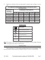
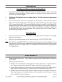
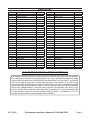
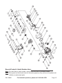
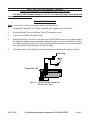
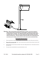
4’’ DRY TILE SAW
Model 38941
ASSEMBLY AND OPERATION INSTRUCTIONS
Diamond Blade not included; sold separately.
Due to continuing improvements, actual product may differ slightly from the product described herein.
Distributed Exclusively by Harbor Freight Tools
3491 Mission Oaks Blvd., Camarillo, CA 93011
Visit our website at: http://www.harborfreight.com
TO PREVENT SERIOUS INJURY, READ AND UNDERSTAND
ALL WARNINGS AND INSTRUCTIONS BEFORE USE.
Copyright© 1998, 2006 by Harbor Freight Tools®. All rights reserved. No portion of this
manual or any artwork contained herein may be reproduced in any shape or form without
the express written consent of Harbor Freight Tools.
For technical questions or replacement parts, please call 1-800-444-3353.
REV 09e
SPECIFICATIONS
Motor
110 V~, 3.2 A (No Load)
Cutting Capacity
1-3/8”
RPM
10,525
Blade (sold separately)
4” Diameter x 5/8” Arbor
Overall Dimensions
Overall Weight
#230373
9” x 7” x 7-3/4”
Motor is double insulated
7.6 lb.
The Tile Saw comes with an Arbor wrench and a T-Handle Wrench. A Blade is not included
with the Tile Saw and must be purchased separately. Recommended saw blade is item #34441
- 4” Diamond blade-Dry type. Saw blades are available at Harbor Freight Tools.
Save This Manual
You will need this manual for the safety warnings and precautions, assembly, operating,
inspection, maintenance and cleaning procedures, parts list and assembly diagram. Keep your
invoice with this manual. Write the invoice number on the inside of the front cover. Write the
product’s serial number in the back of the manual near the assembly diagram, or write month
and year of purchase if product has no number. Keep this manual and invoice in a safe and dry
place for future reference.
Wet Cut Attachment
A Wet Cut Attachment (Item 38942) is also available through Harbor Freight Tools. This
attachment is not included with the Dry Tile Saw.
If you have purchased the Wet Cut Attachment (#38942) please see the assembly and
operating instructions for this attachment on page #8. Recommended blade when using the Wet
Cut attachment is item #34310 - 4” Diamond blade-Wet type (Continuous Rim Design).
GENERAL SAFETY RULES
WARNING!
READ AND UNDERSTAND ALL INSTRUCTIONS
Failure to follow all instructions listed below may result in
electric shock, fire, and/or serious injury.
SAVE THESE INSTRUCTIONS
WORK AREA
1.
Keep your work area clean and well lit. Cluttered benches and dark areas invite accidents.
REV 08/01; 09e
SKU 38941
For technical questions, please call 1-800-444-3353.
Page 2
2.
Do not operate power tools in explosive atmospheres, such as in the presence of
flammable liquids, gases, or dust. Power tools create sparks which may ignite the dust
or fumes.
3.
Keep bystanders, children, and visitors away while operating a power tool. Distractions can cause you to lose control. Protect others in the work area from debris such as
chips and sparks. Provide barriers or shields as needed.
ELECTRICAL SAFETY
1.
Double insulated tools are equipped with a polarized plug (one blade is wider than
the other). This plug will fit in a polarized outlet only one way. If the plug does
not fit fully in the outlet, reverse the plug. If it still does not fit, contact a qualified
electrician to install a polarized outlet. Do not change the plug in any way. Double
insulation
eliminates the need for the three wire grounded power cord and grounded
power supply system.
2.
Avoid body contact with grounded surfaces such as pipes, radiators, ranges, and
refrigerators. There is an increased risk of electric shock if your body is grounded.
3.
Do not expose power tools to rain or wet conditions. Water entering a power tool will
increase the risk of electric shock. Only use correct wet cut attachment for wet cutting.
4.
Do not abuse the Power Cord. Never use the Power Cord to carry the tools or pull
the Plug from an outlet. Keep the Power Cord away from heat, oil, sharp edges, or
moving parts. Replace damaged Power Cords immediately. Damaged Power Cords
increase the risk of electric shock.
5.
When operating a power tool outside, use an outdoor extension cord marked “W-A”
or “W”. These extension cords are rated for outdoor use, and reduce the risk of electric
shock.
PERSONAL SAFETY
1.
Stay alert. Watch what you are doing, and use common sense when operating a
power tool. Do not use a power tool while tired or under the influence of drugs,
alcohol, or medication. A moment of inattention while operating power tools may result
in serious personal injury.
2.
Dress properly. Do not wear loose clothing or jewelry. Contain long hair. Keep your
hair, clothing, and gloves away from moving parts. Loose clothes, jewelry, or long hair
can be caught in moving parts.
3.
Avoid accidental starting. Be sure the Power Switch is off before plugging in. Carrying power tools with your finger on the Power Switch, or plugging in power tools with the
Power Switch on, invites accidents.
4.
Remove adjusting keys or wrenches before turning the power tool on. A wrench or a
key that is left attached to a rotating part of the power tool may result in personal injury.
SKU 38941
For technical questions, please call 1-800-444-3353.
Page 3
5.
Do not overreach. Keep proper footing and balance at all times. Proper footing and
balance enables better control of the power tool in unexpected situations.
6.
Use safety equipment. Always wear eye protection. Dust mask, nonskid safety shoes,
hard hat, or hearing protection must be used for appropriate conditions. Always wear
ANSI-approved safety goggles and a dust mask/respirator when using or performing
maintenance on this tool.
TOOL USE AND CARE
1.
Use clamps (not included) or other practical ways to secure and support the workpiece to a stable platform. Holding the work by hand or against your body is unstable
and may lead to loss of control.
2.
Do not force the tool. Use the correct tool for your application. The correct tool will
do the job better and safer at the rate for which it is designed. Do not force the tool and
do not use the tool for a purpose for which it is not intended.
3.
Do not use the power tool if the Power Switch does not turn it on or off. Any tool that
cannot be controlled with the Power Switch is dangerous and must be replaced.
4.
Disconnect the Power Cord Plug from the power source before making any adjustments, changing accessories, or storing the tool. Such preventive safety measures
reduce the risk of starting the tool accidentally. Always unplug the tool from its electrical
outlet before performing any inspection, maintenance, or cleaning procedures.
5.
Store idle tools out of reach of children and other untrained persons. Tools are dangerous in the hands of untrained users.
6.
Maintain tools with care. Keep cutting tools sharp and clean. Properly maintained
tools with a sharp cutting edge are less likely to bind and are easier to control. Do not use
a damaged tool. Tag damaged tools “Do not use” until repaired.
7.
Check for misalignment or binding of moving parts, breakage of parts, and any other
condition that may affect the tool’s operation. If damaged, have the tool serviced
before using. Many accidents are caused by poorly maintained tools.
8.
Use only accessories that are recommended by the manufacturer for your model.
Accessories that may be suitable for one tool may become hazardous when used on another tool.
SERVICE
1.
Tool service must be performed only by qualified repair personnel. Service or maintenance performed by unqualified personnel could result in a risk of injury.
2.
When servicing a tool, use only identical replacement parts. Follow instructions
in the “Inspection, Maintenance, And Cleaning” section of this manual. Use of unauthorized parts or failure to follow maintenance instructions may create a risk of electric
shock or injury.
SKU 38941
For technical questions, please call 1-800-444-3353.
Page 4
SPECIFIC SAFETY RULES
1.
Maintain labels and nameplates on the tool. These carry important information. If
unreadable or missing, contact Harbor Freight Tools for a replacement.
2.
Maintain a safe working environment. Make sure there is adequate surrounding workspace. Do not use this product in a damp or wet location.
3.
Avoid unintentional starting. Make sure you are prepared to begin work before turning
on the tool.
4.
Always keep the extension cord away from moving parts on the tool.
5.
People with pacemakers should consult their physician(s) before using this product.
Electromagnetic fields in close proximity to a heart pacemaker could cause interference
to or failure of the pacemaker. In addition, people with pacemakers should adhere to the
following:
• Avoid operating power tools alone.
• Don’t use a power tool with the power switch locked on.
• If powered via a power cord be certain that the tool is properly grounded. A ground fault
interrupt (GFCI) system is also a good precaution. This inexpensive device is a good
safety measure because it prevents a sustained electrical shock.
• Properly maintain and inspect all tools before use to avoid electrical shock.
6.
Never leave the tool unattended when it is plugged into an electrical outlet. Turn off
the tool, and unplug it from its electrical outlet before leaving.
7.
WARNING: Some dust created by power sanding, sawing, grinding, drilling, and
other construction activities, contains chemicals known [to the State of California]
to cause cancer, birth defects or other reproductive harm. Some examples of these
chemicals are:
Lead from lead-based paints
Crystalline silica from bricks and cement or other masonry products
Arsenic and chromium from chemically treated lumber
Your risk from these exposures varies, depending on how often you do this type of work.
To reduce your exposure to these chemicals: work in a well ventilated area, and work with
approved safety equipment, such as those dust masks that are specially designed to filter
out microscopic particles. (California Health & Safety Code § 25249.5, et seq.)
SKU 38941
For technical questions, please call 1-800-444-3353.
Page 5
GROUNDING
Outlets for 2-Prong Plug
DOUBLE INSULATED TOOLS: TOOLS WITH TWO PRONG PLUGS
1.
Tools marked “Double Insulated” do not require grounding. They have a special double
insulation system which satisfies OSHA requirements and complies with the applicable
standards of Underwriters Laboratories, Inc., the Canadian Standard Association, and the
National Electrical Code. (See Outlets for 2-Prong Plug.)
2.
Double insulated tools may be used in either of the 120 volt outlets shown in the preceding
illustration. (See Outlets for 2-Prong Plug.)
EXTENSION CORDS
1.
Double Insulated tools can use either a two or three wire extension cord.
2.
As the distance from the supply outlet increases, you must use a heavier gauge extension
cord. Using extension cords with inadequately sized wire causes a serious drop in voltage,
resulting in loss of power and possible tool damage. (See Table A.)
3.
The smaller the gauge number of the wire, the greater the capacity of the cord. For example, a 14 gauge cord can carry a higher current than a 16 gauge cord.
(See Table A.)
4.
When using more than one extension cord to make up the total length, make sure each
cord contains at least the minimum wire size required. (See Table A.)
5.
If you are using one extension cord for more than one tool, add the nameplate amperes
and use the sum to determine the required minimum cord size.
(See Table A.)
6.
If you are using an extension cord outdoors, make sure it is marked with the suffix “W-A”
(“W” in Canada) to indicate it is acceptable for outdoor use.
7.
Make sure your extension cord is properly wired and in good electrical condition. Always
replace a damaged extension cord or have it repaired by a qualified electrician before
using it.
SKU 38941
For technical questions, please call 1-800-444-3353.
Page 6
8.
Protect your extension cords from sharp objects, excessive heat, and damp or wet areas.
RECOMMENDED MINIMUM WIRE GAUGE FOR EXTENSION CORDS*
(120 OR 240 VOLT)
NAMEPLATE
AMPERES
(at full load)
0 – 2.0
2.1 – 3.4
3.5 – 5.0
5.1 – 7.0
7.1 – 12.0
12.1 – 16.0
16.1 – 20.0
TABLE A
EXTENSION CORD LENGTH
25 Feet
50 Feet
75 Feet
100 Feet
150 Feet
18
18
18
16
14
18
18
18
18
14
12
18
18
16
14
12
10
18
16
14
12
10
18
14
12
10
-
-
16
12
12
-
* Based on limiting the line voltage drop to five volts at 150% of the rated amperes.
SYMBOLOGY
Double Insulated
Canadian Standards Association
Underwriters Laboratories, Inc.
V~
A
Volts Alternating Current
Amperes
n0 xxxx/min. No Load Revolutions per Minute (RPM)
Note: Performance of this tool may vary depending on variations in local line voltage. Extension
cord usage may also affect tool performance.
UNPACKING
When unpacking your Tile Saw make sure that the item is intact and undamaged. If any
parts are missing or broken, please call HARBOR FREIGHT TOOLS at 1-800-444-3353.
SKU 38941
For technical questions, please call 1-800-444-3353.
Page 7
OPERATION
Installing and Removing the Cutting Blade
1.
Your Tile Saw comes with an arbor wrench and a T-Handle socket wrench for use when
installing or removing a Blade. When installing or removing a blade, always make sure
the tool is OFF and unplugged.
2.
A Diamond Cutting Blade is not included with the Tile Saw and must be purchased
separately.
3.
Turn the Tile Saw so that you are looking at the Blade wheel. Place the arbor wrench
(58) on the Outside Flange (2) to hold the flange in place while using the socket wrench
(59) to loosen the Hex Bolt. Remove the Blade by sliding it up and off of the Spindle (8).
When mounting the blade, observe the rotation direction arrows, and slide the blade onto
the Spindle making sure that it fits snugly. Refer to the Blade manufacturer’s guidelines
for specifications, proper use and warnings. With blade in place, hold Outside Flange in
place while tightening the Hex Bolt.
Using the Saw
1.
Grip the Handle (30) with your index finger on the trigger switch and depress the trigger
switch to start the saw.
2.
Apply firm and steady pressure to the Saw during use. DO NOT FORCE SAW.
Note: The Saw has a HOLD BUTTON to maintain constant speed and reduce fatigue. To lock
this button into the ON position, depress the Trigger Switch then press the Hold Button and
release pressure on the Trigger Switch. To RELEASE the HOLD BUTTON, lightly depress
the Trigger Switch.
MAINTENANCE
1.
Always keep the Saw clean. The ventilation passage should be kept clean and free from
obstructions.
2.
Replacing Carbon Brushes:
a. Replace the Carbon Brushes when they wear down to about 3/16” or sparking will occur. Always change both brushes (43) (upper and lower) at the same time.
b. Using a flat tip screwdriver, unscrew (counter-clockwise) the Brush Caps (Black plastic
plug) (44) on the Enclosure (36). Remove them from the Brush Holders (42).
c. Replace the Carbon Brushes with identical replacement parts from Harbor Freight Tools.
Insert the Brushes into the Brush Holder, and insert back into the Enclosure. Screw
back in the Brush Cap and tighten.
REV 09e
SKU 38941
For technical questions, please call 1-800-444-3353.
Page 8
PARTS LIST
Part
1
2
3
4
5
6
7
8
9
10
11
12
13
14
15
16
17
18
19
20
21
22
23
24
25
26
27
28
29
30
Description
Hex Bolt
Outside Flange
Inside Flange
Screw M4 x 8
Elastic Washer 4
Bearing Cover
O Sealing Ring
Spindle
Woodruff Key 3 x 13
Bearing
Elastic Distance Ring
Screw M4 x 25
Elastic Washer -4
Gear Box Cover
No. 2 Gear
Needle Bearing
Middle Cover
No. 1 Gear
Bearing
Woodruff Key 2.5 x 10
Fan
Armature
Distance Ring
Bearing
Screw 5x65
Spring Washer - 5
Stator
Washer
O Sealing Ring
Handle Cover
Quantity
1
1
1
3
3
1
1
1
1
1
1
4
4
1
1
1
1
1
1
1
1
1
1
1
2
2
1
1
1
1
Part
31
32
33
34
35
36
37
38
39
40
41
42
43
44
45
46
47
48
49
50
51
52
53
54
55
56
57
58
59
501
Description
Air Guide
Screw 4 x 16
Cord Cup
Switch Sleeve
Switch
Enclosure
Screw 4 x 20
Nameplate
Washer 5
Spring washer 5
Screw M5 x 40
Brush holder
Brush
Brush cap
Cord
Cord armor
Base
Thumb bolt
Spring washer
Washer
Clip
Water tube
Elastic pin 6 x 30
Distance ring
Thumb bolt
PVC tube
Adapter
Wrench
Socket wrench
Blade/ not included
Quantity
1
1
1
1
1
1
4
1
3
3
3
2
2
2
1
1
1
1
1
1
1
1
1
1
1
1
1
1
1
0
PLEASE READ THE FOLLOWING CAREFULLY
THE MANUFACTURER AND/OR DISTRIBUTOR HAS PROVIDED THE PARTS LIST AND ASSEMBLY DIAGRAM IN THIS MANUAL AS A REFERENCE TOOL ONLY. NEITHER THE MANUFACTURER
OR DISTRIBUTOR MAKES ANY REPRESENTATION OR WARRANTY OF ANY KIND TO THE BUYER
THAT HE OR SHE IS QUALIFIED TO MAKE ANY REPAIRS TO THE PRODUCT, OR THAT HE OR
SHE IS QUALIFIED TO REPLACE ANY PARTS OF THE PRODUCT. IN FACT, THE MANUFACTURER
AND/OR DISTRIBUTOR EXPRESSLY STATES THAT ALL REPAIRS AND PARTS REPLACEMENTS
SHOULD BE UNDERTAKEN BY CERTIFIED AND LICENSED TECHNICIANS, AND NOT BY THE
BUYER. THE BUYER ASSUMES ALL RISK AND LIABILITY ARISING OUT OF HIS OR HER REPAIRS
TO THE ORIGINAL PRODUCT OR REPLACEMENT PARTS THERETO, OR ARISING OUT OF HIS
OR HER INSTALLATION OF REPLACEMENT PARTS THERETO.
SKU 38941
For technical questions, please call 1-800-444-3353.
Page 9
Record Product’s Serial Number Here:
Note: If product has no serial number, record month and year of purchase instead.
Note: Some parts are listed and shown for illustration purposes only, and are not available individually as replacement parts.
SKU 38941
For technical questions, please call 1-800-444-3353.
Page 10
WET CUT ATTACHMENT (38942)
(Please order separately- not included with the 4” Dry Tile Saw)
The Wet Cut Attachment includes a 1/4” I.D. x 9.5 foot vinyl hose, water plug with
screw and rubber connector
Assembly Instructions
Note: In step one (1) do not completely remove the Thumb Bolt.
1.
Loosen the Thumb Bolt (55), lower the guide, and re-tighten the Thumb Bolt.
2.
Attach the Water Plug to the Water Tube (52) using the screw.
3.
Connect the HOSE to the Water Plug.
4.
Attach the Rubber Connector to the other end of the HOSE and connect to a water supply.
An additional adapter may be needed between the water source and the Rubber Connector. Water may also be fed to the unit by gravity feed when a water line is not assessable.
See the Gravity Feed instructions on the next page.
5.
Turn water valve on the Water Plug counterclockwise to open and clockwise to close.
Water Plug
Thumb Bolt (55)
Figure 4 — Attaching the Water Supply Unit
(Tile Saw - Rear View)
SKU 38941
For technical questions, please call 1-800-444-3353.
Page 11
Warning: When using the Wet Cutting Attachment, extreme care must be taken to
insure that the saw’s electrical cord is positioned to remain dry and free from
the water hose at all times. The operator must be aware that an extreme electrical hazard can occur if the cord, or the operator becomes wet while using this
electric powered tool. Care and common sense must be used in planning a safe
work area and in finding a safe location for the water bucket described below.
Gravity Feed Instructions
1.
Place a large bucket of water on a stable platform at least five feet above the working area (see above).
2.
Remove the hose from the Water Plug. Insert one end of the Hose into the bucket of water so that it is well
under the top of the water level.
3.
Suck on the other end of the Hose until water can be seen flowing down the hose. Reconnect the hose to
the Water Plug.
4.
Turn water valve counterclockwise to open and clockwise to close.
SKU 38941
For technical questions, please call 1-800-444-3353.
Page 12
90 Day Warranty
Harbor Freight Tools Co. makes every effort to assure that its products meet high quality and
durability standards, and warrants to the original purchaser that this product is free from defects in materials and workmanship for the period of 90 days from the date of purchase. This
warranty does not apply to damage due directly or indirectly, to misuse, abuse, negligence
or accidents, repairs or alterations outside our facilities, criminal activity, improper installation, normal wear and tear, or to lack of maintenance. We shall in no event be liable for death,
injuries to persons or property, or for incidental, contingent, special or consequential damages
arising from the use of our product. Some states do not allow the exclusion or limitation of incidental or consequential damages, so the above limitation of exclusion may not apply to you.
THIS WARRANTY IS EXPRESSLY IN LIEU OF ALL OTHER WARRANTIES, EXPRESS OR
IMPLIED, INCLUDING THE WARRANTIES OF MERCHANTABILITY AND FITNESS.
To take advantage of this warranty, the product or part must be returned to us with transportation charges prepaid. Proof of purchase date and an explanation of the complaint must accompany the merchandise. If our inspection verifies the defect, we will either repair or replace the
product at our election or we may elect to refund the purchase price if we cannot readily and
quickly provide you with a replacement. We will return repaired products at our expense, but if
we determine there is no defect, or that the defect resulted from causes not within the scope of
our warranty, then you must bear the cost of returning the product.
This warranty gives you specific legal rights and you may also have other rights which vary
from state to state.
3491 Mission Oaks Blvd. • PO Box 6009 • Camarillo, CA 93011 • (800) 444-3353
SKU 38941
For technical questions, please call 1-800-444-3353.
Page 13