1
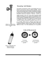
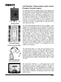
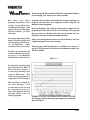
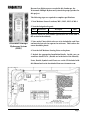
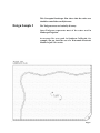
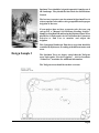
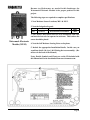
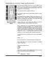
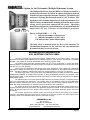
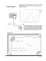
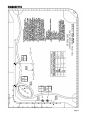
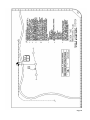
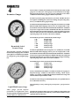
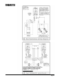
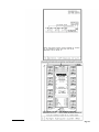
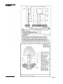
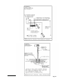
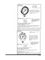
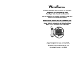
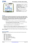
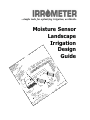
...simple tools for optimizing irrigation, worldwide.
Moisture Sensor
Landscape
Irrigation
Design
Guide
Foreword
Since 1951 Irrometer Company, Inc. has provided simple tools that
help answer the age old questions:
When should I irrigate? (How often)
and
How long should I irrigate? (Cycle Run Time)
The need for knowing how to answer these two questions for proper
scheduling is even more important today than it was in 1951. The
conservation and protection of our valuable water resources is an
important consideration in design criteria today. Proper soil
moisture measurement and control can help maximize your
irrigation system’s efficiency by allowing water to be applied only
WHEN and WHERE it is needed. Such soil moisture automation of
any 24 Volt AC control system is easily accomplished with the Irrometer family of products.
Many moisture sensing products have come and gone over the
years, but Irrometer Company, Inc. continues to be synonymous
with quality, high value products. You can be confident they will
enhance your designs and maximize your client’s irrigation system
efficiency.
This manual will introduce you to some of our products. We also
talk about some typical applications and illustrate how our
moisture sensing products can be specified in some example
projects. This manual does not show every application but feel free
to call us to discuss your particular project needs.
Sample details in AutoCAD format are included on the enclosed
CD, inside the back cover, for your convenience.
Lastly, when you specify a project with our products, we would be
happy to send the installer and end user training materials.
Please inform us who to contact, if necessary.
For more information, contact The Irrometer Co., Inc at:
Phone:
(951) 689-1701
Fax:
(951) 689-3706
URL:
www.irrometer.com
E-mail:
[email protected]
or
[email protected]
Information contained in this manual is based on generally accepted information and practices. If any problems, difficulties,
or injury arise from or in connecion with the use of this information, or if there is any error herein, typographical or otherwise,
Irrometer Company, Inc., and its agents or employees thereof , shall not be responsible or liable therefor.
Foreword
Contents
1
What is Soil Moisture Measurement and Control?.......1
Soil/Water/Plant Relationships........................................1
Measuring Soil Moisture.................................................2
Soil Moisture Measurement and Control Products........3
2
3
Why use Soil Moisture Measurement and
Control Products from Irrometer?..................................4
Design One Example.......................................................6
Design Two Example.......................................................8
Design Three Example..................................................10
Multiple Hydrozone System
Part Number Specification Details................................12
Submittal information.....................................................14
Monitor............................................................................15
Design Four Example ....................................................16
Sample Design Plans......................................................17
4
Pressure Gauges............................................................21
5
Detail Drawings..............................................................22
CD..........................................................inside back cover
Contents
1
What is Soil Moisture Measurement
and Control?
Before we talk about specifics, let us take a step back and look
at the living system in which we will be working.
The Soil, Water, Plant System
Evapotranspiration moves water out of the system and rain or
irrigation replaces it. The soil provides storage for the water.
Typically, the plant removes water according to the chart below.
Water is pulled by the roots into the plant. The soil is attracting
the water as well. This competition between the plant and soil
for the water creates tension. As the water is depleted by the
plant, it first takes the water that is most easily released and
continues to take water that is more and more tightly held by the
soil. This tension can be measured by soil moisture measurement
instruments. The higher the tension created, the harder it is for
the plant to extract water from the soil. Eventually there will be
no more “available water” for the plant. Most landscape plants
suffer from just the opposite, no oxygen in the soil because of too
much water.
In most cases, the ideal situation would be to irrigate until the
root zone approaches saturation. Next, allow it to dry out to a
reasonable level before irrigating again. This allows the soil to
“BREATHE” oxygen in, which is good for both the plant and soil
organisms. It also helps minimize the impact of insect and
disease problems.
Page 1
Measuring Soil Moisture
Figure 1-1 Irrometer Low
Tension Tensiometer Model
“LT”
Soil moisture measurement consists of determining the level of
moisture in the soil by a direct or indirect method. Control
involves interpreting the measurements and taking the action or
actions that are most beneficial. One direct method is accomplished
by using a device called a tensiometer. (Figure 1-1) This sensitive
instrument measures the amount of “tension”, “suction” or
negative pressure in the soil. It uses units of pressure called
centibars or kilo-pascals. One centibar is one hundredth of a bar.
One bar is about 14.7 pounds per square inch (psi). So when you see
a gauge that reads from 0-100 cb (centibars) it is roughly the same
as reading 0-14.7 psi in negative pressure or suction.
An indirect method of measuring soil moisture tension is by way
of a Granular Matrix Sensor, called the Watermark from
Irrometer Company, Inc. (Figure 1-2). This product is calibrated to
a Tensiometer and has a range of 0-200 cb. Wire can be run up to
1000 feet or more. It is a low maintenance, low cost product.
Units of Measurement
15 psi gauge
measures positive
pressure
100cb/kPa gauge
measures negative
pressure
Figure 1-2 Watermark Soil
Moisture Sensor by
Irrometer Company
Page 2
Soil Moisture Measurement and Control
Products from Irrometer
Watermark Electronic
Module (WEM)
Watermark Multiple
Hydrozone System (MHS)
Watermark Electronic
Meter (30-KTCD-NL)
Watermark Monitor
The Watermark Electronic Module (WEM) comes complete with
two Watermark Sensors and an Installation and Operation Manual.
It is designed to interface with 24 VAC Controllers or Valves.
Individual valves can be controlled by installing sensors in the
area irrigated by the same valve. It is fully adjustable from wet to
dry and has an “OFF” position to override the sensor. It is water
proof for valve box installation or can be installed at the
controller. It can override a valve group on a separate common
or the entire controller. Irrigation will occur only when soil is
dryer than the set point.
The Watermark Multiple Hydrozone System (MHS) comes
complete with Watermark Sensors, Watermark Electronic
Modules and an Installation/Operating Manual. It provides up
to eight independent moisture sensing locations used to control
the valves by “group” based on common irrigation need, on a
single common wire. There is no need for separate commons
with the MHS. Each moisture sensing location can be
independently adjusted for desired moisture level. System
Bypass Switch provides for override of sensors at the panel. LED’s
on panel aid in checking system operation. Additional
Jumper Cables can be added to accomodate an unlimited
number of valves per group. Irrigation will occur only when soil is
dryer than the user defined set point. Can be mounted in the
irrigation controller enclosure or is available in its own
stainless steel enclosure.
The Watermark Meter is a solid state alternating current
resistance bridge meter for reading Watermark Sensors.
It is adjustable for soil temperature variations. This is a portable
and useful tool for manually reading sensors. One meter is
required to read an unlimited number of sensors, one at a time.
The Meter includes: touch pad operating panel, durable case and
field changeable cable assembly. Read from 0cb, WET to 199cb,
Very Dry.
The Watermark Monitor is a data-logging device that
automatically records soil moisture readings. This data is
periodically downloaded for graphical display on a computer, so
the irrigation manager can get a vivid illustration of the effects of
their irrigation scheduling. The Monitor can record up to eight
sensors, either soil moisture, soil temperature and/or dry contact
switch closures.
Page 3
2
Why use Soil Moisture Measurement and
Control Products from Irrometer?
Conserving water, our most precious natural resource, is of great
importance. Good water management will also result in optimizing
pumping energy, as well as reprogramming labor.
More landscape plants die each year from over watering than from
under watering. In fact, Arborists tell us that most specimen tree
deaths are a result of improper watering. If you use specimen
trees in your projects you should protect these valuable
investments from overwatering and potential death. It is very
difficult to tell what the soil moisture is like under ground on large
trees without Moisture Sensors.
Many fill slope failures are caused by too much water in the soil.
This can be avoided by using Moisture Control Products.
Over irrigation can also leach landscape chemicals into water
supplies and out of the reach of
plant roots.
The soil moisture chart below shows research results of three
methods of irrigation. These results were from trials conducted by
experienced irrigation professionals.
Figure 2-1
Page 4
When you specify Watermark Soil Moisture Automation Products
in your design, your client receives many benefits.
Run times, start times,
programs and moisture level
settings are provided in the
recommended schedule. This
provides the user with a highly
efficient schedule for their
controller.
Irrometer offers software that enables the irrigation manager to
properly schedule their new irrigation system using the soil
moisture control equipment.
After performing a site audit, the information is input into the
program, which is a Microsoft® Excel® workbook. The program
then generates a schedule that the user programs into the
irrigation controller to obtain maximum efficiency.
Percentage adjustments can be
made for run times within each Many water management features are also included to allow the
valve grouping, or Hydrozone, irrigation manager to track water usage.
to accommodate slight
variations between valve zones. This program, called WaterPerfect, is available, at no charge, to
any user of Watermark Soil Moisture Automation products, the
Periodic site monitoring and WEM and MHS.
schedule adjustments may be
necessary to accommodate
individual site characteristics.
Figure 3-1
By manually inputting data
from water meters or bills, ET
data and water budgets, a
record is kept showing water
usage by Hydrozone. This
tracks system performance in
comparison to ET and budgets.
This reporting is valuable for
the water manager ’s own
records and can also be used
for reporting purposes for
water management districts
that may require it for cost
sharing programs.
Example of a curve from WaterPerfect software showing
water usage of a plant material group compared to actual and
historic ET data.
Page 5
3
Design Sample 1
How to Specify Soil Moisture
Measurement and Control Products.
This Conceptual Landscape Plan shows areas that should be
controlled by Hydrozone, according to the different water need
areas.
The Turfgrass areas are basically all sunny.
The Shrub areas away from slopes will be rooted deeper and
in most cases need less water than cool season grasses.
The top of slope areas typically use more water because of more
exposure to wind and the difficulty in irrigating them.
The bottom of slope areas are likely to require less water
because of drainage from the slope above and less wind.
Fill slopes can fail with overirrigation.
Page 6
Because four Hydrozones are needed in this Landscape, the
Watermark Multiple Hydrozone System is the proper product for
this project.
The following steps are required to complete specifications:
1. Note Moisture Sensor Locations, MS 1, MS 2, MS 3 & MS 4.
2. Note the Irrigation Legend:
Symbol
Manufacturer
Description
MS
Irrometer
Multiple Hydrozone System
Model
MHS
(Specific details for part number specification are at the back of
this section in the manual)
Watermark Multiple
Hydrozone System
(MHS)
3. Note on the Chart which valves are to be included in each Zone
and note the last valve in sequence in each zone. This is where the
sensor should be placed.
4. Note the Soil Moisture Sensing Notes on the plans.
5. Include the appropriate Installation Details. In this case you
would use details 1 & 6. (Details are in the back of the Manual)
Notes, Details, Symbols and Charts are on the CD included with
this Manual and can be downloaded from www.irrometer.com.
Page 7
This Conceptual Landscape Plan shows that the entire area
should be controlled as one Hydrozone.
Design Sample 2
The Turfgrass areas are basically all sunny.
Open Turfgrass represents most of the water used in
Landscape Irrigation.
An average five acre park in Southern California, for
example, can pay back the cost of a Watermark Electronic
Module in just a few weeks.
Page 8
Because one Hydrozone is needed in this Landscape, the
Watermark Electronic Module is the proper product.
The following steps are required to complete specifications:
1. Note Moisture Sensor Location, MS 1.
2. Note the Irrigation Legend:
Symbol
Manufacturer
Description
MS
Irrometer
Watermark Electronic Module
Model
WEM
3. Note on the Chart that all valves are to be included and note the
last valve in sequence. This is where the sensor should be placed.
4. Note the Soil Moisture Sensing Notes on the plans.
Watermark Electronic
Module (WEM)
5. Include the appropriate Installation Details. In this case you
would use details 1 & 3 . (Details are in the back of the Manual)
Notes, Details, Symbols and Charts are on the CD included with
this Manual and can be downloaded from www.irrometer.com.
Page 9
Specimen Trees should be irrigated separately from the rest of
the Landscape. They should also have their own Soil Moisture
Control.
The best way to protect your investment in Specimen Trees is
to have separate valves and or valve groups dedicated to proper
irrigation of the trees.
If your project does not have a separate valve for trees, you
can specify a “Manual Soil Moisture Reading Station.”
Simply by using Detail #8 and having the Moisture Sensor Wires
placed in a six inch round valve box will allow the Contractor,
Arborist or End User to monitor and adjust the
irrigation.
This Conceptual Landscape Plan shows areas that should be
controlled by Hydrozone, according to the different water need
areas.
Design Sample 3
The Specimen Trees are deeper rooted than the Turfgrass
areas and require “Precise Irrigation”. Ask for Irrometer
“Urban Tree” newsletter for additional information
The Turfgrass areas should be on their own zone.
Page10
Because two Hydrozones are needed in this Landscape, the
Watermark Electronic Module is the proper product for this
project.
The following steps are required to complete specifications:
1. Note Moisture Sensor Locations, MS 1 & MS 2.
2. Note the Irrigation Legend:
Symbol
Manufacturer
MS
Irrometer
Description
Watermark Electronic Module
Model
WEM
3. Note on the Chart which valves are to be included in each Zone
and note the last valve in sequence in each zone. This is where the
sensor should be placed.
Watermark Electronic
4. Note the Soil Moisture Sensing Notes on the plans.
Module (WEM)
5. Include the appropriate Installation Details. In this case you
would use details 1 & 4 (or 1 & 8 if doing the trees manually). (Details are in the back of the Manual)
Notes, Details, Symbols and Charts are on the CD included with
this Manual and can be downloaded from www.irrometer.com.
Page 11
Multiple Hydrozone System Part Number Specification Details
The Watermark Multiple Hydrozone System (MHS) can be
ordered as individual components to be assembled by the installer
or as a factory mounted and wired sub-assembly, ready to be
mounted in a control enclosure.
The components which comprise a MHS are:
The Multiple Hydrozone System Module (MHS), one per
controller.
Watermark Electronic Modules (WEM), one per Hydrozone, or
group of valves with like water demand (two Watermark
sensors are included with each WEM). Up to eight can be used
with the Multiple Hydrozone System.
Watermark Multiple
Hydrozone System
(MHS)
Jumper cables (JC), which connect the MHS to the 24 VAC
irrigation controller, one per irrigation zone (valve).
These components can be specified and ordered factory
assembled, to facilitate installation. The components will be
mounted on an aluminum backpanel and pre-wired so that the
installer need only make connections to the controller and field
sensor wires at labeled terminal strips. The entire assembly
measures 11” x 16” x 2” and can be easily mounted in a control
enclosure or on a wall, typically under or beside the controller.
To specify this factory assembled version, create a part number,
such as:
MHS- 4 - 18
The first number, here 4, denotes the number of Hydrozones
The second number, here 18, denotes the number or irrigation
zones or valves total
This system would consist of :
1 MHS
4 WEM
18 JC
and would be mounted on the backpanel and wired for terminal
strip connection like the picture in the margin.
MHS - ___________ - __________
# Hydrozones # Valves
Page 12
Cabinet Mounted Option for the Watermark Multiple Hydrozone System
The Multiple Hydrozone System (MHS) is available mounted in a
stainless steel enclosure for indoor or outdoor installation separate
from the irrigation controller enclosure, if desired. The stainless steel
enclosure is a Strong-Box® manufactured by V.I.T. Products. This
sturdy box with a lockable hinged door is easily wall mounted. The
MHS is factory mounted inside, standing off from the back, so that
wiring can be protected underneath the panel. Operating
instructions, and general system information, are attached inside the
hinged door for easy reference by maintenance personnel.
Specify as Model MHS- * - ** -CM
* indicates the number of Hydrozones
** indicates the number of total valves
CM indicates the Cabinet Mount option
The label below is attached inside the door of the enclosure for
informational purposes for the end user and any maintenance
personnel who may service the system.
WATERMARK MULTIPLE HYDROZONE SYSTEM
SOIL MOISTURE CONTROL PANEL
This panel automates the programmed irrigation schedule based on soil moisture status. This control
maximizes the irrigation system efficiency by only allowing irrigation to occur when the soil moisture is sufficiently
depleted. This provides for optimum plant health, while conserving irrigation water.
The irrigation valves have been grouped together into two or more “Hydrozones” or groups with similar
watering demand. Two Watermark soil moisture sensors are located in a representative area in the root zone of the
last valve to run in each grouping.
These sensors are wired back to this panel for each of the “Hydrozones.” Each “Hydrozone” is individually
adjustable by rotating the selector knob on each Watermark Electronic Module on the Multiple Hydrozone System
panel. The panel is labeled to indicate which valves are grouped together in each type of “Hydrozone.”
The single toggle switch, on the panel, allows the maintenance person to switch the system from SENSOR
CONTROLLED to MANUAL for periodic manual operation or during establishment periods for new plantings. Once
manual system checks or plant establishment periods are finished, the system should be switched into the SENSOR
CONTROLLED position.
The indicator lights on the central panel illustrate whenever the irrigation controller is supplying power to
one of the valves within that “Hydrozone.” The indicator lights on the individual moisture controls (Watermark
Electronic Modules) illuminate when the soil moisture status is drier than the setting, allowing irrigation to occur.
When both lights are illuminated, the sprinklers should be operating in that “Hydrozone.”
Any number of valves can be assigned to a “Hydrozone” by attaching a Watermark Jumper Cable from the
irrigation controller terminal for that valve to the appropriate “Hydrozone” terminal on the top terminal strip of this
panel. Be sure the black end of the Jumper Cable is attached to the Multiple Hydrozone System end of the
connection.
The common ground of the irrigation system runs through this panel to return back to the irrigation
controller. The Multiple Hydrozone System acts as a switch on the common ground to only allow irrigation when
necessary, based on the selected moisture levels for each valve grouping.
IRROMETER Co., Inc.
P.O. Box 2424
Riverside, CA 92516-2424
Pnone: (951) 689-1701
Fax: (951) 689-3706
www.irrometer.com
[email protected]
Page 13
Irrometer offers a product submittal form to the contractor for use when submitting the equipment
they intend to install on a project. This form is shown below. It allows the designer or project
manager to be certain the appropriate equipment is being utilized. These submittal forms are
available upon request directly from The Irrometer Co., Inc. or any of their authorized distributors.
MULTIPLE HYDROZONE SYSTEM
PRODUCT SUBMITTAL
The Watermark Multiple Hydrozone System being submitted for this project is a model number:
MHS-____-____-____
This system will divide the irrigated area into _____ moisture control areas (Hydrozones) based on similar
water requirements, controlling the _____ irrigation valves operated by the controller so irrigation will only
be applied when soil moisture is sufficiently depleted. Each Hydrozone’s moisture status is independently
adjustable.
o
Each Hydrozone will contain two (2) Watermark soil moisture sensors placed in the active root zone
of the plant material being monitored in the last irrigation zone to run for that Hydrozone.
o
Watermark sensor locations will have two (2) wires (AWG-UF #18 or larger) which run from the
sensor location to the Watermark Soil Moisture Control System.
o
All wire connections will be waterproof.
o
All installation and wiring will be in accordance with the Watermark Soil Moisture Control System
installation instructions, which are supplied from the manufacturer. A copy of these instructions
will be included in the master operations and maintenance manual turned over to the maintenance
contractor or the owner at the completion of construction and acceptance of the system.
This Watermark Multiple Hydrozone System (MHS) will be supplied from the manufacturer as:
____ A Factory Wired and Mounted sub-assembly, installed in a stainless steel enclosure
____ A Factory Wired and Mounted sub-assembly, ready to be installed in a control enclosure
____ Individual components to be assembled by others and mounted in a control enclosure
The components that comprise this Watermark Soil Moisture Control System are:
o
The Multiple Hydrozone System Module (MHS), one per controller.
o
Watermark Electronic Modules (WEM), one per Hydrozone, or group of valves with like water demand. Two Watermark sensors are included with each WEM. Up to eight WEMs can be used with
the MHS.
o
Jumper cables (JC) connect the MHS to the 24 VAC irrigation controller, one per irrigation zone
(valve).
When these components are supplied factory assembled, to facilitate installation, the components will be
mounted on an aluminum backpanel and pre-wired so that the installer need only make connections to the
controller and field sensor wires at labeled terminal strips. The entire assembly measures 11” x 16” x 2” and
can be easily mounted in a control enclosure or on a wall, typically under the controller, or can be ordered
in its own enclosure.
IRROMETER Co., Inc.
P.O. Box 2424 - Riverside, CA 92516
Phone (951) 689-1701 - Fax (951) 689-3706
www.irrometer.com - [email protected]
Page 14
Watermark
Monitor
The Watermark Monitor is a data-logging device that
automatically records soil moisture readings. This data is
periodically downloaded for graphical display on a computer so
the irrigation manager can view a vivid illustration of the
effects of the irrigation scheduling. The Monitor can record up
to eight sensors, either soil moisture, soil temperature and/or
dry contact switch closures. This allows the soil moisture and
temperature readings as well as various switch closures to be
easily displayed for analysis. Soil temperature readings are
used to compensate the soil moisture readings for increased
accuracy. Typically one temperature per station of soil
moisture sensors is recommended. Large depth variances may
require additional sensors to accommodate temperature
differences. The Monitor can be battery powered or installed
with a transformer, for sites where AC power is readily
available.
Soil Moisture Sensing Notes:
1. Watermark Monitors shall be used to automatically record the soil moisture status of representative areas of this landscaping project.
2. Eight (8) sensors shall be installed per Watermark Monitor as per the details in the legend.
3. Each sensor location shall have two (2) wires (AWG-UF #18 or larger) which
run from the sensor location to the Watermark Monitor. Refer to irrigation
plan for locations.
4. All wiring connections shall be fully waterproof.
5. All installation and wiring shall be in accordance with the Installation and
Operation User’s Manual included with the Watermark Monitor. A copy of
which shall be included with the master operations and the maintenance
manual turned over to the maintenance contractor or the owner at the
completion of construction and acceptance of the system.
6. Contact:
Irrometer Co., Inc.
P.O. Box 2424
Riverside, CA 92516-2424
Phone: (951) 689-1701
Fax: (951) 689-3706
www.irrometer.com
[email protected]
7. Sensor placement examples (shallow and deep sensors at):
Turf areas
Drip Zones
Shrub areas
Sprinkler Zones
Tree areas
Full Sun
Top of slopes
Shaded Areas
Bottom of slopes
Specimen trees
8.
Ordering information:
Specify Model Number as 900M- * - **
* = Number of Temperature Sensors
** = Number of Watermark Soil Moisture Sensors
Adding –AC to the Model Number denotes a Watermark Monitor with
AC transformer for locations with readily available electric power. For
example: a 900M-2-6-AC denotes a Monitor with 2 Temperature
Sensors and 6 Watermark Sensors equipped with an AC transformer.
This will create a permanently powered site with two (2) independently
temperature compensated soil moisture areas of three (3) sensors each.
Page 15
Design Sample 4
This Conceptual Landscape Plan shows four areas being
automatically monitored with a data-logger, the
Watermark Monitor.
Automated collection of soil moisture readings
can be downloaded to a user’s personal computer
to provide a visual representation of the changes
in the trends of soil moisture within the root zones
being managed by the irrigation system.
Page 16
Page 17
Multiple Hydrozone System
Page 18
Single Hydrozone System
Page 19
Two Hydrozone System
Page 20
4
Irrometer Gauges
The Irrometer Company has manufactured sealed pressure and vacuum
gauges for over fifty years. These gauges are warranted to be water tight,
dust proof and rust proof. They give years of continuous service under
conditions in which ordinary gauges would last only months.
Irrometer's pressure gauges add value for your client. Whether the use is
for irrigation, swimming pool, wastewater, canning, food processing, dairy,
brewery or industrial, these gauges hold up.
Irrometer Hermetically Sealed Pressure Gauges have two inch face, are ASME
B40.1 Grade B commercial gauge accuracy (±3-2-3% of span), with ¼" NPT
brass bottom connection and a bronze Bourdon tube mechanism. Available in
six pressure ranges from 0-15 PSI to 0-400 PSI with dual scale of PSI and
kPa on dial under polycarbonate internal face. Gauge is sealed for protection
with clear butyrate outer face and Thermo Plastic Rubber (TPR) cover.
Operating range of -40° to 150° F (-40° to 65° C) ambient.
Hermetically Sealed
Pressure Gauge
These durable, specially constructed
hermetically sealed gauges have a molded
water-tight cover and shatter proof plastic
face designed to greatly lengthen gauge
life.
Part Numbering for Series 7 Hermetically Sealed Gauges:
7-15
0-15 psi range
7-30
0-30 psi range
7-60
0-60 psi range
7-100
0-100 psi range
7-200
0-200 psi range
7-400
0-400 psi range
Irrometer Liquid Filled Pressure Gauges have 2 ½" (63mm) face, are ASME
B40.1 Grade B commercial gauge accuracy (±3-2-3% of span), with ¼" NPT
brass bottom connection and a bronze Bourdon tube mechanism. Available in
four pressure ranges from 0-60 PSI to 0-400 PSI with dual scale of PSI and
kPa in 304 stainless steel case with polycarbonate face and glycerin filling.
Operating range of 20° to 150° F (-7° to 65° C) ambient.
Part Numbering for Series 7LF Hermetically Sealed Gauges:
7-60LF
0-60 psi range
7-100LF
0-100 psi range
7-200LF
0-200 psi range
7-400LF
0-400 psi range
Factory installed internal snubber is available for both series of gauges to
help absorb surges. Snubber is removable for cleaning. Add 'S' to part
number. For example, a 0-100 PSI Hermetically Sealed Pressure Gauge with
internal Snubber is part number 7-100S.
Irrometer Pressure Gauges are NOT disposable, they are repairable and can
be re-calibrated as necessary.
Liquid Filled Pressure Gauge
These gauges provide superior
performance in applications where
vibration, pulsation, mechanical shock and
pressure spikes are common factors.
When durability, accuracy and longevity are important ...specify Irrometer
gauges.
Hermetically Sealed Vacuum Gauges also available in 0-100 centibar and
kPa (0-1 bar, equivalent o 0-15 in mercury) a 0-40 centibar and kPa (0-.4 bar
equivalent to 0-12 in mercury).
Page 21
5
Page 22
Page 23
Page 24
Page 25
Page 26
Page 27
Page 28
...simple tools for optimizing irrigation, worldwide.
For information on precision irrigation, contact us
on the web http://www.irrometer.com
phone: (951) 689-1701 fax: (951) 689-3706
E-Mail: [email protected]
Mail: P.O.Box 2424
Riverside, CA 92516-2424
August 2004