1
Chevrolet Impala Police Package - 2013 - CRC - 4/10/12
Black plate (1,1)
2013 Chevrolet Impala Police Package M
Keys, Doors, and
Windows . . . . . . . . . . . . . . . . . . . . 2-1
Keys and Locks . . . . . . . . . . . . . . . 2-1
Vehicle Care . . . . . . . . . . . . . . . . . 10-1
Vehicle Checks . . . . . . . . . . . . . . . 10-1
Wheels and Tires . . . . . . . . . . . . . 10-1
Seats and Restraints . . . . . . . . . 3-1
Airbag System . . . . . . . . . . . . . . . . . 3-1
Service and Maintenance . . . 11-1
Recommended Fluids,
Lubricants, and Parts . . . . . . . 11-2
Instruments and Controls . . . . 5-1
Warning Lights, Gauges, and
Indicators . . . . . . . . . . . . . . . . . . . . 5-1
Information Displays . . . . . . . . . . . 5-4
Vehicle Messages . . . . . . . . . . . . . 5-5
Lighting . . . . . . . . . . . . . . . . . . . . . . . 6-1
Exterior Lighting . . . . . . . . . . . . . . . 6-1
Driving and Operating . . . . . . . . 9-1
Driving Information . . . . . . . . . . . . . 9-1
Starting and Operating . . . . . . . . . 9-1
Ride Control Systems . . . . . . . . . . 9-2
Towing . . . . . . . . . . . . . . . . . . . . . . . . . 9-5
Special Equipment
Options . . . . . . . . . . . . . . . . . . . . . 15-1
SEO Standard Options . . . . . . . 15-2
SEO Available Options . . . . . . 15-11
Index . . . . . . . . . . . . . . . . . . . . . i-1
Chevrolet Impala Police Package - 2013 - CRC - 4/10/12
ii
Black plate (2,1)
Introduction
The names, logos, emblems,
slogans, vehicle model names, and
vehicle body designs appearing in
this manual including, but not limited
to, GM, the GM logo, CHEVROLET,
the CHEVROLET Emblem, IMPALA,
and the IMPALA Emblem are
trademarks and/or service marks of
General Motors LLC, its
subsidiaries, affiliates, or licensors.
The information in this manual
supplements the owner manual.
This manual describes features that
may or may not be on your specific
vehicle either because they are
options that you did not purchase or
due to changes subsequent to the
printing of this owner manual.
Please refer to the purchase
documentation relating to your
Litho in U.S.A.
Part No. 22800554 A First Printing
specific vehicle to confirm each of
the features found on your vehicle.
For vehicles first sold in Canada,
substitute the name “General
Motors of Canada Limited” for
Chevrolet Motor Division wherever it
appears in this manual.
Using this Supplement
Keep this manual in the vehicle for
quick reference.
This supplement contains
information specific to the unique
components of the vehicle. It does
not explain everything you need to
know about the vehicle. Read this
supplement along with the owner
manual to learn about the vehicle's
features and controls.
Canadian Vehicle Owners
Index
Propriétaires Canadiens
A good place to look for what you
need is the Index in back of this
supplement. It is an alphabetical list
of what is in the supplement, and
the page number where you will
find it.
A French language copy of this
manual can be obtained from your
dealer or from:
On peut obtenir un exemplaire de
ce guide en français auprès du
concessionnaire ou à l'adresse
suivante:
Helm, Incorporated
Attention: Customer Service
47911 Halyard Drive
Plymouth, MI 48170
©
2012 General Motors LLC. All Rights Reserved.
Chevrolet Impala Police Package - 2013 - CRC - 4/10/12
Black plate (1,1)
Keys, Doors, and Windows
Keys, Doors, and
Windows
Keys and Locks
Specific Cylinder Unit for Single
Key - Random Code
System . . . . . . . . . . . . . . . . . . . . . . 2-1
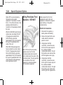
Keys and Locks
Specific Cylinder Unit for
Single Key - Random
Code System
If the vehicles are equipped with
one of these options, the entire fleet
of vehicle locks can be operated
with one key.
.
.
SEO 6E2-Specific Fleet
Key Code
SEO 6E8-Specific Fleet
Key Code
The vehicle will be equipped with a
standard production random key
code if one of the optional fleet
codes was not ordered.
For specific key code information,
contact your dealer.
The vehicle will be equipped with a
key cylinder in the ignition lock, the
driver door, and trunk lid. Remote
keyless entry (RKE) is a standard
feature and operates all doors and
the trunk lid. Six additional RKE
2-1
transmitters may have been ordered
with your vehicle. See your dealer
for additional information regarding
availability of more RKE units for the
vehicle.
The RKE transmitter for the police
vehicle has the vehicle locator/panic
alarm button disabled. The horn will
not sound and the exterior lights will
not flash when the button is
pressed.
Remote Keyless Entry
Transmitter Programming –
SEO AMF
Do not operate or program the
transmitters in the vicinity of other
vehicles that are in the keyless
entry program mode. This prevents
the programming of the transmitters
to the incorrect vehicle.
Up to eight transmitters may be
programmed to the RKE on police
package equipped vehicles.
Chevrolet Impala Police Package - 2013 - CRC - 4/10/12
2-2
Keys, Doors, and Windows
Verify that the proper transmitters
are learned to the vehicle. Do not
learn a transmitter with a remote
start button to a vehicle that does
not have remote start.
For the proper procedure to be used
for learning transmitters, see Driver
Information Center (DIC) on
page 5‑4.
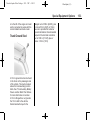
Trunk Lid Keylock Cylinder
The vehicle has a keylock cylinder
in the trunk lid.
If the vehicle is equipped with the
theft-deterrent system (Option UA6),
an audible alarm will occur when the
key is used to open the trunk
instead of the remote keyless entry
(key fob). See your dealer to disable
the audible alarm.
Black plate (2,1)
Chevrolet Impala Police Package - 2013 - CRC - 4/10/12
Black plate (1,1)
Seats and Restraints
Seats and
Restraints
Airbag System
Questions and Answers About
Airbags and Specialty Law
Enforcement Vehicles . . . . . . . 3-1
Notices for Customer Installed
Equipment . . . . . . . . . . . . . . . . . . . 3-3
Airbag Deployment
Diagrams . . . . . . . . . . . . . . . . . . . . 3-4
Airbag System
Questions and Answers
About Airbags and
Specialty Law
Enforcement Vehicles
Q: Can equipment such as radar
devices, video cameras, and
radio trees be mounted in a
specialty vehicle equipped
with a right front passenger
frontal airbag?
A: Yes, but care must be taken to
properly mount the equipment
outside of the airbag
“deployment zone.”
Q: What is the airbag
“deployment zone”?
A: The term “deployment zone”
describes the space an airbag
takes up when fully inflated.
Airbags need room to work
properly, and anything in the
“deployment zone” — such as
3-1
improperly mounted equipment
— can greatly affect the
performance of the airbag.
{ WARNING
Airbags inflate with great force,
faster than the blink of an eye. No
objects, such as shotguns, should
be placed over or near the airbag
covers. Equipment mounted too
close to an inflating airbag could
break and become a dangerous
projectile in a crash, causing
injury to the vehicle's occupants.
Also, an object too close to an
inflating airbag could prevent the
airbag from operating properly.
If this ever happens, the airbag
would not be able to protect
occupants the way it was
designed to. To help prevent
injury and to allow the airbag to
perform as it was designed, do
not mount equipment inside the
airbag deployment zone.
Chevrolet Impala Police Package - 2013 - CRC - 4/10/12
3-2
Black plate (2,1)
Seats and Restraints
Q: How can I identify the airbag
“deployment zone” in my
vehicle?
A: See Airbag Deployment
Diagrams on page 3‑4 for more
information. The diagrams
provide the approximate
dimensions of the “deployment
zones” for your specialty vehicle.
Before doing any service work,
including the installation of any
equipment, consult the
appropriate service manual.
Q: Is it possible to shield
equipment so it does not
interfere with airbag
deployment?
A: While shielding may protect
certain equipment from being
damaged or dislodged, it may
also negatively affect how an
airbag inflates. Therefore, we
cannot recommend the
placement of any equipment in
the deployment zone, even
when shielding.
Q: Can the installation of push
bumpers on the front end of
the vehicle affect the
deployment of the airbag?
A: General Motors is not aware of
adverse effects during crash
events from the many push
bumpers that have been
installed on GM police vehicles.
Because there are many styles
of push bumpers available with
varying crash characteristics,
installation of push bumpers may
or may not affect deployment
timing of the airbags. Push
bumpers should be mounted to
avoid modifying the vehicle
structure and interfering with the
front airbag sensors mounted on
the upper radiator support cross
member. Two front impact
sensors are installed in GM
vehicles. Do not relocate of
disconnect the front sensors.
The location and orientation of
the front sensors are critical for
correct operation of the airbag
system. Avoid mounting
components on or near the
sensors. Push bumper styles
with vertical pushing members
that are in fore-aft alignment with
the front airbag sensors are not
recommended.
Q: Is there anything I might add
to the front or sides of the
vehicle that could keep the
airbags from working
properly?
A: Yes. If you add things that
change your vehicle's frame,
bumper system, height, front end
or side sheet metal, they may
keep the airbag system from
working properly. Also, the
airbag system may not work
properly if you relocate any of
the airbag sensors. If you have
any questions about this, you
should contact Customer
Assistance before you modify
your vehicle. The phone
numbers and addresses for
Customer Assistance are in
Step Two of the Customer
Satisfaction Procedures in the
Chevrolet Impala Police Package - 2013 - CRC - 4/10/12
Black plate (3,1)
Seats and Restraints
owner manual. See “Customer
Satisfaction Procedure” in the
owner manual.
The service manual has information
about the location of the airbag
sensors, sensing and diagnostic
module, and airbag wiring. See
“Service Publications Ordering
Information” in the owner manual.
Notices for Customer
Installed Equipment
Notice: In order not to restrict
upward movement of the driver's
side instrument panel top pad
when the airbag deploys,
equipment should be securely
mounted only to the top pad.
Notice: Do not place equipment
on the passenger's side of the
instrument panel top pad because
the edge of it rises when the
airbag deploys.
Notice: GM-approved service
procedures must be followed to
remove and reinstall the
instrument panel to the pad in
order to ensure proper airbag
deployment.
Notice: Do not mount equipment
on the passenger side of the
instrument panel top pad
deployment zone. Equipment
should not be mounted on or
around the passenger airbag
opening because of a deploying
airbag. To allow the airbag to
perform as it was designed, do
not mount equipment inside the
airbag deployment zone.
Notice: Equipment mounted to
the instrument panel top pad
must not exceed 8.0 lb (3.6 kg).
Notice: Passenger airbag
contacts inside rearview mirror at
the beginning of deployment.
Read the following notices before
installing equipment on the specialty
vehicle.
3-3
Video cameras and other small
equipment should be securely
mounted outside the airbag zone.
Notice: The police vehicle has
roof-rail airbags. Do not mount a
security barrier such that the
ends of the barrier or brackets
are within the roof-rail
deployment zones.
Notice: Avoid installing wiring for
roof-rail emergency lighting or
radio antennas that may restrict
the proper deployment of the
roof-rail airbags.
Notice: The police vehicle has
seat‐mounted side impact airbags
for the driver and passenger front
seat positions. Restricting the
cover from opening prevents
proper deployment of the seat‐
mounted side impact airbag. Do
not cover or restrict the seat‐
mounted side impact airbag cover
located on the outboard side of
the seatback.
Chevrolet Impala Police Package - 2013 - CRC - 4/10/12
3-4
Black plate (4,1)
Seats and Restraints
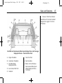
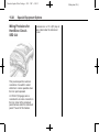
Airbag Deployment Diagrams
A. Shift Selector Arc
B. Driver Side Door
C. Front of Steering Wheel (In
Maximum Downward Position)
D. Driver Airbag Deployment Zone
E. Driver Centerline (Also See
Side View)
F.
Vehicle Centerline
G. Inside Rearview Mirror
H. Passenger Centerline (Also See
Side View)
I.
Passenger Airbag
Deployment Zone
J.
Approximate Maximum
Dimension of Inflated Airbag
K. Passenger Side Door
L.
Rear Edge of Instrument Panel
Top Pad
M. Zone from Instrument Panel Top
to Windshield
Instrument Panel Top View – Approximate Airbag Deployment Zone
See Notices for Customer Installed
Equipment on page 3‑3 for more
information.
Chevrolet Impala Police Package - 2013 - CRC - 4/10/12
Black plate (5,1)
Seats and Restraints
3-5
See Notices for Customer Installed
Equipment on page 3‑3 for more
information.
Side View of Driver Side Airbag
Deployment Zone – Centerline
of Driver
A. Driver Airbag Deployment Zone
B. Top of Windshield
Side View of Passenger Side
Airbag Deployment Zone –
Centerline of Passenger
A. Passenger Airbag
Deployment Zone
C. Front of Steering Wheel
(Maximum Downward Position)
B. Top of Windshield
D. Top of Instrument Panel
D. Top of Instrument Panel
See Notices for Customer Installed
Equipment on page 3‑3 for more
information.
E. Passenger Seat in Foremost
Position
C. Inside Rearview Mirror
F.
Passenger Seat in Rearmost
Position
Chevrolet Impala Police Package - 2013 - CRC - 4/10/12
3-6
Black plate (6,1)
Seats and Restraints
H. Groove in Front Door Armrest
I.
Pillar Trim
J.
Approximate Shape of
Deployed Airbag at
Maximum Size
K. Bottom of Deployment Zone
L.
Bottom of Door Windows
See Notices for Customer Installed
Equipment on page 3‑3 for more
information.
Roof Rail and Seat-mounted Side Impact Airbags Maximum Deployment
Zone – Driver Side Shown, Passenger Side Similar
A. Top of Deployment Zone –
Along Roof Rail at Edge of
Headliner
D. Front of Deployment Zone – At
Front of Outside Mirror Patch
B. Airbag Inflator Location on Sail
Panel
F.
C. Back of Deployment Zone – At
Rear of Quarter Window
G. Door Handle Front End
E. Forward Airbag Tether Line
Seat-mounted Side Impact
Airbag Deployment Zone
Chevrolet Impala Police Package - 2013 - CRC - 4/10/12
Black plate (7,1)
Seats and Restraints
J.
3-7
Groove in Front Door Armrest
See Notices for Customer Installed
Equipment on page 3‑3 for more
information.
Roof Rail and Seat-mounted Side Impact Airbags Driver and Passenger
Deployment Zones – View from Rear Seat
A. Edge of Headliner
F.
B. Underside of Headliner
G. Seat Centerline
C. Roof Rail Airbag
Deployment Zone
H. Bottom of Door Windows
D. Inner Center Pillar Trim
E. Headrest
I.
Inner Door Pad
Seat-mounted Side Impact
Airbag Deployment Zone –
Front Seat
Chevrolet Impala Police Package - 2013 - CRC - 4/10/12
3-8
Black plate (8,1)
Seats and Restraints
2 NOTES
Chevrolet Impala Police Package - 2013 - CRC - 4/10/12
Black plate (1,1)
Instruments and Controls
Instruments and
Controls
Warning Lights, Gauges, and
Indicators
Instrument Cluster . . . . . . . . . . . . 5-2
Electronic Stability Control
(ESC) Off Light . . . . . . . . . . . . . . 5-3
Information Displays
Driver Information
Center (DIC) . . . . . . . . . . . . . . . . . 5-4
Vehicle Messages
Ride Control System
Messages . . . . . . . . . . . . . . . . . . . 5-5
Warning Lights,
Gauges, and
Indicators
5-1
Chevrolet Impala Police Package - 2013 - CRC - 4/10/12
5-2
Instruments and Controls
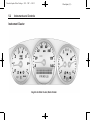
Instrument Cluster
English Certified Cluster, Metric Similar
Black plate (2,1)
Chevrolet Impala Police Package - 2013 - CRC - 4/10/12
Black plate (3,1)
Instruments and Controls
The words CERTIFIED
SPEEDOMETER will flash in the
Driver Information Center (DIC)
display for approximately
two seconds when the engine is
started. The DIC can be set to
display digital vehicle speed while
the vehicle is being driven. See
Driver Information Center (DIC) on
page 5‑4.
Electronic Stability
Control (ESC) Off Light
Press and briefly hold the ESC OFF
button to turn off the ESC system;
the ESC OFF light comes on and a
message appears in the Driver
Information Center (DIC).
See Ride Control System Messages
on page 5‑5 for more information.
If the TCS/ESC system is off, the
system does not assist in controlling
the vehicle. Turn on the TCS/ESC
system and the indicator light
turns off.
See Traction Control System (TCS)
on page 9‑2, and Electronic Stability
Control (ESC) on page 9‑3 for more
information.
Performance Mode
This light comes on briefly while
starting the engine.
If it does not, have the vehicle
serviced by your dealer. If the
system is working normally, the
indicator light then goes off.
5-3
When the ESC OFF button is
pressed, th ESC OFF light comes
on and PERFORMANCE MODE
displays in the DIC.
The traction control system is still
active, but limited to driveline
protection only. ESC is also active,
but is limited to high-speed pursuit
purposes.
See the owner manual for more
information.
Chevrolet Impala Police Package - 2013 - CRC - 4/10/12
5-4
Black plate (4,1)
Instruments and Controls
Information Displays
Driver Information
Center (DIC)
Trip/Fuel Menu Items
3 (Trip/Fuel):
Press this button
to scroll through the following menu
items:
Digital Speedometer
The speedometer shows how fast
the vehicle is moving in either
kilometers per hour (km/h) or miles
per hour (mph). The speedometer
cannot be reset.
Vehicle Information Menu
Items
T (Vehicle Information):
Press
this button to scroll through the
following menu items:
Relearn Remote Key
To access this display, the vehicle
must be in P (Park). This display
allows you to match the Remote
Keyless Entry (RKE) transmitter to
the vehicle. This procedure will
erase all previously learned
transmitters. Therefore, they must
be relearned as additional
transmitters.
To match an RKE transmitter:
1. Press T until PRESS TO
RELEARN REMOTE KEY
displays.
2. Press V. REMOTE KEY
LEARNING ACTIVE is
displayed.
3. Press and hold the lock and
unlock buttons on the first
transmitter at the same time for
about 15 seconds.
A chime will sound indicating
that the transmitter is matched.
4. To match additional transmitters
at this time, repeat Step 3.
Each vehicle can have a
maximum of eight transmitters
matched to it.
5. To exit the programming mode,
you must cycle the key to
LOCK/OFF.
Chevrolet Impala Police Package - 2013 - CRC - 4/10/12
Black plate (5,1)
Instruments and Controls
Vehicle Messages
Ride Control System
Messages
PERFORMANCE MODE
This message displays when the
ESC OFF button is pressed once.
See Electronic Stability Control
(ESC) on page 9‑3 for more
information.
5-5
Chevrolet Impala Police Package - 2013 - CRC - 4/10/12
5-6
Black plate (6,1)
Instruments and Controls
2 NOTES
Chevrolet Impala Police Package - 2013 - CRC - 4/10/12
Black plate (1,1)
Lighting
Lighting
Exterior Lighting
Exterior Lamp Controls . . . . . . . . 6-1
Exterior Lighting
Exterior Lamp Controls
Police Package and Special
Service Package
The following exterior lighting
features apply to vehicles first sold
in the United States.
The vehicle has Daytime Running
Lamps (DRL) and an Automatic
Headlamp System (AHS). The DRL
and AHS can be turned to OFF with
the headlamp switch when the
transmission is in P (Park) and the
engine is at idle. If the engine is not
turned off, the DRL and AHS will
remain OFF when the transmission
is placed in gear. The vehicle may
be driven with the lamps off for one
ignition cycle.
The vehicle may have been built
with SEO 9G8, DRL AND AHS
DISABLE. This feature turns off
DRL and AHS and requires manual
6-1
control of the exterior lighting. See
your dealer to restore the DRL and
AHS to normal operation.
For vehicles first sold in Canada,
the DRL and AHS can be turned off
if the transmission is in P (Park).
See the owner manual.
Special Features
Police Package and Special
Service Package
The following standard features are
disabled in the Police Package and
Special Service Package.
.
Entry Lighting and Exit Lighting
.
Remote Keyless Entry
Feedback: Horn Beep and
Lamps Flash
.
Automatic Door Locking and
Unlocking
Chevrolet Impala Police Package - 2013 - CRC - 4/10/12
6-2
Black plate (2,1)
Lighting
2 NOTES
Chevrolet Impala Police Package - 2013 - CRC - 4/10/12
Black plate (1,1)
Driving and Operating
Driving and
Operating
Driving Information
Vehicle Load Limits . . . . . . . . . . . 9-1
Starting and Operating
Fast Idle System . . . . . . . . . . . . . . 9-1
Ride Control Systems
Traction Control
System (TCS) . . . . . . . . . . . . . . . 9-2
Electronic Stability
Control (ESC) . . . . . . . . . . . . . . . 9-3
Towing
Trailer Towing . . . . . . . . . . . . . . . . . 9-5
Driving Information
Vehicle Load Limits
Impala police vehicles may have a
full-size spare tire. If the full-size
spare tire is stored in the trunk of
the vehicle, do not carry more than
64 kg (141 lbs) in the trunk. See
“Vehicle Load Limits” in the owner
manual.
9-1
Starting and
Operating
Fast Idle System
While parked with the engine idling
for an extended period, turn off the
following factory equipment if
emergency lighting and
communication equipment are
operating:
.
Air Conditioner
.
Fan
.
Rear Window Defogger
.
Factory Audio System
When the automatic transmission is
in P (Park), the driver's foot is off the
brake, and the emergency
equipment is turned on, the engine
rpm may increase to 1,200 rpm to
keep the electrical power of the
vehicle at a steady rate. Even with
the extra power boost, the vehicle
may stall after long periods of time
with a heavy electrical load.
Chevrolet Impala Police Package - 2013 - CRC - 4/10/12
9-2
Black plate (2,1)
Driving and Operating
See “Running the Vehicle While
Parked” in the owner manual.
Ride Control Systems
Traction Control
System (TCS)
The vehicle may have a Traction
Control System (TCS) that limits
wheel spin. This is especially useful
in slippery road conditions. The
system operates only if it senses
that one or both of the front wheels
are spinning or beginning to lose
traction. When this happens, the
system reduces engine power and
may also upshift the transmission
and apply the front brakes to limit
wheel spin.
This light will flash when the TCS is
limiting wheel spin.
The system may be heard or felt
while it is working, but this is
normal.
The TCS is automatically enabled
whenever the vehicle is started. The
system can be turned off, but it will
no longer assist in controlling the
vehicle.
If cruise control is being used when
TCS begins to limit wheel spin, the
cruise control will automatically
disengage. Cruise control may be
reengaged when road conditions
allow. See “Cruise Control” in owner
manual,
The TCS operates in all
transmission shift lever positions.
But the system can upshift the
transmission only as high as the
shift lever position chosen, so use
the lower gears only when
necessary. See “Automatic
Transmission” in the owner manual.
Chevrolet Impala Police Package - 2013 - CRC - 4/10/12
Black plate (3,1)
Driving and Operating
9-3
Electronic Stability
Control (ESC)
When the system is on, this warning
light comes on and stays on if there
is a problem.
To disable both traction control and
ESC, press and hold the ESC OFF
button briefly.
A SERVICE TRACTION CONTROL
message also appears on the DIC.
When this warning light is on, the
system will not limit wheel spin.
Adjust your driving accordingly. See
“Messages” under “Ride Control
System” in the owner manual.
When the ESC OFF button is
pressed, the ESC Off light comes
on and PERFORMANCE MODE
displays in the DIC. The TCS is still
active, but limited to driveline
protection only. ESC is also active,
but is limited to high speed pursuit
purposes.
To limit wheel spin, especially in
slippery road conditions, TCS
should always be left on. But the
system can be turned off if needed.
Turn the system off if the vehicle
gets stuck in sand, mud, or snow
and rocking the vehicle is required.
See “If the Vehicle Is Stuck” under
“Driving” in the owner manual.
Press the ESC OFF button again to
turn the system back on. The
TRACTION CONTROL ON
message will appear in the DIC.
Adding non-dealer accessories can
affect the vehicle performance. See
“Accessories and Modifications” in
the owner manual.
Your vehicle may have an Electronic
Stability Control (ESC) system
which combines antilock brake,
traction, and stability control
systems and helps the driver
maintain directional control of the
vehicle in most driving conditions.
When you first start your vehicle
and begin to drive away, the system
performs several diagnostic checks
to ensure there are no problems.
You may hear or feel the system
working. This is normal and does
not mean there is a problem with
your vehicle. The system should
initialize before the vehicle reaches
32 km/h (20 mph).
If the system fails to turn on or
activate due to a fault, the ESC/TCS
light will be on solid, and the
SERVICE STABILITRAK message
will be displayed. If the system fails
to turn on or activate due to it not
initializing, the DIC will display
Chevrolet Impala Police Package - 2013 - CRC - 4/10/12
9-4
Black plate (4,1)
Driving and Operating
STABILITRAK INITIALIZING. See
“Messages” under “Ride Control
System” in the owner manual.
This light will flash on the instrument
panel cluster when the ESC system
is both on and activated.
You may also feel or hear the
system working; this is normal.
When the light is on solid and the
SERVICE STABILITRAK message
is displayed, the system will not
assist the driver in maintaining
directional control of the vehicle.
Adjust your driving accordingly. See
“Messages” under “Ride Control
System” in the owner manual.
The Electronic Stability
Control (ESC) system is
automatically enabled whenever you
start your vehicle. To assist the
driver with vehicle directional
control, especially in slippery road
conditions, you should always leave
the system on. But, you can turn
ESC off if you ever need to.
If the vehicle is in cruise control
when the system begins to assist
the driver maintain directional
control of the vehicle, the ESC/TCS
light will flash and the cruise control
will automatically disengage. When
road conditions allow you to use
cruise again, you may re-engage
the cruise control. See “Cruise
Control” in the owner manual.
The ESC OFF button is located on
the instrument panel.
To disable both traction control and
ESC, press and hold the button
briefly.
When the ESC OFF button is
pressed, the ESC Off light comes
on and PERFORMANCE MODE
displays in the DIC. The TCS is still
active, but limited to driveline
protection only. ESC is also active,
but is limited to high speed pursuit
purposes.
It is recommended to leave the
system on for normal driving
conditions, but it may be necessary
to turn the system off if your vehicle
is stuck in sand, mud, ice, or snow,
and you want to “rock” your vehicle
to attempt to free it. It may also be
necessary to turn off the system
when driving in extreme off-road
conditions where high wheel spin is
required. See “If the Vehicle Is
Stuck” under “Driving” in the owner
manual.
Chevrolet Impala Police Package - 2013 - CRC - 4/10/12
Black plate (5,1)
Driving and Operating
ESC may also turn off automatically
if it determines that a problem exists
with the system. The SERVICE
STABILITRAK message and the
ESC/TCS light will be on solid to
warn the driver that ESC is disabled
and requires service. If the problem
does not clear after restarting the
vehicle, you should see your dealer
for service. See “Messages” under
“Ride Control System” in the owner
manual.
Adding non-dealer accessories can
affect your vehicle performance.
See “Accessories and Modifications”
in the owner manual.
Towing
Trailer Towing
Impala police vehicles are not
intended to tow a trailer.
9-5
Chevrolet Impala Police Package - 2013 - CRC - 4/10/12
9-6
Black plate (6,1)
Driving and Operating
2 NOTES
Chevrolet Impala Police Package - 2013 - CRC - 4/10/12
Black plate (1,1)
Vehicle Care
Vehicle Care
Vehicle Checks
Brakes . . . . . . . . . . . . . . . . . . . . . . . 10-1
Wheels and Tires
Tire Pressure Monitor
System . . . . . . . . . . . . . . . . . . . . . 10-1
Compact Spare Tire . . . . . . . . . 10-2
Full-Size Spare Tire
(SEO N81) . . . . . . . . . . . . . . . . . 10-3
Vehicle Checks
Wheels and Tires
Brakes
Tire Pressure Monitor
System
All Impala police vehicles have the
Antilock Brake System (ABS). Many
of the components of the brake
system used on the Impala police
vehicle are unique to the vehicle.
Before doing any service work,
consult the appropriate service
manual.
See “Brakes” in the owner manual
for additional information on the
brake system.
10-1
The Impala full-size spare includes
a sensor for the Tire Pressure
Monitor System (TPMS). The
compact spare tire/wheel, which is
standard with the Impala Police
Package, does not include a TPMS
sensor. The TPMS will not monitor
or display the spare tire air pressure
until the tire/wheel is installed at one
of the four tire/wheel positions on
the vehicle.
Once installed, the spare tire sensor
code must be matched to the new
position on the vehicle. See “Tire
Pressure Monitor Operation” in the
owner manual for information about
matching the spare tire to
the TPMS.
Chevrolet Impala Police Package - 2013 - CRC - 4/10/12
10-2
Black plate (2,1)
Vehicle Care
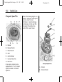
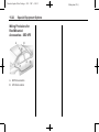
Compact Spare Tire
Refer to the following diagram as a
guide for storing the compact spare
tire in the trunk. For more
information on spare tire storage
and changing a flat tire, see “Tire
Changing” in the Vehicle Care
section of the owner manual.
A. Retainer
B. Retainer Bracket
C. Wheel Wrench
D. Jack
E. Jack Container
F.
Compact Spare Tire
G. Bolt Screw
Impala police vehicles may be
equipped with a 17–inch compact
spare tire instead of a full-size
spare tire.
Compact Spare Tire
A. Retainer
B. Retainer Bracket
Chevrolet Impala Police Package - 2013 - CRC - 4/10/12
Black plate (3,1)
Vehicle Care
C. Wheel Wrench
D. Jack
E. Jack Container
F.
Compact Spare Tire
G. Bolt Screw
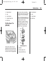
Full-Size Spare Tire
(SEO N81)
Impala police vehicles may be
equipped with a full-size spare tire.
When the full-size spare tire option
is ordered, the tire is equipped with
a vinyl cover and a surrounding
trunk mat. See Vehicle Load Limits
on page 9‑1 for more information.
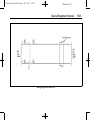
Refer to the following diagram as a
guide for storing the full-size spare
tire in the trunk. For more
information on spare tire storage
and changing a flat tire, see “Tire
Changing” in the Vehicle Care
section of your owner manual.
Full-Size Spare Tire
A. Retainer
B. Full-Size Spare Tire
C. Extension Bolt Screw
D. Wheel Wrench
E. Jack
F.
Foam Holder
G. Bolt Screw
10-3
Chevrolet Impala Police Package - 2013 - CRC - 4/10/12
10-4
Black plate (4,1)
Vehicle Care
2 NOTES
Chevrolet Impala Police Package - 2013 - CRC - 4/10/12
Black plate (1,1)
Service and Maintenance
Service and
Maintenance
Recommended Fluids,
Lubricants, and Parts
Maintenance Replacement
Parts . . . . . . . . . . . . . . . . . . . . . . . 11-2
11-1
Chevrolet Impala Police Package - 2013 - CRC - 4/10/12
11-2
Black plate (2,1)
Service and Maintenance
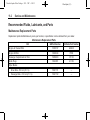
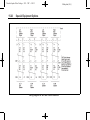
Recommended Fluids, Lubricants, and Parts
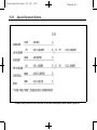
Maintenance Replacement Parts
Replacement parts identified below by name, part number, or specification can be obtained from your dealer.
Maintenance Replacement Parts
Part
GM Part Number
ACDelco Part Number
Engine Air Cleaner/Filter
10350737
A2962C
Engine Oil Filter
12600224
PF48
Passenger Compartment Air Filter
15284938
CF132
Spark Plugs
12622561
41‐109
Driver Side ‐ 55.0 cm (21.7 in)
15941731
—
Passenger Side ‐ 55.0 cm (21.7 in)
15941732
—
Wiper Blades
Chevrolet Impala Police Package - 2013 - CRC - 4/10/12
Black plate (1,1)
Special Equipment Options
Special Equipment
Options
SEO Standard Options
SEO Standard Options Police Package and Special
Service Package . . . . . . . . . . . 15-2
Power Steering/Engine Oil
Cooling System . . . . . . . . . . . . 15-2
Trunk Ground Stud . . . . . . . . . . 15-3
Wiring Provisions for 12-Volt
Battery Power Supply . . . . . . 15-4
Auxiliary Battery Power
Junction Blocks . . . . . . . . . . . . 15-8
Heavy Duty Cooling
System . . . . . . . . . . . . . . . . . . . 15-10
Radios . . . . . . . . . . . . . . . . . . . . . 15-10
Seats . . . . . . . . . . . . . . . . . . . . . . . 15-10
Trunk Mat . . . . . . . . . . . . . . . . . . 15-10
SEO Available Options
SEO Available Options Police Package and Special
Service Package . . . . . . . . . . 15-11
Auxiliary Dome Lamp SEO 6C7 . . . . . . . . . . . . . . . . . . 15-11
Dome Lamp Inoperative
Function - SEO 7Y6 . . . . . . . 15-12
Inoperative Rear Door
Handles - SEO 6B2 . . . . . . . 15-12
Exterior Lamp Emergency
Flashing System SEO 6J7 . . . . . . . . . . . . . . . . . . 15-12
Heavy Duty Floor Covering SEO 6A3 . . . . . . . . . . . . . . . . . . 15-15
Ignition Control Trunk
Release - SEO A98 . . . . . . . 15-15
Rear Panel Lamps SEO 6J6 . . . . . . . . . . . . . . . . . . 15-15
Rear Windows Inoperative SEO 6N5 . . . . . . . . . . . . . . . . . 15-15
Inoperative Rear Door Locks
- SEO 6N6 . . . . . . . . . . . . . . . . 15-15
15-1
Spotlamp - SEO 7X6 . . . . . . . 15-16
Spotlamps - SEO 7X7 . . . . . . 15-16
Wiring Provisions for Vehicle
Grille Lamps and Speaker/
Siren - SEO 6J3 . . . . . . . . . . 15-17
Spotlamp Provisions SEO 7X8 . . . . . . . . . . . . . . . . . . 15-19
Spotlamp Provisions SEO 7X9 . . . . . . . . . . . . . . . . . . 15-19
Trunk Lid Warning Lamps SEO T53 . . . . . . . . . . . . . . . . . . 15-19
Wiring Provisions for Horn/
Siren Circuit - SEO 6J4 . . . 15-20
Wiring Provisions for
Roof-Mounted Accessories
- SEO 6F5 . . . . . . . . . . . . . . . . 15-22
Wiring Provisions Front
Speakers - SEO WX7 . . . . . 15-24
Wiring Provisions Rear
Coaxial Cable SEO 6C8 . . . . . . . . . . . . . . . . . 15-27
Chevrolet Impala Police Package - 2013 - CRC - 4/10/12
15-2
Special Equipment Options
SEO Standard
Options
SEO Standard Options Police Package and
Special Service Package
.
See that all added wiring is
of the same or larger gauge
than the wire it is being
attached to for proper fuse
protection.
.
Be sure that all holes drilled
in the body are properly
sealed and corrosion
protected. See that the
vehicle's wiring harnesses,
piping, and other
components have not been
displaced or damaged during
customer installations of
equipment and wiring.
.
Do not route wiring or
equipment which could
interfere with roof‐mounted
side impact airbags.
Notice: GM cannot be
responsible for any changes
made to the vehicle. Have all
electrical and body modifications
performed by experienced
technicians.
.
.
.
Black plate (2,1)
Be sure that any modified or
added wiring will work
properly with your vehicle's
wiring system.
See that all wiring is properly
protected by fuses, and not
causing an overload to
connectors and components.
Do not route wiring in areas
of the vehicle where
temperatures can be high or
where wiring may be cut,
pinched, or rubbed.
Notice: Overloading the vehicle's
electrical system may damage
your vehicle's accessories. Do
not overload the vehicle's system
by having unnecessary
accessories on at the same time.
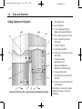
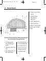
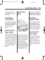
Power Steering/Engine
Oil Cooling System
A. Engine Oil Cooler
B. Transmission Fluid Cooler
C. Power Steering Cooler
Your Impala police vehicle is
equipped with auxiliary fin-type
air-to-oil coolers mounted in front of
the engine coolant radiator.
The auxiliary coolers are mounted
separately, with the power steering
cooler just below the engine oil
cooler. The transmission fluid cooler
Chevrolet Impala Police Package - 2013 - CRC - 4/10/12
Black plate (3,1)
Special Equipment Options
is to the left of the engine oil cooler
and is connected in series with the
coolant radiator end-tank cooler.
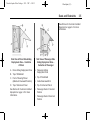
Trunk Ground Stud
A 10 mm ground stud can be found
in the trunk on the passenger side
of the vehicle. The stud is located
above the trunk auxiliary junction
block. See “Trunk Auxiliary Battery
Power Junction Block” that follows
for more information on location.
A 10 mm flanged hex nut grounds
the 10 mm bolt to the vehicle.
Recommended torque for the
flanged nut is 35 N·m (26 lb ft), plus
or minus 5 N·m (4 lb ft). A 10 mm
hex nut is provided for customer
ground termination. Recommended
torque for the terminal connection
nut is 10 N·m (7.3 lb ft), plus or
minus 1.3 N·m (1 lb ft).
15-3
Chevrolet Impala Police Package - 2013 - CRC - 4/10/12
15-4
Special Equipment Options
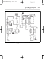
Wiring Provisions for 12-Volt Battery Power Supply
Black plate (4,1)
Chevrolet Impala Police Package - 2013 - CRC - 4/10/12
Black plate (5,1)
Special Equipment Options
15-5
Chevrolet Impala Police Package - 2013 - CRC - 4/10/12
15-6
Black plate (6,1)
Special Equipment Options
Battery power is supplied through
two fusible links, one 50 amp and
one 65 amp, to three circuit
breakers and two control relays
located in the relay center above the
accelerator pedal. For location
information, see “Servicing Relays
and Circuit Breakers” in the Index.
A 50 amp circuit breaker feeds
power directly from the 50 amp
fusible link through a 5.0 mm²
(10 gauge) blunt cut wire. Two
30 amp circuit breakers supply
power from the 65 amp fusible link
through the contacts of the control
relays to 3.0 mm² (12 gauge) blunt
cut wires. The blunt cut leads are
part of a 1.5 m (5 ft) loop of wire
coiled under the instrument panel in
the front passenger side footwell.
Each relay is operated by an
0.8 mm² (18 gauge) blunt cut, light
or dark blue control lead included in
the 1.5 m (5 ft) coil under the
instrument panel. An 8.0 mm²
(8 gauge) ground lead is also
provided in the 1.5 m (5 ft) coil. The
total current available through the
12-volt power supply is 110 amps
(1320 watts).
switched power when the
transaxle is not in PARK (P) and
the engine is running. The
electrical load attached to the
park circuit must not exceed
0.5 amps and is meant to drive
one relay coil.
Blunt cut ignition controlled power
and signal circuits are also included
in the following 1.5 m (5 ft) right
foot loop:
.
A yellow, 0.5 mm² (20 gauge)
10 amp fused circuit, Hot in
ACC/ACCESSORY, ON/RUN or
RAP (Retained Accessory
Power). The fuse for this circuit
is labeled “RAP” and is located
in the fuse block in the front
passenger side instrument
panel.
.
A pink, 0.5 mm² (20 gauge)
10 amp fused circuit, Hot in
START and ON/RUN. The fuse
for this circuit is labeled “PWR
DROP/CRANK” and is located in
the underhood fuse block in the
engine compartment.
.
A yellow/black, 0.5 mm²
(20 gauge) transaxle park signal
from the Body Control Module
(BCM). The circuit provides a
.
A brown, 0.35 mm² (22 gauge)
vehicle speed signal (4,000
pulses/mile) from the ABS
module. Connect only high
impedance load.
Servicing Relays and Circuit
Breakers
The following information shows you
where the relays and circuit
breakers are located in the Fuse
Block‐SEO.
Chevrolet Impala Police Package - 2013 - CRC - 4/10/12
Black plate (7,1)
Special Equipment Options
A. Instrument Panel Carrier
B. Relay Center for Circuit
Breakers and Control Relay
C. Instrument Panel Harness
Branch
Enlarged View of the SEO Fuse
Block
A. Relays and Circuit Breakers
B. Front of the Vehicle
C. Floor of the Vehicle
15-7
Chevrolet Impala Police Package - 2013 - CRC - 4/10/12
15-8
Black plate (8,1)
Special Equipment Options
Auxiliary Battery Power
Junction Blocks
3. Reconnect the negative (−)
battery cable to the battery.
4. Set the time on the clock and
radio pushbuttons as needed.
See “Audio System” in the
owner manual.
The auxiliary battery power junction
block is mounted in the trunk of your
Impala police vehicle. It is located
on the passenger side support strut
behind the rear wheel housing.
This junction block is split to provide
two circuits and can be used to
connect customer-furnished
equipment directly to the battery
through 8.0 mm² ( 8 gauge) body
wiring and fusible links. A maximum
of 100 amps (1200 watts) can be
connected. Torque the connections
to the studs to 15 N·m (11 lb ft). It is
fed by two fusible links of
50 amps each.
To connect the customer-furnished
equipment at the junction block, use
the following steps:
1. Disconnect the negative (−)
battery cable.
2. Connect the customer-furnished
equipment positive leads to the
junction block terminals and
tighten to 15 N·m (11 lb ft).
The ignition must be turned off
and the vehicle vacated prior to
connecting the negative (−)
battery cable to the battery.
Chevrolet Impala Police Package - 2013 - CRC - 4/10/12
Black plate (9,1)
Special Equipment Options
Wiring Diagram for Trunk Auxiliary Battery Power Junction Block
15-9
Chevrolet Impala Police Package - 2013 - CRC - 4/10/12
15-10
Black plate (10,1)
Special Equipment Options
Heavy Duty Cooling
System
A high capacity radiator and fan
replace the standard cooling
system. Refer to the owner manual
for more information on the cooling
system.
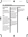
Radios
Chime Level Adjustment
Impala police vehicles are equipped
with a radio that provides an AM-FM
stereo with a CD player. The radio
produces the required warning
chimes for the vehicle. The volume
level of the chimes can be adjusted
to be louder, but cannot be
turned off.
The sound for the warning chimes is
directed to the left front door
speaker. When SEO WX7 (wiring
provisions for the front speakers) is
installed, the sound is directed to
the left rear speaker.
See “Climate Control Systems” and
“Audio System” in the owner manual
to adjust the chime volume or
contact your dealer for assistance.
Radio Suppression
Impala police vehicles are equipped
with spark plugs and spark plug
wires designed to reduce radio
interference noise levels which may
affect communication equipment,
including operating frequencies in
the 38 MHz to 58 MHz range.
Seats
Impala SEO 9C1 police vehicles are
equipped with high‐density foam
front seats that have security panels
in the seatbacks and a high‐density
foam rear seat cushion and
seatback.
Trunk Mat
A heavy duty vinyl mat covers the
trunk floor in vehicles equipped with
either a compact or full‐size
spare tire.
Chevrolet Impala Police Package - 2013 - CRC - 4/10/12
Black plate (11,1)
Special Equipment Options
SEO Available
Options
SEO Available Options Police Package and
Special Service Package
.
See that all added wiring is
of the same or larger gauge
than the wire it is being
attached to for proper fuse
protection.
.
Be sure that all holes drilled
in the body are properly
sealed and corrosion
protected. See that the
vehicle's wiring harnesses,
piping, and other
components have not been
displaced or damaged during
customer installations of
equipment and wiring.
.
Do not route wiring or
equipment which could
interfere with roof‐mounted
side impact airbags.
Notice: GM cannot be
responsible for any changes
made to the vehicle. Have all
electrical and body modifications
performed by experienced
technicians.
.
Be sure that any modified or
added wiring will work
properly with your vehicle's
wiring system.
.
See that all wiring is properly
protected by fuses, and not
causing an overload to
connectors and components.
.
Do not route wiring in areas
of the vehicle where
temperatures can be high or
where wiring may be cut,
pinched, or rubbed.
15-11
Auxiliary Dome Lamp SEO 6C7
The auxiliary dome lamp has red
LED/white incandescent lights and
is located on the headliner between
the driver and the front passenger
seating positions. The button for this
lamp is located at the rear base of
the lamp. The lamp is wired
independently. To operate the lamp,
press the button. To turn the lamp
off, press the button again.
Chevrolet Impala Police Package - 2013 - CRC - 4/10/12
15-12
Black plate (12,1)
Special Equipment Options
Dome Lamp Inoperative
Function - SEO 7Y6
Inoperative Rear Door
Handles - SEO 6B2
This feature makes the rear door
handles inoperative. When the
feature is enabled, the inside rear
door handles are disconnected and
the rear doors can only be opened
from the outside.
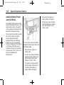
Exterior Lamp
Emergency Flashing
System - SEO 6J7
This feature makes the dome lamp
inoperative when a door is opened.
The dome and courtesy lamps can
only be controlled using the dome
lamp button on the overhead
console.
SEO 6J7 provides a high-beam
headlamps flashing module, rear
lamps flashing, and control wire for
a customer-furnished switch to turn
the module on or off. The flasher
control wire is coiled in the
passenger side footwell under the
instrument panel. This control lead
may be combined with the interior
wiring leads for SEO 6J3 when that
option is ordered with SEO 6J7.
The headlamps flashing module is
located at the inboard end of the
passenger side headlamps
assembly. The headlamps flashing
module is activated by the
application of 12 volts to a red/white
wire coiled in the passenger side
footwell. When activated, the driver
and passenger side high-beam
headlamps will flash alternately at
2.4 flashes per second.
During daylight conditions, the
Daytime Running Lamps (DRL) are
automatically turned off whenever
the headlamps flasher module is
activated. During nighttime
conditions, the low-beam
headlamps turn on automatically
while the high-beam headlamps
flash. Turning on the high-beam
headlamps manually with the turn
signal/multifunction lever will
override the flashing module and
the high-beam headlamps will
operate continuously.
A fuse labeled HDLP MDL protects
the flasher module circuit. This fuse
is located in the underhood fuse
block in the engine compartment on
Chevrolet Impala Police Package - 2013 - CRC - 4/10/12
Black plate (13,1)
Special Equipment Options
the passenger side of the vehicle.
See “Fuses and Circuit Breakers” in
the owner manual.
When the headlamps flashing
module is turned on, the module
sends a signal to the Body Control
Module (BCM). The BCM alternately
flashes the stop lamps and backup
lamps. Depressing the brake pedal
will override the stop lamp flashing
and placing the transaxle in reverse
will override the backup lamp
flashing.
When it is dark outside, the
taillamps will turn on automatically.
The Center High-Mounted Stoplamp
(CHMSL) will not flash and will
operate only when the regular brake
pedal is pressed.
15-13
Chevrolet Impala Police Package - 2013 - CRC - 4/10/12
15-14
Black plate (14,1)
Special Equipment Options
Forward Lamp Harness In-Line Connector for use with Headlamps Flasher Module, Option 6J7
Chevrolet Impala Police Package - 2013 - CRC - 4/10/12
Black plate (15,1)
Special Equipment Options
The connector is located on the
back of the passenger side of the
bumper beam.
Rear Panel Lamps SEO 6J6
15-15
loops allow customer installation of
an in-line switch in each lamp circuit
to disable the auxiliary lamp feature.
Heavy Duty Floor
Covering - SEO 6A3
Rear Windows
Inoperative - SEO 6N5
Impala police vehicles are equipped
with carpet and carpeted floor mats.
Optional heavy floor covering may
replace the carpeting and
floor mats.
This feature makes the rear window
switches inoperative. While the
feature is enabled, the rear window
switches are disconnected and the
rear windows can only be operated
from the driver's window switch.
Ignition Control Trunk
Release - SEO A98
Impala police vehicles are equipped
with an electric trunk release which
operates when the vehicle's ignition
is in LOCK/OFF. This feature can be
changed, however, to operate only
when the vehicle's ignition is in ON/
RUN. To enable this feature on your
vehicle, contact your dealer for
assistance.
Two 10 cm (4 in) red single faced
lamps are mounted behind the rear
seatback to be viewed through the
rear window. The lamps work as
auxiliary turn signal lamps,
stoplamps, and hazard warning
flashers. The wire to each lamp is
extended to a loop with yellow (left)
and green (right) wires coiled in the
passenger side footwell. These
Inoperative Rear Door
Locks - SEO 6N6
This feature makes the rear door
locks inoperative. When the feature
is enabled, the rear door lock
switches are disconnected and the
rear doors can only be locked or
unlocked from the driver's door lock
switch.
Chevrolet Impala Police Package - 2013 - CRC - 4/10/12
15-16
Special Equipment Options
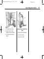
Spotlamp - SEO 7X6
This option includes one
pillar-mounted driver side halogen
spotlamp. The spotlamp has a fuse
located in the passenger side
underhood fuse block.
Spotlamps - SEO 7X7
SEO 7X7 includes a driver and a
passenger side spotlamp.
The spotlamp fuses are located in
the passenger side underhood fuse
block. See “Fuses and Circuit
Breakers” in the owner manual.
For spotlamp bulb replacement
procedures, see the appropriate
section of the service manual.
Black plate (16,1)
Chevrolet Impala Police Package - 2013 - CRC - 4/10/12
Black plate (17,1)
Special Equipment Options
Wiring Provisions for
Vehicle Grille Lamps and
Speaker/Siren - SEO 6J3
The SEO 6J3 wiring provision option
consists of a 1.5 m (5 ft) wiring
harness coiled underneath the
instrument panel on the passenger
side. The wiring circuits are routed
from underneath the instrument
panel to a 30 cm (1 ft) coil secured
in the area behind the grille. There
are four 1.0 mm² (16 gauge) wires
for connecting to the grille lights
(GRY, TAN) and siren speaker (LT
BU, LT GN).
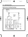
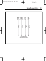
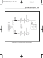
The SEO 6J3 wiring provision also
includes one 0.8 mm² (18 gauge)
control wire for the SEO 6J7 exterior
lamps emergency flashing system.
Alternating Signal Flasher
A. Blunt cut ends for the
Customer-Furnished Grille
Lamps and Customer-Furnished
Siren/Speaker
B. Control Wires from In-Line
Connector in Forward Lamp
Harness for
Customer-Furnished Grille
Lamps and Speaker
When option SEO 6J7 is installed
without option SEO 6J3, only the
dark green/red control wire is
provided for connection to
customer-furnished 12-volt
switching to turn the emergency
flashing system on or off.
15-17
Chevrolet Impala Police Package - 2013 - CRC - 4/10/12
15-18
Special Equipment Options
Wiring Diagram for SEO 6J3 and SEO 6J7
Black plate (18,1)
Chevrolet Impala Police Package - 2013 - CRC - 4/10/12
Black plate (19,1)
Special Equipment Options
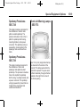
Spotlamp Provisions SEO 7X8
Trunk Lid Warning Lamps
- SEO T53
This option includes a provision for
the installation of a driver side
pillar-mounted spotlamp. The
provision includes a hole in the A
pillar for spotlamp shaft routing,
mounting bracket, and a power
connector. The spotlamp wiring is
powered by a fuse located in the
passenger side underhood fuse
block.
Spotlamp Provisions SEO 7X9
This option includes provisions for
the installation of driver and
passenger side pillar-mounted
spotlamps. The provision includes a
hole in the A pillar for spotlamp
shaft routing, mounting bracket, and
a power connector. The spotlamp
wiring is powered by fuses that are
located in the passenger side
underhood fuse block.
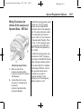
Two 10 cm (4 in) single faced lamps
are mounted to the inside of the
trunk lid. The lamps work while the
trunk lid is opened. They are wired
to flash alternately through a flasher
located at the right front corner of
the trunk opening.
15-19
Chevrolet Impala Police Package - 2013 - CRC - 4/10/12
15-20
Special Equipment Options
Wiring Provisions for
Horn/Siren Circuit SEO 6J4
This provision permits customer
connection of a switch to select
either horn or siren operation when
the horn pad is pressed.
A 0.35 mm² (22 gauge) wire is
connected to an in-line connector in
the horn circuit of the instrument
panel harness under the instrument
panel. The end of this harness
extension is in a 1.5 m (5 ft) loop of
wire coiled under the instrument
panel.
Black plate (20,1)
Chevrolet Impala Police Package - 2013 - CRC - 4/10/12
Black plate (21,1)
Special Equipment Options
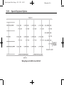
Wiring Diagram for SEO 6J4 Inline Connector
15-21
Chevrolet Impala Police Package - 2013 - CRC - 4/10/12
15-22
Special Equipment Options
Wiring Provisions for
Roof-Mounted
Accessories - SEO 6F5
A. 6B7 Hole Location
B. 6J5 Hole Location
Black plate (22,1)
Chevrolet Impala Police Package - 2013 - CRC - 4/10/12
Black plate (23,1)
Special Equipment Options
Wiring Diagram for SEO 6F5
15-23
Chevrolet Impala Police Package - 2013 - CRC - 4/10/12
15-24
Black plate (24,1)
Special Equipment Options
Option 6F5 is a universal wiring
harness for roof-mounted
equipment. The harness is routed
from a 1.5 m (5 ft) coil of wire in the
passenger side footwell to a
connector on the passenger side of
the trunk.
Wiring Provisions Front
Speakers - SEO WX7
Electrical Connections
1. Disconnect the negative (−)
battery cable at the battery.
When the SEO 6B7 (center hole) is
ordered, two color-coded 5.0 mm²
(10 gauge) wires extend 60 cm
(24 in) through a grommet
approximately 74 cm (30 in) behind
the top of the windshield at the
center of the roof.
When SEO 6J5 (passenger side
hole) is ordered, two color‐coded
5.0 mm² (10‐gauge) wires extend
60 cm (24 in) through a grommet
approximately 74 cm (30 in) behind
the top of the windshield and 15 cm
(6 in) inboard from the passenger
side longitudinal roof joint.
Radio outputs from the front
speakers are sent to the rear
speakers to maintain the required
open door/key in the ignition
reminder chime.
2. Remove the tape from the wire
coiled under the instrument
panel to uncoil it.
About 165 cm (65 in) of auxiliary
speaker wire is run from the
instrument panel radio connector
and is coiled under the center of the
instrument panel. The wiring permits
the connection of front door
speakers to customer-installed
communication equipment.
3. Using proper electrical
connectors, connect the wires
for the left front audio output of
the customer-installed
communication device. The left
front positive wire is tan and the
left front negative wire is gray.
4. Using proper electrical
connectors, connect the wires
for the right front audio output of
the customer-installed
communication device. The right
front positive wire is light green
and the right front negative wire
Chevrolet Impala Police Package - 2013 - CRC - 4/10/12
Black plate (25,1)
Special Equipment Options
is dark green. The electrical
impedance of each speaker
installed is 10 ohms.
Notice: Overloading the vehicle's
electrical system may damage
your vehicle's accessories. Do
not overload the vehicle's system
by having unnecessary
accessories on at the same time.
5. The ignition must be turned off
and the vehicle must be vacated
prior to attaching the cable to the
battery. Connect the negative (−)
battery cable to the battery and
tighten the bolt to 15 N·m
(11 lb ft).
6. Set the time on the clock and
radio pushbuttons as needed.
See “Audio System” in the
owner manual.
15-25
Chevrolet Impala Police Package - 2013 - CRC - 4/10/12
15-26
Special Equipment Options
Wiring Diagram for SEO WX7 Inline Connector
Black plate (26,1)
Chevrolet Impala Police Package - 2013 - CRC - 4/10/12
Black plate (27,1)
Special Equipment Options
Wiring Provisions Rear
Coaxial Cable - SEO 6C8
About 240 cm (95 in) of RG58
coaxial radio antenna cable is run
from the roof panel just rear of the
center dome lamp and coiled in the
trunk to reach either corner. The
cable permits the connection of
customer-installed communication
equipment.
15-27
Chevrolet Impala Police Package - 2013 - CRC - 4/10/12
15-28
Black plate (28,1)
Special Equipment Options
2 NOTES
Chevrolet Impala Police Package - 2013 - CRC - 4/10/12
Black plate (1,1)
INDEX
i-1
A
C
E
Accessories, Wiring
Provisions for
Roof-Mounted - SEO 6F5 . . . 15-22
Airbags
Deployment Diagrams . . . . . . . . . 3-4
Questions and Answers
About Airbags and
Specialty Law
Enforcement Vehicles . . . . . . . . 3-1
Auxiliary
Available Option . . . . . . . . . . . . . .15-8
Auxiliary Battery Power
Junction Blocks, Available
Option . . . . . . . . . . . . . . . . . . . . . . . . 15-8
Auxiliary Dome Lamp SEO
- 6C7 . . . . . . . . . . . . . . . . . . . . . . . . 15-11
Cable, Wiring Provisions
for Coaxial Cable SEO 6C8 . . . . . . . . . . . . . . . . . . . . 15-27
Canadian Vehicle Owners . . . . . . . . .ii
Circuit
Wiring Provisions for
Horn/Siren - SEO 6J4 . . . . . 15-20
Cluster, Instrument . . . . . . . . . . . . . 5-2
Compact Spare Tire . . . . . . . . . . . 10-2
Cooling
Heavy Duty System . . . . . . . . 15-10
Customer-installed
Equipment, Notices . . . . . . . . . . . 3-3
Electronic Stability Control . . . . . . 9-3
Electronic Stability Control
(ESC) Off Light . . . . . . . . . . . . . . . . 5-3
Engine
Oil Cooling System and
Power Steering . . . . . . . . . . . . . .15-2
Exterior Lamp Controls . . . . . . . . . 6-1
Exterior Lamp Emergency
Flashing System SEO 6J7 . . . . . . . . . . . . . . . . . . . . 15-13
B
Battery
Power Junction Blocks . . . . . . .15-8
Wiring Provisions for
12-Volt Power Supply . . . . . . .15-4
Brakes . . . . . . . . . . . . . . . . . . . . . . . . . 10-1
D
Deployment Diagrams . . . . . . . . . . 3-4
Dome Lamp Inoperative
Function - SEO 7Y6 . . . . . . . . . 15-12
Driver Information
Center (DIC) . . . . . . . . . . . . . . . . . . 5-4
Driving
Vehicle Load Limits . . . . . . . . . . . . 9-1
F
Fast Idle System . . . . . . . . . . . . . . . . 9-1
Flasher, Wiring Provisions
- SEO 6J3 . . . . . . . . . . . . . . . . . . . 15-17
Floor Covering
Heavy Duty - SEO 6A3 . . . . . 15-15
Full-Size Spare Tire . . . . . . . . . . . 10-3
Chevrolet Impala Police Package - 2013 - CRC - 4/10/12
i-2
Black plate (2,1)
INDEX
H
L
N
Heavy Duty Cooling
System . . . . . . . . . . . . . . . . . . . . . . 15-10
Heavy Duty Floor Covering
- SEO 6A3 . . . . . . . . . . . . . . . . . . 15-15
Horn/Siren, Wiring
Provisions - SEO 6J4 . . . . . . . 15-20
Lamp
Auxiliary Dome, SEO
- 6C7 . . . . . . . . . . . . . . . . . . . . . . .15-11
Lamps
Exterior Controls . . . . . . . . . . . . . . . 6-1
Exterior Emergency
Flashing System SEO 6J7 . . . . . . . . . . . . . . . . . . 15-13
Rear Panel - SEO 6J6 . . . . . . 15-15
Trunk Lid Warning SEO T53 . . . . . . . . . . . . . . . . . . 15-19
Vehicle Grille Wiring
Provisions - SEO 6J3 . . . . . 15-17
Light
Electronic Stability Control
(ESC), Off . . . . . . . . . . . . . . . . . . . . 5-3
Notices for
Customer-installed
Equipment . . . . . . . . . . . . . . . . . . . . 3-3
I
Idle System
Fast . . . . . . . . . . . . . . . . . . . . . . . . . . . 9-1
Ignition Control Trunk
Release - SEO A98 . . . . . . . . . 15-15
Inoperative Rear Door
Handles- SEO 6B2 . . . . . . . . . . 15-12
Inoperative Rear Door
Locks - SEO 6N6 . . . . . . . . . . . 15-15
Instrument Cluster . . . . . . . . . . . . . . 5-2
Introduction . . . . . . . . . . . . . . . . . . . . . . . .ii
K
Keys
Single Key Random Code
System . . . . . . . . . . . . . . . . . . . . . . . 2-1
M
Mat, Trunk . . . . . . . . . . . . . . . . . . . . 15-10
Messages
Ride Control System . . . . . . . . . . . 5-5
Monitor System, Tire
Pressure . . . . . . . . . . . . . . . . . . . . . 10-1
P
Police Package
SEO Available Options . . . . . .15-11
Police Package and Special
Service Package, SEO
Standard Options . . . . . . . . . . . . 15-2
Power Steering/Engine Oil
Cooling System . . . . . . . . . . . . . . 15-2
Q
Questions and Answers
About Airbags and
Specialty Law Enforcement
Vehicles . . . . . . . . . . . . . . . . . . . . . . . 3-1
Chevrolet Impala Police Package - 2013 - CRC - 4/10/12
Black plate (3,1)
INDEX
R
Radios . . . . . . . . . . . . . . . . . . . . . . . . 15-10
Rear Panel Lamps SEO 6J6 . . . . . . . . . . . . . . . . . . . . 15-15
Rear Windows Inoperative
- SEO 6N5 . . . . . . . . . . . . . . . . . . 15-15
Replacement Parts
Maintenance . . . . . . . . . . . . . . . . . . 11-2
Ride Control Systems . . . . . . . . . . 9-3
Electronic Stability (ESC) . . . . . . 9-3
Messages . . . . . . . . . . . . . . . . . . . . . 5-5
Roof-Mounted
Accessories, Wiring
Provisions - SEO 6F5 . . . . . . . 15-22
S
Safety Belts
Questions and Answers
About Airbags and
Specialty Law
Enforcement Vehicles . . . . . . . . 3-1
Seats . . . . . . . . . . . . . . . . . . . . . . . . . 15-10
SEO Available Options
Police Package . . . . . . . . . . . . . .15-11
SEO Standard Options
Police Package and
Special Service Package . . . .15-2
Spare Tire
Compact . . . . . . . . . . . . . . . . . . . . . .10-2
Speaker/Siren, Wiring
Provisions - SEO 6J3 . . . . . . . 15-17
Speakers
Wiring Provisions, Front SEO WX7 . . . . . . . . . . . . . . . . . 15-24
Special Equipment Options
Dome Lamp Inoperative
Function - SEO 7Y6 . . . . . . . 15-12
Heavy Duty Floor
Covering - SEO 6A3 . . . . . . 15-15
Ignition Control Trunk
Release - SEO A98 . . . . . . . 15-15
Spotlamp Provisions SEO 7X8 . . . . . . . . . . . . . . . . . . 15-19
Spotlamp Provisions SEO 7X9 . . . . . . . . . . . . . . . . . . 15-19
Specific Cylinder Unit for
Single Key - Random Code
System . . . . . . . . . . . . . . . . . . . . . . . . 2-1
Spotlamp
SEO 7X6 . . . . . . . . . . . . . . . . . . . 15-16
i-3
Spotlamp Provisions SEO 7X8 . . . . . . . . . . . . . . . . . . . . 15-19
Spotlamps
SEO 7X7, Available
Option . . . . . . . . . . . . . . . . . . . . . 15-16
Supplement
Using . . . . . . . . . . . . . . . . . . . . . . . . . . . . ii
System
Heavy Duty Cooling . . . . . . . . 15-10
T
Tires
Compact Spare . . . . . . . . . . . . . . .10-2
Full-Size Spare . . . . . . . . . . . . . . .10-3
Pressure Monitor System . . . . .10-1
Towing
Trailer . . . . . . . . . . . . . . . . . . . . . . . . . 9-5
Traction
Control System (TCS) . . . . . . . . . 9-2
Trailer
Towing . . . . . . . . . . . . . . . . . . . . . . . . . 9-5
Trunk Ground Stud . . . . . . . . . . . . 15-3
Trunk Lid Warning Lamps SEO T53 . . . . . . . . . . . . . . . . . . . . 15-19
Trunk Mat . . . . . . . . . . . . . . . . . . . . 15-10
Chevrolet Impala Police Package - 2013 - CRC - 4/10/12
i-4
INDEX
Trunk Release
Ignition Controlled SEO A98 . . . . . . . . . . . . . . . . . . 15-15
U
Using This Supplement . . . . . . . . . . . .ii
V
Vehicle
Canadian Owners . . . . . . . . . . . . . . . ii
Load Limits . . . . . . . . . . . . . . . . . . . . 9-1
W
Wiring Provisions
12-Volt Battery Power
Supply . . . . . . . . . . . . . . . . . . . . . .15-4
Front Speakers SEO WX7 . . . . . . . . . . . . . . . . . 15-24
Horn/Siren Circuit SEO 6J4 . . . . . . . . . . . . . . . . . . 15-20
Wiring Provisions (cont'd)
Rear Coaxial Cable SEO 6C8 . . . . . . . . . . . . . . . . . . 15-27
Roof-Mounted
Accessories - SEO 6F5 . . . 15-22
Vehicle Grille Lamps, and
Speaker/Siren SEO 6J3 . . . . . . . . . . . . . . . . . . 15-17
Black plate (4,1)