1
2010 Chevrolet Tahoe Police and Special Service Packages M
Seats and Restraint System . . . . . . . . . . . . . . . . . . . . . . 2-1
Airbag System . . . . . . . . . . . . . . . . . . . . . . . . . . . . . . . . . . . . 2-2
Features and Controls . . . . . . . . . . . . . . . . . . . . . . . . . . . . 3-1
Keys . . . . . . . . . . . . . . . . . . . . . . . . . . . . . . . . . . . . . . . . . . . . . 3-2
Starting and Operating Your Vehicle . . . . . . . . . . . . . . 3-3
Instrument Panel . . . . . . . . . . . . . . . . . . . . . . . . . . . . . . . . .
Instrument Panel . . . . . . . . . . . . . . . . . . . . . . . . . . . . . . . . .
Warning Lights, Gages, and Indicators . . . . . . . . . . .
Driver Information Center (DIC) . . . . . . . . . . . . . . . . . . .
4-1
4-2
4-2
4-5
Driving Your Vehicle . . . . . . . . . . . . . . . . . . . . . . . . . . . . . . 5-1
Your Driving, the Road, and the Vehicle . . . . . . . . . . 5-2
Towing . . . . . . . . . . . . . . . . . . . . . . . . . . . . . . . . . . . . . . . . . . . 5-5
Service and Appearance Care . . . . . . . . . . . . . . . . . . .
Checking Things Under the Hood . . . . . . . . . . . . . . . .
Tires . . . . . . . . . . . . . . . . . . . . . . . . . . . . . . . . . . . . . . . . . . . . . .
Capacities and Specifications . . . . . . . . . . . . . . . . . . . .
6-1
6-2
6-2
6-3
Special Equipment Options . . . . . . . . . . . . . . . . . . . . . 15-1
SEOs Available with Police Package and
Special Service Package . . . . . . . . . . . . . . . . . . . . . . 15-2
SEOs Standard with Police Package and
Special Service Package . . . . . . . . . . . . . . . . . . . . . 15-18
Index . . . . . . . . . . . . . . . . . . . . . . . . . . . . . . . . . . . . i-1
Chevrolet Tahoe Police and Special Service Packages - 2010
Black plate (2,1)
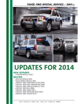
The Tahoe Special Service Package (SEO 5W4) is not
designed nor intended for use in high‐speed emergency
vehicle operations.
Canadian Owners
Propriétaires Canadiens
GENERAL MOTORS, GM, the GM Emblem,
CHEVROLET, the CHEVROLET Emblem, and
the name TAHOE are registered trademarks of
General Motors LLC.
A French language copy of this manual can be obtained
from your dealer/retailer or from:
On peut obtenir un exemplaire de ce guide en français
auprès du concessionnaire ou à l'adresse suivante:
Helm, Incorporated
P.O. Box 07130
Detroit, MI 48207
This manual describes features that may or may not
be on your specific vehicle either because they are
options that you did not purchase or due to changes
subsequent to the printing of this owner manual.
Please refer to the purchase documentation relating to
your specific vehicle to confirm each of the features
found on your vehicle. For vehicles first sold in Canada,
substitute the name “General Motors of Canada
Limited” for Chevrolet Motor Division wherever it
appears in this manual.
Numéro de poste 6438 de langue française
The Tahoe Police Package (SEO PPV) has been
designed for police work up to and including high‐speed
emergency vehicle operations.
To quickly locate information about the vehicle, use the
index in the back of the manual. It is an alphabetical list
of what is in the manual and the page number where it
can be found.
Litho in U.S.A.
Part No. 20880109 B Second Printing
ii
1-800-551-4123
www.helminc.com
Index
©
2010 General Motors LLC. All Rights Reserved.
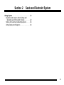
Section 2
Seats and Restraint System
Airbag System . . . . . . . . . . . . . . . . . . . . . . . . . . . . . . . . . . . . .
Questions and Answers About Airbags and
Specialty Law Enforcement Vehicles . . . . . . . . . .
Notices for Customer-Installed Equipment . . . . . .
Airbag Deployment Diagrams . . . . . . . . . . . . . . . . . . .
2-2
2-2
2-5
2-6
2-1
Airbag System
Questions and Answers About
Airbags and Specialty Law
Enforcement Vehicles
Q: Can equipment such as radar devices, video
cameras, and radio trees be mounted in a
specialty vehicle equipped with a right front
passenger's frontal airbag?
A: Yes, but care must be taken to properly mount the
equipment outside of the airbag “deployment zone.”
2-2
Q: What is the airbag “deployment zone”?
A: The term “deployment zone” describes the space an
airbag takes up when fully inflated. Airbags need
room to work properly, and anything in the
“deployment zone” — such as improperly mounted
equipment — can greatly affect the performance of
the airbag.
{ WARNING:
Airbags inflate with great force, faster than the
blink of an eye. No objects, such as shotguns,
should be placed over or near the airbag covers.
Equipment mounted too close to an inflating
airbag could break and become a dangerous
projectile in a crash, causing injury to the vehicle's
occupants. Also, an object too close to an inflating
(Continued)
WARNING: (Continued)
airbag could prevent the airbag from operating
properly. If this ever happens, the airbag would
not be able to protect occupants the way it was
designed to. To help prevent injury and to allow
the airbag to perform as it was designed,
do not mount equipment inside the airbag
deployment zone.
Q: How can I identify the airbag “deployment zone”
in my vehicle?
A: See Airbag Deployment Diagrams on page 2‑6
for more information. The diagrams provide the
approximate dimensions of the “deployment zones”
for your specialty vehicle. Before doing any service
work, including the installation of any equipment,
consult the appropriate service manual.
Q: Is it possible to shield equipment so it does not
interfere with airbag deployment?
A: While shielding may protect certain equipment from
being damaged or dislodged, it may also negatively
affect how an airbag inflates. Therefore, we cannot
recommend the placement of any equipment in the
deployment zone, even when shielding.
2-3
Q: Can the installation of push bumpers on the
front end of the vehicle affect the deployment of
the airbag?
Q: Is there anything I might add to the exterior of
the vehicle that could keep the airbags from
working properly?
A: Yes, particularly if the push bumper significantly
changes the front structure of the vehicle. However,
GM conducts analysis on various push bumper
configurations to verify effectiveness of the sensing
performance system with minor changes in the front
structure of the vehicle which may occur from the
addition of a push bumper.
A: Yes. If you add things that change your vehicle's
frame, bumper system, height, front end or side
sheet metal, they may keep the airbag system from
working properly. Also, the airbag system may not
work properly if you relocate any of the airbag
sensors. If you have any questions about this, you
should contact Customer Assistance before you
modify your vehicle. The phone numbers and
addresses for Customer Assistance are in Step Two
of the Customer Satisfaction Procedures in the
owner's manual. See “Customer Satisfaction
Procedure” in your owner's manual index.
If your vehicle has rollover roof-rail airbags, see
“Different Size Tires and Wheels” in your owner's
manual for additional important information.
The service manual has information about the location
of the airbag sensors, sensing and diagnostic module,
and airbag wiring. See “Service Publications Ordering
Information” in your owner's manual.
2-4
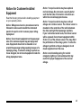
Notices for Customer-Installed
Equipment
Read the following notices before installing equipment
on your specialty vehicle.
Notice: GM-approved service procedures must be
followed to remove and reinstall the instrument
panel to the pad in order to ensure proper airbag
deployment.
Notice: Do not mount equipment on the passenger
side of the instrument panel top pad deployment
zone. Equipment should not be mounted on or
around the passenger airbag opening because of a
deploying airbag. To allow the airbag to perform as
it was designed, do not mount equipment inside the
airbag deployment zone.
Notice: Your police vehicle may have optional
roof-rail airbags. Do not mount a security barrier
such that the ends of the barrier or brackets are
within the roof-rail deployment zones.
Notice: Your police vehicle may have roof-rail
airbags and a rollover sensor. The rollover sensor is
mounted on the centerline of the vehicle between
the driver and right front passenger positions.
If your vehicle has bucket seats, the rollover sensor
will be exposed. Do not mount equipment within
25 mm (1 in) of the rollover sensor. This may affect
the performance of the airbag system. To allow the
airbags to perform as they are designed, do not
mount equipment near this area.
Notice: Avoid installing wiring for roof-rail
emergency lighting or radio antennas that may
restrict the proper deployment of the roof-rail
airbags.
2-5
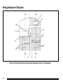
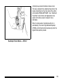
Airbag Deployment Diagrams
Top View of Instrument Panel and Approximate Deployment Area of the Airbag Zone
2-6
A. Passenger Side Instrument Panel Top
Surface Zone
H. Vehicle Centerline
B. Passenger Side Airbag Module
Trim Panel — Rear Edge
J. Driver Side Airbag Deployment Zone
C. Passenger Side Door
D. Approximate Dimensions of Inflated Airbag
E. Passenger Side Airbag Deployment Zone
F. Passenger Centerline
I. Driver Centerline
K. Front of Steering Wheel
L. Driver Side Door
M. Shift Selector Arc
See Notices for Customer-Installed Equipment on
page 2‑5 for more information.
G. Inside Rearview Mirror
2-7
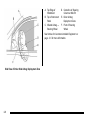
A. Top Edge of
Windshield
D. Centerline of Steering
Column at Mid-Tilt
B. Top of Instrument
Panel
E. Driver Airbag
Deployment Zone
C. Inflated Airbag —
Steering Wheel
F. Front of Steering
Wheel
See Notices for Customer-Installed Equipment on
page 2‑5 for more information.
Side View of Driver Side Airbag Deployment Zone
2-8
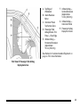
B. Inside Rearview
Mirror
F. Inflated Airbag —
Vertical Dimension
(Approximate
19.3 in (490 mm))
C. Instrument Panel
Top Surface Zone
G. Inflated Airbag —
Instrument Panel
D. Passenger Side
Airbag Module Trim
Panel — Rear Edge
H. Passenger Airbag
Deployment Zone
A. Top Edge of
Windshield
E. Inflated Airbag —
Horizontal Dimension
(Approximate
15.4 in (390 mm))
See Notices for Customer-Installed Equipment on
page 2‑5 for more information.
Side View of Passenger Side Airbag
Deployment Zone
2-9
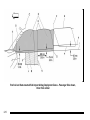
Roof-rail and Seat‐mounted Side Impact Airbag Deployment Zones - Passenger Side shown,
Driver Side similar
2-10
A. Front of Deployment Zone at Front Upper Corner
of Front Door Pad
J. Dimension at Mirror Patch from Top Edge of Front
Door Pad
B. Windshield Pillar Trim with Grab Handle
K. Center of Door Trim Pull Handle
C. Visor
L. Top Surface of Outboard Seat Cushion
D. Deployment Zone
M. Top Edge of Front Door Pad
E. Top of Deployment Zone — Along Roof-rail at
Edge of Headliner
O. Top Edge of Rear Door Pad
N. Back Edge of Center Pillar Trim
F. Back of Deployment Zone — At Rear Top Corner
of Rear Door Pad
P. Bottom Outside Edge of Rear Quarter Window
G. Rear Quarter Window
See Notices for Customer-Installed Equipment on
page 2‑5 for more information.
H. Top Edge of Interior Quarter Trim
I. Bottom of Airbag Deployment Zone — Parallel to
Outside Bottom Edge of Rear Quarter Glass
2-11
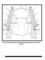
Roof-rail and Seat‐mounted Side Impact Airbag Driver and Passenger Deployment Zones - View from Rear
Cargo Area
2-12
A. Roof-rail Airbag Deployment Zone
B. Underside of Headliner
H. Inner Door Pad
C. Edge of Headliner
I. Seat‐mounted Side Impact Airbag deployment
Zone — Front Seat
D. Inner Center Pillar Trim
J. Top Surface of Outboard Front Seat Cushion
E. Bottom of Door Windows
F. Front Seat Headrest
See Notices for Customer-Installed Equipment on
page 2‑5 for more information.
G. Seat Centerline
2-13
2 NOTES
2-14
Section 3
Features and Controls
Keys . . . . . . . . . . . . . . . . . . . . . . . . . . . . . . . . . . . . . . . . . . . . . . . . 3-2
Specific Cylinder Unit for Single Key - Random
Code System . . . . . . . . . . . . . . . . . . . . . . . . . . . . . . . . . 3-2
Starting and Operating Your Vehicle . . . . . . . . . . . . . . 3-3
Running the Vehicle While Parked . . . . . . . . . . . . . . 3-3
3-1
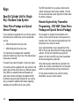
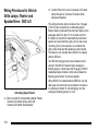
Keys
Specific Cylinder Unit for Single
Key - Random Code System
Tahoe Police Package and Special
Service Package
If your vehicles are equipped with one of these options,
the entire fleet of vehicle locks can be operated with
one key.
.
SEO 6E2-Specific Fleet Key Code
.
SEO 6E8-Specific Fleet Key Code
Your vehicle will be equipped with a standard
production random key code if one of the optional fleet
codes was not ordered.
For specific key code information, contact your dealer.
Your vehicles will be equipped with a key cylinder in the
ignition lock and the driver's door only. Remote keyless
entry (RKE) is a standard feature and operates all
other doors and the rear liftgate. Six additional RKE
transmitters may have been ordered with your vehicle.
See your dealer for additional information regarding
availability of more RKE units for your vehicle.
3-2
The RKE transmitter for your police vehicle has the
vehicle locator/panic alarm button disabled. The horn
will not sound and the exterior lights will not flash when
the button is pressed.
Remote Keyless Entry Transmitter
Programming ‐ SEO AMF (Tahoe Police
Package and Special Service Package)
Do not operate or program the transmitters in the
vicinity of other vehicles that are in the keyless entry
program mode. This prevents the programming of the
transmitters to the incorrect vehicle.
Up to eight transmitters may be programmed to the
RKE on Police and Special Service Package equipped
vehicles. The first four transmitters are given the
position of #1‐#4 in the RKE. Any further transmitters
will also be assigned to position #4.
Verify that the proper transmitters are learned to the
vehicle. Do not learn a transmitter with a remote start
button to a vehicle that does not have remote start.
For the proper procedure to be used for learning
transmitters, see your owner's manual.
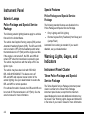
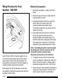
Starting and Operating Your
Vehicle
Engine Idle Speed - Alternator Output
(Tahoe Police Package and Special
Service Package)
Running the Vehicle While Parked
Normal idle speed for the engine is set for 600 rpm.
To increase alternator output while the transmission
remains in P (Park) or N (Neutral), and the electrical
load on the alternator is large enough, the engine idle
speed can rise to as high as 800 to 1000 rpm.
Tahoe Police Package and Special
Service Package
While parked with the engine idling for an extended
period, turn off the following factory equipment if
emergency lighting and communication equipment are
operating:
.
Air Conditioner
.
Fan
.
Rear Window Defogger
.
Factory Audio System
See “Running the Vehicle While Parked” in the owner
manual Index.
3-3
2 NOTES
3-4
Section 4
Instrument Panel
Instrument Panel . . . . . . . . . . . . . . . . . . . . . . . . . . . . . . . . . . . 4-2
Exterior Lamps . . . . . . . . . . . . . . . . . . . . . . . . . . . . . . . . . . 4-2
Warning Lights, Gages, and Indicators . . . . . . . . . . .
Instrument Panel Cluster . . . . . . . . . . . . . . . . . . . . . . . .
Speedometer and Odometer . . . . . . . . . . . . . . . . . . . .
Driver Information Center (DIC) . . . . . . . . . . . . . . . . . . .
4-2
4-2
4-5
4-5
4-1
Instrument Panel
Special Features
Exterior Lamps
Police Package and Special Service
Package
Police Package and Special Service
Package
The following standard features are disabled in the
Police Package and Special Service Package.
The following exterior lighting features apply to vehicles
first sold in the United States.
The vehicle has Daytime Running Lamps (DRL) and an
Automatic Headlamp System (AHS). The DRL and AHS
can be turned to OFF with the headlamp switch when
the transmission is in P (Park) and the engine is at idle.
If the engine is not turned off, the DRL and AHS will
remain OFF when the transmission is placed in gear.
The vehicle may be driven with the lamps off for one
ignition cycle.
The vehicle may have been built with SEO 9G8,
DRL AND AHS DISABLE. This feature turns off
DRL and AHS and requires manual control of the
exterior lighting. See your dealer/retailer to restore the
DRL and AHS to normal operation.
For vehicles first sold in Canada, the DRL and AHS can
be turned off if the transmission is in P (Park). See the
owner's manual for more information.
4-2
.
Entry Lighting and Exit Lighting
.
Remote Keyless Entry Feedback (Horn Beep) and
(Lamps Flash)
Automatic Door Locking is standard. If you need it
disabled, see your dealer/retailer.
Warning Lights, Gages, and
Indicators
Instrument Panel Cluster
Tahoe Police Package and Special
Service Package
The Tahoe Special Service Package instrument panel
cluster is similar to the Tahoe Police Package
instrument panel cluster, except that the maximum
speed displayed is lower and additional indicators may
be present. See “Warning Lights, Gages and Indicators”
in the Index of your owner manual for more information.
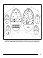
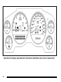
Tahoe Police Package 6‐Speed Automatic Transmission (United States version shown, Canada similar)
4-3
Special Service Package 4‐ Speed Automatic Transmission (United States version shown, Canada similar)
4-4
Speedometer and Odometer
Driver Information Center (DIC)
Tahoe Police Package and Special
Service Package
Tahoe Police Package and Special
Service Package
Your speedometer lets you see your speed in both
miles per hour (mph) and kilometers per hour (km/h).
Your odometer shows how far your vehicle has been
driven, either in miles (United States) or kilometers
(Canada).
The Tahoe Police Package and Special Service
Packages do not have DIC buttons. You can turn off or
acknowledge the available DIC messages by using the
trip odometer reset stem located on the instrument
panel cluster. See your owner's manual for additional
information on the DIC.
The speedometer for the Tahoe Police Package
(SEO PPV) displays a maximum vehicle speed of
140 mph (225 km/h). The speedometer for the Tahoe
Special Service Package (SEO 5W4) displays a
maximum vehicle speed of 120 mph (193 km/h). The
Tahoe Special Service Package is not designed nor
intended for use in high‐speed emergency vehicle
operations.
4-5
2 NOTES
4-6
Section 5
Driving Your Vehicle
Your Driving, the Road, and the Vehicle . . . . . . . . . . 5-2
Loading the Vehicle . . . . . . . . . . . . . . . . . . . . . . . . . . . . . 5-2
Towing . . . . . . . . . . . . . . . . . . . . . . . . . . . . . . . . . . . . . . . . . . . . . 5-5
Towing a Trailer . . . . . . . . . . . . . . . . . . . . . . . . . . . . . . . . . 5-5
5-1
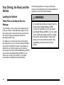
Your Driving, the Road, and the
Vehicle
Loading the Vehicle
Tahoe Police and Special Service
Package
The information in this section of the supplement is for
those who intend to install additional equipment to the
police vehicle after it has left the factory, and for those
who will be driving and loading the vehicle with
passengers and/or cargo.
Two labels on your vehicle show how much weight it
was designed to carry, the Tire and Loading Information
label and the Certification/Tire label. These labels are
attached to your vehicle and give you the maximum
load capacity, the Gross Vehicle Weight Rating (GVWR)
and the Gross Axle Weight Rating (GAWR) for your
vehicle. See “Loading Your Vehicle” in your owner
manual Index for additional loading information.
5-2
The following guidelines can help you with proper
loading and load distribution when installing additional
equipment on the Tahoe Police Package.
{ WARNING:
Do not load the vehicle any heavier than the
Gross Vehicle Weight Rating (GVWR),
or either the maximum front or rear Gross
Axle Weight Rating (GAWR). If you do, parts
on the vehicle can break, and it can change
the way the vehicle handles. These could
cause you to lose control and crash. Also,
overloading can shorten the life of the
vehicle.
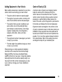
Adding Equipment to Your Vehicle
Center of Gravity (CG)
Before adding accessories or equipment to your police
vehicle, there are some things you need to know:
A vehicle's center of gravity is an imaginary location
inside the vehicle and is a balance point for the
vehicle mass as it moves down the road. The police
vehicle's center of gravity, before you add a load and
passengers, is approximately midway between the
center of the axles, up from the ground to just below the
front window, and between the driver and passenger.
.
The police vehicle's maximum capacity weight.
.
The weight of your police vehicle, including a full
tank of fuel but without a driver and passengers.
.
The weight of items you plan on adding to your
police vehicle, like roof mounted light bar(s),
push bumpers, security barrier(s), rear storage
organizer, highway flares, fire extinguishers,
weapons, ammunition, radios, and video
equipment.
.
The weight and number of passengers you intend
to carry in your vehicle.
.
The total weight of any additional cargo you intend
to carry in your vehicle.
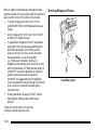
Equipment location and weight on the vehicle's center
of gravity is important to keep in mind when planning an
installation. Heavy equipment should be positioned as
low and as far forward in the rear load compartment as
possible. Try to mount the equipment below the bottom
of the side windows. Refer to the Loading Zone chart
and diagram to help with your installation plan.
When planning your vehicle equipment installation
remember not to exceed the Gross Vehicle Weight
Rating (GVWR) or the Gross Axle Weight Rating
(GAWR) of the front or rear axles. To keep the available
load weight less than the vehicle capacity weight, you
may need to limit the number of passengers you carry
in your vehicle or change your choice of additional
equipment.
5-3
A procedure to make the necessary measurements and
formulas to calculate the vehicle longitudinal, lateral and
vertical position of the center of gravity can be found in
the GM Coachbuilders Manual. Equipment required to
conduct the measurements for calculating the center of
gravity are:
.
Weight scales of sufficient capacity to measure the
vehicle weight at each wheel.
.
A post‐type hoist or other means to safely elevate
the front of the vehicle to at least an angle of
20 degrees above horizontal.
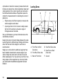
Loading Zones
See your GM dealer to get more information about this
coachbuilder procedure.
Keeping the center of gravity midway between the axles
is also important to provide proper braking performance.
About half the total vehicle weight on each axle is
recommended.
Weigh your vehicle after the additional equipment has
been installed to determine the actual weight of your
vehicle. Weigh the vehicle with a full tank of fuel and
without passengers. You may need to put a limit on how
many people or other equipment you can carry inside
your vehicle after the additional equipment has been
installed.
5-4
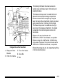
A. Front Floor to Roof
Zone Area
D. Rear Roof Zone Area
B. Front Roof Zone Area
E. Rear Floor to Roof
Zone Area
C. Back of Front Door
F. Ground
Loading Zone Weight Chart
Loading
Front Axle
Rear Axle
Zones
Weight
Weight
30 lbs
41 lbs
Roof
(14 kg)
(18 kg)
Floor
108 lbs.
429 lbs.
to Roof
(49 kg)
(195 kg)
138 lbs
470 lbs
Total
(63 kg)
(213 kg)
Towing
Total
71 lbs
(32 kg)
537 lbs.
(244 kg)
608 lbs
(276 kg)
Towing a Trailer
The Tahoe Police Package (SEO PPV) is not intended
to tow a trailer.
The Tahoe Special Service Package (SEO 5W4) can be
equipped for trailer towing. See “Towing a Trailer” in the
owner's manual Index for more information.
Using heavier suspension components to get added
durability might not change your weight ratings. Ask
your dealer to help you load your vehicle the right way.
5-5
2 NOTES
5-6
Section 6
Service and Appearance Care
Checking Things Under the Hood . . . . . . . . . . . . . . . . . 6-2
Dual Battery System - SEO 6A6 . . . . . . . . . . . . . . . . 6-2
Tires . . . . . . . . . . . . . . . . . . . . . . . . . . . . . . . . . . . . . . . . . . . . . . . . 6-2
Tire Pressure Monitor System . . . . . . . . . . . . . . . . . . . 6-2
Capacities and Specifications . . . . . . . . . . . . . . . . . . . . . 6-3
6-1
Checking Things Under
the Hood
Dual Battery System - SEO 6A6
This vehicle may have a dual battery system. The two
batteries are connected so that both supply battery
power to the vehicle at the same time — they are
connected in parallel. See “Battery” in the owner
manual Index for additional information on batteries.
Tires
Tahoe Police and Special Service
Packages
The Tahoe Police Package, SEO PPV, has
Goodyear P265/60R17 All Season Touring BW,
H speed‐rated tires. The Special Service Package,
SEO 5W4, has P265/70R17 BW OOR
On‐Off‐Road or P265/70R17 BW AL2 Touring
tires. The Special Service Package is not
designed nor intended for use in high‐speed
emergency vehicle operations.
6-2
Wheels
Metal hub caps are standard with SEO PPV.
These caps are bolted to the wheels and do not
require removal when rotating or removing the
wheels. Loosening or tightening the decorative
wheel attachment nuts can be done with the hub
caps in place.
Tire Pressure Monitor System
The Tahoe Police and Special Service Packages
may have a Tire Pressure Monitor System (TPMS).
Sensors are mounted on each tire and wheel assembly.
Only the Tahoe Police Package (SEO PPV) has a TPM
sensor in the full‐size spare tire and wheel assembly.
The TPM system will not monitor or display the spare
tire's air pressure until it is installed onto one of the
four tire/wheel positions on your vehicle.
Once installed, the spare tire's sensor code must be
matched its new tire/wheel position on your vehicle.
See “Tire Pressure Monitor System” in your owner
manual Index for information about the TPM system.
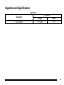
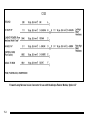
Capacities and Specifications
Capacities
Application
Cooling System
Capacities
English
18.1 quarts
Metric
17.1 L
6-3
2 NOTES
6-4
Section 15
Special Equipment Options
SEOs Available with Police Package and
Special Service Package . . . . . . . . . . . . . . . . . . . . . . . 15-2
Exterior Lamp Emergency Flashing
System - SEO 6J7 . . . . . . . . . . . . . . . . . . . . . . . . . . . 15-2
Inactive Rear Door Handles - SEO 6B2 . . . . . . . . 15-5
Inactive Rear Door Windows - SEO 6N5 . . . . . . . 15-5
Inactive Rear Door Locks - SEO 6N6 . . . . . . . . . . 15-5
Spotlamp - SEO 7X6 . . . . . . . . . . . . . . . . . . . . . . . . . . 15-5
Spotlamps - SEO 7X7 . . . . . . . . . . . . . . . . . . . . . . . . . 15-6
Wiring Provisions for Horn/Siren
Circuit - SEO 6J4 . . . . . . . . . . . . . . . . . . . . . . . . . . . . 15-6
Wiring Provisions for Vehicle Grille Lamps,
Flasher and Speaker/Siren - SEO 6J3 . . . . . . . 15-8
Wiring Provisions for Front
Speakers - SEO WX7 . . . . . . . . . . . . . . . . . . . . . . 15-10
Wiring Provisions for Emergency Vehicle
Roof Light - SEO TRW . . . . . . . . . . . . . . . . . . . . . 15-12
SEOs Standard with Police Package and
Special Service Package . . . . . . . . . . . . . . . . . . . . . .
Special Equipment Options Standard with
Tahoe Police Package . . . . . . . . . . . . . . . . . . . . . .
Equipment Grounding Studs - Rear
Compartment . . . . . . . . . . . . . . . . . . . . . . . . . . . . . . .
Radio Suppression Grounding Straps . . . . . . . .
Auxiliary Battery Power Junction Block(s) . . . .
Wiring Provisions for 12-Volt Power Supply . . .
15-18
15-18
15-19
15-19
15-20
15-21
15-1
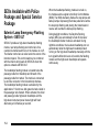
SEOs Available with Police
Package and Special Service
Package
Exterior Lamp Emergency Flashing
System - SEO 6J7
SEO 6J7 provides a high-beam headlamps flashing
module, rear lamps flashing and control wire for a
customer-furnished switch to turn the module on or off.
The flasher control wire is coiled under the center of the
instrument panel. This control lead may be combined
with the interior wiring leads for SEO 6J3 when that
option is ordered with SEO 6J7.
The headlamps flashing module is located below the
passenger side front headlamp and forward of the
passenger side front wheel. The module is connected
to an inline connector in the forward lamp harness.
The headlamps flashing module is activated by the
application of 12 volts to a dark green/red wire coiled in
the passenger side footwell. When activated, the driver
and passenger side high-beam headlamps and the
high-beam instrument panel cluster light will flash
alternately at 2.4 flashes per second.
15-2
When the headlamps flashing module is turned on,
the module sends a signal to the Body Control Module
(BCM). The BCM alternately flashes the stop lamps and
backup lamps. Depressing the brake pedal will override
the stop lamp flashing and placing the transmission in
reverse will override the backup lamp flashing.
During daylight conditions, the Daytime Running
Lamps (DRL) are automatically turned off whenever
the headlamps flasher module is activated. During
nighttime conditions, the low-beam headlamps turn on
automatically while the high-beam headlamps flash.
Turning on the high-beam headlamps manually with the
turn signal/multifunction lever will override the flashing
module and the high-beam headlamps will operate
continuously.
A 20 amp fuse protects the flasher module circuit.
This fuse is located in the underhood fuse block in the
engine compartment on the driver side of the vehicle
and is labelled HEADLAMP WASH . See “Underhood
Fuse Block” in the Service and Appearance Care
section of the Tahoe owner's manual for more
information.
When it is dark outside, the taillamps will turn on
automatically. The Center High-Mounted Stoplamp
(CHMSL) will not flash and will operate only when the
regular brake pedal is pressed.
Headlamps Flasher Module — SEO 6J7
15-3
Forward Lamp Harness In-Line Connector for use with Headlamps Flasher Module, Option 6J7
15-4
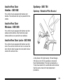
Inactive Rear Door
Handles - SEO 6B2
Spotlamp - SEO 7X6
Spotlamp ‐ Windshield Pillar Mounted
Your vehicle may be equipped with inactive door
handles. The rear doors can only be opened from the
outside.
Inactive Rear Door
Windows - SEO 6N5
Your vehicle may be equipped with inactive rear door
window control switches. Only the driver's power
window switches can operate the rear windows.
Inactive Rear Door Locks - SEO 6N6
Your vehicle may be equipped with inactive rear door
locks. The rear door locks do not lock or unlock at the
door. Only the driver's power door lock switch locks or
unlocks the rear door locks.
A Unity Series 330, high intensity, 100 watt halogen
(H3 bulb) six inch (15 cm) spotlamp is mounted in
the left windshield pillar. The lamp is protected by a
15 amp fuse located in the underhood electrical center.
See the service manual for lamp replacement
procedures.
15-5
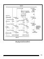
Wiring Provisions for Horn/Siren
Circuit - SEO 6J4
Spotlamp Harness ‐ SEO 7X6, SEO 7X7
Spotlamps - SEO 7X7
SEO 7X7 includes a driver side and a passenger side
spotlamp located in the windshield pillars. Each
spotlamp is protected by a separate 15 amp fuse
located in the underhood electrical center.
For spotlamp bulb replacement procedures, see the
appropriate section of the service manual.
15-6
This provision permits customer connection of a switch
to select either horn or siren operation when the horn
pad is pressed.
A 22 gauge (0.35 mm²) wire is connected to an in-line
connector in the horn circuit of the instrument panel
harness under the instrument panel. The end of this
harness extension is in a 5 foot (1.5 m) loop of wire
coiled under the center of the instrument panel.
Wiring Diagram for SEO 6J4 Inline Connector
15-7
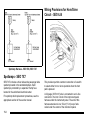
Wiring Provisions for Vehicle
Grille Lamps, Flasher and
Speaker/Siren - SEO 6J3
B. Control Wires from In-Line Connector in Forward
Lamp Harness for Customer-Furnished Grille
Lamps and Speaker
This wiring provision option consists of one 16 gauge
(1.0 mm²) wire connected to an alternating signal
flasher located underneath the instrument panel on the
passenger side. Five feet (1.5 m) of extra wire from
the flasher is routed from underneath the instrument
panel to an area behind the grille. All four wires have
12 inches (30 cm) of extra wire in a coil behind the
grille. Grille lamps and the speaker are not included.
The flasher is not included when SEO 6J7 is ordered
without SEO 6J3.
The SEO 6J3 wiring provision also includes control
wiring for the SEO 6J7 exterior lamps emergency
flashing system. A dark green/red 18 gauge (0.8 mm²)
headlamps flasher module control wire activates the
flashing system when 12‐volts are applied.
Alternating Signal Flasher
A. Blunt cut ends for the Alternating Signal Flasher,
Customer-Furnished Grille Lamps and
Customer-Furnished Siren/Speaker
15-8
When SEO 6J7 is installed without SEO 6J3, only the
dark green red control wire is provided for connection
to customer-furnished 12-volt switching to turn the
emergency flashing system on or off.
Wiring Diagram for SEO 6J3 and SEO 6J7
15-9
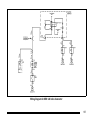
Wiring Provisions for Front
Speakers - SEO WX7
Electrical Connections
1. Disconnect the negative (−) battery cable at the
battery.
2. Remove the tape from the wire coiled under the
instrument panel to uncoil it.
3. Using proper electrical connectors, connect the
wires for the left front audio output of the
customer-installed communication device.
The left front positive wire is tan and the left front
negative wire is gray.
4. Using proper electrical connectors, connect the
wires for the right front audio output of the
customer-installed communication device. The
right front positive wire is light green and the right
front negative wire is dark green. The electrical
impedance of each speaker installed is 10 ohms.
About 65 inches (165 cm) of auxiliary speaker wire is
run from the instrument panel radio connector and is
coiled under the center of the instrument panel. The
wiring permits the connection of front door speakers to
customer-installed communication equipment.
Radio outputs from the front speakers are sent to the
rear speakers to maintain the required open door/key in
the ignition reminder chime
15-10
Notice: Overloading the vehicle's electrical system
may damage your vehicle's accessories. Do not
overload the vehicle's system by having
unnecessary accessories on at the same time.
5. The ignition must be turned off and the vehicle
must be vacated prior to attaching the cable to the
battery. Connect the negative (−) battery cable to
the battery and tighten the bolt to 3.7 lb ft (5 N·m).
6. Set the time on the clock and radio pushbuttons as
needed. See “Audio Systems” in the Index of the
vehicle's owner manual for more information.
Wiring Diagram for SEO WX7 Inline Connector
15-11
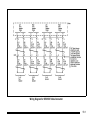
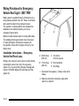
Wiring Provisions for Emergency
Vehicle Roof Light - SEO TRW
Battery power is supplied through a 30 amp fuse to a
wiring harness located in the roof. Power is controlled
with a switch located in the overhead console.
The customer or vehicle upfitter must complete the
installation to an added accessory such as an
emergency beacon lamp.
Maximum rated electrical load is 21 amps (250 watts).
The added electrical requirements must not exceed
21 amps (250 watts). Running the accessory for
long periods of time with the engine off may run the
battery down.
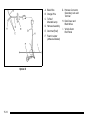
Installation Instructions — Emergency
Vehicle Roof Panel Lamp
Wiring to the accessory can be done by either directly
connecting the wire in the roof to the accessory
(Option A) or by using Wiring Harness Package part
number 12150250 obtained from GM Service Parts
(Option B).
A. 25.39 inches
(645 mm)
C. 3.94 inches
(100 mm) square
B. 17.32 inches
(440 mm)
D. Roof Centerline
E. Roof Edge
1. Disconnect the negative (−) battery cable at the
battery.
2. Make the electrical connections using either
option A or option B.
15-12
Notice: Pulling the wiring harness through a panel
hole that has sharp edges may cause damage to the
wire and/or wire insulation. Remove sharp edges
from the panel hole before pulling the wire
through it.
Option A: Roof Wires Directly to Accessory
1. Drill a 3/8 inch to 1/2 inch (10 to 13 mm) hole in
the outer roof panel in the area shown in the
illustration. The hole should only go through the
outer panel. Remove all sharp edges from the
drilled hole.
5. As one person watches the roof hole from the
outside for the end of the harness, a second
person from the inside of the vehicle should snake
the harness toward the hole.
6. Pull out the wiring harness being careful to avoid
scraping the insulation on the edge of the hole.
7. Extend the wiring harness to the accessory.
8. Connect the dark green wire to the accessory hot
terminal.
9. Connect the black wire to the accessory ground
terminal.
2. Remove the inside overhead console access
panel/lamp lenses.
10. Cover the hole in the roof with a durable sealant
such as silicone rubber sealer.
3. The accessory harness is coil tied to the
passenger's side of the vehicle at the console
inner bracket.
11. Reinstall the overhead console access panel/lamp
lenses.
4. Cut the tape holding the harness coil.
15-13
Option B: Use Wiring Harness
Package 12150250. Obtain from
GM Service Parts through the
GM Dealership
1. Drill a 1.25 inch (32 mm) hole in the outer roof
panel in the area shown in the illustration. The hole
should only go through the outer panel. Remove all
sharp edges from the drilled hole.
2. Remove the inside overhead console access
panel/lamp lenses.
3. The accessory harness is coil tied to the
passenger's side of the vehicle at the console
inner bracket.
4. Cut the tape holding the harness coil.
5. As one person watches the roof hole from the
outside for the end of the harness, a second
person from the inside of the vehicle should snake
the harness toward the hole.
6. Pull out the wiring harness being careful to avoid
scraping the insulation on the edge of the hole.
15-14
7. Cut the wire to length. Install terminals to wire ends
and insert into the connector. The dark green wire
goes to cavity A and the black wire in cavity B.
Push in the secondary lock to retain the wires.
8. Attach the harness assembly from the package to
the accessory. Cover with the supplied conduit for
added protection. Connect the orange wire to the
accessory hot terminal and the black wire to the
ground.
9. Complete the connection from the roof harness to
the extension harness. Cover the mated connector
with the supplied foam. Push the foam covered
connection and excess wire through the roof
panel hole.
10. Reinstall the overhead console access panel/lamp
lenses.
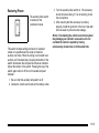
Restoring Power
The auxiliary lamp switch
is located on the
overhead console.
This switch includes wiring provisions for a dealer/
retailer or a qualified service center to install an
auxiliary roof lamp. When the wiring is connected to an
auxiliary roof mounted lamp, pressing the bottom of the
switch will activate the lamp and illuminate an indicator
light at the bottom of the switch. Pressing the top of the
switch again will turn off the roof mounted lamp and
indicator.
3. Turn the auxiliary lamp switch on. The accessory
should now be working. If it is not working, check
the connections.
4. After ensuring that the accessory is working
properly, install the grommet in the hole. Seal with
silicone sealer to prevent water leakage.
Notice: Overloading the vehicle's electrical system
may damage your vehicle's accessories. Do not
overload the vehicle's system by having
unnecessary accessories on at the same time.
1. Be sure that the auxiliary lamp switch is off.
2. Vacate the vehicle and reconnect the battery cable.
15-15
A. Black Wire
B. Orange Wire
C. To Roof
Mounted Lamp
D. Harness Assembly
E. Grommet (Roof)
F. Foam Insulator
(Adhesive‐Backed)
Option B
15-16
G. Harness Connector,
Secondary Lock and
Terminal
H. Dark Green and
Black Wires
I. Vehicle Outer
Roof Panel
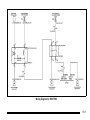
Wiring Diagram for SEO TRW
15-17
Maintenance
The emergency roof light circuit is fed from the fuse
labeled Sunroof located in the underhood electrical
center. Always replace the fuse with a 30 amp
mini-fuse.
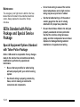
SEOs Standard with Police
Package and Special Service
Package
Special Equipment Options Standard
with Tahoe Police Package
Notice: GM cannot be responsible for any changes
made to the vehicle. Have all electrical and body
modifications performed by experienced
technicians.
.
Be sure that any modified or added wiring
will work properly with your vehicle's wiring
system.
.
See that all wiring is properly protected by
fuses, and not causing an overload to
connectors and components.
15-18
.
Do not route wiring in areas of the vehicle
where temperatures can be high or where
wiring may be cut, pinched or rubbed.
.
See that all added wiring is of the same or
smaller gauge than the wire it is being
attached to for proper fuse protection.
.
Be sure that all holes drilled in the body are
properly sealed and corrosion protected.
See that the vehicle's wiring harnesses,
piping and other components have not been
displaced or damaged during customer
installations of equipment and wiring.
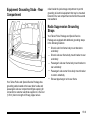
Equipment Grounding Studs - Rear
Compartment
coiled inside the jack storage compartment to permit
grounding of electrical equipment that may be mounted
forward in the rear compartment and behind the second
row seatback.
Radio Suppression Grounding
Straps
Your Tahoe Police Package and Special Service
Package are equipped with additional grounding straps
in the following locations:
.
Driver's side front frame body mount bracket to
underbody
.
Driver's side rear frame body mount bracket to rear
underbody
.
Passenger's side rear frame body mount bracket to
rear underbody
.
Passenger's side center frame body mount bracket
to center underbody
.
Exhaust pipe hanger rod to rear frame
Your Tahoe Police and Special Service Package has
grounding studs located at the lower driver's side and
passenger's side rear compartment liftgate opening for
connection to customer electrical equipment. A five foot
(1.83 m) blunt cut length of #8 awg copper wire is
15-19
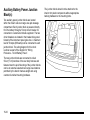
Auxiliary Battery Power Junction
Block(s)
Two auxiliary power junction blocks are located
within the driver's side rear cargo area jack stowage
compartment. Each junction block is powered directly
from the battery through a 50 amp circuit breaker for
connection to customer‐furnished equipment. The two
circuit breakers are located in the breaker/relay panel
forward of the instrument panel glove box. A maximum
load of 50 amps (600 watts) can be connected to each
junction block. The wiring diagram for this circuit
is shown as part of the diagram for “Wiring
Provisions ‐ 12 Volt Battery Power”.
The two junction blocks are connected to coiled
5 foot (1.5 m) branches of the rear body harness and
fastened near the jack. Mounting of the junction blocks
can be at customer‐selected rear cargo area locations
permitted by the branch harness length and using
customer‐furnished mounting hardware.
15-20
The junction blocks should not be attached to the
interior trim plastic components without appropriate
backing hardware to the mounting bolts.
To connect the customer-furnished equipment at the
junction blocks, use the following steps:
1. Disconnect the negative (−) battery cable.
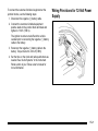
Wiring Provisions for 12-Volt Power
Supply
2. Connect the customer-furnished equipment
positive leads to the junction block terminals and
tighten to 11 lb ft (15 N·m).
The ignition must be turned off and the vehicle
vacated prior to connecting the negative (−) battery
cable to the battery.
3. Reconnect the negative (−) battery cable to the
battery. Torque the bolt to 3.6 lb‐ft (5 Y).
4. Set the time on the clock and radio pushbuttons as
needed. See “Audio Systems” in the Instrument
Panel section of your Tahoe owner's manual for
more information.
15-21
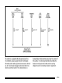
Wiring Provisions ‐ 12‐Volt Battery Power
15-22
The vehicle is equipped with wiring provisions for a
12-volt battery power supply. Refer to the following
information when adding electrical accessories that will
use the 12-volt power supply feeds connected to the
vehicle's electrical system. The wiring harness is
located below the instrument panel near the center of
the vehicle. The following information describes the
breaker and relay location and provides a wiring
diagram to aid in connecting customer equipment.
15-23
Electrical Connections
Notice: Before modifying or adding any wiring,
be sure that it will work properly with your
vehicle's wiring system. Because there are so
many modifications that can be made for many
different bodies and accessories, GM cannot take
responsibility for any changes made. Such changes
may not be covered by your GM Warranty. Have the
work done by an experienced electrical technician.
All wiring must be properly protected by fuses, etc.
and must be routed properly so that it will not be
cut, pinched or rubbed by other parts of the vehicle.
Do not route wiring in areas where it will be very
hot. Be sure not to overload the vehicle's wiring,
connectors and components. All added wire must
be at least the same size as the wire being attached
to for proper fuse protection.
Installation Instructions — 12‐Volt
Accessory Power Supply
1. Disconnect the negative (−) battery cable at the
battery. The negative (−) battery cable must be
disconnected before the positive wiring lead is
connected to the power accessory.
2. Locate the power supply harnesses, one under the
instrument panel near the center of the vehicle,
and one within the driver side rear cargo area jack
stowage compartment.
3. Prepare the wires that are to be used to connect
the power accessory. Do not remove the unused
wires. Tape unused wires back in their original
position under the instrument panel.
4. Complete the wiring installation of the customer
added accessory with additional wire required for
the specific electrical accessory power connection.
The wire gauge, 12 gauge (3.0 mm²), should be
the same as the wiring of the installed harness.
5. The ignition must be turned to OFF prior to
attaching the cables to the battery, or serious
damage to the Body Control Module (BCM) may
result.
The windshield wiper switch and the radio must be
turned off before attaching cables to the battery.
15-24
6. Reconnect the negative (−) battery cable to the
battery. Torque the bolt to 3.6 lb-ft. (5 Y).
7. Reset the clock time and radio pushbuttons as
desired.
The 12‐volt battery power is supplied through two
underhood mega fuses, one 125 amp and one 60 amp.
This underhood power is fed to the breaker/relay center
via a harness that passes through the driver side front
of the dash, and routes across the instrument panel to a
position forward of the glove box. The breaker/relay
center is mounted to the instrument panel structure
forward of the glove box. The center includes a
plastic bracket, two relays, two 30 amp breakers and
three 50 amp mega circuit breakers.
Two 30 amp breakers supply power from the underhood
60 amp mega fuse through the contacts of the control
relays to 12 gauge (3.0 mm²) blunt cut wires. These
two blunt cut leads are part of wire coil under the
instrument panel near the center of the vehicle.
Each relay is operated by a 20 gauge (0.5 mm²) blunt
cut, light or dark blue control lead included in the 4 foot
(122 cm) loop of wire coiled under the instrument panel.
Three 50 amp mega circuit breakers, protected by
three fusible links, supply power directly from the
underhood 125 amp mega fuse through three, 10‐gauge
wires (5.0 mm²) wires. Two of the wires are routed
through the body harness to buss junction blocks in the
left rear of the cargo area and secured near the jack
and tools. This 4 foot (122 cm) of coiled wires can be
accessed by removing the cup holder on the top of the
trim panel. The third 10‐gauge (5 mm²) wire is a blunt
cut lead which is part of the 4 foot (122 cm) loop of wire
coiled under the instrument panel near the center of the
vehicle.
An 8‐gauge (8 mm²) ground lead is also provided, and it
is located under the front passenger sill plate. It can be
accessed by removing the sill plate and pulling the loop
of wire at the front of the plate. The lead is 4 feet
(122 cm) long.
15-25
Blunt cut ignition controlled power and signal circuits
are also included in the wire coiled under the instrument
panel near the center of the vehicle. They include:
.
*A yellow, 20 gauge (0.5 mm²) circuit, Hot in
ACCESSORY, RUN or RAP (Retained Accessory
Power).
.
A pink, 20 gauge (0.5 mm²) circuit, Hot in START
and RUN. (7A maximum load)
.
*A yellow/black, 20 gauge (0.5 mm²) transmission
park signal. This circuit provides switched power
when the transmission is in P (Park) and the
engine is running. The circuit is at 0 volts when
the transmission is in any other position,
i.e., R (Reverse), N (Neutral), D (Drive) or
M (Manual). Note that the circuit is also at 12 volts
with the transmission in P (Park) and the ignition in
LOCK/OFF. To avoid the possibility of undesired
parasitic electrical load with the ignition in
LOCK/OFF it is suggested that the Park/Signal
circuit be isolated by routing it through the normally
open contact of a customer furnished ignition
controlled relay.
.
A dark green/white, 20 gauge (0.5 mm²) Vehicle
Speed Signal (VSS) provides 4,000 pulses
per mile.
*These two circuits share a 15 amp fuse.
(10 amp combined maximum load)
15-26
Servicing Relays and Fuses
Fuse/Relay Center
The following information tells how to access the
vehicle's relay and breaker center for checking and
replacing breakers.
The breaker and relay center is located behind and
above the instrument panel storage compartment.
Remove contents from the storage tray. Using the
tab at the back of the compartment, drop the tray down
gently toward the floor. It will hang from the hinge.
The breaker/relay center is located above the right
rear corner of the storage compartment. The bracket
is attached to the instrument panel structure with
two screws.
Replace a 30 amp circuit breaker with
GM Part No. 12182117 circuit breaker, or equivalent.
Replace a relay with a GM Part No. 12193604 relay,
or equivalent. Replace a 50 amp circuit breaker with a
GM Part No. 15319848 circuit breaker, or equivalent.
Enlarged View of the Fuse Block
A. Relays and Circuit
Breakers
C. Floor of the Vehicle
B. Front of the Vehicle
E. Tab
Reinstall the storage tray into the compartment by lifting
it into the instrument panel.
D. Glove Box
15-27
2 NOTES
15-28
A
D
Airbag Deployment Diagrams . . . . . . . . . . . . . . . . . . . . . . . .2-6
Airbag, Notices for Customer Installed Equipment . . .2-5
Airbags, Questions and Answers About Airbags
and Specialty Law Enforcement Vehicles . . . . . . . . . .2-2
Auxiliary Battery Power Junction Block(s) . . . . . . . . . 15-20
Driver Information Center (DIC) . . . . . . . . . . . . . . . . . . . . . .4-5
B
Battery
Dual System - SEO 6A6 . . . . . . . . . . . . . . . . . . . . . . . . . . . 6-2
C
Canadian Owners . . . . . . . . . . . . . . . . . . . . . . . . . . . . . . . . . . . . . ii
Capacities and Specifications . . . . . . . . . . . . . . . . . . . . . . . .6-3
E
Exterior Lamp Emergency Flashing
System - SEO 6J7 . . . . . . . . . . . . . . . . . . . . . . . . . . . . . . . 15-2
Exterior Lamps . . . . . . . . . . . . . . . . . . . . . . . . . . . . . . . . . . . . . .4-2
G
Gages
Speedometer . . . . . . . . . . . . . . . . . . . . . . . . . . . . . . . . . . . . . . 4-5
Grounding Studs, Equipment, Rear
Compartment . . . . . . . . . . . . . . . . . . . . . . . . . . . . . . . . . . . 15-19
Grounding Studs, Radio Suppression . . . . . . . . . . . . . 15-19
i-1
H
O
Headlamps
Exterior Lamps . . . . . . . . . . . . . . . . . . . . . . . . . . . . . . . . . . . . 4-2
Odometer . . . . . . . . . . . . . . . . . . . . . . . . . . . . . . . . . . . . . . . . . . . .4-5
Owners, Canadian . . . . . . . . . . . . . . . . . . . . . . . . . . . . . . . . . . . . . ii
I
Q
Inactive Rear Door Handles - SEO 6B2 . . . . . . . . . . . . 15-5
Inactive Rear Door Locks - SEO 6N6 . . . . . . . . . . . . . . 15-5
Inactive Rear Door Windows - SEO 6N5 . . . . . . . . . . . 15-5
Instrument Panel Cluster . . . . . . . . . . . . . . . . . . . . . . . . . . . .4-2
Questions and Answers About Airbags and
Specialty Law Enforcement Vehicles . . . . . . . . . . . . . . .2-2
L
Lamps
Exterior Lamp Emergency Flashing
System - SEO 6J7 . . . . . . . . . . . . . . . . . . . . . . . . . . . . . . 15-2
Lights
Exterior Lamps . . . . . . . . . . . . . . . . . . . . . . . . . . . . . . . . . . . . 4-2
Loading Your Vehicle . . . . . . . . . . . . . . . . . . . . . . . . . . . . . . . .5-2
i-2
R
Radio Suppression Grounding Studs . . . . . . . . . . . . . 15-19
Rear Compartment, Equipment Grounding
Studs . . . . . . . . . . . . . . . . . . . . . . . . . . . . . . . . . . . . . . . . . . . 15-19
Running the Vehicle While Parked . . . . . . . . . . . . . . . . . . .3-3
S
Safety Belts
Questions and Answers About Airbags and
Specialty Law Enforcement Vehicles . . . . . . . . . . . . . 2-2
SEO
6J3, Wiring Provisions for Vehicle Grille
Lamps, Flasher and Speaker/Siren . . . . . . . . . . . . . . 15-8
6J4, Wiring Provision for Horn/Siren Circuit . . . . . . . 15-6
6J7, Exterior Lamp Emergency Flashing
System . . . . . . . . . . . . . . . . . . . . . . . . . . . . . . . . . . . . . . . . . . 15-2
7X6, Spotlamp . . . . . . . . . . . . . . . . . . . . . . . . . . . . . . . . . . . . 15-5
7X7, Spotlamps . . . . . . . . . . . . . . . . . . . . . . . . . . . . . . . . . . 15-6
9L4, Wiring Provisions for 12-Volt Power
Supply . . . . . . . . . . . . . . . . . . . . . . . . . . . . . . . . . . . . . . . . .15-21
WX7, Wiring Provisions Front Speakers . . . . . . . . .15-10
Special Equipment Options
Standard with Tahoe Police Package . . . . . . . . . . . .15-18
Specific Cylinder Unit for Single Key - Random
Code System . . . . . . . . . . . . . . . . . . . . . . . . . . . . . . . . . . . . . .3-2
Specifications and Capacities . . . . . . . . . . . . . . . . . . . . . . . .6-3
Speedometer . . . . . . . . . . . . . . . . . . . . . . . . . . . . . . . . . . . . . . . .4-5
T
Tires . . . . . . . . . . . . . . . . . . . . . . . . . . . . . . . . . . . . . . . . . . . . . . . . .6-2
Pressure Monitor System . . . . . . . . . . . . . . . . . . . . . . . . . . 6-2
Towing
Trailer . . . . . . . . . . . . . . . . . . . . . . . . . . . . . . . . . . . . . . . . . . . . . 5-5
i-3
V
W
Vehicle
Loading . . . . . . . . . . . . . . . . . . . . . . . . . . . . . . . . . . . . . . . . . . . . 5-2
Running While Parked . . . . . . . . . . . . . . . . . . . . . . . . . . . . . 3-3
Wiring Provisions
12-Volt Power Supply - SEO 9L4 . . . . . . . . . . . . . . . .15-21
Emergency Vehicle Roof Light - SEO TRW . . . . . .15-12
Front Speakers - SEO WX7 . . . . . . . . . . . . . . . . . . . . .15-10
Horn/Siren Circuit - SEO 6J4 . . . . . . . . . . . . . . . . . . . . . 15-6
Vehicle Grille Lamps, Flasher and Speaker/
Siren - SEO 6J3 . . . . . . . . . . . . . . . . . . . . . . . . . . . . . . . . . 15-8
i-4