1
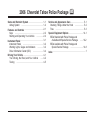
2006 Chevrolet Tahoe Police Package
Seats and Restraint System .............................
Airbag System ...........................................
Features and Controls .....................................
Keys
........................................................
Starting and Operating Your Vehicle
.............
Instrument Panel .............................................
Instrument Panel ........................................
Warning Lights, Gages and Indicators ...........
Driver Information Center (DIC) ....................
Driving Your Vehicle .......................................
Your Driving, the Road, and Your Vehicle
.....
Towing
.....................................................
1-1
1-2
2-1
2-2
2-4
3-1
3-2
3-2
3-4
4-1
4-2
4-5
M
Service and Appearance Care .......................... 5-1
Checking Things Under the Hood ................. 5-2
Tires
........................................................ 5-3
Special Equipment Options ............................ 14-1
SEOs Standard with Police Package and
Available with Special Service Package ...... 14-2
SEOs Available with Police Package and
Special Service Package ......................... 14-8
Index .................................................................1
Keep this manual in the vehicle, so it will be there if
it is needed. If the vehicle is sold, leave this manual in
the vehicle.
The Tahoe Police Package (SEO PPV) has been
designed for police work up to and including high-speed
emergency vehicle operations.
GENERAL MOTORS, GM, the GM Emblem,
CHEVROLET, the CHEVROLET Emblem, and the
name TAHOE are registered trademarks of General
Motors Corporation.
The information in this manual supplements the owner
manual. This manual includes the latest information
at the time it was printed. We reserve the right to make
changes after that time without notice.
Litho in U.S.A.
Part No. 15791157 A First Printing
ii
The Tahoe Special Service Package (SEO 5W4) is not
designed nor intended for use in high-speed emergency
vehicle operations.
Canadian Owners
A French language copy of this manual can be obtained
from your dealer or from:
Helm, Incorporated
P.O. Box 07130
Detroit, MI 48207
©
2005 General Motors Corporation. All Rights Reserved.
Section 1
Seats and Restraint System
Airbag System .................................................1-2
Questions and Answers About Airbags and
Specialty Law Enforcement Vehicles ..............1-2
1-1
Airbag System
Questions and Answers About
Airbags and Specialty Law
Enforcement Vehicles
Tahoe Police Package and Special
Service Package
Q: Can equipment such as radar devices, video
cameras and radio trees be mounted in a
specialty vehicle equipped with a right front
passenger’s frontal airbag?
A: Yes, but care must be taken to properly mount the
equipment outside of the airbag “deployment zone.”
1-2
Q: What is the airbag “deployment zone”?
A: The term “deployment zone” describes the space
an airbag takes up when fully inflated. Airbags
need room to work properly, and anything in the
“deployment zone” — such as improperly mounted
equipment — can greatly affect the performance
of the airbag.
{CAUTION:
Airbags inflate with great force, faster than the
blink of an eye. Equipment mounted too close
to an inflating airbag could break and become
a dangerous projectile in a crash, causing
injury to the vehicle’s occupants. Also, an
object too close to an inflating airbag could
prevent the airbag from operating properly.
If this ever happens, the airbag would not be
able to protect occupants the way it was
designed to. To help prevent injury and to
allow the airbag to perform as it was designed,
do not mount equipment inside the airbag
deployment zone.
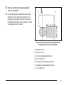
Q: How can I identify the airbag “deployment
zone” in my vehicle?
A: The following diagrams provide the approximate
dimensions of the “deployment zones” for your
specialty vehicle. Before doing any service work,
including the installation of any equipment, consult
the appropriate service manual.
Top View of Instrument Panel and Approximate
Deployment Area of the Airbag Zone
A.
B.
C.
D.
E.
F.
G.
Instrument Panel
Front of Vehicle
Driver’s Airbag Deployment Zone
30.7 in (780 mm)
Passenger’s Airbag Deployment Door
Passenger’s Airbag Deployment Zone
17.7 in (450 mm)
1-3
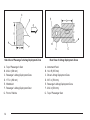
Side View of Passenger’s Airbag Deployment Zone
A.
B.
C.
D.
E.
F.
G.
1-4
Top of Passenger’s Seat
23.2 in (590 mm)
Passenger’s Airbag Deployment Zone
17.7 in (450 mm)
Windshield
Passenger’s Airbag Deployment Door
Front of Vehicle
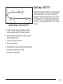
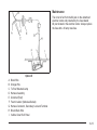
Rear View of Airbag Deployment Zones
A.
B.
C.
D.
E.
F.
G.
Instrument Panel
14 in R (355 mm)
Driver’s Airbag Deployment Zone
30.7 in (780 mm)
Passenger’s Airbag Deployment Zone
23.2 in (590 mm)
Top of Passenger Seat
Q: Is it possible to shield equipment so it does not
interfere with airbag deployment?
A: While shielding may protect certain equipment from
being damaged or dislodged, it may also negatively
affect how an airbag inflates. Therefore, we cannot
recommend the placement of any equipment in
the deployment zone, even when shielding.
Q: Can the installation of push bumpers on the
front end of the vehicle affect the deployment
of the airbag?
A: It is not likely that installing push bumpers will affect
sensing for the airbag as long as the vehicle
structure itself is not modified. GM is not aware of
any adverse effects from the many push bumpers
that have been installed on current model GM police
vehicles with airbags.
Q: Is there anything I might add to the front or
sides of the vehicle that could keep the
airbags from working properly?
A: Yes. If you add things that change your vehicle’s
frame, bumper system, front end or side sheet
metal or height, they may keep the airbag system
from working properly. Also, the airbag system may
not work properly if you relocate any of the airbag
sensors. If you have any questions about this,
you should contact Customer Assistance before you
modify your vehicle. The phone numbers and
addresses for Customer Assistance are in Step Two
of the Customer Satisfaction Procedures in the
owner’s manual. See “Customer Satisfaction
Procedure” in your owner’s manual Index.
1-5
✍ NOTES
1-6
Section 2
Features and Controls
Keys ...............................................................2-2
Specific Cylinder Unit for Single Key - Random
Code System ..............................................2-2
Starting and Operating Your Vehicle .................2-4
Running the Engine While Parked .....................2-4
2-1
Keys
Specific Cylinder Unit for
Single Key - Random Code System
Tahoe Police Package and Special
Service Package
If your vehicles are equipped with one of these options,
the entire fleet of vehicle locks can be operated with
one key.
• SEO 6E2-Specific Fleet Key Code
• SEO 6E8-Specific Fleet Key Code
Your vehicle will be equipped with a standard production
random key code if one of the optional fleet codes
was not ordered.
For specific key code information, contact your dealer.
Your vehicles will be equipped with a key cylinder
in the ignition lock and the driver’s door only.
Remote keyless entry (RKE) is a standard feature
and operates all other doors and the rear liftgate.
2-2
Six additional RKE transmitters may have been ordered
with your vehicle. See your dealer for additional
information regarding availability of more RKE units for
your vehicle.
Transmitter Programming - SEO AMF
Do not operate or program the transmitters in the vicinity
of other vehicles that are in the keyless entry program
mode. This prevents the programming of the transmitters
to the incorrect vehicle.
Up to four transmitters may be programmed to the
passenger door module (PDM). Each programmed
transmitter is given a position of #1-#4 in the PDM
memory.
All transmitters which are to be recognized by the
PDM must be programmed in a single programming
sequence. When using this programming method,
all previously programmed transmitters will be erased
upon the receipt of the programming signal from the
first transmitter.
The order in which the transmitters are programmed
will determine its numbering position within the
PDM memory. The first transmitter programmed will be
transmitter #1, and the second transmitter programmed
will be transmitter #2. The number stamped on the
transmitter case is for reference only. #2 can be
programmed as #1, or vice versa. Additional
unnumbered transmitters are also available.
The method for programming transmitters is listed in the
following steps.
1. Close all of the vehicle doors.
2. Insert the ignition key into the ignition lock cylinder.
3. Press and hold the door unlock switch.
5. Release the door unlock switch. The doors will lock
and unlock to confirm the program mode.
6. Press and hold the lock button and the unlock
button simultaneously on one transmitter. After a
delay of about 15 seconds, the doors will lock
and unlock to confirm the programming of that
transmitter.
7. Repeat the previous step to program up to
four transmitters.
8. Turn the ignition switch to RUN in order to exit the
keyless entry transmitter programming mode.
9. Operate the transmitter functions in order to verify
correct system operation.
4. While holding the door lock switch in the unlock
position, cycle the ignition on, off, on, off.
2-3
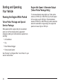
Starting and Operating
Your Vehicle
Running the Engine While Parked
Tahoe Police Package and Special
Service Package
While parked with the engine idling for an extended
period, turn off the following factory equipment if
emergency lighting and communication equipment are
operating:
•
•
•
•
Air Conditioner
Fan
Rear Window Defogger
Factory Audio System
See “Running Your Engine While You’re Parked” in your
owner’s manual Index.
2-4
Engine Idle Speed - Alternator Output
(Tahoe Police Package Only)
To increase alternator output while your Tahoe police
vehicle is in PARK (P) or NEUTRAL (N), the idle speed
for the engine is set for 800 rpm. If the transmission
remains in PARK (P) or NEUTRAL (N), and the electrical
load on the alternator is large enough, the engine idle
speed can rise as high as 1000 rpm.
Section 3
Instrument Panel
Instrument Panel ..............................................3-2
Exterior Lamps ...............................................3-2
Warning Lights, Gages and Indicators ...............3-2
Instrument Panel Cluster .................................3-2
Speedometer and Odometer ............................3-4
Driver Information Center (DIC) .........................3-4
3-1
Instrument Panel
Exterior Lamps
Tahoe Police Package and Special
Service Package
The following exterior lighting features apply to vehicles
first sold in the United States. The DRL and AHS must
always remain fully functional for vehicles first sold
in Canada.
Your vehicle is equipped with Daytime Running Lamps
(DRL) and an Automated Headlamp System (AHS).
The DRL and AHS can be turned off with the headlamp
switch when the transmission is in PARK (P) and the
engine is at idle. If the engine is not turned off, the DRL
and AHS will remain off when the transmission is
placed in gear. The vehicle may be driven with the
lamps off for one ignition cycle.
For vehicles first sold in Canada, the DRL and AHS
can be turned off if the park brake is pressed and the
transmission remains in PARK (P) before the engine
is started. To turn off DRL or AHS in Canadian Tahoe
Police Package vehicles, your transmission must be
in PARK (P) and the parking brake must be set.
See your owner’s manual for more information.
3-2
Your vehicle may have been built with SEO 9G8,
DRL and AHS disable. This feature turns off DRL and
AHS and requires manual control of the exterior lighting.
See your dealer to restore the DRL and AHS to
normal operation.
Warning Lights, Gages and
Indicators
Instrument Panel Cluster
Tahoe Police Package and Special
Service Package
The Tahoe Police Package instrument panel cluster is
shown. The Tahoe Special Service Package instrument
panel cluster is similar, except that the word “certified”
is not displayed, the maximum speed displayed is lower
and additional indicators may be present. See “Warning
Lights, Gages and Indicators” in the Index of your
Tahoe owner’s manual for more information.
Tahoe Police Package - SEO PPV (United States version shown, Canada similar)
3-3
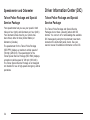
Speedometer and Odometer
Driver Information Center (DIC)
Tahoe Police Package and Special
Service Package
Tahoe Police Package and Special
Service Package
Your speedometer lets you see your speed in both
miles per hour (mph) and kilometers per hour (km/h).
Your odometer shows how far your vehicle has
been driven, either in miles (United States) or
kilometers (Canada).
The Tahoe Police Package and Special Service
Packages do not have a steering wheel with DIC
buttons. You can turn off or acknowledge the available
DIC messages by using the trip odometer reset stem
located on the instrument panel cluster. See your
owner’s manual for additional information on the DIC.
The speedometer for the Tahoe Police Package
(SEO PPV) displays a maximum vehicle speed of
140 mph (225 km/h). The speedometer for the
Tahoe Special Service Package (SEO 5W4) displays
a maximum vehicle speed of 120 mph (193 km/h).
The Tahoe Special Service Package is not designed
nor intended for use in high-speed emergency vehicle
operations.
3-4
Section 4
Driving Your Vehicle
Your Driving, the Road, and Your Vehicle ..........4-2
Loading Your Vehicle ......................................4-2
Towing ............................................................4-5
Towing a Trailer .............................................4-5
4-1
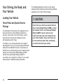
Your Driving, the Road, and
Your Vehicle
Loading Your Vehicle
Tahoe Police and Special Service
Package
The information in this section of the supplement is for
those who intend to install additional equipment to
the police vehicle after it has left the factory, and for
those who will be driving and loading the vehicle
with passengers and/or cargo.
Two labels on your vehicle show how much weight it
was designed to carry, the Tire and Loading Information
label and the Certification/Tire label. These labels are
attached to your vehicle and give you the maximum load
capacity, the Gross Vehicle Weight Rating (GVWR)
and the Gross Axle Weight Rating (GAWR) for
your vehicle. See “Loading Your Vehicle” in your owner
manual Index for additional loading information.
4-2
The following guidelines can help you with proper
loading and load distribution when installing additional
equipment on the Tahoe Police Package.
{CAUTION:
Do not load your vehicle any heavier than the
Gross Vehicle Weight Rating (GVWR), or either
the maximum front or rear Gross Axle Weight
Rating (GAWR). If you do, parts on your
vehicle can break, and it can change the way
your vehicle handles. These could cause you
to lose control and crash. Also, overloading
can shorten the life of your vehicle.
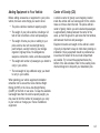
Adding Equipment to Your Vehicle
Center of Gravity (CG)
Before adding accessories or equipment to your police
vehicle, there are some things you need to know
A vehicle’s center of gravity is an imaginary location
inside the vehicle and is a balance point for the vehicle
mass as it moves down the road. The police vehicle’s
center of gravity, before you add a load and passengers,
is approximately midway between the center of the
axles, up from the ground to just below the front window,
and between the driver and passenger.
• The police vehicle’s maximum capacity weight.
• The weight of your police vehicle, including a full
tank of fuel but without a driver and passengers.
• The weight of items you plan on adding to your
police vehicle, like roof mounted light bar(s),
push bumpers, security barrier(s), rear storage
organizer, highway flares, fire extinguishers,
weapons, ammunition, radios, and video equipment.
• The weight and number of passengers you intend to
carry in your vehicle.
• The total weight of any additional cargo you intend
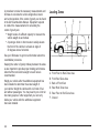
Equipment location and weight on the vehicle’s center
of gravity is important to keep in mind when planning an
installation. Heavy equipment should be positioned as
low and as far forward in the rear load compartment
as possible. Try to mount the equipment below the
bottom of the side windows. Refer to the Loading Zone
chart and diagram to help with your installation plan.
to carry in your vehicle.
When planning your vehicle equipment installation
remember not to exceed the Gross Vehicle Weight
Rating (GVWR) or the Gross Axle Weight Rating
(GAWR) of the front or rear axles. To keep the available
load weight less than the vehicle capacity weight, you
may need to limit the number of passengers you carry
in your vehicle or change your choice of additional
equipment.
4-3
A procedure to make the necessary measurements and
formulas to calculate the vehicle longitudinal, lateral
and vertical position of the center of gravity can be found
in the GM Coachbuilders Manual. Equipment required
to conduct the measurements for calculating the
center of gravity are:
• Weight scales of sufficient capacity to measure the
vehicle weight at each wheel.
• A post-type hoist or other means to safely elevate
the front of the vehicle to at least an angle of
20 degrees above horizontal.
Loading Zones
See your GM dealer to get more information about this
coachbuilder procedure.
Keeping the center of gravity midway between the axles
is also important to provide proper braking performance.
About half the total vehicle weight on each axle is
recommended.
Weigh your vehicle after the additional equipment has
been installed to determine the actual weight of
your vehicle. Weigh the vehicle with a full tank of fuel
and without passengers. You may need to put a limit on
how many people or other equipment you can carry
inside your vehicle after the additional equipment
has been installed.
4-4
A.
B.
C.
D.
E.
F.
Front Floor to Roof Zone Area
Front Roof Zone Area
Back of Front Door
Rear Roof Zone Area
Rear Floor to Roof Zone Area
Ground
Towing
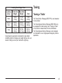
Loading Zone Weight Chart
Loading
Zones
Front Axle
Weight
Rear Axle
Weight
Total
Roof
29 lbs
(13 kg)
41 lbs
(19 kg)
70 lbs
(32 kg)
Floor to
Roof
108 lbs.
(49 kg)
426 lbs.
(193 kg)
534 lbs.
(242 kg)
Total
137 lbs
(62 kg)
465 lbs
(211 kg)
604 lbs
(274 kg)
Using heavier suspension components to get added
durability might not change your weight ratings. Ask your
dealer to help you load your vehicle the right way.
Towing a Trailer
The Tahoe Police Package (SEO PPV) is not intended
to tow a trailer.
The Tahoe Special Service Package (SEO 5W4) can
be equipped for trailer towing. See “Towing a Trailer”
in the owner’s manual Index for more information.
The Tahoe Special Service Package is not designed
nor intended for use in high-speed emergency vehicle
operations.
4-5
✍ NOTES
4-6
Section 5
Service and Appearance Care
Checking Things Under the Hood .....................5-2
Brakes ..........................................................5-2
Dual Battery System - SEO 8Y9 .......................5-2
Tires ...............................................................5-3
Tire Pressure Monitor System ..........................5-3
5-1
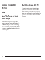
Checking Things Under
the Hood
Brakes
Tahoe Police Package and Special
Service Packages
All Tahoe Police Packages are equipped with a
hydraulic brake booster system called Hydroboost™.
The Hydroboost™ system uses the power steering
pump to create braking assist pressure. See “Brakes”
in your owner manual index for additional information
on the brake system.
5-2
Dual Battery System - SEO 8Y9
Your vehicle may be equipped with a dual battery
system. The two batteries are connected so that
both supply battery power to the vehicle at the same
time — they are connected in parallel. See “Battery” in
your owner’s manual Index for additional information
on batteries.
Tires
Tahoe Police and Special Service
Packages
The Tahoe Police Package (SEO PPV) has
P255/70R16 BW, H speed-rated tires. The Special
Service Package (SEO 5W4) has LT245/75R16 WOL, S
speed-rated tires. The Special Service Package is not
designed nor intended for use in high-speed emergency
vehicle operations.
Wheels
Metal hub caps are standard with SEO PPV. These caps
are bolted to the wheels and do not require removal
when rotating or removing the wheels. Loosening or
tightening the decorative cap nuts can be done with
the hub caps in place.
Tire Pressure Monitor System
The Tahoe Police and Special Service Packages are
equipped with a Tire Pressure Monitor (TPM) system.
Sensors are mounted on each tire and wheel assembly.
Only the Tahoe Police Package (SEO PPV) has a
TPM sensor in the full-size spare tire and wheel
assembly. The TPM system will not monitor or display
the spare tire’s air pressure until it is installed onto
one of the four tire/wheel positions on your vehicle.
Once installed, the spare tire’s sensor code must
be matched its new tire/wheel position on your vehicle.
See “Tire Pressure Monitor System” in your owner
manual Index for information about the TPM system.
5-3
✍ NOTES
5-4
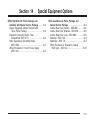
Section 14
Special Equipment Options
SEOs Standard with Police Package and
Available with Special Service Package ........14-2
Special Equipment Options Standard with
Tahoe Police Package ...............................14-2
Equipment Grounding Studs - Rear
Compartment (SEO UT7) ............................14-2
Radio Suppression Grounding Straps
(SEO UN9) ...............................................14-3
Wiring Provisions for 12-Volt Power Supply
(SEO 9L4) ................................................14-3
SEOs Available with Police Package and
Special Service Package ..............................14-8
Inactive Rear Door Handles - SEO 6B2 ...........14-8
Inactive Rear Door Windows - SEO 6N5 ..........14-8
Inactive Rear Door Locks - SEO 6N6 ..............14-8
Spotlamp - SEO 7X6 ....................................14-8
Spotlamps - SEO 7X7 ...................................14-9
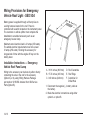
Wiring Provisions for Emergency Vehicle
Roof Light - SEO 5G4 ..............................14-10
14-1
SEOs Standard with Police
Package and Available
with Special Service Package
Special Equipment Options
Standard with Tahoe Police Package
Notice: GM cannot be responsible for any changes
made to the vehicle. Have all electrical and body
modifications performed by experienced
technicians.
• Be sure that any modified or added wiring will
work properly with your vehicle’s wiring system.
• See that all wiring is properly protected by fuses,
and not causing an overload to connectors and
components.
• Do not route wiring in areas of the vehicle where
temperatures can be high or where wiring may be
cut, pinched or rubbed.
14-2
• See that all added wiring is of the same or
smaller gauge than the wire it is being attached
to for proper fuse protection.
• Be sure that all holes drilled in the body are
properly sealed and corrosion protected.
See that the vehicle’s wiring harnesses, piping
and other components have not been displaced
or damaged during customer installations of
equipment and wiring.
Equipment Grounding Studs - Rear
Compartment (SEO UT7)
Your Tahoe Police Package has grounding studs
located at the lower driver’s side and passenger’s side
rear compartment liftgate opening for connection to
customer electrical equipment. A five foot (1.83 m) blunt
cut length of #8 awg copper wire is coiled inside the
jack storage compartment to permit grounding of
electrical equipment that may be mounted forward in the
rear compartment and behind the second row seatback.
These grounding studs may have been ordered for
your Tahoe Special Service Package.
Radio Suppression Grounding
Straps (SEO UN9)
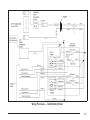
Wiring Provisions for 12-Volt
Power Supply (SEO 9L4)
Your Tahoe Police Package is equipped with additional
grounding straps in the following locations:
Your vehicle is equipped with wiring provisions for a
12-volt battery power supply. Refer to the following
information when adding electrical accessories that will
use the 12-volt power supply feeds connected to
your vehicle’s electrical system. The wiring harness is
located in front of the glove compartment. The following
information describes the fuse location and provides
a wiring diagram to aid in connecting customer
equipment. This wiring provision may have been
ordered for your Tahoe Special Service Package.
• Driver’s side front frame body mount bracket to
underbody
• Driver’s side rear frame body mount bracket to rear
underbody
• Passenger’s side rear frame body mount bracket to
rear underbody
• Passenger’s side center frame body mount bracket
to center underbody
• Exhaust pipe hanger rod to rear frame
These grounding straps may have been ordered for
your Tahoe Special Service Package.
14-3
Electrical Connections
Notice: Before modifying or adding any wiring,
be sure that it will work properly with your
vehicle’s wiring system. Because there are so
many modifications that can be made for many
different bodies and accessories, GM cannot take
responsibility for any changes made. Such changes
may not be covered by your GM Warranty. Have the
work done by an experienced electrical technician.
All wiring must be properly protected by fuses, etc.
and must be routed properly so that it will not be
cut, pinched or rubbed by other parts of the vehicle.
Do not route wiring in areas where it will be very
hot. Be sure not to overload the vehicle’s wiring,
connectors and components. All added wire must be
at least the same size as the wire being attached
to for proper fuse protection.
Installation Instructions — 12-Volt
Accessory Power Supply
1. Disconnect the negative (−) battery cable at the
battery. The negative (−) battery cable must be
disconnected before the positive wiring lead
is connected to the power accessory.
2. Locate the power supply harness under the
instrument panel near the passenger’s side of the
vehicle. The wire bundle consists of the pink
ignition (IGN), orange battery (BAT) and black
negative (NEG) wire feeds.
3. Remove the tape to release the wire bundles from
the power supply harness.
4. Remove the 40 amp MegaFuse that is taped to the
wire bundle. Set aside for installation, after
equipment wiring is complete.
5. Prepare the wires that are to be used to connect
the power accessory. Do not remove the unused
wires. Tape unused wires back in their original
position under the instrument panel.
6. Complete the wiring installation of the customer
added accessory with additional wire required for
the specific electrical accessory power connection.
The wire gauge, 12 gauge (3.0 mm), should be
the same as the wiring of the installed harness.
14-4
7. The ignition must be turned to LOCK or
ACCESSORY prior to attaching the cables to the
battery, or serious damage to the Vehicle Control
Module (VCM) may result.
The windshield wiper switch and the radio must be
turned off before attaching cables to the battery.
8. Disconnect the positive (+) battery cable at the
underhood power distribution center. Remove
the nut from the 8 mm stud (see illustration).
9. Install the 40 amp MegaFuse (from Step 4) in the
front holder on the underhood power distribution
center over the stud. Reinstall the positive (+)
battery cable with the mounting screw through the
MegaFuse terminal. Replace the 8 mm nut on
the stud. Torque both the nut and screw to
1.3-2.7 lb.-ft (6-12 Y).
10. Reconnect the negative (−) battery cable to the
battery. Torque the bolt to 12.5 lb-ft. (17 Y).
11. Reset the clock time and radio pushbuttons as
desired.
Underhood Power Distribution Center
The IGN A and IGN B connections have voltage
supplied and are hot when the ignition is turned to
ACCESSORY or RUN (pink color wire).
The BAT A and BAT B connections have voltage
supplied and are hot at all times (orange color wire).
The combined electrical load of IGN A and BAT A
must not exceed 21 amps (250 watts). Additionally, the
combined electrical load of IGN B and BAT B must not
exceed 21 amps (250 watts). The combined electrical
load of all circuits must not exceed 28 amps (340 watts).
14-5
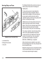
Servicing Relays and Fuses
The following information tells you how to access your
vehicle’s relay and fuse center for checking and
replacing fuses.
The fuse and relay center is located behind the
instrument panel storage compartment. Remove
contents from the storage tray. Push the right end of
the tray inward to allow the stop tab to clear the
compartment opening. Set the tray down gently toward
the floor. It will hang from the hinge.
Additional access to the relay and fuse center can be
gained by removing the center from the mounting
bracket. Lift the lock tab on the bottom away from the
bracket, then slide the center down the bracket
about 0.39 inches (10 mm) until it can be lifted away.
Exploded View of Instrument Panel
A. Instrument Panel
B. Relay and Fuse Center
C. Stop Tab
Then, using a screwdriver, remove the relay and fuse
center cover by lightly expanding the spring clips
on each side of the cover. Replace the 30 amp mini
fuse with a 30 amp mini fuse. Use a fuse puller if
your vehicle has one. Replace a relay with a
GM Part No. 12088592 relay, or equivalent.
After servicing the center, reinstall the relay center to
the bracket. Engage the D slots, then push upward until
the lock tab drops in place.
Reinstall the storage tray into the compartment by lifting
it into the instrument panel. Push in on the right side
to let the stop tab pass through the opening.
14-6
Wiring Provisions — 12-Volt Battery Power
14-7
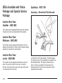
SEOs Available with Police
Package and Special Service
Package
Spotlamp - SEO 7X6
Spotlamps - Windshield Pillar Mounted
Inactive Rear Door
Handles - SEO 6B2
Your vehicle may be equipped with inactive door handles.
The rear doors can only be opened from the outside.
Inactive Rear Door
Windows - SEO 6N5
Your vehicle may be equipped with inactive rear door
window control switches. Only the driver’s power window
switches can operate the rear windows.
Inactive Rear Door
Locks - SEO 6N6
Your vehicle may be equipped with inactive rear door
locks. The rear door locks do not lock or unlock at
the door. Only the driver’s power door lock switch locks
or unlocks the rear door locks.
14-8
A Unity Series 330, high intensity, 100 watt halogen
(H3 bulb) six inch (15 cm) spotlamp is mounted in the
left windshield pillar. The lamp is protected by an
inline 15 amp fuse located in the left end of the
instrument panel. See the service manual for lamp
replacement procedures.
Spotlamps - SEO 7X7
Spotlamp Harness - SEO 7X6, SEO 7X7
Spotlamps are mounted in the driver’s and passenger’s
side windshield pillars. The lamps are protected by
separate 15 amp fuses located on the driver’s side of
the instrument panel. For spotlamp bulb replacement
procedures, see the appropriate section of the service
manual.
A. To INFO 12-way connector terminal D in driver’s
side convenience center left of steering column
B. Inline fuse holder with 15-amp mini fuses in driver’s
side of instrument panel
C. Connector at driver’s side pillar
D. Driver’s side spotlamp
E. Fuseholders in driver’s side end of instrument panel
F. Connector at passenger’s side pillar
G. Passenger’s side spotlamp
14-9
Wiring Provisions for Emergency
Vehicle Roof Light - SEO 5G4
Battery power is supplied through a 30 amp fuse to
a wiring harness located in the roof. Power is
controlled with a switch located on the instrument panel.
The customer or vehicle upfitter must complete the
installation to an added accessory such as an
emergency beacon lamp.
Maximum rated electrical load is 21 amps (250 watts).
The added electrical requirements must not exceed
21 amps (250 watts). Running the accessory for
long periods of time with the engine off may run the
battery down.
Installation Instructions — Emergency
Vehicle Roof Panel Lamp
Wiring to the accessory can be done by either directly
connecting the wire in the roof to the accessory
(Option A) or by using Wiring Harness Package
part number 12150250 obtained from GM Service
Parts (Option B).
14-10
A. 31.81 inches (808 mm)
B. 17.72 inches (450 mm)
C. 9.69 inches (246 mm)
D. Roof Centerline
E. Roof Edge
F. Centerline for
Drilled Hole
1. Disconnect the negative (−) battery cable at
the battery.
2. Make the electrical connections using either
option A or option B.
Notice: Pulling the wiring harness through a panel
hole that has sharp edges may cause damage to the
wire and/or wire insulation. Remove sharp edges
from the panel hole before pulling the wire through it.
Option A: Roof Wires Directly to Accessory
1. Drill a 3/8 inch to 1/2 inch (10 to 13 mm) hole in the
outer roof panel in the area shown in the illustration.
The hole should only go through the outer panel.
Remove all sharp edges from the drilled hole.
2. Pull out the wiring harness being careful to avoid
scraping the insulation on the edge of the hole.
3. Extend the wiring harness to the accessory.
4. Connect the brown wire to the accessory hot
terminal.
5. Connect the black wire to the accessory ground
terminal.
6. Cover the hole in the roof with a durable sealant
such as silicone rubber sealer.
Option B: Use Wiring Harness Package
12150250. Obtain from GM Service
Parts through the GM Dealership
1. Drill a 1.25 inch (32 mm) hole in the outer roof
panel in the area shown. The hole should only
go through the outer panel. Remove all sharp edges
from the drilled hole.
2. Pull out the wiring harness being careful to avoid
scraping the insulation on the edge of the hole.
3. Cut the wire to length. Install terminals to wire ends
and insert into the connector. The brown wire goes
in cavity A and the black wire in cavity B. Push in
the secondary lock to retain the wires.
4. Attach the harness assembly from the package to
the accessory. Cover with the supplied conduit for
added protection. Connect the orange wire to
the accessory hot terminal and the black wire
to the ground.
5. Complete the connection from the roof harness to
the extension harness. Cover the mated connector
with the supplied foam. Push the foam covered
connection and excess wire through the roof
panel hole.
14-11
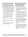
Restoring Power
The auxiliary lamp switch
is located on the center of
the instrument panel
near the climate controls.
When the switch wiring is connected to an auxiliary
roof mounted lamp, pressing the switch will activate
the lamp and illuminate an indicator light near the
switch. Pressing the switch again will turn off the roof
mounted lamp.
1. Be sure that the auxiliary lamp switch is off.
2. Vacate the vehicle and reconnect the battery cable.
3. Turn the auxiliary lamp switch on. The accessory
should now be working. If it is not working, check
the connections.
4. After ensuring that the accessory is working
properly, install the grommet in the hole.
Seal with silicone sealer to prevent water leakage.
This switch includes wiring provisions for a dealer or a
qualified service center to install an auxiliary roof lamp.
14-12
Notice: Overloading the vehicle’s electrical system
may damage your vehicle’s accessories. Do not
overload the vehicle’s system by having
unnecessary accessories on at the same time.
Maintenance
The circuit is fed from the #2 post on the underhood
electrical center and protected by the fuse labeled
#2 post located in the electrical center. Always replace
the fuse with a 30 amp maxi-fuse.
Option B
A.
B.
C.
D.
E.
F.
G.
H.
I.
Black Wire
Orange Wire
To Roof Mounted Lamp
Harness Assembly
Grommet (Roof)
Foam Insulator (Adhesive-Backed)
Harness Connector, Secondary Lock and Terminal
Brown Black Wire
Vehicle Outer Roof Panel
14-13
✍ NOTES
14-14
A
E
Airbags, Questions and Answers About Airbags
and Specialty Law Enforcement Vehicles .......... 1-2
Engine Idle Speed - Alternator Output
(Tahoe Police Package Only) .......................... 2-4
B
I
Brakes ............................................................ 5-2
Instrument Panel Cluster ................................... 3-2
C
O
Canadian Owners ................................................ ii
Owners, Canadian ............................................... ii
Driver Information Center (DIC) .......................... 3-4
Q
Questions and Answers About Airbags and
Specialty Law Enforcement Vehicles ................ 1-2
1
R
Running the Engine While Parked ....................... 2-4
S
Safety Belts
Questions and Answers About Airbags and
Specialty Law Enforcement Vehicles ............. 1-2
SEO
7X6, Spotlamp ............................................ 14-8
9L4, Wiring Provisions for 12-Volt
Power Supply .......................................... 14-3
SEO, 7X7, Spotlamps ...................................... 14-9
Special Equipment Options
Standard with Tahoe Police Package .............. 14-2
Specific Cylinder Unit for Single Key Random Code System ................................... 2-2
Spotlamp
SEO 7X6 ................................................... 14-8
Spotlamps - SEO 7X7 ..................................... 14-9
2
T
Tahoe Police and Special Service Package ..........
Tahoe Police and Special Service Packages .........
Tahoe Police Package and Special
Service Package ........................ 1-2, 2-4, 3-2,
Tahoe Police Package and Special
Service Packages ..........................................
Tires ...............................................................
Pressure Monitor System ...............................
Towing
Trailer ..........................................................
Transmitter Programming - SEO AMF ..................
4-2
5-3
3-4
5-2
5-3
5-3
4-5
2-2
W
Wiring Provisions
12-Volt Power Supply - SEO 9L4 ................... 14-3