1
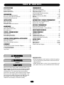
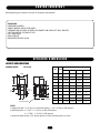
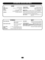
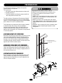
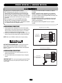
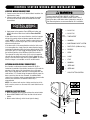
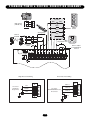
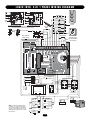
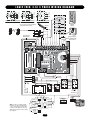
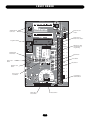
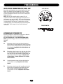
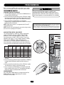
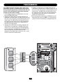
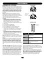
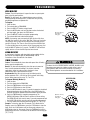
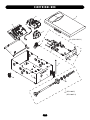
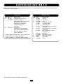
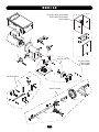
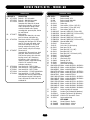
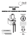
Logic 3
OWNER’S MANUAL
GH
INDUSTRIAL DUTY COMMERCIAL DOOR OPERATOR
This Operator Features
the Enhanced
L
E
PAT E N T P E N D I N G
R
T SYS
E
A
M
E
M
A
T ENA N
C
IN
T
The Maintenance Alert System™ allows the
installer to set an internal Maintenance
Cycle Counter. The Logic 3 operator
incorporates a self-diagnostic feature built
into the (MAS) Maintenance Alert System
LED. An LED on the 3-button station will
signal when the set number of
cycles/months is reached or when the
operator requires immediate service.
Radio Receiver
Built on Board
2 YEAR WARRANTY
315MHz
Serial # Box
Installation Date
NOT FOR RESIDENTIAL USE
TABLE OF CONTENTS
SPECIFICATIONS
PROGRAMMING
Carton Inventory . . . . . . . . . . . . . . . . . . . . . . . . . . . . . . . . . . . . .3
Operator Dimensions . . . . . . . . . . . . . . . . . . . . . . . . . . . . . . . . .3
Operator Specifications . . . . . . . . . . . . . . . . . . . . . . . . . . . . . . . .4
Hand Chain Right/Left Conversion . . . . . . . . . . . . . . . . . . . . . . .5
Disconnect Lever Right/Left Conversion . . . . . . . . . . . . . . . . . . .5
Horizontal Mounting Conversion . . . . . . . . . . . . . . . . . . . . . . . . .5
Logic Control Pushbuttons . . . . . . . . . . . . . . . . . . . . . . . . . . . .16
Determine and Set Wiring Type . . . . . . . . . . . . . . . . . . . . . . . . .16
Failsafe Wiring Types . . . . . . . . . . . . . . . . . . . . . . . . . . . . . . . . .17
Self-Monitoring Safety Device Options . . . . . . . . . . . . . . . . . . . .17
Programming Remotes . . . . . . . . . . . . . . . . . . . . . . . . . . . . .18-19
Maintenance Alert System (MAS) . . . . . . . . . . . . . . . . . . . . . . .20
Mid Stop . . . . . . . . . . . . . . . . . . . . . . . . . . . . . . . . . . . . . . . . . .21
Timer to Close . . . . . . . . . . . . . . . . . . . . . . . . . . . . . . . . . . . .21-22
INSTALLATION
AUTOMATICALLY LEARNED PROGRAMMING
Mount the Operator . . . . . . . . . . . . . . . . . . . . . . . . . . . . . . . . . . .6
Manual Operation . . . . . . . . . . . . . . . . . . . . . . . . . . . . . . . . . . . .7
Entrapment Protection Accessories . . . . . . . . . . . . . . . . . . . . . .8
Auxiliary Reversal System/RPM Sensor . . . . . . . . . . . . . . . . . . .22
Maximum Run Timer (MRT) . . . . . . . . . . . . . . . . . . . . . . . . . . .23
ADJUSTMENT
Red/Green Warning Light Card . . . . . . . . . . . . . . . . . . . . . . . . .23
Resetting Factory Defaults - Clearing Memory . . . . . . . . . . . . . .24
PREPARATION
OPTIONAL PROGRAMMING
Limit Switch Adjustment . . . . . . . . . . . . . . . . . . . . . . . . . . . . . . .8
Adjust Torque Limiter Clutch . . . . . . . . . . . . . . . . . . . . . . . . . . . .9
Brake Adjustment . . . . . . . . . . . . . . . . . . . . . . . . . . . . . . . . . . . .9
MAINTENANCE SCHEDULE . . . . . . . . . . . . . . . . . . . . . . . .24
POWER & GROUND WIRING
TROUBLESHOOTING
Safety Warnings . . . . . . . . . . . . . . . . . . . . . . . . . . . . . . . . . . . .10
Power Wiring Connections . . . . . . . . . . . . . . . . . . . . . . . . . . . .10
Ground Wiring Connections . . . . . . . . . . . . . . . . . . . . . . . . . . .10
Diagnostic Chart . . . . . . . . . . . . . . . . . . . . . . . . . . . . . . . . . . . . .25
Troubleshooting Guide . . . . . . . . . . . . . . . . . . . . . . . . . . . . . . . .26
Troubleshooting Error Codes . . . . . . . . . . . . . . . . . . . . . . . . . . .27
Troubleshooting Radio Functionality . . . . . . . . . . . . . . . . . . . . .28
CONTROL STATION WIRING & INSTALLATION
REPAIR PARTS
Control Wiring Connections . . . . . . . . . . . . . . . . . . . . . . . . . . .11
Mounting Instructions . . . . . . . . . . . . . . . . . . . . . . . . . . . . . . . .11
External Radio Wiring Connections . . . . . . . . . . . . . . . . . . . . . .11
Electrical Box . . . . . . . . . . . . . . . . . . . . . . . . . . . . . . . . . . . .30-31
Repair Parts Kits . . . . . . . . . . . . . . . . . . . . . . . . . . . . . . . . .32-33
Operator Notes . . . . . . . . . . . . . . . . . . . . . . . . . . . . . . . . . .34-35
Control Connection Diagram . . . . . . . . . . . . . . . . . . . . . . . . . . .36
DIAGRAMS
Standard Power & Control Connection Diagrams . . . . . . . . . . .12
1 Phase Wiring Diagram . . . . . . . . . . . . . . . . . . . . . . . . . . . . . .13
3 Phase Wiring Diagram . . . . . . . . . . . . . . . . . . . . . . . . . . . . . .14
Logic Board . . . . . . . . . . . . . . . . . . . . . . . . . . . . . . . . . . . . . . . .15
WARNING
WARNING
IMPORTANT NOTES:
• BEFORE attempting to install, operate or maintain the operator,
you must read and fully understand this manual and follow all
safety instructions.
• DO NOT attempt repair or service of your commercial door and
gate operator unless you are an Authorized Service Technician.
Mechanical
CAUTION
WARNING
WARNING
WARNING
Electrical
WARNING
CAUTION
WARNING
When you see these Safety Symbols and Signal Words on the
following pages, they will alert you to the possibility of serious
injury or death if you do not comply with the warnings that
accompany them. The hazard may come from something
mechanical or from electric shock. Read the warnings carefully.
When you see this Signal Word on the following pages, it will
alert you to the possibility of damage to your door and/or the
door operator if you do not comply with the cautionary
statements that accompany it. Read them carefully.
2
CARTON INVENTORY
Before beginning your installation check that all components were provided.
DESCRIPTION
POWERHEAD ASSEMBLY
OWNER’S MANUAL AND CAUTION LABELS
HARDWARE BOX (INCLUDES FASTENERS, DISCONNECT AND CHAIN HOIST WALL BRACKET)
3-BUTTON CONTROL STATION WITH LED
HOIST HAND CHAIN
DOOR SPROCKET
DOOR/OPERATOR DRIVE CHAIN
O P E R AT O R D I M E N S I O N S
WEIGHTS AND DIMENSIONS
HANGING WEIGHT:
80-110 LBS.
DIMENSIONS
HP
14.00"
14.13"
A
13.25"
D
B
Y
Y
See
Note #1
See
Note #2
X
C
See
Note #3
Hand Chain Wheel
PHASE
A
28-5/8B
C
33D
1/2
1
11-1/2
25-3/4
14.13
3
3/4
1
12-1/2
26-3/4
14.13
3
1
1
12-3/4
27
14.13
3
1-1/2
1
12-3/4
27
15.13
3-1/2
1/2
3
11
25-1/4
14.13
3
3/4
3
11
25-1/4
14.13
3
1
3
12
26-1/4
14.13
3
1-1/2
3
12-1/2
26-3/4
15.13
3-1/2
2
3
12-3/4
27
15.13
3-1/2
3
3
13-1/4
28-5/8
17.13
3
NOTES:
1) Output Shaft with 1" x 1/4" Key for 1/2 thru 2HP operators, 1-1/4" x 1/4" Key for 3HP operators.
2) Mounting Centers: X = 4-3/4"; Y = 5-1/2" for 1/2 thru 2HP operators
X = 7-17/32"; Y = 9-1/16" for 3HP operators
3) Hand Chain Wheel extends 1-5/8" beyond operator in vertical mounting position as shown.
3
O P E R AT O R S P E C I F I C AT I O N S
MOTOR
ELECTRICAL
TYPE: . . . . . . . . . . . . . . . . . . . . . . . . . . . . . . . .Continuous Duty
HORSEPOWER: . . . . . . . . . . . . . .1/2, 3/4. 1, 1-1/2, 2 and 3 HP
SPEED: . . . . . . . . . . . . . . . . . . . . . . . . . . . . . . . . . . .1725 RPM
VOLTAGE: . . . . . . . . . . . . . . . . . . . . . . .115/220/230V 1 Phase,
208/230/380/460/575V 3 Phase
CURRENT: . . . . . . . . . . . . . . . . . . . . . . . .See Motor Nameplate
TRANSFORMER: . . . . . . . . . . . . . . . . . . . . . .24Vac Secondary
CONTROL STATION: . . . . . . . . . . . . . . .NEMA 3-Button Station
Open/Close/Stop w/LED
WIRING TYPE: . . . . . . . . . . . . . . . . . . . . . . . . . . .C2 (Standard)
Momentary contact to OPEN & STOP, constant pressure to
CLOSE, plus wiring for sensing device to reverse and auxiliary
devices to open and close with open override. See pages 16 and
17 for optional wiring types and operating modes.
LIMIT ADJUST: . . . . . . . . .Linear driven, fully adjustable screw
type cams.
MECHANICAL
SAFETY
DRIVE REDUCTION: . . . . . . . . . . . .45:1 for 1/2, 3/4, and 1 HP
44:1 for 1-1/2, 2
42:1 for 3 HP
OUTPUT SHAFT SPEED: . . . . . . . . .38.3 for 1/2, 3/4, and 1 HP
39.2 for 1-1/2 and 2 HP
41.1 for 3 HP
DOOR SPEED: . . . . . . . .4 - 10" per second depending on door
BRAKE: . . . . . . . . . . . . . . . . . . . . .Solenoid actuated disc brake
HOIST WHEEL: . . . . . . .Standard mounting on left or right side
DISCONNECT: . . . . . . . . . .Floor level chain hoist with electrical
interlock for manual door operation.
CLUTCH (Optional): . . . . . . . . . . .Adjustable torque limiter type
SAFETY PHOTO EYES (Optional CPS-L):Through beam or retro
reflective devices used to provide non-contact safety protection.
SAFETY EDGE (Optional): Electric or pneumatic sensing device
attached to the bottom edge of door.
4
WARNING
P R E PA R AT I O N
It is imperative that the wall or mounting surface provide
adequate support for the operator.
This surface must:
a. Be rigid to prevent play between operator and door shaft.
b. Provide a level base.
c. Permit the operator to be fastened securely and with the
drive shaft parallel to the door shaft.
CAUTION
WARNING
WARNING
To prevent possible SERIOUS INJURY or DEATH:
• DO NOT connect electric power until instructed to do so.
• If the door lock needs to remain functional, install an
interlock switch.
• ALWAYS call a trained professional door serviceman if door
binds, sticks or is out of balance. An unbalanced door may
not reverse when required.
• NEVER try to loosen, move or adjust doors, door springs,
cables, pulleys, brackets or their hardware, ALL of which are
under EXTREME tension and can cause SERIOUS personal
INJURY.
• Disable ALL locks and remove ALL ropes connected to door
BEFORE installing and operating door operator to avoid
entanglement.
The safety and wear of the operator will be adversely affected if
any of the above requirements are not met. For metal buildings,
fasten 2" x 2" x 3/16" (or larger) angle iron frames to the building
purlins. Retain 5-1/2" (13.97 cm) between frames.
The GH operator may be mounted on either the right (standard)
or left side of door, and in either a vertical (standard) or
horizontal mounting position. Refer to the steps below if you
require the hand chain and/or disconnect chain to be on the
opposite side of the operator; or if the operator is being mounted
in a horizontal position.
HAND CHAIN RIGHT/LEFT CONVERSION
Remove the two snap rings (1 piece outer, 1 piece inner) on hand
chain shaft assembly. Position roll-pin to fit through cutout in
frame and slide complete shaft assembly through housing and
bevel gear. Insert shaft assembly on opposite side of housing,
and replace bevel gear, bearing, hardware, and snap rings on the
opposite side of shaft in the same manner.
Shaft Support Bracket
with Bearing (Not Provided)
Door Sprocket
DISCONNECT LEVER RIGHT/LEFT CONVERSION
Remove cotterpins on the ends of the disconnect shaft (square
shaft), move the disconnect lever arm to the opposite side, and
replace the cotterpins. Be sure to keep (2) 12 gauge washers on
the side without the lever arm.
HORIZONTAL MOUNTING CONVERSION
Remove cotterpins on the ends of the disconnect shaft (square
shaft), and remove lever. Replace lever using square hole on
opposite end of lever. Reposition sash chain to opposite end of
lever also. Replace cotterpins.
5-1/2" (13.97 cm)
Chain Guide
Hand Chain Wheel
Cutout for Rollpin
(typical both sides)
Disconnect Lever
Cotterpin
5
I N S TA L L AT I O N
IMPORTANT NOTE: Before your operator is installed, be sure the door has been properly aligned and is working smoothly. The
operator may be wall mounted or mounted on a bracket or shelf. If necessary, refer to the preparation on page 5. Refer to the
illustrations and instructions below that suit your application.
MOUNT THE OPERATOR
Figure 1
1. Wall Mount: The operator should generally be installed below
the door shaft, and as close to the door as possible (Figure 1).
Bracket Shelf Mounting: The operator may be mounted either
above or below the door shaft (Figure 2).
IMPORTANT: The shelf or bracket must provide adequate support,
prevent play between operator and door shaft, and permit
operator to be fastened securely and with the drive shaft parallel
to the door shaft.
NOTE: The optimum distance between the door shaft and
operator drive shaft is between 12" - 15" (30.5 - 38.1 cm).
2. Place door sprocket on the door shaft. Do not insert the key at
this time.
3. Place drive sprocket on the appropriate side of the operator. Do
not insert the key at this time.
4. Wrap drive chain around door sprocket and join roller chain
ends together with master link.
5. Raise operator to approximate mounting position and position
chain over operator sprocket.
6. Raise or lower operator until the chain is taut (not tight). Make
sure the operator output shaft is parallel to door shaft and
sprockets are aligned. When in position, secure the operator to
wall or mounting bracket.
7. Align sprockets and secure (Figure 3).
8. Install Hand Chain
Place hand chain around hand chain wheel. Be sure to pass it
through both openings in the chain guide. Remove enough
links so chain hangs approximately 2' (.61 m) above the floor.
9. Mount Chain Keeper / Keyhole Bracket
Using suitable hardware mount the chain keeper approximately
4' (1.22 m)above the floor, near the free hanging chain.
Remove disconnect sash chain from bag and place the end
through the keyhole in the the chain keeper. Remove excess
links if necessary.
Optimum Distance
12 - 15" (30.5 - 38.1 cm)
Typical Right Hand
Wall Mounted Operator
Figure 2
Be sure door sprocket is
properly aligned wiht drive
before securing to shaft.
OPTIONAL
Mounting Bracket
P/N 08-9098
Optimum Distance
12 - 15" (30.5 - 38.1 cm)
Figure 3
Chain Keeper
4' (1.22 m)
above floor
6
I N S TA L L AT I O N
MANUAL OPERATION
WARNING
This operator has provisions for manually operating the door in
case of emergency or power failure. These operators are equipped
with a manual hoist. An electrical interlock will disable the
electrical controls when the hoist is used.
To prevent possible SERIOUS INJURY from a moving chain,
ENGAGE interlock BEFORE manually operating your door.
CAUTION
To operate the hoist:
Chain Keeper
(with pad locking provisions)
1. Pull the disconnect chain (small chain) to engage the interlock
to disable the controls. The disconnect chain may be locked in
position by slipping the end through the keyhole of the chain
keeper mounted on the wall.
2. Operate the door in the desired direction by pulling on one side
or the other of the continuous loop hoist chain (large chain).
3. The disconnect chain must be released from the chain keeper
before the door will operate again electrically.
7
I N S TA L L AT I O N
ENTRAPMENT PROTECTION ACCESSORIES
(OPTIONAL)
WARNING
PHOTO EYES & SENSING EDGES
Sensing devices provided for door industry type operators with an
isolated normally open (N.O.) dry contact output are compatible
with your operator. This includes pneumatic and electric edges,
and through beam and retro reflective photo eyes. If you would
like to order or receive more information on safety devices, please
contact your local Authorized Dealer.
If not pre-installed by the door manufacturer, mount the sensing
edge on the door according to the instructions provided with the
edge. The sensing edge may be electrically connected by either
coiled cord or take-up reel.
Important Notes:
a. Proceed with limit switch adjustments described below before
making any sensing edge wiring connections to operator.
b. Electrician must hardwire the junction box to the operator
electrical box in accordance with local codes.
To reduce the risk of SEVERE INJURY or DEATH, ALWAYS
install reversing sensors when the 3-button control station is
out of sight of door or ANY other control (automatic or manual)
is used. Reversing devices are recommended for ALL
installations.
CAUTION
WIRING
For wiring of your sensing device to the operator, refer to the
wiring diagrams provided on pages 13 and 14. See field
connection terminals identified as Reversing Device.
TAKE-UP REEL
Take-up reel should be installed 12" (30.48 cm) above the top of
the door.
COIL CORD
Connect operator end of coil cord to junction box (not provided)
fastened to the wall approximately halfway up the door opening.
WARNING
ADJUSTMENT
LIMIT SWITCH ADJUSTMENT
CAUTION
WARNING
NOTE: Make sure the limit nuts are positioned between the limit
switches before proceeding with adjustments.
1. Depress retaining plate to allow nut to spin freely. After
adjustment, release plate and move nut back and forth to
ensure it is fully seated in slot.
2. To increase door travel, spin nut away from limit switch. To
decrease door travel, spin limit nut toward limit switch.
3. Adjust open limit nut so that door will stop in open position
with the bottom of the door even with top of door opening.
4. Repeat steps 1 and 2 for close cycle. Adjust close limit nut so
that the limit switch is engaged as door fully seats at the floor.
CLOSE
WARNING
To avoid SERIOUS personal INJURY or DEATH from
electrocution, disconnect electric power BEFORE manually
moving limit nuts.
OPEN
SAFETY
(Aux. Close) Limit Switch
OPEN Limit Switch
CLOSE Limit Switch
8
ADJUSTMENT
ADJUST TORQUE LIMITER CLUTCH
(OPTIONAL MODIFICATION)
1. Loosen set screws on clutch nut.
2. Back off clutch nut until there is very little tension on the clutch
spring.
3. Tighten clutch nut gradually until there is just enough tension
to permit the operator to move the door smoothly but to allow
the clutch to slip if the door is obstructed. When the clutch is
properly adjusted, it should generally be possible to stop the
door by hand during travel.
(3) Set
Screws
Brake
Plate Assembly
Release Lever
BRAKE ADJUSTMENT
The brake is adjusted at the factory and should not need
additional adjustment for the the life of the brake assembly.
Replace brake assembly when necessary. Refer to the illustration
for identification of components for the solenoid type brake
system.
Solenoid
Brake Assembly
Actuator Plate
9
NING
WARNING
POWER WIRING
& GROUND WIRING
ION
WARNING
To reduce the risk of SEVERE INJURY or DEATH:
• ANY maintenance to the operator or in the area near the
operator MUST NOT be performed until disconnecting the
electrical power and locking-out the power via the operator
power switch. Upon completion of maintenance the area MUST
be cleared and secured, at that time the unit may be returned
to service.
• Disconnect power at the fuse box BEFORE proceeding.
Operator MUST be properly grounded and connected in
accordance with local electrical codes. The operator should be
on a separate fused line of adequate capacity.
• ALL electrical connections MUST be made by a qualified
individual.
• DO NOT install ANY wiring or attempt to run the operator
without consulting the wiring diagram. We recommend that
you install an optional reversing edge BEFORE proceeding with
the control station installation.
• ALL power wiring should be on a dedicated circuit and well
protected. The location of the power disconnect should be
visible and clearly labeled.
• ALL power and control wiring MUST be run in separate
conduit.
POWER WIRING CONNECTIONS
Single Phase Power Wiring
1. Connect power wires coming from the main to the captive
terminal block in the electrical box enclosure marked with the
label. All power and control wiring must be run in separate
conduit in accordance with local electrical codes.
2. Be sure to run all power wires through the conduit hole in the
electrical box enclosure marked with the label shown below.
Hot
Line Power
115/230 Vac
Single Phase
NOTE: Must use #14 AWG or thicker wire for power wiring.
Neutral
Gnd
ON THREE PHASE MACHINES ONLY: Incorrect phasing of the
power supply will cause the motor to rotate in the wrong
direction. To change motor rotation, exchange incoming power
leads L1 and L2.
Three Phase Power Wiring
GROUND WIRING CONNECTIONS
1. Connect earth ground to the chassis ground screw in the
electrical box enclosure.
2. Use same conduit entry into the electrical box as the power
wiring.
Phase 1
Line Power
208/230/380/460/575 Vac
Three Phase
IMPORTANT NOTE: This unit must be properly grounded. Failure
to properly ground this unit could result in electric shock and
serious injury.
Phase 2
Phase 3
Gnd
10
C O N T R O L S TAT I O N W I R I N G A N D I N S TA L L AT I O N
CONTROL WIRING CONNECTIONS
WARNING
1. Connect control wires to the P1 terminal block located on the
logic board as shown.
2. Connect conduit with all control wires through the conduit
hole in the electrical box enclosure marked with the label
shown below.
To prevent possible SERIOUS INJURY or DEATH, install
reversing sensors when the 3-button control station is out of
sight of the door or ANY other control (automatic or manual) is
used. Reversing devices are recommended for ALL installations.
CAUTION
CONTROL
WIRING
USE COPPER WIRE ONLY
40-10032B
R31
A
C3Ø
D8
C18
U7
3. Apply power to the operator. Press OPEN push button and
observe direction of door travel and then Press the STOP
button.
If door did not move in the correct direction, check for improper
wiring at the control station or between operator and control
station. NOTE: In “Diag” mode the 3-button control station can be
tested to verify correct wiring of Open, Close and Stop buttons
without moving the door.
If the door moves in the wrong direction and or the limits move
in the wrong direction, simply move the motor direction jumper
located on the logic board from the factory default setting (STD)
to the (REV) pins. This will change the motor rotation as well as
the functional position of the OPEN and CLOSE limit switch’s.
Then relocate the safety limit switch (SLS) only to the opposite
side with the new functional close limit location. Orient the arm
(lever) of the limit switch away from the center. NOTE: The motor
direction change is not available on the DJ and DH models.
D31
24V
AC
14
24 VOLT AC
24V
AC
13
24 VOLT AC
TIMER
DEFEAT 12
TIMER DEFEAT
CMN
11
COMMON
MAS
10
MAINTENANCE ALERT SYSTEM
EYES
9
PHOTO EYES (LiftMaster Only)
EDGE
8
REVERSE
OPEN
7
OPEN
D7
D6
D5
P1Ø
C17
C25
POWER
D4
24V
AC
14
24V
AC
13
D19
TIMER
DEFEAT 12
TIMER
DEFEAT
R8
D17
MAS
D28
4
D23
EYES
CMN
11
MAS
10
EYES
9
EDGE
8
OPEN
7
D15
EDGE
OPEN
D2Ø
CLOSE
D21
STOP
D13
CLOSE 6
TS
STOP
5
CMN
4
DIAG
ROG
CLOSE 6
CLOSE
STOP
5
STOP
CMN
4
COMMON
3
INTERLOCK
2
INTERLOCK
1
SINGLE BUTTON CONTROL
3
2
SBC
D1 E2)
AILSAFE D14
SBC
1
P1
F1
D34
EXTERNAL RADIO WIRING CONNECTIONS
On all models a radio terminal bracket marked R1 R2 R3 is
located on the outside of the electrical enclosure. In B2 mode the
operator will then open a fully closed door, close a fully open
door, stop an opening door, and reverse a closing door from the
radio remote. In TS control wiring the operator will only open the
door or reset the timer to close. However, for additional door
control from a 3-button remote, a commercial three-channel radio
receiver (with connections for OPEN/CLOSE/STOP) is
recommended.
NOTE: If an external radio receiver is being used in place of the
built-in receiver, remove or disconnect the coaxial cable from the
logic board.
SBC
MOUNTING INSTRUCTIONS
OR IN THE AREA NEAR THE OPERATOR MUST
NOT BE PERFORMED UNTIL DISCONNECTING
THE ELECTRICAL POWER AND LOCKING-OUT
THE POWER VIA, THE MAIN DISCONNECT
SWITCH. UPON COMPLETION OF
MAINTENANCE THE AREA MUST BE CLEARED
AND SECURED, AT THAT TIME THE UNIT MAY
BE RETURNED TO SERVICE.
1. Mount WARNING NOTICE beside or below the control station.
2. Mount MAINTENANCE ALERT label to either side of control
station.
3. Mount control station(s) within line of sight of door(s).
Control
Station
Optional
Controls
Maintenance
Alert SystemTM
If light is Flashing
Rapidly, it is time
for routine door
maintenance.
If light is Flashing
Slowly, followed
by a pause, call for
immediate service.
4'
Approximate
Service every
cycles/months
11
STANDARD POWER & CONTROL CONNECTION DIAGRAMS
OPEN
Maintenance
Alert LED
(RD)
R3
Radio Control
(24V DC only)
CLOSE
(WH)
STOP
R2
Open
R1
3-Button
Station
Close
Sensing Edge
Stop
CPS-L &
CPS-LN4
Open/Close
Single Button
Timer Defeat
Switch
Remove Jumper
To Install External
Interlock
Single Phase Power Wiring
Line Power
115/230 Vac
Single Phase
Three Phase Power Wiring
Phase 1
Hot
Line Power
208/230/380/460/575 Vac
Three Phase
Neutral
Gnd
Phase 2
Phase 3
Gnd
12
LOGIC (VER. 3.0) 1 PHASE WIRING DIAGRAM
OPEN
Maintenance
Alert LED
(RD)
(WH)
CLOSE
STOP
Open
230V MOTOR CONNECTION
Sensing
Edge
NOTE: Gray (GY) and purple (PU) motor wires are reversed
for H and HJ right hand models and all GH and J models.
Stop
CPS-L & CPS-LN4
Open/Close
Single Button
Hoist Interlock
When Present
TMR DEF
SWITCH
Remove Jumper
To Install External
Door Interlock
1
D34
P1
SBC
PROG
S8
B2
FAILSAFE
C2
D1
E2
D35
L5
P6
L1
P7
®
(YE)
(BK)
See Motor
Connections
(BR)
MOV
(WH)
0 B 1
MOV
(WH)
4
8
NO
120 / 240
VAC
120
VAC
COM
6
2
C
(WH)
-24 VAC
4
8
2
6
(WH)
(YE)
COIL
+24 VAC
0 A 1
(WH)
(WH)
(WH)
(WH)
COM
(OR) (PU)
(WH)
(WH)
115 / 230
VOLT 1PH.
POWER IN
(B2 C2 D1 E2)
NON FAILSAFE D14
DIAG
FSTS
TS
RELAY B
C77
C71
K3
D3Ø2
ground
(GY)
C78
C11
neutral
L3 L2 L1
hot
F1
SBC
2
4
CMN
3
5
D13
STOP
CLOSE
RELAY A
3
2
D36
C54
1
RADIO
U1
(YE)
(OR)
(WH)
(YE)
(PU)
(WH)
(RD)
(GY)
(YE)
(RD)
(WH)
(PU)
(YE)
(OR)
T
D22
TIMER
ENABLE
TIMER
D27
MRT
D26
SLS
CLS
D24
MID
D16
D25
OLS
MID
J3ØØ
R29
X1
J1
MOTOR
DIRECTION
E1
STOP
7
OPEN
D21
D2Ø
D15
EDGE
OPEN
D23
4
D1
D28
MAS
EYES
D17
R8
D19
TIMER
DEFEAT
POWER
C17
P1Ø
Ø14LGØ657–A Ø14GPØ657–A
C18
D8
P4
CLOSE 6
8
EDGE
9
10
MAS
EYES
11
CMN
13
TIMER
DEFEAT 12
14
24V
AC
D4
24V
AC
(BL)
C25
U7
D5
D6
D7
D31
C3Ø
(YE)
R31
3-Button
Station
Close
C73
115V MOTOR CONNECTION
(PU) (BL)
See Motor
Connections
(GY)
(WH)
(WH)
NOTE: Lock Sensor is provided on Models
DJ and DH only, red wire from main harness
connects to NC on Bypass L/S and to NO on
Lock Sensor switch. White wires connect the
COM on Bypass L/S and Lock Sensor switch to
NC on Open L/S.
(RD)
COM
BYPASS
L/S
(YE)
NC
NC
NO
(WH)
LOCK
SENSOR
(see note at left)
1 2 3 4
RPM Board
NO
(WH)
(RD)
NO
NC
13
(GY)
CLOSE L/S
(YE)
NC
(RD)
COM
NO
NC
(WH)
OPEN L/S
NO
SAFETY L/S
COM
(YE)
(PU)
(WH)
(RD)
(WH)
(OR)
(YE)
COM
(GY)
R1 R2 R3
Radio
LOGIC (VER. 3.0) 3 PHASE WIRING DIAGRAM
T6
T9
T3
(PU)
(BR)
(YE)
J
1
(GY)
(BR)
2
(PU)
3
(BR)
(YE)
OPEN
Maintenance
Alert LED
(RD)
(WH)
(BL/BK)
460V MOTOR CONNECTION
STOP
575V MOTOR CONNECTION
NOTE: Gray (GY) and purple (PU) motor
wires are reversed for H and HJ right hand
models and all GH and J models.
Open
Stop
Open/Close
Single Button
Hoist Interlock
When Present
TMR DEF
SWITCH
Remove Jumper
To Install External
Door Interlock
1
D34
P1
SBC
PROG
(B2 C2 D1 E2)
NON FAILSAFE D14
FSTS
S8
TS
B2
C2
D35
FAILSAFE
E2
RELAY B
P6
C77
C71
K3
C11
P7
D3Ø2
(GY)
C78
®
(PU)
(BR)
(BR)
MOV
See Motor
Connections
(PU)
(OR)
0 B 1
MOV
4
NO
COM
120
VAC
240 / 460 /
575 VAC
COM
(WH)
D
COIL
+24 VAC
8
(WH)
(WH)
NO
2
(WH)
6
COM
(WH)
C
(YE)
NC
NO
(WH)
LOCK
SENSOR
(see note at left)
RPM Board
NC
(RD)
NO
NC
14
(WH)
R1 R2 R3
1 2 3 4
NO
(WH)
(GY)
CLOSE L/S
(RD)
NC
(YE)
COM
NO
(WH)
BYPASS
L/S
6
(GY)
(WH)
NC
(RD)
2
(YE)
(GY)
(WH)
(PU)
NO
COM
8
See Motor
Connections
COM
OPEN L/S
4
COIL
-24 VAC
(RD)
1
(WH)
(YE)
(WH)
A
(YE)
(WH)
0
(WH)
(WH)
(WH)
(OR)
L3 L2 L1
(BK)
(WH)
208/ 230 / 380 / 460
VOLT 3PH.
POWER IN
F1
SBC
4
CMN
2
5
STOP
STOP
CLOSE
RELAY A
D36
3
2
T
D22
TIMER
ENABLE
C54
(WH)
NOTE: Lock Sensor is provided on Models
DJ and DH only, red wire from main harness
connects to NC on Bypass L/S and to NO on
Lock Sensor switch. White wires connect the
COM on Bypass L/S and Lock Sensor switch to
NC on Open L/S.
(YE)
(OR)
(WH)
(YE)
(PU)
(WH)
(RD)
(GY)
(YE)
(RD)
(WH)
(PU)
(YE)
(OR)
1
D16
RADIO
D27
CLS
TIMER
D26
MRT
D24
MID
SLS
MID
J3ØØ
R29
OLS
D25
X1
J1
MOTOR
DIRECTION
U1
D13
D21
D2Ø
D15
EDGE
OPEN
D23
4
D1
D28
MAS
EYES
D17
TIMER
DEFEAT
R8
D19
POWER
C17
P1Ø
Ø14LGØ657–A Ø14GPØ657–A
C18
D8
E1
CLOSE 6
7
OPEN
8
EDGE
9
10
MAS
EYES
11
CMN
13
TIMER
DEFEAT 12
14
24V
AC
D4
24V
AC
(BL)
C25
U7
D5
D6
D7
D31
C3Ø
(YE)
P4
3-Button
Station
Close
Sensing
Edge
CPS-L & CPS-LN4
R31
CLOSE
L5
208/230V MOTOR CONNECTION
3
(BR)
(YE)
T2
DIAG
T3
T8
J
D1
T9
(PU)
T5
(GY)
(BR)
L1
T6
J
(GY)
(BR)
T1
C73
T2
T7
575V BRAKE
T8
J
T4
(WHEN PRESENT)
T5
T1
230V BRAKE
T7
(WHEN PRESENT)
230V BRAKE
(WHEN PRESENT)
(BL/BK)
T4
SAFETY L/S
COM
Radio
LOGIC BOARD
R31
Ø14LGØ657–A Ø14GPØ657–A
P4
C3Ø
D8
E1
C18
U7
Auxilliary Board
Connectors
Motor Direction
Jumper
D31
R29
D7
D6
C11
D5
D3Ø2
P1Ø
X1
U1
K3
C25
C17
POWER
Programmed Chip
D4
Single Phase &
Three Phase Jumper
24V
AC
14
24V
AC
13
D19
J3ØØ
D26
CLS
D27
SLS
D16
TIMER
DEFEAT 12
TIMER
DEFEAT
SINGLE PHASE
D24
STD
MID
CONTACTOR/3 PH D25
MOTOR
DIRECTION
Maximum Run
Timer Button
OLS
REV
J1
R8
D17
MAS
D28
4
D23
EYES
CMN
11
MAS
10
EYES
9
EDGE
8
OPEN
7
Maintenance Alert
System Button for
Programming
Open Button
D15
P7
MID
MRT
TIMER
D1
D22
Radio Learn
Button
RADIO
1
2
EDGE
OPEN
TIMER
ENABLE
3
D36
Close Button
D2Ø
CLOSE
D21
STOP
D13
Stop Button
RELAY A
CLOSE 6
Mid Stop Learn
Button
C77
RELAY B
D35
T
TS
C73
C54
Timer to Close
Learn Button
E2
FSTS
D1
STOP
5
CMN
4
DIAG
3
L1
®
C71
C78
C2
L5
B2
PROG
FAILSAFE
S8
2
SBC
(B2 C2 D1 E2)
NON FAILSAFE D14
SBC
P1
F1
P6
D34
Failsafe Switch
Wiring Type
Selector Dial
15
1
Control Wiring
Terminal Block
PROGRAMMING
LOGIC CONTROL PUSHBUTTONS OPEN, CLOSE, STOP
SELECTOR DIAL
Open, Close and Stop buttons are mounted directly on the logic
board. Thus, making it easy to program as well as have door
control at the electrical box. Either the stop control or a jumper
must be wired between terminals 4 and 5 for the on board push
buttons to function.
NOTE: Refer to logic board illustration on page 15 for all
component locations. Before programming the logic board, set
the operators open and close limits. LEDs on the logic board are
provided to assist setting the limits. As each limit is activated the
corresponding LED will light up. The abbreviations are Open
Limit Switch (OLS), Close Limit Switch (CLS) and Sensing Limit
Switch (SLS). Refer to page 8 for limit switch adjustment
instructions.
FAILSAFE SWITCH
DETERMINE AND SET WIRING TYPE
Read the descriptions of the different wiring types to determine
which setting will be correct for each application.
SET THE SELECTOR DIAL TO THE DESIRED WIRING MODE:
NOTE: For failsafe wiring you must also set failsafe switch to
FAILSAFE.
TYPE
C2
Momentary contact to open and stop with constant
pressure to close, open override plus wiring for sensing
device to reverse. Programmable mid stop available with
this wiring type. Compatible with 3-Button Station and
1-Button Station.
B2
Momentary contact to open, close and stop, plus wiring
for sensing device to reverse and auxiliary devices to
open and close with open override. Programmable mid
stop available with this wiring type. Compatible with
3-Button Station, 1-Button Station and 1 & 3-Button
Remote Controls.
D1
Constant pressure to open and close with wiring for
sensing device to stop. Compatible with 2-Button
Station.
E2
Momentary contact to open with override and constant
pressure to close. Release of close button will cause
door to reverse (roll-back feature) plus wiring for
sensing device to reverse. Compatible with 3-Button
Station.
16
PROGRAMMING
B2 Failsafe Same functions as B2. Self Monitoring safety device
must be installed to operate door for each of the
following failsafe wiring types. See Self Monitoring
Safety Device Options. Compatible with 3-Button
Station, 1-Button Station and 1 & 3-Button
Remote Controls.
FAILSAFE WIRING TYPES
TYPE
TS
T
Momentary contact to open, close, and stop with
open override and Timer To Close. Every device that
causes door to open, including a reversing device,
activates the Timer To Close. Auxiliary controls can
be connected to open input to activate the Timer To
Close. If the timer has been activated, the open
button and radio control can recycle the timer. The
stop button will deactivate the Timer To Close until
the next command input. The Timer To Close will
function from the programmable mid stop with this
wiring type. Compatible with 3-Button Station,
1-Button Station and 1 & 3-Button Remote
Controls. (NOTE: Requires Optional self monitoring
photo eyes to operate.)
D1 Failsafe Same functions as D1. Self Monitoring safety
device must be installed to operate door for each of
the following failsafe wiring types. See Self
Monitoring Safety Device Options. Compatible with
2-Button Station & 2-Button Remote.
E2 Failsafe Same functions as E2. Self Monitoring safety device
must be installed to operate door for each of the
following failsafe wiring types. See Self Monitoring
Safety Device Options. Compatible with 3-Button
Station & 3-Button Remote.
Momentary contact to open, close, and stop, with
open override and Timer To Close. Every device that
causes the door to open, except a reversing device,
activates the Timer To Close. Auxiliary controls can
be connected to open input to activate the Timer To
Close. If the Timer To Close has been activated, the
open button and radio control can recycle the timer.
The stop button will deactivate the timer until the
next command input. The Timer to Close will
function from the programmable mid stop with this
wiring type. Compatible with 3-Button Station,
1-Button Station and 1 & 3-Button Remote
Controls. (NOTE: Requires Optional self monitoring
photo eyes to operate.)
SELF-MONITORING SAFETY DEVICE OPTIONS
To use the operator in any of the Failsafe wiring modes, or Timer
To Close wiring modes (TS, T, FSTS), a self monitoring safety
device or CPS3 card with photo eyes or safety edges must be
installed.
RECOMMENDED SELF-MONITORING SAFETY DEVICES:
CPS-L
NEMA 1 Direct Connect Eyes
CPS-LN4
NEMA 4 Direct Connect Eyes
IMPORTANT NOTES:
1. External interlocks may be used with all functional modes.
2. Auxiliary devices are any devices that have only dry contacts.
Examples: photocell, loop detector, pneumatic or electrical
treadles, radio controls, one button stations, pull cords, etc.
3. Open override means that the door may be reversed while
closing by activating an opening device without the need to use
the stop button first.
FSTS
Momentary button contact for open, close and stop
programming. Radio controls allowing open, close
and stop. User set mid stop. User set Timer To
Close. The single button station opens the door to
the full open limit bypassing the mid stop and
activates the Timer To Close, putting the operator in
TS mode until the door reaches the down limit, or
is stopped in travel. At which time the operator
enters the B2 mode. Compatible with 3-Button
Station, 1-Button Station and 1 & 3-Button
Remote Controls. (NOTE: Requires Optional self
monitoring photo eyes to operate this feature/wire
type.)
C2 Failsafe Same functions as C2. Self Monitoring safety device
must be installed to operate door for each of the
following failsafe wiring types. See Self Monitoring
Safety Device Options. Compatible with 3-Button
Station, 1-Button Station and 1 & 3-Button
Remote Controls.
17
PROGRAMMING
Built in 3-channel, 315MHz radio receiver allows you to add as
many as 23 Security✚® remotes or dip switch remote controls.
WARNING
PROGRAMMING REMOTES
To prevent possible SERIOUS INJURY or DEATH, install
reversing sensors when the 3-button control station is out of
sight of the door or ANY other control (automatic or manual) is
used. Reversing devices are recommended for ALL installations.
STANDARD SINGLE BUTTON REMOTE
1. To enter programming press and release the RADIO button on
the logic board (LED will light).
2. Press and hold the remote button until the LED flashes rapidly,
then release remote button. The LED will then remain on solid
after releasing the button. Repeat to add additional remote(s).
3. Press and release the RADIO button to complete the
programming. The programming mode is exited if no activity is
performed within 30 seconds.
NOTE: Single button remote is not supported with D1 and E2
failsafe wiring modes.
NOTE: Requires self-monitoring photo eyes when using constant
pressure to close (wiring C2, D1 and E2 ).
CAUTION
NOTICE: To comply with FCC and or Industry Canada (IC) rules, adjustment or modifications of this
receiver and/or transmitter are prohibited, except for changing the code setting or replacing the
battery. TH