1
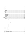
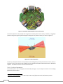
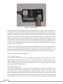
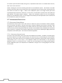
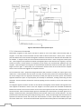
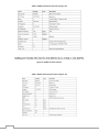
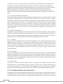
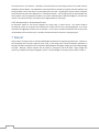
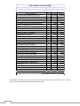
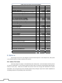
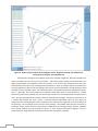
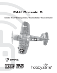
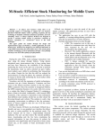
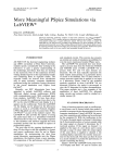
Final Report Team ! Ian Hoffbeck - Tom Kok - Brett Pennings - Christian Swenson 5/11/09 Calvin College TABLE OF CONTENTS Table of Contents ...............................................................................................................................1 1 Introduction ...................................................................................................................................3 1.1 Senior Design ..................................................................................................................................... 3 1.2 Team Description ............................................................................................................................... 3 1.3 Problem Statement ............................................................................................................................ 3 2 Objectives ......................................................................................................................................4 3 Design Norms .................................................................................................................................4 3.1 Transparency ...................................................................................................................................... 4 3.2 Stewardship........................................................................................................................................ 4 3.3 Caring ................................................................................................................................................. 5 3.4 Trust ................................................................................................................................................... 5 4 Project Management ......................................................................................................................5 4.1 Team Organization ............................................................................................................................. 5 4.2 Task Specifications ............................................................................................................................. 5 4.3 Schedule ............................................................................................................................................. 5 5 Design ............................................................................................................................................6 5.1 Airframe ............................................................................................................................................. 6 5.1.1 Airframe Design........................................................................................................................... 6 5.1.2 Airframe Design Alternatives ....................................................................................................... 7 5.1.3 Alternative Radio Controlled Designs .......................................................................................... 8 5.1.4 Airframe Design Challenges ......................................................................................................... 8 5.4 Photographic System ......................................................................................................................... 9 5.4.1 Photographic System Design ....................................................................................................... 9 5.4.2 Photographic System Design Alternatives ................................................................................. 10 5.4.3 Photographic System Design Challenges ................................................................................... 11 5.5 Recovery System .............................................................................................................................. 11 5.5.1 Recovery System Design ............................................................................................................ 11 5.5.2 Recovery System Design Alternative ......................................................................................... 11 5.6 Autonomous Stabilization ................................................................................................................ 12 5.6.1 Stabilization System Design ....................................................................................................... 12 5.6.2 Stabilization Design Alternative ................................................................................................ 14 5.6.3 Design Challenges ..................................................................................................................... 14 5.7 Autonomous Navigation .................................................................................................................. 15 1 5.7.1 Navigation System Design ......................................................................................................... 15 5.7.2 Design Alternatives ................................................................................................................... 19 5.7.3 Autonomous Navigation Challenges ...................................................................................... 19 5.8 User Interface................................................................................................................................... 20 6 Design Alternatives ...................................................................................................................... 20 6.1 Flight System Alternatives................................................................................................................ 20 6.6.2 Alternative to Autonomous Flight ............................................................................................. 21 7 Budget ......................................................................................................................................... 21 8 Results ......................................................................................................................................... 23 8.1 Aerial Pictures .................................................................................................................................. 23 8.2 Autonomous Flight ........................................................................................................................... 24 9 Future Work ................................................................................................................................. 26 10 Lessons Learned ......................................................................................................................... 26 11 References ................................................................................................................................. 28 2 1 INTRODUCTION 1.1 SENIOR DESIGN Senior Design tests the abilities of Calvin engineering students before they enter the work field. The class gives students the freedom to choose a project that will improve their engineering skills, but also benefit the general public. In addition to the projects, the class consists of lectures that prepare the students for the work field. These lectures include guest speakers from the industry along with lectures on issues like communication and team building by Calvin professors. The lectures, combined with the project, will give the students an idea of how a project in the work force will be handled. 1.2 TEAM DESCRIPTION Team ! consists of four undergraduate senior engineers from Calvin College. Names and concentrations for each team member are listed below: Ian Hoffbeck (EE) Christian Swenson (ME) Tom Kok (ME) Brett Pennings (EE) Ian worked at Northrop Grumman this past summer and has an interest in optics. Christian is minoring in mathematics and has interned at Airbus. Tom has a passion for aircraft and has internship experience in optics research. Brett has a computer science minor and internship experience writing in C, an experience which proved useful to the completion of this project. 1.3 PROBLEM STATEMENT The goal of project ! was to design and construct a prototype of a small, low cost, aerial data acquisition system. Unmanned aerial vehicles (UAVs) have long been used by the military in reconnaissance applications, but UAVs have yet to trickle down into the affordable consumer market. However, significant opportunities for such a system exist in many fields including scientific research, search and rescue applications, security monitoring and surveying. Team ! aimed to create a system that would allow small companies and individuals to perform data acquisition that would otherwise be impossible. This system was specifically intended for use by the Calvin College Biology Department to aid their research of canopy composition of the Calvin College Nature Preserve. Aerial pictures will allow for faster and more accurate classification of the species of trees than is currently possible on foot. More importantly, aerial pictures will allow researchers to locate and remove buckthorn trees; an invasive species which threatens some parts of the preserve. 3 2 OBJECTIVES A successful final design and prototype for this project must: 1. Be capable of 5 minutes of sustained flight. 2. Be capable of autonomous navigation, stabilization, and altitude control. 3. Have a simple method for programming flight paths. 4. Have a method of recovery that is safe for both the UAV and the operator. 5. Keep costs below a level acceptable to small research institutions (approx. $500). 6. Be simple to maintain and repair. 7. Include easy to understand operating instructions. 8. Be capable of capturing aerial images. 3 DESIGN NORMS As Christian engineers, it is important to remember that faith in the Lord must play an integral role in every step of the design process. A Christian engineer is responsible to his clients and managers, but ultimately he is responsible to God. This responsibility manifests in many ways throughout the project. He treats his superiors with respect, as God-appointed authorities. He works diligently and honestly. And he continually seeks to understand how this design will affect the world that God has given us and the people who live in it. The process of design from a Christian perspective has been described by a set of design norms, or standards, four of which are explained below in how they relate to this project. 3.1 TRANSPARENCY Transparency was an essential characteristic at two levels. First, the design process needed to be transparent to individuals outside the project. It was important that supervisors, customers, and colleagues were able to look at the project documentation and quickly come to a correct understanding of the successes and shortcomings of the project. For this reason, throughout project ! the design team strove to completely and accurately record the work accomplished. Transparency can also refer to ease of use of a design. This was an especially important consideration with a project like !, which was intended for customers without the technical experience to operate and repair complicated equipment without instructions. To ensure that the final prototype was intuitive, the design team frequently altered the design to aid the end user. For instance, the FTDI cable port for downloading new instructions onto the airplane was installed on the bottom of the aircraft fuselage to provide access without opening the plane and sorting through the other electronics. Several members of the design team also spent time developing a basic user’s manual explaining the process for operating the prototype. 3.2 STEWARDSHIP This project demonstrated stewardship in several ways. The first way was financial stewardship. The aircraft allowed people to capture aerial photographs for a fraction of what they would otherwise spend. Currently a plane must be rented and a photographer must fly over the designated area to take pictures. This can cost thousands of dollars. This project will allow people to take aerial photographs for only a few hundred dollars. The project will also allow smaller organizations and institutions to do research that would be impossible because of the high prices. Additionally, this project demonstrates environmental stewardship because it avoided green house gas emissions. With our device, people will no longer need to rent airplanes to take aerial photographs, substituting the emissions of a small electric motor for those of a large gas engine. 4 3.3 CARING Caring was designed into the concept of the aircraft. This project cared for both the environment and the digital divide. The aircraft showed creation care for the environment because it ran off electricity. This allowed the aircraft create less noise pollution and no carbon emission. The project also reflects caring about people. The digital divide is the idea that the upper class keeps getting more advanced, while the lower economic classes are left with older technologies that leave them disadvantaged to the upper class. This aircraft reduced this divide by allowing researchers with less money to conduct research that was originally too expensive for them. This will allow for such projects as removal of invasive species in nature preserves, improving the ability to take care of these nature preserves. 3.4 TRUST Trust on a project is intimately linked to transparency and extends in many directions. For project !, it was imperative that the team members trust each other; allowing the design and development to proceed in an orderly, unified fashion. It was equally important that the end customer, the Biology Department, trust the design team to carry out the assigned task and create a prototype that meets the design specifications. This trust was maintained through continual, clear communication and proper documentation of the project. 4 PROJECT MANAGEMENT 4.1 TEAM ORGANIZATION Since our team had split concentrations, the team was obligated to specialize in different areas of the project. In a general sense, the mechanical engineers (MEs) dealt with the physical characteristics of the plane and the electrical engineers (EEs) were responsible for the plane’s hardware and software. The Mechanicals were given the task of choosing an airframe and learning to fly the aircraft. Other tasks included rearranging the fuselage to include all necessary components, repairing the airframe when necessary, establishing a stabilization system for the plane and assisting the electrical engineering majors in debugging and programming. The Electricals were in charge of programming the aircraft and integrating the electronics. This included programming the camera control, researching and ordering electronics, analyzing the airplane servos, and assuring correct communication between devices. All members of Team ! conducted research, testing, and revisions based on test results from various subjects. Additionally, all team members helped to complete Senior Design class deliverables. 4.2 TASK SPECIFICATIONS The project was broken down into milestones based on critical tasks. Initially the milestones were divided into mechanical tasks and electrical tasks, but as the project progressed the milestones integrated the electrical and mechanical components. Each concentration set a reasonable time limit to complete these milestones. Throughout the project, each concentration made their own decisions based on their research and then reported to everyone in the group meetings before taking action. If the entire group was in agreement about the decision, then the decision was acted upon. If the decision was rejected, then more research and alternative options were considered until the group agreed on a decision. 4.3 SCHEDULE Completing the project on time was especially important to Team !. The goal was to deliver a functioning prototype to the biology department by the end of the second semester. To do this, the project had to have a clear timeline. The first task was to research how UAVs were built and determine the necessary parts. The second task was to select several of the important electrical components. Then, the process of designing the critical systems of the aircraft began. Each system was advanced through a process of development, testing, and 5 redevelopment. Once a satisfactory design had been achieved, then the project moved on to the next system. The Gantt chart below (Figure 1) shows the progression of the different processes. The development of the navigation and integrated systems was especially heavy in electrical engineering work. To even the load, mechanical work was done concurrently with the design of the electrical systems. 12-Jan 10-Feb 11-Mar 9-Apr 8-May Airframe Assembly Airframe Flight Testing Imaging Integration / Testing Ordering New Navigation Hardware Ordering Stabilization Hardware Navigation Hardware Integration Navigation Software Research Stabilization Hardware Flight Testing Final Report Writing Navigation Hardware Testing Navigation Software Testing New Airframe Integration Navigation Flight Testing User Interface Figure 1: Semester Two Project Gantt Chart 5 DESIGN 5.1 AIRFRAME 5.1.1 AIRFRAME DESIGN 1 The airframe chosen for this project was the Super Cub available from Hobby Zone (see Figure 2) . Figure 2: The Super Cub by Hobbyzone 1 6 RC Hobbies. 2009. 25 Apr. 2009 <http://www.rchobbies.com.au/store/images/hbz7100.jpg>. The Super Cub provided an ideal combination of simplicity, robustness, and power which was necessary for a UAV design. Because the Super Cub was designed for beginner pilots, it was very forgiving of pilot errors: first by the design team and later by the control program. The airframe was also quite sturdy and simple to repair, minimizing the time the team spent between test flights. Additionally, Hobby Zone offered a complete range of inexpensive spare parts. This allowed damaged parts to be replaced quickly. It also had a large fuselage for mounting electronic components. Finally, the Super Cub was chosen because it possessed sufficient power to climb to an altitude of 50 meters with the 160 gram payload required for this project. 5.1.2 AIRFRAME DESIGN ALTERNATIVES 5.1.2.1 C USTOM D ESIGN The first alternative design that was considered was a custom made airframe. The mechanical engineers would have designed the frame to meet the specifications of the project. After assessing the necessary time to customize the airframe and the required calculations, it was decided that buying the airframe was the better option. Another major consideration was the availability of spare parts. If the airframe was custom made, then spare parts would have to be fabricated, consuming extra time and making the design less robust. 5.1.2.2 F LYING W ING Along with a custom design, several types of aircraft were investigated. One option that was discussed was a flying 2 wing. A flying wing consists of a large fuselage, where the entire aircraft acts as a wing. Figure 3 shows an example of a flying wing. Figure 3: A Flying Wing by The Hobby Guy. Research into remote control flying wings found several advantages to using this type of airframe. Flying wings have a wide range of speed that allows the aircraft to slow down to take pictures, but speed up to reach its destination. They also have large fuselages that would allow the components to fit into the body of the plane. Finally, a flying wing is very aerodynamic so that the power draw from the propellers would be decreased. However, there are several drawbacks which led to the rejection of a flying wing airframe. The first problem was stability. A flying wing is not very stable, making the aircraft hard to manage in windy conditions. Since the stabilization system is automated, a more stable aircraft was preferred. The second drawback was that the airframe would be one solid piece. If any part of the airframe were to be damaged the entire airframe would need to be replaced. In a traditional airframe, if the wings are damaged they can be replaced separately for much less than the cost of an entire airframe. Because of these drawbacks, the design team chose a traditional airframe. 2 The Hobby Guy. "Build a Flying Wing For Less Than $5." 22 March 2001. blog.thehobbyguy.tv. http://farm1.static.flickr.com/102/265132238_a96539fa6c_m.jpg 25 April 2009. 7 5.1.3 ALTERNATIVE RADIO CONTROLLED DESIGNS Most of the team’s initial modifications and testing were performed on a Bellanca Decathlon 480 from Hobby 3 Lobby (see Figure 4 ) instead of the Super Cub used in the final design. Figure 4: The Bellanca Decathlon 480 airframe. The Bellanca Decathlon 480 was initially chosen because it was less expensive. Also, the receiver and speed controller in the Bellanca Decathlon 480 were packaged separately, greatly simplifying the task of connecting the existing electronics to the automated flight controller. The Bellanca Decathlon 480 was abandoned because flight tests showed it lacked sufficient power for the payload, because it had less internal room for components than the Super Cub, and because it was less durable than the Super Cub. However, when switching over to the Super Cub, the design team chose to keep the receiver, speed controller, and servos from the Bellanca Decathlon 480 because of their simplicity. Therefore, the final airplane was a hybrid: the fuselage, wings, motor, and other parts of the airframe were from a Super Cub, but the electronics controlling the airplane were from a Bellanca Decathlon 480. 5.1.4 AIRFRAME DESIGN CHALLENGES The primary design challenges were reinforcing the airframe and repairing flight damage. Initial testing revealed that the knobs for the rubber bands which attach the wings to the airframe were points of stress concentration during rough landings. As an initial solution, balsa wood struts were attached to the fuselage immediately adjacent to the knobs to provide strength to the polystyrene body (see Figure 5). 3 8 Flickr. 9 May 2008. 25 Apr. 2009 <flickr.com/photos/mattm/2479061183/>. Figure 5: Close up of the fuselage, showing wing attachment knob and reinforcing balsa wood strut on a Bellanca Decathlon 480 airframe. As the Super Cub did not exhibit these same structural weaknesses, the struts were omitted in the final prototype. Despite efforts to reinforce the fuselage, tears in the polystyrene were not uncommon after flight testing. After some brief experimentation, the team found that traditional wood glue performed extremely well as a bonding agent, and prevented further damage to the polystyrene matrix applied. 5.4 PHOTOGRAPHIC SYSTEM 5.4.1 PHOTOGRAPHIC SYSTEM DESIGN ! used an onboard camera to take pictures while in flight. The GE A830 was selected because of its light weight, low cost and high resolution. Testing showed that in flight images showed a small amount of blurring in some pictures, but the 8.0 megapixel image still had enough resolution to be used for foliage detection and classification. The camera was disassembled before it was installed in the aircraft, and the case, LCD display, and flash were removed to save weight (Figure 6). 9 Figure 6: Finished Camera outside of airframe The photographic system was mounted in the bottom of the fuselage with the camera lens pointed through a hatch in the fuselage bottom. (Figure 7) Figure 7: Camera inside airframe This location allows the camera to take pictures while remaining protected inside the fuselage. The camera was programmed to take a picture every three seconds after the GPS began receiving data. 5.4.2 PHOTOGRAPHIC SYSTEM DESIGN ALTERNATIVES A number of different sensors could have been used in lieu of the optical camera, including IR sensors, temperature sensors, or even a radio tracking device. However, the optical camera had more intuitive and varied uses than any other. Additionally, tracking canopy composition was a primary goal of the biology department, and the optical camera filled this need well. 10 5.4.3 PHOTOGRAPHIC SYSTEM DESIGN CHALLENGES The primary concerns for the photographic system were the weight of the imaging payload, the clarity of the image, and the power system for the camera. First, the airframe needed to be powerful enough to keep the camera aloft for the entire time of the flight. While tests showed that the Super Cub had sufficient power to carry the camera, the weight decreased flight performance. Consequently, the design team worked to reduce the camera weight as much as possible. Second, clear pictures were required for the project to be successful. Ideally, the camera would be mounted on a vibration damping system to increase picture clarity. Unfortunately, time and budget constraints meant such a system was not possible. Instead, the design team shortened the shutter as much as possible and designed the aircraft to take pictures from a high altitude. The combination of these two factors was enough to ensure the pictures taken were of acceptable quality. A third challenge was powering the camera. Originally the camera was designed to receive power from the airplane battery using a voltage regulator. However, the amount of power dissipated by the voltage regulator was too large for the components. Using heat transfer calculations, it was discovered that the circuit would overheat and destroy components in the camera. To solve the problem a second battery was installed in the fuselage specifically for the camera. This created a safer power source for the camera and decreased the chances of electrical failure with the camera. The obvious drawback was the addition of extra weight to the airframe, but this was offset by the reduced power draw on the plane’s battery. Ultimately, testing showed that adding this battery pack for the camera had no important effect on the flight time of the aircraft. 5.5 RECOVERY SYSTEM 5.5.1 RECOVERY SYSTEM DESIGN After considering several alternatives, the design team decided to use manual landing for recovery of the UAV. After the UAV reached the final waypoint, it would return to the point of launch. While it was returning, the pilot would take control from the autonomous system using the transmitter and guide the plane in for a safe landing. A manual landing offered the advantages of simplicity and ease of use. For instructions on the proper landing procedure, see the attached Instruction Manual (Appendix D). 5.5.2 RECOVERY SYSTEM DESIGN ALTERNATIVE Initially, the design team planned to use a parachute to recover the UAV after a mission. The parachute was to be autonomously deployed by the microcontroller after the UAV reached the final waypoint. This plan was adopted because a parachute recovery system provides several advantages: 1. Allows for recovery in the event of guidance/power failure 2. Allows operation in areas with limited open space 3. Protects the airframe from high speed impacts during landing 4. Autonomous fail-safe operation 5. Reduces danger from obstacles at low altitudes The main advantage of a parachute recovery system was that it would provide a means of safe recovery in the event of power or guidance failure. The parachute system would have been composed of a parachute and an electromagnet. During flight, the parachute would be folded and held to the fuselage by the electromagnet. Once the flight finished, the microprocessor would cut power to the electromagnet and the engine. This would allow the parachute deploy from the airplane. Similarly, if a diagnostic check (such as the number of GPS satellites in range) returned an unsatisfactory answer, or if the power failed, the power to the electromagnet would be cut and the parachute would deploy. 11 Also, the parachute system would allow the UAV to operate without a runway. This would make the UAV suitable for field work in a wide range of environments; from city parks to remote wilderness. Despite these advantages, the team eventually decided not to pursue a parachute recovery system. First, the use of a parachute would place large stresses on the airframe and require additional strengthening of the fuselage. Second, the parachute and the electromagnet would add a significant amount of weight to the fuselage, and could have rendered the UAV too heavy to fly. Third, flight testing revealed that manual landing was not as difficult as originally anticipated. Almost all manually controlled landings resulted in no damage to the airframe. Finally, and most importantly, the parachute recovery system required a large investment of time for design and testing. The design team realized that, with limited time resources, the parachute system was not a top priority. 5.6 AUTONOMOUS STABILIZATION 5.6.1 STABILIZATION SYSTEM DESIGN The stabilization system controlled both the roll and the pitch of the plane with the goal of maintaining level flight. The FMA CPD4 Co-Pilot integrated stabilization system was chosen for this project for several reasons. First, the Co-Pilot system was designed to integrate with a wide range of radio controlled airplane designs. This made the system easy to install and operate, saving time for other aspects of the project. Second, research showed similar UAV projects used the Co-Pilot system and reported good results. Third, because it was available in an integrated package including control software, the Co-Pilot system saved the team hours of designing, writing and testing a stabilization program. The Co-Pilot system came in two main parts: the sensor and the controller. These parts are described in the following sections. 5.6.1.1 S ENSOR M ODULE The Co-Pilot sensor module is a small (less than an ounce), black octagon with four infrared thermopiles (see Figure 8). Figure 8: Picture of the Co-Pilot sensor mounted on the airplane. The four thermopiles are mounted orthogonally with one in each direction: forward, backward, left and right 4 relative to the flight direction of the aircraft, as shown in Figure 8 . 4 12 Paparazzi: The Free AutoPilot. 7 Apr. 2009. 25 Apr. 2009 <http://paparazzi.enac.fr/wiki/Other_Infrared_Sensors>. Figure 9: Orientation of thermopiles on the Co-Pilot sensor. The sensor operates on the principle that the ground is distinctly warmer than the sky. Therefore, a thermopile 5 pointed at the ground gives a significantly higher reading than one pointed at the sky, as shown in Figure 10 . Figure 10: IR Sensor Operation In this way, two opposite sensors can only have the same reading if they are both pointed at the horizon, that is, if the plane is level. The IR sensor takes readings from two opposite thermopiles and feeds them into a differential amplifier. This difference is then sent to the microcontroller. 5.6.1.2 C O -P ILOT C ONTROLLER The Co-Pilot system uses an integrated microcontroller (See Figure 11) to interpret and react to the readings gathered by the thermopiles. 5 13 Paparazzi: The Free AutoPilot. 7 Apr. 2009. 25 Apr. 2009 < http://paparazzi.enac.fr/wiki/Infrared_Sensors>. Figure 11: Co-Pilot controller. To increase the accuracy and flexibility of the system, the Co-Pilot has two user inputs. First, before flight the user can adjust the sensitivity of the controller using a small screw connected to a potentiometer. The more sensitive the Co-Pilot is, the greater the roll and pitch corrections will be. This has the advantage of making the aircraft very stable, but it also makes the aircraft slow to respond to inputs from the transmitter. If the sensitivity is turned off, the Co-Pilot will not alter the servo control signals, essentially returning the plane to normal operating mode. In addition to sensitivity control, the Co-Pilot allows the user to calibrate the system before each flight. First, the plane is held with a nose down attitude and the forward and backward thermopiles record the temperature of the sky and the ground. Then the plane is placed in a level position and all four thermopiles record the temperature of the horizon. With this information, the Co-Pilot can compare the readings it receives in flight to readings taken in the same location on the same day. In addition to the sensor module, the Co-Pilot controller was connected to the servo control lines from the plane’s receiver. Based on the differences between the four thermopiles, the controller then calculated how much correction was necessary to maintain level flight, and adjusted the servo control signals accordingly. In this project, the Co-Pilot system was connected to the rudder to correct for roll and the elevators to correct for pitch. 5.6.2 STABILIZATION DESIGN ALTERNATIVE 5.6.2.1 R EMOTE C ONTROL The Super Cub is a remote controlled aircraft. While autonomous stabilization was the end goal of this project, it would be possible to operate the system by remote as well. This would provide the ability for the user to take aerial photographs, but would also require more input on the part of the user. The design team rejected this option as a final objective for this project, but still intended to utilize it as a contingency plan in the event of an incomplete or unreliable stabilization system. 5.6.3 DESIGN CHALLENGES The theoretical principles governing the Co-Pilot operation implied that it would not function properly on cloudy days, or with an obscured horizon. Consequently, the system was tested in a wide variety of situations. It was found that the Co-Pilot system functioned properly in almost any weather condition. Even with significant overcast, the temperature difference between the sky and the ground remained large. Furthermore, after testing, the trees and buildings at the test location were not detrimental to the system. However, one early morning flight demonstrated that, when the sun is on the horizon, the Co-Pilot system can become unstable. Additionally, while 14 the Co-Pilot system functioned reliably among trees, it operated far better when at an altitude above the trees, with a clear view of the horizon. Another challenge was the lack of realistic ground tests for the stabilization system. The elevators and rudder could only control the motion of the aircraft if there was wind passing over the control surfaces, which meant most tests had to be carried out in flight. A failure of the stabilization system at low height and full speed could irreparably damage the airframe or electronics. For this reason, care was taken to perform tests at low speeds and high altitudes, in favorable weather conditions. Finally, time constraints proved to be the most significant limitation on the stabilization system. The more flight tests conducted, the more adjustments to the Co-Pilot could be made before the project was completed. 5.7 AUTONOMOUS NAVIGATION 5.7.1 NAVIGATION SYSTEM DESIGN The autonomous control system used a GPS receiver to obtain four pieces of information: latitude, longitude, course over ground, and altitude. These four values were read by the ArduPilot microcontroller, and used in a pair of algorithms to control aircraft’s heading via the rudder position and the aircraft’s altitude via the motor. The sensor data was processed using software based on the open-source ArduPilot code, developed by the DIY Drones online community. Using open-source software allowed time to be focused on optimizing the flight performance and yielded a more robust system. This code can be found in Appendix E. 5.7.1.1 N AVIGATION S YSTEM L AYOUT The center of the autonomous control system was the ArduPilot microcontroller. In addition to the GPS signals, the manual inputs for the rudder, speed controller, and control line were routed through the microcontroller. Based on the status of the control line, the multiplexer then either allowed the manual inputs to pass through the microcontroller and on to the servos, or the multiplexer allowed the microcontroller to use open-source algorithms, written in C, to control the servos. In either case, the control signal to the rudder passed through the Co-Pilot stabilization system to be adjusted for roll stabilization. See Figure 12 for a wiring diagram of the entire control system. 15 Figure 9: Autonomous Control System Layout 5.7.1.2 N AVIGATION A LGORITHM Autonomous navigation for this project was able to operate in one of two modes: return-to-launch (RTL), or waypoint. In RTL mode, the microcontroller used the rudder to direct the aircraft to a “home” point. The home point was defined as the first latitude and longitude coordinates received from the GPS after the GPS locked onto the satellites. In waypoint mode, the microcontroller directed the aircraft to a series of waypoints chosen by the user. These waypoints were specified in latitude and longitude (where south and west were negative). Once the aircraft was within a certain distance of a waypoint (e.g. 30 meters), the microcontroller updated to the next waypoint. Upon reaching the last waypoint, the microcontroller directed the aircraft to the home point, and then began the course again. In both modes, the microcontroller retained control of the aircraft until the autopilot switch on the transmitter was toggled from autopilot to manual. The microcontroller used a proportional-integral-derivative (PID) controller to modify the output signal to the rudder servo. A PID controller uses the current error value, the time history of the error value (the integral), and the rate of change of the error signal (the derivative) to modify the output of the control system. This balanced approach allowed the system to respond quickly and smoothly to disturbances, avoiding overshooting and wild oscillations. The PID controller could be fine tuned by adjusting the three constants, one for each section of the algorithm. The navigation algorithm used the aircraft’s current latitude and longitude, and the latitude and longitude of the next waypoint to calculate the course to the next waypoint. The control system then calculated the difference between the aircraft’s current course and the course to the next waypoint and sent the resulting course error to the PID controller. After the desired output signal was calculated by the PID controller, the output signal was run through a constraint function, which placed maximum and minimum values on the control responses. This step prevented the aircraft from turning too sharply and losing control. Finally, the output signal was converted into an equivalent microsecond interval and used by the microcontroller to create a pulse width modulated signal to control the rudder servo. The conversion between PID output and microsecond pulse was controlled by user input 16 values for the maximum and minimum pulse widths for each servo. The maximum and minimum pulse widths allowed the microcontroller to determine an output range for each servo. For this project, 1600 microseconds was found to work well as a maximum and 800 microseconds was found to work well as a minimum. 5.7.1.3 A LTITUDE C ONTROL A LGORITHM The altitude of the aircraft was controlled by varying the signal sent to the electronic speed control (ESC), which responded to pulse width modulation just like a servo. Like the navigation algorithm, the altitude control algorithm used a PID controller to change the signal received by the servo (or ESC). In the altitude algorithm, however, the input to the PID controller was the difference between the aircraft’s current altitude and the altitude of the next waypoint. The output from this PID controller was also constrained to prevent the motor from shutting off completely or burning out. To prevent confusion, all of the altitudes used in the control system were relative to the takeoff, or launch altitude. The first altitude value received from the GPS after a satellite lock was stored as the launch altitude. This value was then subtracted from all subsequent altitude readings, giving an altitude reading which accurately reflected the aircraft’s height above the ground instead of its height above sea level. Also, using altitudes relative to the launch altitude allowed the user to input waypoint altitudes without knowing the precise height above sea level. The user simply input the height (in meters) that they wanted the plane to fly above the ground. 5.7.1.4 GPS R ECEIVER AND P ROTOCOL The GPS module for this project was an LS20031 32 channel, 5Hz receiver. These units are capable of communicating with up to 32 satellites simultaneously and sending 6 separate National Marine Electronics Association (NMEA) standardized data sentences 5 times per second. A specialized daughter board lowered the microcontroller’s 5V signal to the 3.3V used by the GPS and provided a path for the GPS data to travel to the microcontroller. Only two NMEA data sentences were required to obtain the GPS information essential to implementing the autonomous control algorithms. These sentences were the recommended minimum navigation data sentence, known as the GPRMC sentence, and the global positioning system fixed data sentence, known as the GPGGA sentence. The GPGGA sentence contains altitude information, while the GPRMC sentence contains the latitude, longitude, and course data. Both sentences come in a specific format. They begin with a header to identify the sentence, continue with data separated by commas, and end with a checksum. The checksum is the result of executing a bitwise XOR command on the entire sentence, and allows the receiver to check for numerical errors. The structure for the GPRMC sentence is shown in Figure 13, and the format of the data is shown in Table 1. The structure for the GPGGA sentence is shown in Figure 14, and the format of the data is shown in Table 2. Figure 13: GPRMC sentence structure. 17 Table 1: GPRMC sentence format (refer to Figure 13). Figure 14: GPGGA sentence structure. Table 2: GPGGA sentence format (refer to Figure 14). 18 The GPS parser, written in C, and integrated into the control code, was responsible for sorting through the data received from the GPS and storing the important information. Normally, it is advisable to send the GPS unit initialization commands which tell the GPS which sentences to send. This reduces the size of the data stream and lightens the load on the microcontroller. However, the GPS unit used in this project did not accept the initialization commands. Therefore, the entire project was carried out with the GPS sending all of its data sentences. Fortunately, the microcontroller parsed out the unnecessary data, and the project as a whole did not suffer. 5.7.1.5 F AILSAFE AND M ANUAL O VERRIDE Before launching the aircraft, the pilot always checked that the GPS had a lock. This could be determined visually by looking for a blinking red LED on the GPS unit itself or a blue LED on the main microcontroller. Taking off without a proper GPS lock would have caused the launch altitude to be incorrectly stored and could have led to the aircraft flying much higher than desired. It was also important for the pilot to keep track of the aircraft during flight. If the GPS receiver lost its lock on all satellites in mid-flight, the plane would have begun to behave erratically and it would be necessary for the pilot to switch to manual control and land the aircraft. This manual override was available at anytime for safety and could be engaged simply by toggling the manual/autopilot switch on the transmitter. 5.7.2 DESIGN ALTERNATIVES Using a GPS receiver for our design was almost essential because of its accuracy and simplicity. It would have been possible to accomplish autonomous control without a GPS, but the other sensors required were more difficult to operate. However, it would be possible in the future to add additional sensors, such as a compass, altimeter, or rate gyro to this project to potentially increase the durability and reliability of the control system. 5.7.2.1 C OMPASS Research showed that compasses do not work well in UAV applications. This is because they spiral into a positive feedback loop when the plane rolls. If the platform of operation was flat, then the compass could be used to determine instantaneous heading as corrective data. This method has potential to be very accurate, but this accuracy could also be compromised by electromagnetic interference from the rest of the system as well. Interfacing with a compass would require more time, money, power, code, ports, and space. This was the least attractive alternative. 5.7.2.2 A LTIMETER An altimeter could be used to determine the height of the aircraft based on air pressure. This is more reliable than GPS because it would give a constant reading. The altimeter could actually be a viable addition to the project because it would allow the plane to launch before locking on to any satellites. However, the accuracy of the unit would depend on the surrounding weather conditions and, similar to the compass, it would require more time, money, power, code, ports, and space. 5.7.2.3 R ATE G YRO A rate gyro is a device that measures angular velocity. The integral of this measurement would yield the instantaneous yaw for the time between GPS refresh intervals. Once the GPS is read again, the actual yaw is corrected and the gyro uses it as its new offset. Research suggested that rate gyros are useful in high-wind conditions, however the marginal gains in performance did not justify the time-costs of installing such a system. 5.7.3 AUTONOMOUS NAVIGATION CHALLENGES The design team encountered several difficulties implementing the control system. The main problem was that the microcontroller did not have sufficient power to provide pulse width modulation at the required 3V. Instead, it provided pulse width modulation at about 1V: not high enough to trigger the servos. Fortunately, the output signal 19 to the rudder travels through the Co-Pilot microprocessor, which increased the signal to 3V. For the signal traveling to the ESC, however, it was necessary to design a circuit capable of increasing the voltage signal. The buffer circuit shown in Figure 15 was used to increase this voltage. Figure 15. ESC Buffer Circuit Diagram By sending the control signal from the microcontroller through this circuit before it reached the ESC, the design team was able correct this problem. The other recurring difficulty with the autonomous control system was flight testing. Because of the nature of the system, it was only possible to do limited tests on the ground. Therefore, several flight tests were required to fine tune the system before it was fully operational. This task was further complicated by the general bad weather encountered at the end of the year. Effective flight tests could only be carried out on days with winds below 10 mph, which greatly limited the time the team could spend finalizing the design. 5.8 USER INTERFACE The ideal user interface would be a full graphical interface which would allow the user to select waypoints by clicking on a map. However, this was not feasible given the time and budget constraints of this project. Instead it was necessary to use a computer to download the desired waypoints into the aircraft before the flight. This task was facilitated by using the mini-USB port installed on the bottom of the plane. Upon return from the flight, the user removed the SD card from the camera (easily accessible after the wings were removed) and downloaded the pictures. 6 DESIGN ALTERNATIVES 6.1 FLIGHT SYSTEM ALTERNATIVES A variety of aerial vehicles were considered at the outset of the project. These vehicles included; airplanes, helicopters, blimps, hot air balloons, and ornithopters. Most of these were rejected because of our project constraints. The blimps and hot air balloons were rejected because in an outdoor environment the craft is subject to wind conditions. The size of the model and the power of the engines would not be sufficient to correct the flight path if there were winds acting on the blimp. The next vehicle investigated was an ornithopter. An ornithopter is designed after birds and uses beating wings to fly. Ornithopters were rejected because the motion of the wings would disrupt the ability of the camera to take pictures. They also consume a lot of power to sustain flight. For these reasons an ornithopter was impractical. A helicopter did have potential because it would allow for easy take off and landing. It could slow down and hover for pictures and it would be able to turn easily. A helicopter was not chosen, however, because it was harder to automate than an airplane. While and airplane 20 constantly moves in one direction, a helicopter must lean forward to start moving forward. This would make the stabilization system difficult. The stabilization system would have to be able to recognize when the helicopter was leaning forward to move and when it was being pushed by the wind. Integrating this system with the navigation system would have been more difficult than in a traditional airplane. The carrying capacity for the helicopter was also a problem. Once the payload was added, it was unclear if the helicopter could sustain flight for more than five minutes. This led to the choice of an airplane as the flight platform for this project. 6.6.2 ALTERNATIVE TO AUTONOMOUS FLIGHT An alternative option for the aircraft navigation was simply using a remote control. The aircraft would be controlled by a pilot on the ground, who would fly the aircraft over the area to be photographed. The camera would then be triggered by a switch on the transmitter. In the event a successful autonomous control system was not developed by the end of the year, a manually controlled aircraft was the team’s contingency plan. 7 BUDGET Project Plane! was begun with the standard $300 budget provided by the Engineering Department. However, it was anticipated that the project might be more costly, so the design team entered the BizPlan competition in December of 2008. Placing first in that competition added $1000 to the budget, bringing the total available budget to $1300. Although a project objective was to produce a prototype for less than $500, a larger budget was necessary to compensate for parts damaged in crashes. The total budget use for this project is shown in Table 3. 21 Table 3: Budget Use for Project ! Beginning Fund Amount Total Left in Fund $1,300.00 $123.94 Item Purchased Bellanca Decathlon 480 RTF Easy Flyer Spare Wing for Bellanca Decathlon Spare Fuselage for Bellanca Decathlon Spare Motor for Bellanca Decathlon Spare Motor Cowl for Bellanca Decathlon Kingston SD4/8GB SDHC Class 4 Flash Card GE A830 Triple Axis Accelerometer ADXL330 FTDI Basic Breakout Arduino Pro Mini - 3.3V/8Mhz Antenna GPS Chip-Scale Antenna GPS 3V Magnetic Mount SMA 20 Channel ET-312 SiRF III GPS Receiver SMA Connector AduPilot-Arduino Compatible UAV Controller Break Away Headers - Straight Connector Vertical SMD for EM401 and EM406 Co Pilot Flight Stabilization System ArduPilote Daughter v11 CAP .1UF 25V Ceramic X7R 0805 CAP Tantalum 1UF 16V 20% SMD IC REG Positive ADJ 1A SOT223 RES 240 OHM 1/8W .1%0805 SMD RES 390 OHM 1/8W .1%0805 SMD RES 10K OHM 1/8W .1%0805 SMD Super Cub Bellanca Decathlon ESC Super Cub Fuselage 32 Channel LS20031 GPS 5Hz Receiver Qty. Unit Cost Total Cost 2 $129.90 $259.80 1 $12.90 $12.90 1 $13.70 $13.70 1 $14.60 $14.60 1 $9.90 $9.90 1 $15.99 $15.99 4 $79.99 $319.96 1 $9.25 $9.25 1 $13.95 $13.95 1 $18.95 $18.95 1 $2.95 $2.95 1 $14.95 $14.95 1 $59.95 $59.95 1 $1.95 $1.95 1 $24.95 $24.95 1 $2.50 $2.50 1 $1.95 $1.95 1 $69.95 $69.95 2 $2.50 $5.00 10 $0.10 $1.00 10 $0.19 $1.90 1 $1.58 $1.58 10 $0.58 $5.80 10 $0.20 $2.00 10 $0.20 $2.00 1 $169.99 $169.99 2 $19.90 $39.80 1 $18.89 $18.89 1 $59.95 $59.95 Total Cost of Purchases: $1,176.06 Unfortunately, the design team was not able to keep the cost of the prototype under $500: the cost of all the parts used in the final prototype was $564 (see Table 4 for details). 22 Table 4: Cost of Parts for Final Prototype Item Purchased Qty. Unit Cost Total Cost Kingston SD4/8GB SDHC Class 4 Flash Card 1 $15.99 $15.99 GE A830 1 $69.99 $69.99 FTDI Basic Breakout 1 $13.95 $13.95 AduPilot-Arduino Compatible UAV Controller 1 $24.95 $24.95 RES 240 OHM 1/8W .1%0805 SMD 1 $0.58 $0.58 RES 390 OHM 1/8W .1%0805 SMD 1 $0.20 $0.20 RES 10K OHM 1/8W .1%0805 SMD 1 $0.20 $0.20 CAP .1UF 25V Ceramic X7R 0805 2 $0.10 $0.20 CAP Tantalum 1UF 16V 20% SMD 2 $0.19 $0.38 Break Away Headers - Straight 25 $0.03 $0.75 Co Pilot Flight Stabilization System 1 $69.95 $69.95 ArduPilote Daughter v11 1 $2.50 $2.50 Super Cub Fuselage 1 $18.89 $18.89 Super Cub Wings 1 $18.99 $18.99 Super Cub Battery 1 $16.99 $16.99 Super Cub Nose Cone 1 $0.99 $0.99 Super Gear Box 1 $8.99 $8.99 Super Cub Motor 1 $10.44 $10.44 Suoer Cub Cowl 1 $2.99 $2.99 Super Cub Complete Tail 1 $11.39 $11.39 Super Cub Rubber Bands 1 $0.99 $0.99 Super Cub Propellor 1 $3.49 $3.49 Super Cub Battery Charger 1 $19.99 $19.99 Bellanca Decathlon ESC 1 $19.90 $19.90 32 Channel LS20031 GPS 5Hz Receiver 1 $59.95 $59.95 Bellanca Decathlon Spare Servos 2 $12.40 $24.80 Velcro 1 $1.92 $1.92 Transmitter and Receiver 1 $80.00 $80.00 Total Cost of Prototype: $500.35 8 RESULTS The prototype of project ! was designed to meet two basic objectives: take aerial pictures, and fly itself to user defined locations using an onboard control system. 8.1 AERIAL PICTURES The final prototype for project ! did effectively take aerial pictures. Several examples of these pictures can be seen in Appendix G. It was found that optimum picture clarity was achieved at high altitude (approximately 150 ft) on sunny days. Under these conditions the pictures were clear enough that individuals were almost identifiable. This is enough clarity for the intended purpose of the prototype: improve the research capabilities of the Biology Department by providing useful, aerial pictures. 23 8.2 AUTONOMOUS FLIGHT The final prototype for project ! never achieved completely autonomous flight. However, separate tests of each component of the control system were reasonably successful; leading to the conclusion that autonomous flight is an attainable objective for a project of this scale. The stabilization system was tested first. Static ground tests were performed where the CoPilot system was calibrated and the aircraft was tipped. Observation of the elevators and rudder revealed that the stabilization system correctly reacted to changes in both pitch and roll. Following those tests, the prototype was flown manually to a safe height for in-flight tests. During these tests the control stick was jerked violently in a random direction by the pilot. The control sticks were then released by the pilot and the reaction of the prototype was observed from the ground. The CoPilot system correctly reacted to every situation and successfully stabilized the aircraft, even when the aircraft was in a vertical dive. In a few situations, the stabilization system was observed to malfunction. For example, early morning tests demonstrated that the CoPilot system was significantly affected by a rising sun. This principle can be extrapolated to dusk flights. Overall, however, the stabilization system exceeded all the expectations of the design team. The navigation system was also tested in gradually increasing levels of complexity. First, a circuit of waypoints in the neighborhood behind Calvin College was loaded onto the plane. The plane was then placed in a car and driven through the waypoint course. Throughout the test, the activity of the onboard control system was monitored using a laptop. During this test, the prototype successfully calculated the course to each new waypoint, and updated the target waypoint after reaching each one. The prototype also turned the rudder in the direction which would take the aircraft toward the next waypoint. Next, the navigation system was tested in an autonomous ground test. A course of four waypoints in the Prince Conference Center parking lot was loaded onto the plane. Without wings attached, the plane was then allowed to taxi itself through the course. The prototype successfully completed the entire course multiple times. The original data from this test can be seen in Figure 16. Note how the prototype does not actually reach the waypoints because the autopilot was designed to update to the next waypoint upon reaching a certain distance from the current waypoint (in this case, 10 meters). 24 Figure 16. Results of the ground test of the navigation system. Waypoints are bold, and numbered 1-4. Prototype course is lighter, and numbered 1-43. The final level of testing for the navigation system was a complete in-flight test. Numerous attempts were made to complete this test, but none were successful. After further ground testing and some discussion, the design team proposed several possible reasons for this failure. First, the wind was a significant factor for such a small airplane and may have been creating excessive interference. Since the autopilot system assumed that the course provided by the GPS was also the heading of the aircraft, if the wind pushed the aircraft sideways it would invalidate the entire autopilot system. The most likely solution to this problem would be to add additional sensors, such as a gyroscope, and a more robust control algorithm which could adjust for wind interference. Second, exhaustive ground testing revealed that the course input received from the GPS appeared to frequently be in error. The team theorized that this was due to the slow airspeed of the prototype. The GPS has a built in error of + 3 meters and refreshes five times a second. If the GPS wandered significantly within this error radius, the magnitude of the resulting apparent velocity would be on the same order of magnitude as the actual velocity of the prototype. This could easily lead to incorrect course readings. This problem could have been overcome by investing in a faster, heavier airframe or by investing in additional sensors and programming. However, regardless of the specific problem the final prototype for project ! never achieved autonomous navigation in the air. Consequently, the design objective of autonomous control was only partially completed. 25 9 FUTURE WORK There are several projects that could improve the aircraft in the future. The first major project would be to make the aircraft completely autonomous. This would be an electrical project that required a lot more coding. The aircraft would have to be able to launch itself, fly to the GPS location and return without human control. The Interface would allow a person to simply load GPS location and then press a button, the aircraft would do the rest. This would make the aircraft more user friendly. The second possible project would be to analyze the body of the aircraft and reinforce the airframe. The objectives of this project would be to make the aircraft more resistant to cracking and breaking from rough landings or hitting trees. This would increase the life of the aircraft. The challenge of the project would be to ensure that the aircraft still had a flight time of five minutes. This would lead to the second part of the project: designing the frame to reduce the amount of drag. The airframe would be optimized for both body integrity and increased flight time. A graphical user interface would provide a third improvement. A program could be written that would allow a user to program the aircraft and retrieve the pictures in a single software suite. The program would include a graphical user interface that was easy to use and could stitch together the captured images. The program would also take into consideration any other features the biology department might want in the system, including plotting the GPS data to see the flight path of the aircraft or storing old flight paths for future reference. This project would be heavily electrical. The fourth potential project would be to solve the problem of wind effects on the aircraft. During the testing phase the results showed that the navigation system could not account for the wind pushing the aircraft. This would lead to incorrect inputs from the GPS to the navigation system. To fix this problem an instrument would need to be added that could tell the orientation of the aircraft. The navigation system would need to be able to differentiate between the direction the aircraft is moving and where the nose of the aircraft is pointing. Currently the code assumes that the direction of travel by the aircraft is the same direction the nose is pointed. This would require integration of a new instrument into the overall system and then modification of the code to use the instrument. A more powerful or heavy airframe may also be required if a reduction in the wind effect is desired. 10 LESSONS LEARNED During the course of project !, the members of the design team gained valuable technical and project management experience. The technical experience included learning how to work effectively with microcontrollers, how to conduct efficient tests, and the basics of control systems. Second and more importantly, the team learned about project management. For instance, as the schedule for ! became tight at the end of the semester it was obvious that it would have been wiser to begin prototyping earlier in the semester or even last fall. A little more time at the end of the project would have gone a long way toward making the final prototype a more robust and capable system. Along the same line, the design team learned it is very important to allow enough time for testing and fine tuning, especially on projects which depend on good weather for testing. In the original project schedule, specific weeks were set aside for testing with the assumption that it would be possible to test during those days. In reality, poor weather canceled many of those scheduled tests and malfunctioning electronics canceled several more. More realistic scheduling of testing, such as building the plane earlier and testing longer, would have improved the overall project. Finally, during this project the design team learned the importance of always having spare parts available. More than once a testing session was cut short because a single part broke and the only way to obtain a new part was to place an order and wait for the part to arrive. The design team should have kept a careful inventory of all the vital parts and ordered a new part as 26 soon as all the spares were used. This approach might have saved as much as a week or two of time. Additionally, Team ! learned how to schedule projects better. If the team members had more project planning experience the schedule would have been more reasonable. Entire sub projects were originally allocated time, but later cut from the project. Redirecting the time associated with the sub projects to necessary system components would have allowed team ! to finish the project sooner. All of these project management lessons could prove very important and useful in future careers, and the members of team ! are grateful for the opportunity to learn through this project. 27 11 REFERENCES Cho, Am, Jihoon Kim, Sanghyo Lee, and Sunjin Choi. "Fully Automatic Taxiing, Takeoff, and Landing of a UAV using a Single-Antenna GPS Receiver only." International Conference on Control, Automation, and Systems 2007 (2007): 821-25. Christophersen, Henrik B. "A compact guidance, navigation, and control system for unmanned aerial vehicles." Journal of aerospace computing, information, and communication 3.5 (2006): 187-213. 24 Oct. 2008. Fujinaga, Jin. "Development of small unmanned aerial vehicle and flight controller design." Collection of Technical Papers - 2007 AIAA Atmospheric Flight Mechanics Conference 2 (2007): 726-41. 24 Oct. 2008. Hardin, Perry J., and Mark W. Jackson. "An Unmanned Aerial Vehicle for Rangeland Photography." Rangeland Photography & Management 58.4 (2005): 439-42. Johnston Jr, Michael G. "Ground object geo-location using UAV video camera." AIAA/IEEE Digital Avionics Systems Conference - Proceedings (2006). 24 Oct. 2008. Lyon, David H. "A Military Perspective on Small Unmanned Aerial Vehicles." IEEE Instrumentation & Measurement Magazine Sep. 2004: 27-31. Online Community of UAV Hobbyists. Ed. Chris Anderson. 24 Nov. 2008. 5 Dec. 2008 <http://diydrones.com/>. Pisano, William J. "Autonomous UAV control using a 3-sensor autopilot." Collection of Technical Papers - 2007 AIAA InfoTech at Aerospace Conference 1 (2007): 423-36. 24 Oct. 2008. Sagahyroon, A. "Design and implementation of a low cost UAV controller." Proceedings of the IEEE International Conference on Industrial Technology 3 (2004): 1394-97. 24 Oct. 2008. Shale, Richard, and John Bader. "Flight Test Results of the Rockwell Migits." IEEE - Position Location and Navigation Symposium (1994): 306-09. The Free Autopilot. 24 Sep. 2008. Paparazzi. 5 Dec. 2008 <http://paparazzi.enac.fr/wiki/index.php/Main_Page>. 28