1
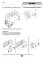
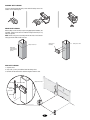
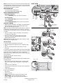
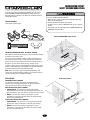
THE PROTECTOR SYSTEM®
WARNING
SAFETY
SENSORS MODEL 916GA
®
WARNING
The Safety Sensor Kit is compatible with Chamberlain® Gate Access
Systems GA400D, GA420D, and GA200D. The Safety Sensors are
designed to detect an obstacle in the path of the electronic beam and
stop the gate operator.
CAUTION
WARNING
To prevent SERIOUS INJURY or DEATH:
• Disconnect ALL electric and battery power BEFORE performing
ANY service or maintenance.
• Correctly connect and align the safety sensors.
• Install the sensor so beam is NO HIGHER than 24" (61 cm) above
ground.
• This product is for use with Chamberlain® GA400D, GA420D, and
GA200D gate operators ONLY.
CARTON INVENTORY
Verify carton inventory below.
Wire Nut (4)
OPEN and ENTRAPMENT Safety Sensors
AVERTISSEMENT
Brackets
AVERTISSEMENT
Safety Sensors
(Includes receiving and sending sensor)
r
nge
a
D
AVERTISSEMENT
ATTENTION
ENTRAPMENT
Safety Sensors
Hex Head Bolt (2)
Wing Nut (2)
ent
m
rapanger
t
n
E D
IMPORTANT INFORMATION ABOUT THE SAFETY SENSORS
When properly connected and aligned, the sensor will detect an obstacle
in the path of its electronic beam.
The sensors must be installed so that the sending and receiving eyes
face each other across the gate, no more than 24" (61 cm) above the
ground. The sensors can be installed on the left or right of the gate as
long as the sun never shines directly into the receiving eye lens.
The safety sensors must be securely fastened to a solid surface such as
metal or a treated wood post (not provided). The light beam path must
be unobstructed during normal operation of the gate.
NOTE: Due to the variety of gates and mounting applications, PVC
conduit, wire, mounting hardware and posts are not provided. Refer to
your local hardware store for additional hardware.
s
EN sor
OP Sen
ty
afe
S
ADVERTENCIA
ADVERTENCIA
CLOSE Safety Sensors
APPLICATIONS
ENTRAPMENT SAFETY SENSORS
This will pause an opening gate until the obstruction has been
removed. Upon removing the obstruction, the gate will continue to
open. This will have no effect on the gate closing.
y
ert
PRECAUCIÓN
e
sid
p
Pro
ADVERTENCIA
In
OPEN (PHOTO EYE/IR) SAFETY SENSORS
• GA400D/GA420D - This will pause an opening gate until the
obstruction has been removed. Upon removing the obstruction, the
gate will continue to open. This will have no effect on the gate closing.
• GA200D - This will stop a closing or opening gate, once the
obstruction is removed the gate will continue to operate normally
upon the next command given.
E rs
OS so
CL Sen
ty
afe
CLOSE (PHOTO EYE/IR) SAFETY SENSORS
• GA400D/GA420D - This will reverse a closing gate to the full open
position (open limit). This will have no effect on a gate opening.
• GA200D - This will stop a closing or opening gate, once the
obstruction is removed the gate will continue to operate normally
upon the next command given.
S
1
WARNING
POWER
CAUTION
Disconnect power and batteries to the operator.
To AVOID damaging gas, power or other underground utility lines,
contact underground utility locating companies BEFORE digging.
SAFETY SENSOR POSTS
Use a metal or treated wood post (not provided) to elevate the sensors.
Safety sensors must be installed no higher than 24" (61 cm) above the
ground.
ENTRAPMENT
Safety Sensor Posts
y
ert
p
Pro
CLOSE
ide
AVERTISSEMENT
Ins Safety Sensor Posts
ty
per
ro
eP
erty
rop
P
e
d
tsi
ATTENTION
Ou
id
Ins
OPEN
Safety Sensor Posts
Wood
OR
Metal
NOTE: For ideal protection the safety sensors should be installed as close
to one another as possible with the maximum distance up to 30' (9.1 m).
TRENCH FOR WIRING
Before digging, contact local underground utility locating companies.
Dig a narrow trench 6" (15 cm) deep from control box to safety sensor
posts. Be careful not to damage any buried wire. Run conduit from
control box to safety sensor posts and run low voltage wire* (not
provided) through conduit.
OPEN SAFETY SENSORS
ADVERTENCIA
ENTRAPMENT SAFETY SENSORS
PRECAUCIÓN
CLOSE SAFETY SENSORS
6" (15 cm) trench
for safety sensor
wires
ty
per
ro
eP
id
Ins
ty
sid
id
Ins
6" (15 cm) trench for
safety sensor wires
ty
per
per
ro
eP
Out
6" (15 cm) trench for
safety sensor wires
*UL approved Class 1 or Class 3 direct burial/underground, sunlight/UV resistant 16 gauge 2-conductor/standard wire.
2
ro
eP
ASSEMBLE SAFETY SENSORS
Insert hex head bolt through safety sensor and slide safety sensor into
bracket. Secure with wing nut.
MOUNT SAFETY SENSORS
Mount safety sensor assembly to post using appropriate hardware (not
provided). Safety sensors must be installed no higher than 24" (61 cm)
above the ground.
NOTE: Install safety sensor assembly with the two holes in the bracket
facing up and the LEDs visible at the top.
Safety Sensor
Assembly
Safety Sensor Post
Mark Safety
Sensor Post No
Higher than 24"
(61 cm)
WIRE SAFETY SENSORS
1. Separate wires.
2. Strip 7/16" (11 mm) of insulation from low voltage wires.
3. Combine all like-colored wires and twist together with wire nuts.
Wire Nuts
Safety Sensor Post
Safety Sensor Wires
Low Voltage
Wires to
Control Box
Conduit
3
Safety Sensor Post
MODEL GA200D
T
JU1
NOTE: If the safety sensor wires need to be extended, the polarity must
be maintained when connecting the safety sensors to the control board.
The black striped wire connects to the negative (-) terminal and the red
wire connects to the positive (+) terminal.
R6
MODEL GA200D ONLY
Black
Striped Wire
Black
Striped Wire
Red
Close
Safety Sensors
Entrapment/Open
Safety Sensors
MODEL GA400D AND GA420D
Black
striped
wires
OPEN EDGE/
PHOTO
Black
Red
Black
Z9
CLOSE
P1
C66
Red
CLOSE
EDGE
C65
C68
J18
CESSORY
0VLD
OPEN EDGE/
DGE/
GE/
Z22
L1
Q6
U4
ON
Black
striped
wires
C75
OFF
C33
F12
LEARN
XMITTER
LOCK /
BIPART DELAY
OPEN
PHOTO
C7Ø
C73
CLOSE
PHOTO
DIAGNOSTIC
F11
R93
SET
OPEN
LIMIT
SET
CLOSE
LIMIT
Q1
GATE 1
K1
Q9
OPEN
PHOTO
TIMER
RUNNING
SINGLE BUTTON
CTRL PWR
OVLD
CONTROL
INPUTS
TIMER TO
CLOSE
J2Ø
FORCE
Red
OPEN
Z8
SINGLE BUTTON
RESET
MAX
OFF
Black
CLOSE
STOP
R186
OFF
Open
Safety
Black Sensors
LEARN
LIMITS
GATE 2
K4
MAX
COM
C12
D44
Red
COM
D8
K3
R184
D4
F7
Z4
LOOP
INPUTS
C13
U3
D2
SHADOW
D129
R9
R196
INTERRUPT
F2
MOV1
CHGR
OVLD
AC PWR
/SOLAR
CTRL PWR
J23
C2
C11
JU1
R329
R27
F3
C69
R42Ø
R423
D1
J24
R4
U2 R22
JU2
MOV2
3ØA
30
K6
C64
32V
DB1
JU1
01-33959C
Q12
C72
K2
TROUBLESHOOTING
If the sending or receiving LEDs do not light up after installation, please
check the following:
• Power supply to the operator. Operator may be in stand-by mode,
press the reset button to wake up the operator. Verify voltage at
inputs.
• A short in the wires. Check wires.
• Incorrect wire connections between the safety sensors and operator.
Verify wiring.
• A broken wire. Check wires.
If both sensors are flashing:
• Align sensors.
• Remove obstruction.
• GA200D - Disconnect safety sensors then turn power on unit.
• GA400D/GA420D - Erase the programming for the safety
sensors - remove safety sensor. Press learn limits button then
press reset button.
Entrapment
Safety
Sensors
CLOSE
PHOTO
Black
striped
wires
Black
Red
Black
Red
Close Safety Sensors
Indicator Light
© 2008, The Chamberlain Group, Inc.
All Rights Reserved
BLU
Red
C71
TEST THE SYSTEM
1. Press the remote control button to open the gate.
2. Place an obstruction in the path of the close or entrapment safety
sensor.
3. Press the remote control button to close the gate. The gate
should stop.
4. Remove the obstruction and the operator will resume normal function.
The gate operator will not function from a remote control if the indicator
light in either sensor is off indicating the sensor is misaligned or
obstructed. If the system continues to fail the test, call for a trained gate
systems technician.
Verify all other safety devices operate correctly.
RED
Red
wires
Black
striped
wires
Black
Striped
Lead
Wire
J19
ALIGN SAFETY SENSORS
1. Reconnect power and batteries to the operator. The indicator lights in
both the sending and receiving eyes will glow steadily if wiring
connections and alignment are correct.
NOTE: The sending eye indicator light will glow regardless of alignment
or obstruction. If the indicator light in the receiving eye is off, dim, or
flickering (and the invisible light beam path is not obstructed), alignment
is required.
2. Loosen the sending eye wing nut and readjust, aiming directly at
the receiving eye. Lock in place.
3. Loosen the receiving eye wing nut and adjust sensor until it
receives the sender’s beam. When the indicator light glows
steadily, tighten the wing nut.
NOTE: When properly aligned, the indicator lights in both the sending
and receiving eyes will glow steadily.
Red
Lead
Wire
_
+
SWITCH
WHT
Entrapment Safety Sensors
• Connect ENTRAPMENT safety sensor wires to P8 terminal.
Open Safety Sensors
• Connect OPEN (Photo Input) safety sensor wires to P7 terminal.
Close Safety Sensors
• Connect CLOSE (Photo Input) safety sensor wires to P9 terminal.
IR
BRN
MODELS GA400D AND GA420D ONLY
_
+
_
+
SWITCH
GRN
+ _
IR
YEL
ALARM
• Insert red lead wire into IR+ terminal.
• Insert black striped lead wire into IR- terminal.