1
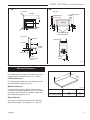
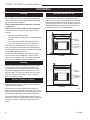
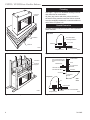
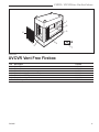
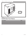
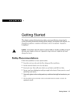
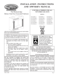
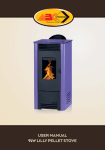
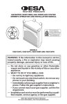
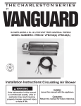
Vent-Free Fireboxes
Models: UVSTR36, UVCVR36
INSTALLER/CONSUMER
SAFETY INFORMATION
DO NOT INSTALL THE APPLIANCE IN
THIS FIREBOX, UNLESS THIS
FIREBOX MEETS THE MINIMUM
DIMENSIONS REQUIRED FOR THE
INSTALLATION.
UVSTR36
WARNING: If the information in this
manual is not followed exactly, a fire or
explosion may result causing property
damage, personal injury or loss of life.
FOR USE ONLY WITH A LISTED
GAS-FIRED, UNVENTED,
DECORATIVE ROOM HEATER NOT TO
EXCEED 40,000 BTU/H
DO NOT BUILD A WOOD FIRE.
DUE TO HIGH TEMPERATURES, THE
APPLIANCE SHOULD BE LOCATED
OUT OF TRAFFIC AND AWAY FROM
FURNITURE AND DRAPERIES.
Do not attempt to modify or alter the
construction of the appliance or its
components. Any modification or
alteration of construction may void the
warranty of these units.
Do not store or use gasoline or other
flammable vapors and liquids in the
vicinity of this or any other appliance.
Improper maintenance or service can
cause injury or property damage. Refer
to this manual. For additional information, consult a qualified installer,
service agency, or the gas supplier.
Carefully review the instructions supplied
with the decorative type unvented room
heater for the minimum fireplace size
requirement.
UVCVR36
Homeowner's Installation
and
FP678
UVSTR/UVCVR
4/20/98
Operating Manual
These Ventless Fireboxes are design
certified to ANSI 21.91.2001 and are for
use with any ANSI Z21.11.2 Unvented
Room Heaters.
DE S I GN
CE
RTIFI E D
INSTALLER: Leave this manual with the appliance.
CONSUMER: Retain this manual for future reference.
7412960 10/06 Rev. 4
UVSTR / UVCVR Series Vent-Free Fireboxes
Description
The UVSTR36 and UVCVR36 models are ventless fireboxes designed for installation with any ventless
gas log set for a see-through application and certified to ANSI Z21.11.2 standards. THESE UNITS ARE
DESIGNED FOR A MAXIMUM OF 40,000 BTU. Optional hoods are available. Refer to page 13.
For Your Safety
• Do not place clothing or other flammable material on or near the appliance.
• Children and adults should be alerted to the hazards of high surface temperature and should stay away
to avoid burns or clothing ignition.
• Young children should be carefully supervised when they are in the same room as the appliance.
Table of Contents
Description and Available Models . . . . . . . . . . . . 2
General Information . . . . . . . . . . . . . . . . . . . . . . . 3
Specifications and Framing . . . . . . . . . . . . . . . . . 4
Clearances . . . . . . . . . . . . . . . . . . . . . . . . . . . . . 5
Installation . . . . . . . . . . . . . . . . . . . . . . . . . . . . . . 6
Maintenance . . . . . . . . . . . . . . . . . . . . . . . . . . . . 10
Replacement Parts . . . . . . . . . . . . . . . . . . . . . . . 11
Accessories . . . . . . . . . . . . . . . . . . . . . . . . . . . . 13
Warranty . . . . . . . . . . . . . . . . . . . . . . . . . . . . . . . 15
2
7412960
UVSTR / UVCVR Series Vent-Free Fireboxes
General Information
DO NOT BURN WOOD OR OTHER MATERIALS IN THESE FIREBOXES.
General Information
The installation must conform with local building codes
or, in the absence of local codes, with the National Fuel
Gas Code, ANSI Z223.1/NFPA 54 (latest edition) and
with the National Electrical Code, ANSI/NFPA70 (latest
edition).
In the Commonwealth of Massachusetts, all gas fitting
and installation of this heater shall only be done by a
licensed gas fitter or licensed plumber.
NOTE: Installation and repair should be done by a qualified service person. The firebox should be inspected
before use and at least annually by a qualified service
person. More frequent cleaning may be required due
to excessive lint form carpeting, bedding material, etc.
It is imperative that control compartment, burners, and
circulating air passageways of the firebox be kept clean.
Any safety screen or guard removed for servicing the
firebox must be replaced prior to operating the firebox.
Provide adequate combustion and ventilation air.
The flow of combustion and ventilation air MUST NOT
be obstructed.
Provide adequate clearance around air openings into
the combustion chamber and adequate accessibility
clearance for servicing and proper operation. NEVER
obstruct the opening of the firebox.
These models may NOT be installed in a bedroom
or bathroom.
Glass doors are NOT available for these fireboxes.
WARNING: Check with your electronics manufacturer before installing a television or other electronic
device above this fireplace.
Installation Precautions
This Majestic Fireplaces firebox and its components
have been tested and will operate safely when installed
in accordance with this installation manual. Read all instructions before starting installation, then follow these
instructions carefully during installation to maximize
firebox benefit and safety. Report to your dealer any
parts damaged in shipment.
This firebox is a highly engineered system. Unless you
use CFM Corporation components which have been
designed for the system, you may create a possible fire
hazard.
CFM Corporation warranty will be voided by, and
CFM Corporation disclaims any responsibility for,
the following actions:
• Installation of any damaged firebox.
• Modification of the firebox or any of the component parts thereof.
• Installation other than as instructed by CFM Corporation.
• Installation and/or use of any component part
or accessory not manufactured or approved by
CFM Corporation in combination or assembly
with a Majestic Fireplaces firebox, notwithstanding any independent testing laboratory or other
third party approval of such component part or
accessory.
Any such action may create a possible fire hazard.
Consult your local building codes.
Proposition 65 Warning: Fuels used in gas, woodburning or oil fired appliances, and the products of
combustion of such fuels, contain chemicals known
to the State of California to cause cancer, birth defects and other reproductive harm.
California Health & Safety Code Sec. 25249.6
Fireplace Screen
The fireplace screen must be in place when the firebox
is operating, and unless other provisions for combustion
air are made, the screen must have openings for the
introduction for combustion air.
WARNING: Be sure to read complete Vent
Free Gas Log Heater and Vent-Free Fireplace Installation and Operating Instructions before installing this product.
7412960
3
UVSTR / UVCVR Series Vent-Free Fireboxes
UVSTR36 Specifications
24"
Rough
Opening �����"
Depth
Rough
Opening
Height
���" Recessed
Nailing
Flange
Rough Opening Width 41"
����"
36"
Gas Line
Access
40���"
��"
36"
12"
14���"
����"
����"
��"
40"
Outside Air
FP676
Fig. 1 UVSTR36 Series specification and framing dimensions.
FP676
UVCVR36 SpecificationsUVSTR36
4/20/98
���" Framing Recess
24"
�����" Rough
Opening
Depth
���" Recessed
Nailing
Flange
Rough
Opening
Height
����"
36"
40���"
��"
36"
��"
Outside
Air
14���"
����"
40���"
Gas Line
Access
����"
12"
FP677
Fig. 2 UVCVR36 Series specification and framing dimensions.
4
FP677
UVCVR36
4/20/98
7412960
UVSTR / UVCVR Series Vent-Free Fireboxes
3A
3B
(Front View)
(Top View)
CEILING
42" Min.
36"
COMBUSTIBLE
MANTEL
TRIM
LEG
FINISHED WALL
MANTEL TRIM
FIREBOX
2"
11" Min.
2"
4¹⁄₂"
4¹⁄₂"
NONCOMBUSTIBLE
FACING MATERIAL
(Side View)
DRYWALL
HEADER
4"
STAND-OFF
(Side View)
8"
MANTEL
SHELF
1¹⁄₂"
8"
12"
Seal with
noncombustible
material
Front leg
of grate
3"
FP679
Fig. 3 Clearances to combustibles.
Minimum Clearances
Sidewall Clearances:
The clearance from the side of the firebox to any combustible wall should not be less than 11" . (Fig. 3A)
Ceiling Clearances:
B
FP679 A
UVSTR/UVCVR clearances
4/17/98
The ceiling height should not be less than 42" from the
top of the fireplace opening. (Fig. 3A)
Mantel Clearances:
If a combustible mantel is installed, it must meet the
clearance requirements detailed in Figure 3A. A mantel
breastplate can be installed at a minimum height of 8"
with a maximum projection of 1¹⁄₂".
Grate Clearance:
FP1545
Front/Back Width Side Width
A
B
FP1545
UVSTR/UVCVR36
29"
17¹⁄₈"
hearth dimensions
Fig. 4 Hearth dimensions.
1/05
The minimum clearance between the front legs of the
grate and front edge of the fireplace is 3" . (Fig. 3B)
7412960
5
UVSTR / UVCVR Series Vent-Free Fireboxes
Installation
Planning
In planning the installation for the firebox it is necessary to determine where the unit is to be installed and
whether optional accessories are desired. Gas supply
piping should also be planned.
These models may NOT be installed in a bedroom
or bathroom.
Glass doors are NOT available for these fireboxes.
Installing Outside Air Kit
An outside air kit may be installed in all UVSTR/CVR
Series fireboxes. If desired, or if local codes mandate the use of an air kit, then an AKU2 is required to
complete the installation (from air kit to out-of-doors).
If the outside air kit is to be used, the AKU2 MUST be
installed BEFORE the fireplace is enclosed. Refer to
the AKU2 instructions for field installation.
The firebox can be mounted on any of the following
surfaces:
•
•
•
A flat hard combustible surface.
A raised platform of combustible or noncombustible
material.
A concrete block or other solid object placed beneath each of the four corners of the appliance.
Nail Top
Standoffs
Nail Eight
Side-Nailing
Flanges
If the firebox is installed directly on carpeting, tile or
other combustible material other than wood flooring, it
should be installed on a metal or wood panel extending
the full width and depth of the unit.
At this point, you should have decided what components to include in your installation, and where the
firebox is to be located. If this has not been done, stop
and consult your dealer for planning assistance.
UVSTR36
Framing
Firebox framing can be built before or after the firebox
is set in place. Framing should be positioned to accommodate wall covering and firebox facing material.
The firebox framing should be constructed of 2 x 4 or
heavier lumber. The framing headers may rest on the
top of the firebox standoffs Refer to Figs. 1 and 2 for
firebox framing dimensions.
Nail Top
Standoffs
Nail Four
Side-Nailing
Flanges
Anchor Firebox in Position
To prevent shifting of the firebox and to maintain sealing
(described later), anchor the firebox. Two methods are
possible for these fireboxes.
One method is to use the eight fastening tabs (four
with cove model) provided with the firebox. (Fig. 5) The
firebox may be secured to the vertical framing members
with these tabs and nails or other suitable fasteners.
UVCVR36
Fig. 5 Adjustable drywall strip (nailing
FP680
FP680
4/20/98
UVSTR/UVCVR36
flange).
The second method uses the standoffs at the front of
the firebox. A nail may be installed through the standoffs
and into the header to stabilize the top of the firebox.
(Fig. 5)
6
7412960
UVSTR / UVCVR Series Vent-Free Fireboxes
Connect the Gas Line
Gas access holes are provided on both sides of the
firebox.
Check gas valve type. Use only the gas type indicated
on the gas log rating plate. If the gas listed on the plate
is not your type of gas supply, DO NOT INSTALL. Contact your Dealer for the proper model.
Always use an external regulator for all LP fireboxes to
reduce the supply tank pressure to a maximum 14" w.c.
This is in addition to the regulator fitted to the vent-free
heater.
WARNING: Connection directly to an unregulated LP tank can cause an explosion.
For final connection of the gas log heater to the gas
line, see Section 5 and Figure 6.
1/2" Gas Supply
NOTE: The gas line connection to the log set can be
made with properly tinned 3/8" copper tubing, 1/2" rigid
pipe, or an approved flex connector. Because some municipalities have additional local codes, it is always best
to consult your local authority.
U.S. INSTALLATIONS – Follow local codes and the
National Fuel Gas Code ANSI Z223.1/NFPA 54.
Always check for gas leaks with a mild
soap and water solution. Do not use an
open flame for leak testing.
When using copper or flex connector use only approved
fittings. Always provide a union so that gas line can
be easily disconnected for burner or fan servicing. See
gas specification for pressure details and ratings.
Cold Climate Insulation
In cold climates, insulation of the enclosure around the
firebox is suggested to avoid problems with cold air.
Insulating the enclosure around the firebox is recommended, but not a requirement
1/2" x 3/8" Shut-Off Valve
3/8" Nipple
3/8" Union
3/8"
Nipple
Gas Supply Line
FP598
Fig. 6 Typical gas supply installation.
Install Gas Log Heater
1. Connect the shutoff valve, union and any required
GF598
approved fittings (See NOTE below) between the valve
nvb GAS SUPPLY INSTALL
and the gas line. 12/4/97
Access to the gas line on the UV Series firebox is made
through the left or right side of the firebox. Locate the
appropriate gas line in the outer casing of the firebox
and remove the insulation from the gas line tube.
The following steps are suggested to minimize cold air
problems.
Insulate the base of the firebox with a noncombustible
insulation. This step is particularly important for outside
wall installations over concrete slab floor construction.
If a platform is used to raise the firebox, the insulation
should be placed onto the platform before the firebox is
set. (Fig. 7)
Refer to Page 5, Figure 3 for minimum clearances to
combustibles.
Inspect joints of the firebox as well as the points of sealing between the firebox and the finishing materials.
When a firebox is installed in a chase or on an outside
wall, the enclosure should be insulated like any other
outside wall of the home. Plywood or hardboard may
be placed on the standoffs and insulation placed on this
surface. (Fig. 8)
From the inside of the firebox, locate the knockout on
the firebrick - be sure you are on the appropriate or gas
line side of the firebox. Using a flat- bladed screwdriver
or small chisel and hammer, carefully tap around the
knockout until it loosens and falls out.
2. Install the Vent-Free Gas Log Heater exactly as
described in the instructions for the heater. If for any
reason, you do not have these instructions, contact
your dealer or manufacturer for another copy.
7412960
7
UVSTR / UVCVR Series Vent-Free Fireboxes
Finishing
Hard Flat
Surface
See Page 5, Figure 3 for allowable finishing materials
and clearances to combustibles.
All joints (top, bottom and sides), where the wall or
decorative facing material meets the firebox surround
must be completely sealed with a noncombustible material. Refer to Figures 9-12.
Hearth Extension
A hearth extension may be used but is not required for
these fireboxes.
Top View
Insulation
Noncombustible
Caulking/Insulation
2 x 4 Stud
Standoff
Platform
FP681
Fireplace Front
Fig. 7 Insulation between firebox and platform.
Finishing Material
FP684
Fig. 9 Seal spaces between firebox and finishing materials.
FP681
4/21/98
UVB
FP684
UVSTR/UVCVR
4/21/98for
See mantel drawing
Insulation
shelf-to-surround dimension
Plywood
Support
Mantel Shelf
Finished Wall
Stud
2 x 4 Finished
Header
Seal with noncombustible material ONLY
Standoff
Surround
Fireplace
Front
Top View
Side
View
1/2"
Finished Wall
FP682
Fig. 8 Additional insulating methods. UVSTR36 shown.
FP682
UVB
4/21/98
8
Fireplace Front
May be sealed with noncombustible
material
FP683
Fig. 10 Surround flush with finished wall.
FP683
UVSTR/UVCVR
4/21/98
7412960
UVSTR / UVCVR Series Vent-Free Fireboxes
4¹⁄₄" Max.
Finished Wall
Must be sealed with
noncombustible material
2 x 4 Finished
Header
Brick Surface
Standoff
Noncombustible
Decorative Facing
Extended
Hood
Surround
FP610
Fig. 11 Appliance surround flush with finish wall.
FP610
1/26/98
2 x 4 Finished Header
FP685
Finished Wall
Covered Wall
Must be sealed with noncombustible material
Noncombustible
Decorative Facing
Fig. 13 Side view of firebox with extended hood.
FP685
4/22/98
UVSTR Side View w/ Hood
Standoff
Surround
FP611
Fig. 12 Facing on firebox flush with finished wall.
Install Hood
FP611
1/26/98
A 2" or 4" Hood can be purchased for the UVSTR36
and the UVCVR36. A Hood must be installed if the
mantel falls within the dimensions and location shown
in Figure 3. Failure to do so may create a fire hazard.
WARNING: When the black surround is covered
by a brick surface, (Fig. 13), use an extended hood.
The hood should extend out to the brick surface
(Refer to Figs. 13 and 14) and be attached to the
firebox. The maximum brick to noncombustible surface that may extend out past the black surround
surface is 4¹⁄₄".
The size of the Hood required depends on BTU ratings
and clearances. See the Accessories section on Page
13 for details.
7412960
Screw
(Fastens to
side rail from
inside hood)
Slot
Use Top Slot
Screw
FP613
Fig. 14 Hood location.
FP613
UVB hood location
1/27/98
9
UVSTR / UVCVR Series Vent-Free Fireboxes
Maintenance
Keep the control compartment, logs and burner area
surrounding the logs clean by carefully vacuuming or
brushing at least twice a year or as necessary.
THE LOGS CAN GET VERY HOT – HANDLE ONLY
WHEN COOL.
Always turn off the gas to the pilot before cleaning. For
relighting, refer to the lighting instructions located on
the Rating Plate of the gas log set.
Never obstruct the flow of combustion and ventilation
air, Keep the front of the appliance clear of all obstacles
and materials.
Firebox
Model and serial numbers are listed on the rating plate (located on right side of combustion
chamber).
Record your model and serial numbers here for
future reference:
Model #
____________________________
Leave at least a 36" clearance from the front of the
firebox to any room furnishings.
Serial #
____________________________
Contact CFM Corporation for questions concerning
prices and policies covering replacement parts. Parts
may be ordered through your Majestic Fireplaces distributor or dealer.
Vent-free Log Heater
You will need the following information when ordering
replacement parts:
Model #
____________________________
Serial #
____________________________
1. The appliance model number.
2. The serial number.
3. A description of the part.
Record your model and serial numbers here for
future reference:
Should you need additional information beyond what
your dealer can furnish, contact:
CFM Corporation
410 Admiral Meadowvale Blvd.
Mississauga, Ontario
Canada L5N 8A3
10
7412960
UVSTR / UVCVR Series Vent-Free Fireboxes
1
2
3
6
4
5
7
CFM Corporation reserves the right to make changes in design, materials, specifications, prices and discontinue colors and products at any time,
without notice.
UVCVR Vent Free Firebox
960
Ref. Description
1. Brick - Filler
2. Brick - Side
3. Brick - Hearth
4. Screen Assembly (Screens and Rod)
5. Brick - Hearth End
6. Screen Assembly - End
7. O.S.A. Assy.
7412960
UVCVR Parts
4/22/98
UVCVR
3079148
3079147
3087102
3036118
3090102
3080137
20003212
11
UVSTR / UVCVR Series Vent-Free Fireboxes
1
2
3
5
4
CFM Corporation reserves the right to make changes in design, materials, specifications, prices and discontinue colors and products at any time,
without notice.
UVSTR Vent Free Firebox
Ref.
1.
2.
3.
4.
5.
12
Description
Brick - Filler
Brick - Side
Brick - Hearth
Screen Assembly (Screens and Rod)
O.S.A. Assy
FP686
UVSTR Parts
4/22/98
UVSTR
3079148
3079147
3087102
3049121
20003212
7412960
UVSTR / UVCVR Series Vent-Free Fireboxes
Accessories
The following accessories for these appliances are available from your local Majestic Fireplaces distributor. Each accessory comes with a separate installation instruction for mounting to the particular firebox. Be sure to read
each instruction thoroughly before installing.
See your Majestic Fireplaces distributor or dealer for other finishing options such as marble and mantels — available
in a wide selection of styles.
Accessory
Outside Air
Description
Completes connection from air kit to out-of-doors
Termination
Model Number
AKU2
Black Finish
2" Hood
4" Hood
4" Hood
4" Hood
For heater up to 40,000 BTU's with a
mantel 8" wide by 28" high
For heater up to 40,000 BTU's with a
mantel 8" wide by 12" high
Extended Hood for brick facings and heater up to
40,000 BTUs and mantel 8" wide by 12" high
Glass Hood for heater up to 40,000 BTUs
and mantel 8" wide by 12" high
Polished Brass
Finish
UV36BH2
UV36PH2
UV36BH4
UV36PH4
UV36BH4E
UV36PH4E
UV36GH4
--
CAUTION: This firebox is a highly engineered system, and, as such, must be operated only with CFM
Corporation approved components. If you use an unapproved component to make any modifications, you
may create a possible fire hazard and will void CFM Corporation warranty. In addition, such action may void
the coverage provided by the owner’s insurance.
7412960
13
UVSTR / UVCVR Series Vent-Free Fireboxes
14
7412960
/ UVCVR Series Vent-Free Fireboxes
LIMITED LIFETIMEUVSTR
WARRANTY
PRODUCT COVERED BY THIS WARRANTY
All Vermont Castings gas stoves, gas inserts, and gas fireplaces, and all Majestic brand gas fireplaces equipped with
an Insta-Flame Ceramic Burner, or standard steel tube burner.
BASIC WARRANTY
CFM Corporation (hereinafter referred to collectively as the Company)
warrants that your new Vermont Castings or Majestic Gas Fireplace/
Stove is free from manufacturing and material defects for a period of
one year from the date of purchase, subject to the following conditions
and limitations.
•
•
EXTENDED LIFETIME WARRANTY
The heat exchanger, where applicable, and combustion chamber
of every Vermont Castings or Majestic gas product is warranted for
life against through wall perforation. All appliances equipped with an
Insta-Flame Ceramic Burner have limited lifetime coverage on the
ceramic burner plaque. Warrantees are made to the original owner
subject to proof of purchase and the conditions and limitations listed
on this Warranty Document
•
•
COMPONENT WARRANTY
CAST IRON: All external and internal cast iron parts are warranted for a
period of three years.
Note: On porcelain enamel finished external parts and accessories
The Company offers no Warranty on chipping of enamel surfaces.
Inspect all product prior to accepting it for any damage to the
enamel.
The salt air environment of coastal areas or a high humidity
environment can be corrosive to the porcelain enamel finish. These
conditions can cause rusting of the cast iron beneath the porcelain
enamel finish, which will cause the finish to flake off.
Dye lot variations with replacement parts and/or accessories can
occur and are not covered by warranty.
GLASS DOORS: Glass doors are covered for a period of one year.
Glass doors are not warranted for breakage due to misuse or accident.
Glass doors are not covered for discoloration or burned in stains due to
environmental issues, or improper cleaning and maintenance.
BRASS PLATED PARTS AND ACCESSORIES: Brass parts should be
cleaned with Lemon oil only. Brass cleaners cannot be used. Mortar
mix and masonry cleaners may corrode the brass finish. The Company
will not be responsible for, nor will it warrant any brass parts which are
damaged by external chemicals or down draft conditions.
GAS VALVES: Gas valves are covered for a period of one year
ELECTRONIC AND MECHANICAL COMPONENTS: Electronic and
mechanical components of the burner assembly are covered for one
year. All steel tube burners are warranted for one year.
ACCESSORIES: Unless otherwise noted all components and CFM
Corporation company supplied accessories are covered for a period of
one year.
CONDITIONS AND LIMITATIONS
•
•
•
•
This new Vermont Castings or Majestic product must be installed by
a competent, authorized, service contractor. A licensed technician, as
prescribed by the local jurisdiction must perform any installation/service
work. It must be installed and operated at all times in accordance with
the Installation and Operating instructions furnished with the product.
Any alteration, willful abuse, accident, or misuse of the product shall
nullify this warranty.
This warranty is non-transferable, and is made to the original owner,
provided that the purchase was made through an authorized supplier
of the Company.
The customer must pay for any Authorized Dealer in-home travel fees
or service charges for in-home repair work. It is the dealers option
whether the repair work will be done in the customer’s home or in the
dealer’s shop.
If upon inspection, the damage is found to be the fault of the
manufacturer, repairs will be authorized at no charge to the customer
parts and/or labor.
7412960
•
•
•
•
•
•
•
Any part and/or component replaced under the provisions of this
warranty is covered for six months or the remainder of the original
warranty, whichever is longest.
This warranty is limited to the repair of or replacement of part(s) found
to be defective in material or workmanship, provided that such part(s)
have been subjected to normal conditions of use and service, after
said defect is confirmed by the Company’s inspection.
The company may, at its discretion, fully discharge all obligations
with respect to this warranty by refunding the wholesale price of the
defective part(s)
Any installation, labor, construction, transportation, or other related
costs/expenses arising from defective part(s), repair, replacement,
or otherwise of same, will not be covered by this warranty, nor shall
the Company assume responsibility for same. Further, the Company
will not be responsible for any incidental, indirect, or consequential
damages except as provided by law.
SOME STATES DO NOT ALLOW FOR THE EXCLUSION OR
LIMITATIONS OF INCIDENTAL AND CONSEQUENTIAL DAMAGES
OR LIMITATIONS ON HOW LONG AN IMPLIED WARRANTY
LASTS, SO THE ABOVE LIMITATIONS MAY NOT APPLY TO YOUR
CIRCUMSTANCES. THIS WARRANTY GIVES YOU SPECIFIC
RIGHTS AND YOU MAY HAVE OTHER RIGHTS WHICH VARY FROM
STATE TO STATE.
All other warranties-expressed or implied- with respect to the product,
its components and accessories, or any obligations/liabilities on the
part of the Company are hereby expressly excluded.
The Company neither assumes, nor authorizes any third party to
assume on its behalf, any other liabilities with respect to the sale of
this Vermont Castings or Majestic product
The warranties as outlined within this document do not apply to
chimney components or other non CFM Corporation accessories used
in conjunction with the installation of this product..
Damage to the unit while in transit is not covered by this warranty but
is subject to claim against the common carrier. Contact the dealer
from whom you purchased your fireplace/stove (do not operate the
appliance as this might negate the ability to process the claim with the
carrier).
The Company will not be responsible for:
a) Down drafts or spillage caused by environmental conditions such
as near-by trees, buildings, roof tops, hills, or mountains.
b) Inadequate ventilation or negative air pressure caused by
mechanical systems such as furnaces, fans, clothes dryers, etc.
This warranty is void if:
a) The fireplace has been operated in atmospheres contaminated by
chlorine, fluorine, or other damaging chemicals.
b) The fireplace has been subjected to prolonged periods of
dampness or condensation
c) Any damages to the fireplace, combustion chamber, heat
exchanger or other components due to water, or weather damage,
which is the result of but not limited to, improper chimney/venting
installation.
d) Any alteration, willful abuse, accident, or misuse of the product
has occurred.
IF WARRANTY SERVICE IS NEEDED…
1) Contact your supplier. Make sure you have your warranty,
your sales receipt, and the model/serial number of your
CFM Corporation product.
2) DO NOT ATTEMPT TO DO ANY SERVICE WORK
YOURSELF.
15
CFM Corporation
2695 Meadowvale Blvd. • Mississauga, Ontario, Canada L5N 8A3
800-668-5323 • www.cfmcorp.com