1
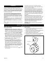
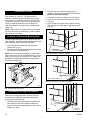
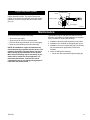
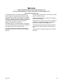
Installation and Operating
Instructions for Unvented
Gas Log Heaters
DE S I GN
CE
RTIFI E D
Thermstatically Controlled Double Burner
Certified to ANSI Z21.11.2A
Models:
UC181N, UE181N, UC241N, UE241N (Natural Gas)
UC181L, UE181L, UC241L, UE241L (Propane)
Standard
Decorative Gas Appliance For Installation In Solid Fuel Burning Fireplaces
WARNING
If the information in this manual is not followed exactly, a fire or explosion may result causing
property damage, personal injury or loss of life.
ATTENTION
— Do not store or use gasoline or other flammable vapors and liquids in the vicinity of
this or any other appliance.
— WHAT TO DO IF YOU SMELL GAS
• Do not try to light any appliance.
• Do not touch any electrical switch; do not
use any phone in your building.
• Immediately call your gas supplier from a
neighbor’s phone. Follow the gas
supplier’s instructions.
• If you cannot reach your gas supplier, call
the fire department.
Installation, service, and repair of this appliance must be performed by a qualified
installer, service agency, company or gas
supplier experienced with this type of gas
appliance.
INSTALLER:
Read these instructions completely and carefully prior to beginning installation. The installer
should initiate the startup procedure and operate the gas log heater for a minimum of 15-30
minute test burn. After installation, leave these
instructions with the owner.
OWNER:
WARNING
This appliance is for installation in a a solid fuel
burning fireplace or approved ventless enclosure. Do not install this appliance in bedrooms,
bathrooms, mobile homes or recreational
vehicles.
ATTENTION
This is an unvented gas fired heater. It sues air
(oxygen) from the room in which it is installed.
Provisions for adequate combustion and ventilation air must be provided.
Read these instructions and follow the warnings. Save this manual for future reference.
WARNING
Keep appliance clear and free from combustible
materials, gasoline and other flammable vapors
and liquids.
WARNING
Any changes to this heater or its controls can be
dangerous.
WARNING
Before installing in a solid fuel burning fireplace, the chimney flue and firebox must be cleaned of soot,
creosote, ashes and loose paint by a qualified chimney cleaner.
CFM Home Products
2695 Meadowvale Blvd. • Mississauga, Ontario, Canada L5N 8A3
800-668-5323
3311243 7/04 Rev. 1
ATTENTION
This unvented gas log heater has been certified by CSA and tested to conform to ANSI Z21.11.2 Gas
Fired Room Heaters. Check local codes before installing this log heater. In some areas of the country,
unvented gas log heaters are restricted.
The installation and provision for combustion and ventilation air must conform with the National Fuel Gas
Code, ANSIZ223.1/NFPA 54 (latest edition), the National Electrical Code, ANSI/NFPA 70 (latest edition)
and any applicable local codes.
You must provide adequate clearances around air openings into the combustion chamber and adequate
clearance for servicing and proper operation.
WARNING
WARNING
Do not use this appliance or any part that has
been under water. Immediately call a qualified
service technician to inspect the appliance and to
replace any part of the control system and any
gas control which has been under water.
Due to high temperatures, the appliance should
be located out of traffic and away from furniture
and draperies. Children and adults should be
alerted to the hazards of high surface temperature and should stay away to avoid burns or
clothing ignition.
WARNING
Young children should be carefully supervised
when they are in the same room with the heater.
Do not allow children to touch or operate this gas
log heater.
WARNING
Improper installation, adjustment, alteration,
service or maintenance can cause injury or
property damage. For assistance or additional
information consult a qualified installer, service
agency or the gas supplier.
WARNING
Clothing or other flammable material should not be placed on or near the appliance.
WARNING
Solid fuels shall not be burned in a fireplace where an unvented room heater is installed.
TECHNICAL INFORMATION
Gas Pressure Testing: This gas heater and its individual shut-off valve MUST be disconnected from the
gas supply piping system during any pressure testing of that system at test pressures in excess of 1/2
psig (3.5kPa). The gas heater must be isolated from the gas supply piping system by closing its individual manual shut-off valve during any pressure testing of the gas supply piping system at test pressures equal to or less than 1/2 psig (3.5kPa).
Component Parts: Only factory authorized components listed in these instructions may be used in
accordance with the manufacturer’s instructions and all codes and requirements of the authority having
jurisdiction. Any modifications to this gas heater, or use of unauthorized components or accessory items
will void the manufacturer’s warranty, and may result in a hazardous condition.
2
3311243
CARBON MONOXIDE POISONING MAY LEAD TO DEATH
When used without fresh air, vent free gas logs may give off carbon monoxide, an odorless, poisonous
gas. Some people such as pregnant women, people with heart or lung disease and persons at high
altitudes are more affected by carbon monoxide than others.
Early signs of carbon monoxide poisoning resemble the flu: Headache, dizziness and/or nausea. If you
have these signs, the heater may not be installed or working properly. Get fresh at once! Have the
heater and chimney serviced before using again.
Before You Begin -- Attention!
A. Do not allow fans to blow directly into the fireplace. Avoid any drafts that alter burner flame patterns.
B. Do not use a blower insert, heat exchanger insert or other accessory not approved for use with this
heater.
C. Any outside air ducts and/or ash dumps in the fireplace shall be permanently closed at time of appliance installation.
D. The appliance should be inspected before use and at least annually by a professional service person.
More frequent cleaning may be required due to excessive lint from carpeting, bedding material, etc. It
is imperative that control compartments, burners and circulating air passageways of the appliance be
kept clean.
E. Your fireplace must include a chain mesh or similar screen. The screen must remain fully closed while
operating your log set. Any safety screen or guard removed for servicing this appliance must be
replaced prior to operation.
F. If your fireplace includes glass doors, they must remain fully open to allow for combustion air during
operation, and to prevent overheating of the gas valve.
G. Your log set must be installed in a solid fuel burning fireplace constructed of noncombustible material.
H. If this log set is to be used with propane gas, your propane supply tank must include a high to low gas
pressure regulator, and must be located outside. DO NOT place supply tanks inside any structure.
I. Be sure to apply pipe joint compound to all non-flared, threaded connections involved in this installation to avoid possible gas leaks. Compounds used in liquid propane applications must be resistant to
the action of that gas.
J. Always test for leaks using a soapy solution. NEVER US AN OPEN FLAME!
K. The manufacture and shipping of your log set involves compounds which may cause detectable yet
harmless odors during initial operation. Provide extra ventilation to the room for the initial 2-3 hour
break in period.
3311243
3
Provisions for Adequate Combustion and Ventilation Air
This heater shall not be installed in a “ CONFINED SPACE” or unusually tight construction unless provisions are provided for adequate combustion and ventilation air.
The NATIONAL FUEL GAS CODE, ANSI Z223.1/NFPA 54 defines a “CONFINED SPACE” as a space
whose volume is less than 50 cubic feet per 1000 BTU per hour (4.8m3 per kw) of the aggregate input
rating of all appliances installed in that space, and an “UNCONFINED SPACE” as a space whose volume
is not less than 50 cubic feet per 1000 BTU per hour (4.8m3 per kw) of the aggregate input rating of all
appliances installed in that space. Rooms communicating directly with the space in which the appliances
are installed, through openings not furnished with doors, are considered a part of the unconfined space.
Determining if You Have Adequate Combustion and Ventilation Air in Your Space
1. Determine the volume of space, (length x width x height). Include adjoining rooms connected by
doorless passageways or ventilation grilles.
Example: A room that is 25’ x 18’ x 8’ has a volume of 3,600 cubic feet. If additional ventilation
to adjoining rooms is supplied with grilles or openings, add the volume of these rooms to the
total volume of the space.
2. Divide the volume of space by 50 cubic feet. The result is the maximum BTU/Hr the unconfined space
can support.
Example: 3,600 cubic feet divided by 50 = 72 or 72,000 BTU/Hr (maximum Btu/Hr the space can
support.)
3. Add the BTU/Hr ratings of all fuel-burning appliances installed in the same space. NOTE: Do not
include direct vent appliances as these utilize outside air for combustion and vent to the outdoors.
Example: Gas range (55,000 BTU/Hr) + Vent Free Heater (39,000 BTU/Hr) = Total 80,000 BTU/Hr.
4. Compare the maximum BTU/Hr rating the space can support with the total BTU/Hr used by the
appliances.
Example: 72,000 BTU/Hr - Max. the space can support. 94,000 BTU/Hr - Total used by the
appliances. In this example, the minimum BTU/Hr the space can support is less than the total
BTU/Hr used by the appliances. The space is considered “CONFINED SPACE”. Additional air
must be provided to meet the requirements of the vent free heater.
If you have no other fuel burning appliances located in the space, then the minimum necessary space you
would need for this 39,000 BTU/Hr maximum heater is 1950 cu. ft. An example of such a room would be
one with a length of 22’, width of 12’, and a standard 8’ ceiling - 22’ x 11.5’ x 8’ = 2,024 cubic feet.
WARNING
If the area in which the heater may be operated is smaller than that defined as an unconfined space or if
the building is of unusually tight construction, provide adequate combustion and ventilation air by one of the
methods described in the National Fuel Gas Code, ANSI Z223.1/NFPA 54.
4
3311243
Installation Guidelines
The fireplace must meet the minimum dimensions listed below. (Fig. 1) Do not install the logset if the fireplace does
not meet these minimums.
Logset
Minimum Fireplace Dimensions
A
B
C
D
Front
Rear
Width
Width
Depth
Height
29”
19”
14”
17”
29”
19”
14”
17”
29”
23”
14”
17”
29”
23”
14”
17”
29”
19”
14”
17”
29”
19”
14”
17”
29”
23”
14”
17”
29”
23”
14”
17”
Gas
18” - UC181N
18” - UE181N
24” - UC241N
24” - UE241N
18” - UC181L
18” - UE181L
24” - UC241L
24” - UE241L
Natural
Propane
Min. Input
BTU/Hr.
25,000
25,000
25,000
25,000
25,000
25,000
25,000
25,000
Max. Input
BTU/Hr.
39,000
39,000
39,000
39,000
39,000
39,000
39,000
39,000
Fireplace Spacing Requirements
The illustration in Figure 2 shows spacing requirements
for your room with a hood installed (not included).
Without a hood, you must maintain a minimum of 32”
between the top opening of the firebox and the bottom
of a mantel which protrudes out 12”. If you do not have
at least 32” between the two, a hood must be installed.
D
B
With a hood installed, you must maintain a minimum
of 24” between the top opening of the fireplace and the
bottom of the mantel.
C
A
FD370-2
Fig. 1 Minimum fireplace dimensions.
NOTE: The distance between any combustible
material and the top opening of the fireplace must
be a minimum of 18” above the opening.
Without Hood
With Hood
Ceiling
12"
12"
42"
Noncombustible
Material
Noncombustible
Material
32"
Min.
6" Min.
18"
Min.
Side Wall
NOTE: In all cases, the top of the
opening for the firebox must be a
minimum of 42” from the ceiling. The
side openings must be a minimum of
6” from the closest side wall.
24"
Min.
Firebox
Opening
8"
Min.
Firebox
Opening
Hood
FP1498
Fig. 2 Clearances to combustibles.
3311243
5
ATTENTION: This heater is clean burning. It requires
no outside venting. There is no heat loss out a vent or
up a chimney. Heat is generated by realistic flames.
This heater is designed for vent-free operation with flue
damper closed. State and local codes in some areas
prohibit the use of vent-free heaters.
from the gas piping system at test pressures equal to or
less than 1/2 psig (3.5kPa). An 1/8” NPT fitting, located
on the bottom of the gas control valve, must be removed to connect a test gauge to measure the manifold
pressure.
NOTE: Where listed vented decorative logs are required, thermostat operation is not permitted.
8” adjustable crescent wrench
Pipe thread compound or teflon tape
12” pipe wrench or channel lock pliers
For Hood Installation:
Power drill
3/32” drill bit
Phillips screwdriver
Minimum Fireplace Size
The minimum input for the unvented gas log heater,
both 18” and 24” sizes is 25,000 BTU/Hr. The maximum
input is 39,000 BTU/Hr. This rating is for both natural
gas and LP gas units. It is very important to follow the
listed guidelines.
Before installation the gas log heater, make sure the
fireplace dimensions conform to the minimum fireplace
sizes shown.
Gas Line Connection
A minimum 1/2” gas line is required for distances of 1520 feet. A 3/4” gas line is required for distances over 20
feet. A gas shut off valve should be installed near the
fireplace.
Manual Shut-off Valve
Prior to installing this gas log set, a manual gas supply
valve must be installed at your fireplace. If the fireplace
does not have a manual (On/Off) supply valve, a
licensed plumber, gas company technician or other
qualified installer must install one.
Prefabricated Fireplace
Refer to the prefabricated fireplace owner’s manual
for specific instructions. As a general guideline only,
any insulation removed from the fireplace should be
replaced and the gas supply line should not touch any
wood within a distance of 1” from the fireplace side
walls.
Natural Gas: The minimum inlet supply pressure for
the purpose of input adjustment shall be 4.5” of water
column (w.c.). The maximum inlet supply pressure shall
be 10.5” w.c. The regulator pressure should be 3.5” w.c.
LP Gas: You must use an external pressure regulator
for LP gas log sets to reduce the supply tank pressure
to 14” w.c. The minimum inlet supply pressure for the
purpose of input adjustment shall be 11” w.c. The
maximum inlet supply pressure shall be 14” w.c. The
regulator pressure should be 10” w.c.
Pressure Testing
The appliance and its individual shut off valve must be
disconnected from the gas supply piping system during
any testing of this system at test pressures in excess of
1/2 psig (3.5 kPa). The gas log set must be isolated
6
Tools Required
Unpacking
1. Remove logs and heater base assembly from
carton. NOTE: Do not pick up heater base assembly
by its U-shaped burner. This could damage the
heater. Always handle base assembly by grate.
2. Remove all protective packaging applied to logs and
for shipment.
3. Check all items for any shipping damage. If damaged, promptly inform deter where your purchased
the heater.
Gas Plumbed on Left Side of Fireplace
NOTE: Your gas log set is assembled at the factory
to be installed in a fireplace plumbed with the gas
on the right side (facing). If your fireplace is
plumbed with the gas on the left side, you will need
to run black iron pipe along the back wall of the
fireplace (or as per local codes) to bring the gas
line to the right side. You can then place the log set
in front of the black pipe.
Hood Installation
NOTE: A hood assembly is not included with this
vent free gas set. Refer to Page 5 to see if a hood is
required.
The following instructions are specific to prefabricated or masonry fireplaces. Refer to the instructions that match your fireplace, prefabricated or
masonry.
If glass doors are installed on your fireplace, they
must be removed to install the hood and may not
be usable with a vent free appliance.
Hood Installation for
Prefabricated Fireplace ONLY
1. Measure the fireplace opening and adjust the hood
to fit your opening. The right and left filler panels
should extend equally from the center piece connector.
3311243
• If the fireplace has glass doors, remove the glass
2.
3.
4.
5.
doors and frame assembly or the upper door
track.
• If the upper door track has been removed, follow
the instructions for Figure 3. If the upper door
track remains, skip Figure 3 and follow the
instructions for Figure 4.
If the upper door track has been removed, hold the
adjustable hood (not included) in position with the
front of its vertical hood projection flush with the front
face of the fireplace.
Drill 3/32” holes through the upper panel, using the
slots in the top of the vertical hood projection as your
guide.
Remove any existing screws which interfere with a
flush fit of the hood to the surround top.
Attach the hood (not provided) to the surround top
with #8 x 1/2” self tapping screws (supplied with
hood assembly).
Drill 3/32” Dia.
Hole
Upper Door
Track
Connector
Slot
Left Filler Panel
FP613a
Fasten to
Surround
Side
#8 x 1/2” Selftapping Screws
Fig. 4 Hood installation with top door track.
Drill 3/32” Dia.
Hole
Hood Installation for
Masonry Fireplaces ONLY
Connector
Slot
#8 x 1/2” Selftapping Screws
Left Filler Panel
#8 x 1/2” Selftapping Screws
1. Remove the glass door assembly if one is fitted to
the fireplace.
2. Measure the fireplace opening and adjust the hood
to fit the opening. The right and left filler panels (not
included) should extend equally from the center
piece connector (not included).
3. Hold the hood in position and mark the lintel bar,
using the slots in top of the vertical hood projection
as a guide.
4. Drill 3/32” holes through the lintel bar and attach the
hood using the #8 x 1/2” self-tapping screws supplied with the hood assembly.
5. Drill the side attachment holes in the brick with a
masonry drill and attach the hood to the brick with
suitable masonry anchors (not provided).
FP613
Fig. 3 Hood installation without door track.
6. Slide the vertical projection of the hood into the door
track and drill 3/32” holes through the track and the
front panel, using the slots in the top of the vertical
hood projection as your guide. Attach the hood with
#8 x 1/2” self-tapping screws (supplied with hood
assembly).
7. Drill 3/32” holes in the surround sides of the fireplace
and attach the filler panels with #8 x 1/2” self-tapping
screws (supplied with hood assembly).
Connector
Slot
Left Filler Panel
#8 x 1/2” Selftapping Screws
FP613b
Fig. 5 Masonry fireplace hood installation.
3311243
7
Connection to Gas Supply
Log Placement
1. Place the burner assembly (grate and control
package) in the fireplace. Center the assembly front
to back and side to side.
2. Install the gas supply fitting to the gas supply pipe.
Use pipe thread sealing compound, or Teflon tape,
on the iron pipe threads only. Do not use on flared
threads.
3. Connect the burner assembly to the gas supply with
the aluminum gas line connector. Attach one end of
the aluminum connector to the gas supply fitting and
the other end to the flared elbow at the back of the
control valve.
NOTE: There has been a sheet included in this gas log
set entitled, “Proper Log Placement, Vent-Free Gas
Logs”. This shows the proper log placement for your
vent-free set, depending on your model.
Flared Elbow
Do not add extra logs to this set. The addition of extra
logs to this set will invalidate the CSA certification and
void any product warranty.
Lava Rock Placement
Sprinkle the lava rock on the floor of your fireplace
around, not on, the burner assembly. Be careful to keep
the lava rock away from the burner assembly. Lava rock
is only for a decorative purpose and is not to interact at
all with the burner.
IMPORTANT: Lava rock is for decorative purposes
only. Do not let lava rock interfere with burner
assembly. Putting lava rock onto the burner can
create carbon monoxide and a hazardous situation.
Flexible Hose
House
Gas
Supply
Gas Supply Fitting
FP1499
Fig. 6 Gas supply connection.
Lighting Sequence
FOR YOUR SAFETY - READ BEFORE LIGHTING
WARNING: IF YOU DO NOT FOLLOW THESE INSTRUCTIONS EXACTLY, A FIRE OR EXPLOSION MAY
RESULT CAUSING PROPERTY DAMAGE, PERSONAL INJURY OR LOSS OF LIFE
A. This appliance has a pilot which must be lighted by hand. When lighting the pilot, follow these instructions
exactly.
B. BEFORE LIGHTING, smell all around the appliance area for gas. Be sure to smell next to the floor because
some gas is heavier than air and will settle to the floor.
C. WHAT TO DO IF YOU SMELL GAS
•
•
•
•
•
Do not try to light any appliance.
Do not touch any electric switch. Do not use any phone in your building.
Immediately call your gas supplier from a neighbor’s phone.
Follow the gas supplier’s instructions.
If you cannot reach your gas supplier, call the fire department.
D. Use only your hand to push in or turn the gas control knob. Never use tools. If the knob will not push in or turn
by hand, do not try to repair it, call a qualified service technician. Forcing the knob or attempting repair may
result in a fire or explosion.
E. Do not use this appliance if any part has been under water. Immediately call a qualified service technician to
inspect the appliance and to replace any part of this control system and any gas control which has been under
water.
8
3311243
Guidelines
After your installer does the test burn, the log set
should be operated either with the chimney open or, in
the absence of a chimney, with a window open approximately 1-2 inches. This operation should last for about
2-3 hours to cure the logs and dissipate any residual
fumes from the new unit.
This unvented gas log heater must not be used with
glass doors closed. If used with glass doors, the
mesh curtain or panels must be closed. The glass
doors must be open to allow combustion air to the
appliance.
Periodically, check the pilot. The flame should be
present if the main supply or safety control valve knob
are not in the “OFF” position.
This unvented gas log set operates as a room heater
when the flue damper is closed. It is equipped with an
Oxygen Depletion Sensor pilot light system that will
automatically shut off the entire unit if the oxygen level
falls below a safe level. Open a window slightly to allow
fresh air into the room when operating the gas log set
as a heater.
When used without glass doors, a fireplace screen or
free standing screen must be in place. The screen
must have openings for the introduction of combustion
air.
NOTE: Unvented gas log owners usually prefer to
operate their sets with the chimney damper closed. This
will put all the heat into the room. However, there may
be times you will desire the full flames of the Hi heat
setting but will find the heat output excessive. You can
open the chimney damper (if you have one) fully or
partially to release some of the heat.
Always maintain a clear area of at least 3 feet in front of
the fireplace.
WARNING: Damper handle will be hot if heater has
been operating.
Appliance Lighting Instructions
NOTE: Pilot assembly is mounted to the burner
tube support channel.
1. STOP! Read the safety information on Page 8. If a
fabricated firebox with a blower fan is used with this
appliance, turn off electrical power to the fan before
lighting. Turn the manual gas control knob clockwise
to the full “OFF” position. DO NOT FORCE.
2. Wait 5 minutes to clear out any gas. Then smell for
gas including near the floor. If you smell gas, STOP!
Follow instruction “B” in the safety information on
Page 8. If you do not smell gas, go to the next step.
3. From the “OFF” position, turn the control knob
counterclockwise
to “PILOT”.
4. Push in the control knob all the way and hold in.
Immediately light the pilot by depressing the piezo
ignitor button at least once every second until a
flame appears at the pilot assembly. Continue to
hold the control knob in for about 1 minute after the
pilot is lit. Release the knob, and it will pop back up.
The pilot should remain lit. If it goes out, repeat
Steps 1 and 3.
5. Turn the control knob counterclockwise
to the
desired setting.
Match Lighting
1. If the pilot cannot be lighted with the piezo ignitor, it
can be manually lit with a match.
2. Light the match and with the right hand, depress and
turn the control knob to the PILOT” position.
3. With the lighted match, ignite the pilot.
4. Continue to hold the control knob in for an additional
30 seconds to ensure the pilot remains lighted.
Piezo Ignitor
Control
Knob
FP1500
Fig. 7 Control knob.
3311243
9
Thermostatic Control
The thermostat control knob can be set to any comfort
level between “HI” and “LO”. The thermostat will
gradually modulate the heat output and flame height
from higher to lower settings in order to maintain the
comfort level you select. The ideal comfort setting will
vary by household depending upon the amount of
space to be heated, the output of the central heating
system, etc.
2. The best way to mount the sending bulb is to
position it vertically with the capillary at the bottom.
NOTE: Do not crimp capillary.
3. If you have a masonry fireplace, refer to Figure 9.
4. If you have a factory built metal fireplace, refer to
Figure 10.
5. If your fireplace has glass doors, position sensing
bulb directly behind door gap on right bottom side.
(Fig. 11)
NOTE: Selecting the “HI” setting with the control knob
will cause the burner to remain fully on, without modulating down in most cases.
Positions of Thermostat Sensing Bulb
The thermostat sensing bulb can be found on the gas
valve assembly. Instructions follow for placement of this
bulb to achieve proper thermostatic operation.
1. Locate the gas valve assembly and thermostat
sensing bulb. (Fig. 8)
2. The thermostat sensing bulb has been placed in the
best location by the manufacturer.
NOTE: If the room temperature drops to a lower than
ideal comfort level even at the highest setting, you may
want to use some sort of mounting clip or bracket (not
provided) to reposition the thermostat sensing bulb in
the locations listed below.
Inner Fireplace Wall
FP1502
Fig. 9 Sensing bulb in masonry fireplace.
Inner Fireplace Wall
FP1503
Fig. 10 Sensing bulb in prefabricated fireplace.
FP1501
Fig. 8 Thermostat sensing bulb.
Determining Sensing Bulb Location
The thermostat sensing bulb can be attached to a new
position by mounting a bracket or mounting clip (not
provided) in the following locations and placing the
sensing bulb into this bracket.
1. The thermostat sensing bulb may be located to the
lower right front side of the fireplace. Determine
location of sensing bulb depending on which kind of
fireplace you have.
Inner Fireplace
Wall
FP1504
Fireplace
Glass Door
Fig. 11 Sensing bulb with glass doors installed.
10
3311243
Oxygen Depletion System
Pilot ODS Sensor
For your safety, this appliance is equipped with an
oxygen depletion system. This system senses the
oxygen in the firebox and switches off the gas supply
before the amount of oxygen falls below safe levels.
(Fig. 12)
Flame
Thermocouple
Piezo Ignitor
FP1505
Fig. 12 Pilot.
Maintenance
To clean the burner and pilot assembly:
•
•
•
•
Shut off the gas supply.
Allow the unit to cool to room temperature.
Remove all the logs and brush (or vacuum) lightly.
Brush any dust buildup on the pilot assembly.
NOTE: All installation, repairs and maintenance
should be done by a qualified service person. The
appliance should be inspected before use and at
least annually by a professional service person.
More frequent cleaning may be necessary as you
detect dust or carpet lint on the appliance. It is
imperative that burners, controls, the control
compartment and air circulating passageways be
kept clean and unobstructed.
3311243
The warranty may be void and CFM Home Products
disclaims any liability for property damage or personal
injury caused as a result of the following:
1. Installation other than that required by local codes.
2. Installation of a modified (or damaged) gas log set.
3. Installation or use of a component part or accessory
not manufactured or approved by CFM Home
Products.
4. Failure to address the following:
• Not for use with unprocessed (private well) gas.
11
1b
2
3
1a
4
7
8
9
10
6
16
15
11
5
13
12
14a,b
3311243
CFM Home Products reserves the right to make changes in design, materials, specifications, prices and discontinue colors and products at any
time, without notice.
UC/UE181, UC/UE241 Series Unvented Gas Log Heaters
Ref.
1a.
1b.
2.
3.
4.
5.
6.
7.
8.
9.
10.
11.
12.
13.
14a.
14b.
15.
16.
12
Description
Log Assembly - 2 Larger Bottom Logs
Log Åssembly - 3 Smaller Top Logs
Bag of Lava Rock (2 lbs.) (2 per Heater)
Flexline Gas Connector
Damper Clamp Assembly
Vent-Free Grille Assembly
Vent-Free Double Burner
Grate
Aluminum Pilot Connector
Pilot/ODS
8/32 KEPS Nut
Orifice
3/8” MIP x 3/8” Flare Elbow
Aluminum Burner Connector
Valve TP UV Eurosit - Nat.
Valve TP UV Eurosit - LP
Vent-Free Ember Strip
3/8” Flare x 1/2” FIP
UC/UE181
4312759
4312761
20000198
3304177
7540310
3304128
20002746 (3302035)
4303064
3304103
7549370
3009016
3304010
3304006
3304101
10001771
10001772
3310031
7567106
UC/UE241
4312760
4312762
20000198
3304177
7540310
3304129
20002752 (3304036)
4303065
3304103
7549370
3009016
3304098
3304006
3304101
10001771
10001772
3310032
7567106
3311243
Warranty
Lifetime Limited Warranty on logs in original fireplace only:
One Year Limited Warranty on all other components in original fireplace only:
(Proof of Purchase required)
If, during their lifetime, the cement logs fail due to a
defect in material or workmanship, CFM Home Products will repair or replace, at our option, free of charge.
In addition, up to one year from the date of purchase, if
any other component fails due to a defect in material or
workmanship, CFM Home Products will repair or
replace, at our option, free of charge.
This warranty does not include any labor or transportation costs incidental to the removal and/or reinstallation
of this gas log set at the owner’s premises.
This warranty does not cover defects resulting from
improper or abnormal use, abuse, misuse, accident or
alteration.
3311243
Failure to follow all instructions in this owner’s manual
will also void this warranty.
CFM Home Products will not be liable for incidental or
consequential damages.
Some states do not allow the exclusion or limitation of
incidental or consequential damages, so the above
exclusion or limitation may not apply to you.
This warranty gives you specific legal rights and you
may also have other rights which vary from state to
state.
To order parts or to obtain warranty service, call 800
668-5323.
13
CFM Home Products
2695 Meadowvale Blvd. • Mississauga, Ontario, Canada L5N 8A3
800-668-5323