1
ACS v6000
Installation/Administration/User Guide
ACS v6000
Installation/Administration/User Guide
Avocent, the Avocent logo, The Power of Being There, DSView and Cyclades are
trademarks or registered trademarks of Avocent Corporation or its affiliates in the
U.S. and other countries. Microsoft and Internet Explorer are registered trademarks
of Microsoft Corporation in the United States and/or other countries. Mozilla and
Firefox are registered trademarks of the Mozilla Foundation. VMware, ESX, ESXi
and VSphere are registered trademarks of VMware, Inc. Linux is the registered
trademark of Linus Torvalds in the United States and other countries.
© 2010 Avocent Corporation. 590-1034-501B
ii
TA B LE OF C ON TE N TS
Introduction
Features and Benefits
1
1
Access options
1
Web Manager
2
IPv4 and IPv6 support
2
Flexible users and groups
2
Security
3
Authentication
3
VPN based on IPSec with NAT traversal
3
Packet filtering
3
SNMP
3
Data logging, notifications, alarms and data buffering
4
Auto discovery
4
Installation
ACS v6000 virtual console server requirements
Using Telnet or SSH
Accessing a Virtual Console Server via the Web Manager
Web Manager Overview for Administrators
5
5
7
11
11
Wizard Mode
12
Expert Mode
15
Access
15
System Tools
16
System
16
Security profiles
16
Date and Time
18
Help and Language
18
Information
19
Usage
19
VM Settings
19
Network
21
iii
ACS v6000 Installation/Administration/User Guide
Settings
22
Devices
22
IPv4 and IPv6 static routes
22
Hosts
23
Firewall
23
IPSec(VPN)
25
SNMP Configuration
27
Ports
28
Serial ports
28
CAS Profile
32
Authentication
35
Appliance authentication
36
Authentication servers
36
Users Accounts and User Groups
38
Local accounts
39
User groups
40
Event Notifications
46
Event List
46
Event Destinations
46
Data Buffering
47
Appliance Logging
48
Active Sessions
48
Monitoring
48
Change Password
49
Web Manager Overview for Regular Users
49
Appendix A: BootP Configuration Retrieval
51
Appendix B: Technical Support
52
1
1
Introduction
The Avocent ACS v6000 virtual advanced console server serves as a single point for access and
administration of connected virtual machines. Virtual console servers support secure remote data
center management and out-of-band management of IT assets from any location worldwide.
Multiple administrators can be logged into the virtual console server at the same time and can
use the web manager, the Command Line Interface (CLI) or DSView™ 3 management software
(version 3.6.0.152 and greater) to access and configure the virtual console server.
Features and Benefits
Access options
Secure access is available through the following options:
•
LAN IP network connection.
•
Target device connection. An authorized user can make a Telnet, SSH v1 or SSH v2
connection to a target device. For Telnet or SSH to be used for target device connections, the
Telnet or SSH service must be configured in the Security Profile that is in effect.
•
ACS v6000 virtual console server console connection. An administrator can log in using the
Console via vSphere application and can use the CLI utility. The CLI utility prompt (--|cli>) displays at login.
More than one administrator can log into the virtual console server and have an active CLI or
web manager session. All sessions receive the following warning message when the configuration
is changed by another administrator or by the system: The appliance configuration has been
altered from outside of your session. Upon receipt of this message, each administrator needs to
verify that changes made during the session were saved.
2
ACS v6000 Installation/Administration/User Guide
Web Manager
Users and administrators can perform most tasks through the web manager (accessed with HTTP
or HTTPS). The web manager runs in the Microsoft® Internet Explorer® 6.0 and 7.0 internet
browser, and the Mozilla® Firefox® 2 and 3 internet browser on any supported computer that
has network access to the virtual console server.
An administrator can use the web manager to create user accounts, authorize groups and
configure security and ports. Authorized users can access connected devices through the web
manager to troubleshoot, maintain, reboot connected devices and change their password. For
more information on the web manager, see Accessing a Virtual Console Server via the Web
Manager on page 11.
IPv4 and IPv6 support
The virtual console server supports dual stack IPv4 and IPv6 protocols. The administrator can
use the web manager or CLI to configure support for IPv4 addresses only or for both IPv4 and
IPv6 addresses. The following list describes the IPv6 support provided in the virtual console
server:
•
DHCP
•
DSView software integration
•
eth0 Ethernet interface
•
Firewall (IP tables)
•
HTTP/HTTPs
•
Linux kernel
•
Remote authentication: Radius, Tacacs+, LDAP and Kerberos servers
•
SNMP
•
SSH and Telnet access
•
Syslog server
NOTE: Remote authentication NFS, NIS and IPSec are not supported with IPv6.
Flexible users and groups
An account can be defined for each user on the virtual console server or on an authentication
server. The admin and root users have accounts by default, and either can add and configure
other user accounts. Access to ports can be optionally restricted based on authorizations an
Chapter 1: Introduction
3
administrator can assign to custom user groups. For more information, see Users Accounts and
User Groups on page 38.
Security
Security profiles determine which network services are enabled on the virtual console server.
Administrators can either allow all users to access enabled ports or allow the configuration of
group authorizations to restrict access. You can also select a security profile, which defines
which services (FTP, ICMP, IPSec and Telnet) are enabled and SSH and HTTP/HTTPS access.
The administrator can select either a preconfigured security profile or create a custom profile.
See Security profiles on page 16.
Authentication
Authentication can be performed locally, with One Time Passwords (OTP), a remote Kerberos,
LDAP, NIS, RADIUS, TACACS+ authentication server or a DSView 3 server. The virtual
console server also supports remote group authorizations for the LDAP, RADIUS and
TACACS+ authentication methods. Fallback mechanisms are also available.
Any authentication method configured for the console server or the ports is used for
authentication of any user who attempts to log in through Telnet, SSH or the web manager.
VPN based on IPSec with NAT traversal
If IPSec is enabled in the selected security profile, an administrator can use the VPN feature to
enable secure connections. IPSec encryption with optional NAT traversal (which is configured
by default) creates a secure tunnel for dedicated communications between the virtual console
server and other computers that have IPSec installed. ESP and AH authentication protocols,
RSA Public Keys and Shared Secret are supported.
Packet filtering
An administrator can configure a virtual console server to filter packets like a firewall. Packet
filtering is controlled by chains, which are named profiles with user-defined rules. The virtual
console server filter table contains a number of built-in chains that can be modified but not
deleted. An administrator can also create and configure new chains.
SNMP
If SNMP is enabled in the selected security profile, an administrator can configure the Simple
Network Management Protocol (SNMP) agent on the virtual console server to send
notifications or traps to an SNMP management application.
The virtual console server SNMP agent supports SNMP v1/v2 and v3, MIB-II and Enterprise
MIB.
4
ACS v6000 Installation/Administration/User Guide
Data logging, notifications, alarms and data buffering
An administrator can set up data logging, notifications and alarms to alert administrators of
problems with email, SMS, SNMP trap or DSView 3 software notifications. An administrator
can also store buffered data locally, remotely or with DSView 3 software. Messages about the
virtual console server and connected servers or devices can also be sent to syslog servers.
Auto discovery
An administrator can enable auto discovery to find the hostname of a target connected to a
serial port. Auto discovery’s default probe and answer strings have a broad range. An
administrator can configure site-specific probe and answer strings. Auto discovery can also be
configured through DSView 3 software.
5
Installation
2
ACS v6000 virtual console server requirements
The virtual console server runs as a virtual machine and it requires a VMware® ESX® or ESXi®
server running version 4.1 and one vCenter server. A client PC running the VMware
infrastructure client software (vSphere®) is also necessary. The following are the minimum system
requirements for the ACS v6000 virtual console server in the host system (VMware ESX or ESXi
server).
•
2 GB hard drive space
•
512 MB memory
•
Network adaptor
•
Access to the ACS v6000 virtual console server ISO file
An ACS v6000 virtual console server can be installed from an ISO file. The installation
procedure is a two-stage process: creating the virtual machine and installing the virtual console
server onto the virtual machine.
To create the virtual machine using the vSphere client:
1.
From the ESX or ESXi server home screen, click the Virtual Machine Wizard icon.
2.
For the Virtual Machine configuration click Typical, then click Next.
3.
Choose an appropriate name for your virtual console server, then click Next.
4.
Select the data storage volume on which you wish to create the new virtual console server,
then click Next.
5.
Under Guest Operating System click Linux, and from the pull-down menu select Red Hat
Enterprise Linux 2, then click Next.
6.
Confirm the number of virtual processors is 1 and click Next.
6
ACS v6000 Installation/Administration/User Guide
7.
In the Number of NICs field, type 1. Confirm the network is VM Network and the adaptor
is Flexible, then click Next.
8.
Confirm the Disk Size is 2 GB, then click Next.
9.
Click Finish to complete the configuration of the virtual console server on the ESX or
ESXi server.
10. In the Side Navigation Bar, click the name of the virtual console server.
11. Click Edit Virtual Machine Settings in the Getting Started page.
12. Enter 512 MB in the Memory Size field and click OK to save the configuration.
To install the virtual console server onto the virtual machine:
1.
Click the Console tab from the summary screen of the created virtual machine for the
virtual console server.
2.
Turn on the virtual machine.
NOTE: The virtual machine will fail to boot since there is no operating system installed.
3.
Click Connect CD/DVD, and in the drop-down box select the virtual console server's ISO
image.
4.
Reboot the virtual console server by clicking CTL-ALT-INSERT in the console area. The
virtual console server will reboot from the ISO image.
5.
Read and accept the End User License Agreement. The virtual console server will reboot
after installation.
6.
After the virtual console server has rebooted, disconnect from the ISO image.
The virtual console server will now boot from GNU GRUB. Press Enter to boot the image or
wait for the image to boot automatically. After booting the image, the virtual console server
interface will be available. The virtual console server is ready to be configured and have the
license for virtual serial ports installed.
It is necessary create and configure the virtual serial ports used by the virtual server. The serial
port created on the virtual server will be connected to one of the serial ports created on the
ACS v6000 virtual console server.
To add a virtual serial port to the virtual machine to be used as console:
1.
Using the VMware vSphere client, log in to the vCenter.
2.
Select the virtual machine.
NOTE: The virtual machine must be turned off.
Chapter 2: Installation
7
3.
Click Edit Virtual Machine Settings from the Getting Started tab.
4.
Click Add, click Serial Port and then click Next.
5.
Click Connect Via Network in the Select Port Type field, then click Next.
6.
Click Project. In the Port URI field, enter the serial port on the virtual console server the
virtual machine will use to connect. The syntax of this field is ACSID://ttySxx, where xx is
the serial port number on virtual console server. You can enter just ACSID if you do not
have a specific serial port you want to use for the association.
NOTE: The virtual console server will append a unique ID after ttySxx to associate this virtual serial port to the
specific virtual console server.
7.
Enable use of the Virtual Serial Port Concentrator and enter the location in the vSPC URI
field. The syntax of this field is telnet://<ACS v6000>:<vSPC port> where <ACS v6000>
is the IP address or hostname of the virtual console server and <vSPC port> is the vSPC
port configured in the virtual console server to listen for connections.
NOTE: You can skip step 7 if you do not know the virtual console server's IP address or the vSPC port.
8.
Click Next, review the information on the Ready to Complete page and click Finish.
NOTE: To complete the association between the virtual machine's serial port and the virtual console server's serial
port, you can use the the virtual console server's web manager or CLI. See Chapter 3 or the ACS v6000 Command
Reference Guide for more information.
To complete configuration, you must redirect the virtual machine's console to the created serial
port. Refer to the documentation included with your virtual machine for instruction on how to
perform this step.
Using Telnet or SSH
An authorized user can use a Telnet or SSH client to make a connection directly to the console
of a device if all of the following are true:
The Telnet or SSH:
•
protocol is enabled in the selected security profile
•
protocol is configured for the port
•
client is available, and it is enabled on the computer from which the connection is made
8
ACS v6000 Installation/Administration/User Guide
To use Telnet to connect to a device through a serial port:
For this procedure, you need the username configured to access the serial port, the port name
(for example, 14-35-60-p-1), device name (for example, ttyS1), TCP port alias (for example,
7001) or IP port alias (for example, 100.0.0.100) and the hostname of the virtual console server
or its IP address.
To use a Telnet client, enter the information in the dialog boxes of the client.
-orTo use Telnet in a shell, enter the following command:
# telnet [hostname | IP_address]
login: username:[portname | device_name]
-or# telnet [hostname | IP_address] TCP_Port_Alias
login: username
-or# telnet IP_Port_Alias
login: username
To close a Telnet session:
Enter the Telnet hotkey defined for the client. The default is Ctrl ] + q to quit, or enter the text
session hotkey for the CLI prompt and then enter quit.
To use SSH to connect to a device through a serial port:
For this procedure, you need the username configured to access the serial port, the port name
(for example, 14-35-60-p-1), TCP port alias (for example, 7001), device name (for example,
ttyS1), and the hostname of the virtual console server, IP address or IP Port alias (for example,
100.0.0.100).
To use an SSH client, enter the information in the dialog boxes of the client.
-orTo use SSH in a shell, enter the following command:
ssh -l username:port_name [hostname | IP_address]
-orssh -l username:device_name [hostname | IP_address]
Chapter 2: Installation
9
-orssh -l username:TCP_Port_Alias [hostname | IP_address]
-orssh -l username IP_Port_Alias
To close an SSH session:
At the beginning of a line, enter the hotkey defined for the SSH client followed by a period.
The default is ~. Or, enter the text session hotkey for the CLI prompt and then enter quit.
10
ACS v6000 Installation/Administration/User Guide
11
3
Accessing a Virtual Console Server
via the Web Manager
Once you’ve connected your ACS v6000 virtual console server to a network, you can access the
virtual console server via the web manager. The web manager provides direct access to the virtual
console server via a graphical user interface instead of a command-based interface.
NOTE: For instructions on accessing the virtual console server via the CLI or DSView 3 software see the Avocent
ACS v6000 Command Reference Guide or the DSView 3 Installer/User Guide.
Web Manager Overview for Administrators
NOTE: For an overview of the web manager for regular users, see Web Manager Overview for Regular Users on
page 49.
To log into the web manager:
1.
Open a web browser and enter the virtual console server IP address in the address field.
2.
Log in as either admin with the password avocent or as root with the password linux.
Figure 3.1 shows a typical web manager screen for an administrator and descriptions follow in
Table 3.1.
12
ACS v6000 Installation/Administration/User Guide
Figure 3.1: Administrator Web Manager Screen
Table 3.1: Web Manager Screen Areas
Number
Description
1
Top option bar. The name of the appliance and of the logged in user appear on
the left side. Refresh, Print, Logout and Help buttons appear on the right.
2
Tab bar. Displays whether the admin is in Expert or Wizard mode.
3
Side Navigation Bar. Menu options for configuration, viewing of system
information and access to devices. The options change based on user rights.
4
Content area. Contents change based on the options selected in the side
navigation bar.
Wizard Mode
The Wizard mode is designed to simplify the setup and configuration process by guiding an
administrator through the configuration steps. An administrator can configure all ports in the
Chapter 3: Accessing a Virtual Console Server via the Web Manager
13
CAS Profile and set the Security Profile, Network, Users Settings and add licenses using the
Wizard.
By default, the first time an administrator accesses the virtual console server through the Web
Manager, the Wizard will be displayed. Subsequent log-ins will open in Expert mode, and once
the virtual console server has been configured, Expert mode becomes the default mode. An
administrator can toggle between Expert and Wizard modes by clicking the tab bar on the Web
Manager administrator screen.
NOTE: The virtual console server has one serial port licensed by default. Click the License tab to configure the
license before starting the Wizard configuration.
Figure 3.2 shows a typical screen when an administrator is in Wizard mode.
Figure 3.2: Wizard Screen
The following procedures describe how to configure the virtual console server from the Wizard.
To configure security parameters and select a Security Profile:
1.
Select the Security link in the content area.
2.
Select the desired Security Profile. If using a Custom Security Profile, click the checkboxes
and enter values as needed to configure the services, SSH and HTTP and HTTPS options to
conform with your site security policy.
14
ACS v6000 Installation/Administration/User Guide
3.
If desired, uncheck the box(es) to disable Bootp Configuration Retrieval and/or Live
Configuration Retrieval.
4.
If you are not using DSView 3 software to manage the appliance, uncheck the Allow
Appliance to be Managed by DSView box.
5.
Click Next to configure the Network or click the Network, License, Ports or Users link to
open the appropriate screen.
To configure network parameters:
1.
Select the Network link in the content area.
2.
Enter the Hostname, Primary DNS and Domain in the appropriate fields.
3.
Select the IPv4 or IPv6 method for the ETH0 interface. If using Static, enter the Address,
Mask and Gateway in the appropriate fields.
4.
Click Next to configure licenses or click the Security, License, Ports or Users link to open
the appropriate screen.
To configure licenses:
1.
Select the License link in the content area.
2.
To add a license, click the Add button and enter the license in the License field.
-orTo delete a license, check the box next to the license you want to delete and click the
Delete button.
3.
Click Next to configure ports or click the Security, Network, Ports or Users link to open
the appropriate screen.
NOTE: Adding or deleting a license will save the license configuration and the configuration done in the other
Wizard pages.
To configure Ports:
1.
Select the Ports link in the content area.
2.
Check the box(es) to enable all ports.
3.
Use the appropriate drop-down menus to select the values for Protocol, Authentication
Type and Data Buffering Status.
4.
Select the Data Buffering Type. If using NFS, enter the NFS Server and NFS Path
information in the appropriate fields.
Chapter 3: Accessing a Virtual Console Server via the Web Manager
5.
15
Click Next to configure users or click on the Network, Security, License or Users link to
open the appropriate screen.
To configure users and change the default user passwords:
WARNING: For security reasons, it is recommended you change the default password for both root and admin
users.
1.
Select the Users link in the content area.
2.
Click a username (admin or root) and enter the new password in the Password and Confirm
Password fields.
-orClick Add to add a user. Enter the new username and password in the appropriate
fields.
3.
(Optional) To force the user to change the default password, select the User must change
password at next login checkbox.
4.
Assign the user to one or more groups.
5.
(Optional) Configure account expiration and password expiration.
6.
Click Next.
7.
Repeat steps 3-7 as needed to configure new user accounts and assign them to default
groups.
NOTE: By default, all configured users can access all enabled ports. Additional configuration is needed if your site
security policy requires you to restrict user access to ports.
8.
Click Save, then click Finish.
Expert Mode
The following tabs are available in the Side Navigation Bar of the web manager when an
administrator is in Expert mode.
Access
Click Access to view all the devices connected to the virtual console server.
To view and connect to devices using the web manager:
1.
Select Access in the Side Navigation Bar. The content area displays the name of the virtual
console server and a list of names or aliases for all installed and configured devices the user
16
ACS v6000 Installation/Administration/User Guide
is authorized to access.
2.
Select Serial Viewer from the Action column. A Java applet viewer appears. In a gray area
at the top of the viewer, the Connected to message shows the IP address of the virtual
console server followed by the default port number or alias.
3.
Log in if prompted.
The following table describes the available buttons in the Java applet.
Table 3.2: Java Applet Buttons for Connecting to the Virtual Console Server
Button
Purpose
SendBreak
To send a break to the terminal
Disconnect
To disconnect from the Java applet
Select the left icon to reconnect to the server or device; or select the right icon to end the
session and disconnect from the Java applet
System Tools
Click System Tools to display icons which can be clicked to reboot or shut down the virtual
console server, upgrade the virtual console server’s software, save or restore its configuration or
open a terminal session with the virtual console server.
NOTE: Use the web manager to shut down the virtual console server before turning it off.
System
Click System to display information about the virtual console server and allow an administrator
to configure the virtual console server’s system parameters. The following tabs are listed under
System in the Side Navigation Bar.
Security profiles
Security Profiles determine which network services are enabled on the virtual console server.
During initial configuration, the virtual console server administrator must configure security
parameters to conform with the site security policy. The following security features can be
configured either in the web manager, CLI or the DSView 3 software:
•
Configure the session idle time-out
•
Enable or disable RPC
Chapter 3: Accessing a Virtual Console Server via the Web Manager
17
•
Allow all users to access enabled ports or allow the configuration of group authorizations
to restrict access
•
Enable or disable BootP Configuration Retrieval and/or Live Configuration Retrieval
•
Select a Security Profile, which defines:
•
Enabled services (FTP, ICMP, IPSec and Telnet)
•
SSH and HTTP/HTTPS access
The administrator can select either a preconfigured Security Profile or create a custom profile.
All the services and the SSH and HTTP/HTTPS configuration options that are enabled and
disabled for each Security Profile are shown in the Wizard - Security and the System - Security
- Security Profile pages.
To configure the Security Profile:
1.
Select System - Security - Security Profile.
2.
In the Idle Timeout field, enter the number of minutes before the virtual console server
times out open sessions.
NOTE: This value applies to any user session to the appliance via HTTP, HTTPS, SSH or Telnet. The new idle
time-out will be applied to new sessions only.
3.
Under the Enabled Services section, enable or disable the RCP checkbox.
4.
Under the Serial Devices heading, enable or disable the Port access is controlled by
authorizations assigned to user groups checkbox.
5.
Select the checkbox for Custom, Moderate, Open or Secure under the Security Profile
heading.
6.
Click Save.
You can also configure DSView 3 software security settings. When the virtual console server is
managed by the DSView 3 software, the DSView 3 server will supply the certificate to the
virtual console server. Under normal conditions, the DSView 3 software will manage the
certificate to clear and replace it with a new certificate as needed. If communication with the
DSView 3 software is lost, the DSView server will be unable to clear the certificate and the
virtual console server cannot be used. Click the Clear DSView Certificate button to configure
the virtual console server in Trust All mode.
To configure DSView 3 software security settings:
1.
Select System - Security - DSView.
2.
Click the Allow appliance to be managed by DSView checkbox and click Save.
18
ACS v6000 Installation/Administration/User Guide
Date and Time
The virtual console server provides two options for setting the date and time. It can retrieve the
date and time from a network time protocol (NTP) server or you can set the date and time
manually so that the virtual console server’s internal clock is used to provide time and date
information.
NOTE: The Current Time displayed in the Date & Time screen shows only the time when the screen was opened. It
does not continue to update in real time.
To set the time and date using NTP:
1.
Click System - Date And Time.
2.
Select Enable network time protocol.
3.
Enter the NTP server site of your choice and click Save.
To set the time and date manually:
1.
Click System - Date And Time.
2.
Select Set manually.
3.
Using the drop-down menus, select the required date and time and click Save.
To set the time zone using a predefined time zone:
1.
Click System - Date And Time - Time Zone.
2.
Select Predefined.
3.
Select the required time zone from the drop-down menu and click Save.
To define custom time zone settings:
1.
Click System- Date And Time - Time Zone.
2.
Select Define Time Zone.
3.
Enter the Time Zone Name and Standard Time Acronym of your choice.
4.
Enter the GMT Offset.
5.
Select Enable daylight savings time if needed.
6.
Select or enter the required values for daylight savings time settings and click Save.
Help and Language
Click System - Help And Language and use the drop-down menu to select the virtual console
server’s language. Enter the full URL of the online help, ending in /index.html, on the local
Chapter 3: Accessing a Virtual Console Server via the Web Manager
19
web server in the Online Help URL field. Click Save.
Online help
When the online help feature is configured for your virtual console server, clicking the Help
button from any form on the web manager opens a new window and redirects its content to the
configured path for the online help product documentation.
NOTE: Using the online help feature from the Avocent web site is not always possible due to firewall configurations,
nor is it recommended. It is generally advisable for you to use the online help system provided with the product or
download the online help .zip file and run it from a local server.
The system administrator can download the online help from Avocent. For more information on
downloading the online help, contact Technical Support.
Once the online help file is obtained (in zip format), the files must be extracted and put in to a
user-selected directory under the web server’s root directory. The web server must be publicly
accessible.
NOTE: The default URL for online help is http://global.avocent.com/us/olh/acsv6000/v_2.3.0/en/index.html.
Information
Click System-Information to view the console server’s identity, versions and CPU information.
Usage
Click System-Usage to view memory and disk usage.
VM Settings
Click System-VM Settings to configure the vCenter and to manage associations and licenses.
VM Serial Ports
Click System-VM Settings-VM Serial Ports to view all current associations between the virtual
servers and the ACS v6000 virtual console server's serial ports. From this page, you can add,
delete or resync associations. To delete an association, check the box next to the association(s)
you want to delete and then click Delete. To resync all associations, click Resync.
NOTE: Changes in the vSPC port configuration or in the ACS v6000 virtual console server's IP address may
require the association to be resynced.
To add an association by Virtual Machine ID:
1.
Click the Add button and select Virtual Machine ID in the Search Available Machines By
field.
20
ACS v6000 Installation/Administration/User Guide
2.
Use the Search Filter to find all Virtual Machines that have serial ports available for
association and that also have the search string filter. Click Next.
3.
In the Virtual Machine ID field, select the virtual server you want to associate.
4.
In the Virtual Port field, select the virtual port you want to use in this association.
5.
In the Serial Port field, select the serial port in the virtual console server to be associated
with the virtual machine/virtual port.
6.
Click the Add button to add the association. Repeat steps 2-3 for each association you
want to add, then click Save.
To add an association by Datacenter:
1.
Click the Add button and select Datacenter/Cluster in the Search Available Machines By
field, then click Next.
2.
In the Select Datacenter field, select the data center. The Select Cluster(s) field shows all
clusters in the selected data center.
3.
Click Next to see all virtual machines available in the selected data center.
-orSelect one or more cluster(s) to see all virtual machines available in the selected
cluster(s). Click Next.
4.
In the Virtual Machine ID field, select the virtual server you want to associate.
5.
In the Virtual Port field, select the virtual port you want to use in this association.
6.
In the Serial Port field, select the serial port in the virtual console server to be associated
with the virtual machine/virtual port.
7.
Click the Add button to add the association. Repeat steps 2-4 for each association you
want to add, then click Save.
vCenter
Click System-VM Settings-vCenter to configure the vCenter that manages the virtual servers
connected to the the ACS v6000 virtual console server.
To configure a vCenter:
1.
Enter the IP address, username and password in the appropriate fields under the vCenter
heading.
Chapter 3: Accessing a Virtual Console Server via the Web Manager
21
NOTE: Without the configuration of vCenter, the configuration of associations via the virtual console server and the
power action of targets via the virtual console server will not be available. The password will be encrypted and
stored in the appliance. The virtual console server will be registered in the vCenter as ACS v6000 and it will not show
up in any list of available virtual machines for association.
2.
Enter the vSPC port that is the TCP port the virtual console server will listen to for Telnet
connections from the VMware ESX or ESXi server, then click Save.
NOTE: Do not use a TCP port that conflicts with the TCP port alias of serial ports.
To power control targets using the web manager:
1.
After you have configured a vCenter, select Access in the Side Navigation Bar. The content
area displays the name of the virtual console server and a list of names or aliases for all
installed and configured devices the user is authorized to access. The State column shows
the current power state of the virtual machine.
2.
If the user is authorized to power control the target, the power control operations (Power
On, Power Off, Power Cycle and Suspend) are available in the Action column. Action
buttons are available at the top of the table.
3.
Select the target(s) and click the appropriate action button. The command will be sent to
the vCenter to be performed.
NOTE: Power operations may take a long time to be performed. The user should be patient and refresh the page
to check the state of the targets.
License
Click System-VM Settings-License to view license information for the ACS v6000 virtual
console server. To add a license click Add, then enter the license number in the License field.
To delete a license, check the box next to the license you want to delete, then click Delete.
NOTE: A virtual console server supports up to 48 licensed serial ports. To license more than 48 serial ports, you
must install another virtual console server and license the additional ports on that virtual console server. If you try to
license more than 48 serial ports on a single virtual console server, the excess ports will not appear.
NOTE: The software comes with one virtual serial port open for evaluation purposes; it will be removed during the
Add license process.
NOTE: Licenses that are duplicated will be detected and the total number of licensed serial ports will be reduced by
the number provide by the duplicated license.
Network
Click Network to view and configure the network options for Hostname, DNS, IPv6, IPv4 and
IPv6 static routes, Hosts, Firewall, IPSec (VPN) and SNMP.
22
ACS v6000 Installation/Administration/User Guide
Settings
Click Network - Settings to make changes to the configured network settings.
Devices
An administrator can select, enable and configure the IP addresses assigned to the network
interfaces and view the MAC address.
To configure a network device:
1.
Select Network - Devices. The Devices screen appears with a list of network interfaces and
their status (enabled or disabled).
2.
Click the name of the network device to configure.
3.
Select one of the following IPv4 method options:
4.
•
Select DHCP to have the IPv4 IP address set by the DHCP server.
•
Select Static to enter the IPv4 IP address and subnet mask manually.
•
Select IPv4 address unconfigured to disable IPv4.
Select one of the following IPv6 method options:
•
Select Stateless if the link is restricted to the local IP address.
•
Select DHCPv6 to have the IPv6 IP address set by the DHCP server.
•
Select Static to enter the IPv6 IP address and prefix length manually.
•
Select IPv6 address unconfigured to disable IPv6.
NOTE: The MAC Address for the device will be displayed after this option.
IPv4 and IPv6 static routes
To add static routes:
1.
Select Network - IPv4 Static Routes or IPv6 Static Routes. Any existing static routes are
listed with their Destination IP/Mask, Gateway, Interface and Metric values shown.
2.
Click Add.
3.
Select Default to configure the default route.
-orSelect Host IP Or Network to enter custom settings for Destination IP/Mask.
Enter the required Destination IP/Mask Bits with the syntax <destination IP>/<CIDR>
in the Destination IP/Mask Bits field.
Chapter 3: Accessing a Virtual Console Server via the Web Manager
4.
Enter the IP address of the gateway in the Gateway field.
5.
Enter the number of hops to the destination in the Metric field, then click Save.
23
Hosts
An administrator can configure a table of host names, IP addresses and host aliases for the local
network.
To add a host:
1.
Select Network - Hosts.
2.
Click Add to add a new host.
3.
Enter the IP address, hostname and alias of the host you want to add, then click Save.
To edit a host:
1.
Select Network - Hosts.
2.
Click on the IP address of the hostname you want to edit.
3.
Enter a new hostname and alias, as applicable, then click Save.
Firewall
Administrators can configure the virtual console server to act as a firewall. By default, three
built-in chains accept all INPUT, FORWARD and OUTPUT packets. Select the Add, Delete or
Change Policy buttons to add a user chain, delete user added chains and to change the built-in
chains policy. Default chains can have their policy changed (Change Policy) to accept or drop,
but cannot be deleted. Clicking on the Chain Name allows you to configure rules for chains.
Firewall configuration is available by clicking on Network - Firewall. Separate but identical
configuration screens are available from either the IPv4 Filter Table or IPv6 Filter Table menu
options.
Only the policy can be edited for a default chain; default chain policy options are ACCEPT
and DROP.
When a chain is added, only a named entry for the chain is created. One or more rules must be
configured for a chain after it is added.
Configuring the firewall
For each rule, an action (either ACCEPT, DROP, RETURN, LOG or REJECT ) must be selected
from the Target pull-down menu. The selected action is performed on an IP packet that matches
all the criteria specified in the rule.
24
ACS v6000 Installation/Administration/User Guide
If LOG is selected from the Target pull-down menu, the administrator can configure a Log
Level, a Log Prefix and whether the TCP sequence, TCP options and IP options are logged in
the Log Options Section.
If REJECT is selected from the Target pull-down menu, the administrator can select an option
from the Reject with pull-down menu; the packet is dropped and a reply packet of the selected
type is sent.
Protocol options
Different fields are activated for each option in the Protocol pull-down menu.
If Numeric is selected from the Protocol menu, enter a Protocol Number in the text field.
If TCP is selected from the Protocol menu, a TCP Options Section is activated for entering
source and destination ports and TCP flags.
If UDP is selected from the Protocol menu, the UDP section is activated for entering source and
destination ports.
Table 3.3: Firewall Configuration - TCP and UDP Options Fields
Field/Menu Option
Definition
Source Port - or Destination Port
A single IP address or a range of IP addresses.
TCP Flags
[TCP only] SYN (synchronize), ACK (acknowledge), FIN (finish), RST (reset),
URG (urgent) and PSH (push). The conditions in the pull-down menu for each flag
are: Any, Set or Unset.
If ICMP is selected from the Protocol menu, the ICMP Type pull-down menu is activated.
If an administrator enters the Ethernet interface (eth0) in the input or output interface fields and
selects an option (2nd and further packets, All packets and fragments or Unfragmented packets
and 1st packets) from the Fragments pull-down menu, the target action is performed on packets
from or to the specified interface if they meet the criteria in the selected Fragments menu
option.
To add a chain:
1.
Select Network - Firewall.
2.
Select either IPv4 Filter Table or IPv6 Filter Table as needed.
3.
Click Add.
4.
Enter the name of the chain to be added.
5.
Click Save.
Chapter 3: Accessing a Virtual Console Server via the Web Manager
25
NOTE: Spaces are not allowed in the chain name.
6.
Add one or more rules to complete the chain configuration.
To change the policy for a default chain:
NOTE: User-defined chains cannot be edited. To rename a user-added chain, delete it and create a new one.
1.
Select Network - Firewall.
2.
Select either IPv4 Filter Table or IPv6 Filter Table as needed.
3.
Select the checkbox next to the name of the chain you want to change (FORWARD,
INPUT, OUTPUT).
4.
Click Change Policy and select Accept or Drop from the drop-down menu.
5.
Click Save.
To add a rule:
1.
Select Network - Firewall.
2.
Select either IPv4 Filter Table or IPv6 Filter Table as needed.
3.
From the chain list, click the name of the chain to which you want to add a rule.
4.
Click Add and configure the rule as needed, then click Save.
To edit a rule:
1.
Select Network - Firewall.
2.
Select either IPv4 Filter Table or IPv6 Filter Table as needed.
3.
From the chain list, click the name of the chain with the rule you want to edit.
4.
Select the rule you want to edit and click Edit.
5.
Modify the rule as needed and click Save.
IPSec(VPN)
Virtual Private Network (VPN) enables a secure communication between the virtual console
server and a remote network by utilizing a gateway and creating a secured connection between
the virtual console server and the gateway. The IPSec protocol is used to construct the secure
tunnel and provides encryption and authentication services at the IP level of the protocol stack.
NOTE: IPSec(VPN) is not supported with IPv6.
When Network - IPSec(VPN) is selected, the IPSec(VPN) screen is displayed.
26
ACS v6000 Installation/Administration/User Guide
Use the Add button to add a VPN connection or click on an existing connection name to edit
one already in the list. Click the Delete button to delete an existing connection. If NAT
settings need to be changed, click the Configure NAT button.
When you click the Add button, the IPSec(VPN) - Add screen is displayed.
NOTE: To run IPSec (VPN), you must enable IPSec under the custom Security Profile.
The remote gateway is referred to as the remote or right host and the virtual console server is
referred to as the local or left host. If left and right are not directly connected, then you must
also specify a NextHop IP address.
The next hop for the remote or right host is the IP address of the router to which the remote
host or gateway running IPSec sends packets when delivering them to the left host. The next
hop for the left host is the IP address of the router to which the virtual console server sends
packets to for delivery to the right host.
A Fully Qualified Domain Name should be indicated in the ID fields for both the Local (Left)
host and the Remote (Right) host where the IPSec negotiation takes place.
The following table describes the fields and options on the IPSec(VPN) - Add screen. The
information must match exactly on both ends for local and remote.
Table 3.4: Field and Menu Options for Configuring IPSec(VPN)
Field Name
Definition
Connection Name
Any descriptive name you wish to use to identify this connection.
Authentication Protocol
The authentication protocol used, either ESP (Encapsulating Security
Payload) or AH (Authentication Header).
Boot Action
The boot action configured for the host, either Ignore, Add or Start.
Authentication Method
Authentication method used, either RSA Public Keys or Shared Secret.
Chapter 3: Accessing a Virtual Console Server via the Web Manager
27
Field Name
Definition
Remote (Right) Side - and - Local
(Left) Side
Enter the required address or text for each of the four fields for both Remote
Side and Local Side: ID: This is the hostname that a local system and a
remote system use for IPSec negotiation and authentication. It can be a fully
qualified domain name preceded by @. For example,
[email protected] Address: The IP address of the host. NextHop:
The router through which the virtual console server (on the left side) or the
remote host (on the right side) sends packets to the host on the other side.
SubNet: The netmask of the subnetwork where the host resides. Use CIDR
notation. The IP number followed by a slash and the number of ‘one’ bits in
the binary notation of the netmask. For example, 192.168.0.0/24 indicates
an IP address where the first 24 bits are used as the network address. This
is the same as 255.255.255.0.
RSA Key (If RSA Key is selected)
For IPSec(VPN) authentication, you need to generate a public key for the
virtual console server and find out the key used on the remote gateway.
Copy and paste for copying the RSA key from another source is supported.
Pre-Shared Secret (If Secret is
selected)
Pre-shared password between left and right users.
SNMP Configuration
An administrator can configure SNMP, which is needed if notifications are to be sent to an
SNMP management application.
NOTE: The Avocent ACS v6000 Enterprise MIB text file is available in the appliance at: /usr/local/mibs/ACSv6000MIB.asn. The Avocent ACS v6000 Enterprise TRAP MIB text file is available in the appliance at:
/usr/local/mibs/ACSv6000-TRAP-MIB.asn. Both files are also available at www.avocent.com.
To configure SNMP:
1.
Click Network - SNMP.
2.
Click the System button and enter the SysContact information (email address of the virtual
console server’s administrator, for example, [email protected]).
3.
Click Add to add a new community or v3 user.
4.
Enter the community name for SNMP v1/v2 or the user name for SNMP v3 in the Name
field and enter the OID.
5.
Select the desired permission from the pull-down menu. Choices are Read and Write or
Read Only.
28
ACS v6000 Installation/Administration/User Guide
6.
If the required SNMP version is v1 or v2, click the Version v1, v2 button, then enter the
source (valid entry is the subnet address).
-orIf the required SNMP version is v1 or v2 using an IPv6 network, click the Version
v1,v2 for IPv6 network button, then enter the source (valid entry is the subnet address).
-orIf the required SNMP version is v3, click the Version v3 button, then select the
Authentication Type (MD5 or SHA), enter the authentication passphrase or password,
enter the privacy passphrase for DES and select the Minimum Authentication Level
(NoAuthNoPriv, AuthNoPriv, AuthPriv).
7.
Click Save.
Ports
An administrator can enable and configure serial ports and the CAS Profile from the Ports tab in
the Side Navigation Bar.
Serial ports
On the Serial Ports table, you can clone the port, reset to factory defaults and enable/disable
ports.
To enable or disable one or more serial ports:
1.
Select Ports - Serial Ports.
2.
Click the checkbox for each port you want to enable or disable.
3.
Click the Enabled or Disabled button.
To configure or edit one or more serial ports with the CAS Profile:
1.
Select Ports - Serial Ports.
2.
Click the checkbox for each port you want to configure.
3.
Click the Set CAS button.
a.
Enter the port name (when only one port was selected) or the port name prefix (when
more than one port were selected). The port name will be <port name prefix>-p-<port
number>.
b.
Check the box to enable auto discovery. In this case, the port name will be used when
auto discovery fails to discover the server name.
c.
Use the appropriate drop-down menus to set the protocol and authentication type.
Chapter 3: Accessing a Virtual Console Server via the Web Manager
29
d.
Enter the text session and power session hotkeys in the appropriate fields.
e.
Enter the TCP port alias in the appropriate field.
f.
Enter the IPv4 or IPv6 alias and its interface in the appropriate field.
g.
To allow a session only if DCD is on and to enable auto answer, check the appropriate
boxes.
h.
Use the drop-down menu to select the DTR mode and enter the DTR off interval.
i.
Use the drop-down menus to enable or disable line feed suppression and NULL after
CR suppression.
j.
Enter the transmission interval, break sequence and break interval in the appropriate
fields.
k.
Use the drop-down menus to enable or disable log in/out multisession notification and
informational message notification.
4.
Click Next or click the Data Buffering link and use the drop-down menus to enable and
configure data buffering.
5.
Click Next or click the Alerts link.
a.
Click Enable Alerts to enable detection of alerts.
b.
Click Add to add an alert string. Enter the string in the Alerts String field and click
Next to return to the Alerts screen.
c.
Check the box next to an existing alert and click Delete to delete the string.
d.
Click Delete Any to delete all strings whether selected or not.
NOTE: Clicking Delete Any will delete all alert strings. Selecting all the alert strings and clicking Delete is not the
same functon as it will not delete alert strings not shown in the table.
6.
Click Save.
Table 3.5: CAS Profile Parameters
Parameter
Description
CAS
Port Name
Name associated with the serial port (as an alias). Default: <appliance
mac address>-p-<port number> or the virtual machine ID where there
is an association.
30
ACS v6000 Installation/Administration/User Guide
Parameter
Description
Enable Auto Discovery
The target name will be discovered and will be associated with this
serial port. If it fails, the Port Name will be used. Default: Disabled.
Protocol
The protocol that will be used to access the serial port/target. SSH Authorized users can use SSH to connect to the console of a
connected device. Telnet - Authorized users can use Telnet to connect
to the console of a connected device. SSH/Telnet - Authorized users
can use SSH and/or Telnet to connect to the console of a connected
device simultaneously. Raw - Authorized users can make a Raw
Socket connection to the console of a connected device. Default:
SSH/Telnet.
Authentication Type
Authentication type that will be used to authenticate the user during
target session. Default: Local.
Text Session Hot Key
Hotkey to suspend the target session and go to the CLI prompt. Not
available for Raw. Default: Ctrl-Z. NOTE: The default escape
character for ts_menu is Ctrl-X.
Hotkey to suspend the target session and display Power Management
Menu to control the power state of the target. Not available for Raw.
Power Session Hot Key
Default: Ctrl-P. NOTE: The default escape character for ts_menu is
Ctrl-X.
TCP Port Alias
For a Telnet/Raw session: TCP port to connect directly to a serial port.
For SSH session: Alias of the port similar to ttySxx. Default: 70XX,
where XX is the serial port number.
Port IPv4/IPv6 Alias
IPv4/IPv6 address used to connect directly to a serial port. Default: not
configured (empty).
Port IPv4/IPv6 Alias
Interface
Interface (ETH0) associated with the IPv4/IPv6 alias.
Allow Session Only if
DCD is On
When the DCD is OFF, the appliance will deny access for this serial
port. Default: Disabled (allow access if DCD is OFF).
Enable Auto Answer
When the input data matches one input string configured in Auto
Answer, the output string will be transmitted to the serial port. Default:
Disabled.
DTR Mode
DTR Mode can be set to the following: Always On. Normal - the DTR
status will depend on the existence of a CAS session. Off Interval when the a CAS session is closed, the DTR will stay down during this
interval. Default: Normal.
Chapter 3: Accessing a Virtual Console Server via the Web Manager
Parameter
Description
DTR Off Interval
Interval in seconds used by DTR Mode Off Interval in milliseconds.
Default: 100.
Line Feed Suppression
Enables the suppression of the LF character after the CR character.
Default: Disabled.
Null After CR
Suppression
Enables the suppression of the NULL character after the CR
character. Default: Disabled.
Transmission Interval
The interval the port waits to send data to a remote client in
milliseconds. Default: 20.
Break Sequence
Sequence used to send a break signal to the serial port. Not available
for Raw. Default: ~break.
Break Interval
Interval for the break signal in milliseconds. Not available for Raw.
Default: 500.
Log In/Out Multi
Session Notification
Enables the notification to multi-session users when a new user logs in
or a user logs out. Not available for Raw. Default: Disabled.
Informational Message
Notification
Displays an information message when a target session is opened. Not
available for Raw. Default: Enabled.
Data Buffering
Status
Enables or disables data buffering. Default: Disabled.
Type
Displays the type of data buffering: Local - stores the data buffering file
in the local file system. NFS - stores the data buffering file in the NFS
server. Syslog - sends the data to the syslog server. DSView - sends
the data to the DSView 3 software. Default: Local.
Time Stamp
When enabled, adds the time stamp to the data buffering line for a
Local or NFS database. Default: Disabled.
Log-in/out Message
Includes special notification for logins and logouts in data buffering.
Default: Disabled.
Serial Session Logging
Enabled - stores data at all times. Disabled - stores data when a CAS
session is not opened. Default: Enabled.
Alerts
Status
A special event notification will be generated when input data matches
one of the alert strings. Default: Disabled.
Alert Strings
Strings used to generate event notifications. Default: Empty.
31
32
ACS v6000 Installation/Administration/User Guide
To copy/clone the configuration of one port to other ports:
1.
Select Ports - Serial Ports.
2.
Click the checkbox for the serial port you want to clone.
3.
Click the Clone button.
4.
Enter the serial port(s) to be configured in the Copy Configuration To field and click Save.
NOTE: If the selected port is configured as a CAS Profile, the following parameters will not be copied: Port Name,
TCP Port Alias, IPv4 Port Alias and IPv6 Port Alias.
To reset one or more serial ports to their factory configuration:
1.
Select Ports - Serial Ports.
2.
Click the checkbox for one or more serial ports you want to reset to their factory
configuration, then click the Reset To Factory button.
NOTE: Serial ports are set to the CAS Profile and disabled in the factory configuration.
CAS Profile
An administrator can configure settings for auto discovery and for auto answer features.
Auto discovery
The auto discovery feature will discover the target name of the server connected to the serial
port. This name will be used as the alias of the serial port.
When auto discovery is active for a certain serial device, upon target connection (DCD ON
event), the appliance will send probe strings and start analyzing target device answers using
regular expressions. There will be predefined probe and match strings as well as customerdefined ones.
For each probe string sent, all regular expressions defined by the match strings will be tested.
After the last cycle, the sequence restarts. This procedure will run for a certain period (given by
the auto discovery time-out parameter) or until the target is successfully detected. If auto
discovery fails, the target name will be reset to the configured target name or to the
corresponding unique default target name.
NOTE: The configured target name will be used only after the auto discovery process fails.
NOTE: The auto discovery process starts when there is variation in the DCD signal from OFF to ON
(disconnect/connect the target's cable, turn off/on the target) and when the configuration of the serial port goes
from disabled to enabled and there is a target connected in the port.
The probe strings will be used to stimulate the server (such as “\n”: a single newline).
Chapter 3: Accessing a Virtual Console Server via the Web Manager
33
The match strings are regular expressions where “%H” is a placeholder for the target name you
want to detect, such as:
“ \\(.*\\)(%H)\\(.*\\)” or just “xxx%Hyyy”.
The first one will extract target name from things such as:
nanana(myTarget): à results: myTarget
jhdsgjhas(tg2)kjafja à results: tg2
But would match for:
hsagdfjhagfxxxTARGETyyyyyy à resulting: TARGET
To configure the strings for probe/match used by auto discovery:
Perform this procedure to change the default settings or the probe or match strings used in auto
discovery.
1.
Select Ports - CAS Profile - Auto Discovery. The Settings, Probe Strings and Match Strings
options appear in the Side Navigation Bar.
2.
To change the default auto discovery time-out or probe time-out, perform the following
steps.
3.
4.
a.
Select Settings.
b.
Enter a new value in the Auto Discovery Timeout and Probe Timeout fields.
c.
Click Save.
To add a new probe or match string or delete an existing string, perform the following
steps.
a.
Select Probe Strings or Match Strings.
b.
To add a string, click Add, enter a new string in the New Probe String or New Match
String field and click Save.
c.
To delete a string, select the checkbox for the string and click Delete.
Click Save.
To configure the input/output strings used by auto answer:
1.
Select Ports - CAS Profile - Auto Answer.
2.
To add an auto answer input and output string, click Add. Enter a new string in the Input
String or Output String fields and click Save.
-or-
34
ACS v6000 Installation/Administration/User Guide
To delete an auto input and output string, select the checkbox next to the string you
want to delete. Click Delete, then click Save.
Pool of CAS ports
An administrator can create a pool of serial ports where each serial port in the pool shares a
pool name, TCP Port Alias, IPv4 Alias and IPv6 Alias. The first available port in the pool is
used as the serial port for connection.
NOTE: The multiple session access right does not have any effect when using a pool of CAS ports. When all ports in
the pool are taken, the connection to the pool is denied.
NOTE: All ports in the pool must share the same CAS protocol. The protocol is validated during the connection to
the serial port. If the protocol does not match, the connection will be denied.
To configure a pool of CAS ports:
1.
Click Ports - Pool of CAS Ports.
2.
To create a pool, click the Add button.
- or To edit an existing pool, click the name of the pool you want to edit.
- or To delete a pool, check the box next to the pool you want to delete and click the
Delete button.
3.
Enter the parameters for the pool in the appropriate fields.
4.
In the left side of the Pool Members field, select the ports to be added to the pool and click
Add.
- or In the right side of the Pool Members field, select the ports to be removed from the
pool and click Remove.
5.
Click Save.
NOTE: A serial port can only belong to one pool at a time, but a user can create an empty pool and add ports to it
later.
Chapter 3: Accessing a Virtual Console Server via the Web Manager
35
Table 3.6: Pool of CAS Ports Parameters
Parameter Description
Pool Name The name of the pool. The pool name is mandatory and should follow hostname
guidelines, not exceed 64 characters and start with a letter.
TCP Port
Alias
The TCP Port Alias where the pool responds. This parameter is optional.
Pool IPv4
Alias
The IPv4 address used by the pool. This parameter is optional.
Pool IPv4
Alias
Interface
The interface (Eth0) used by the IPv4 Alias.
Pool IPv6
Alias
The IPv6 address used by the pool. This parameter is optional.
Pool IPv6
Alias
Interface
The interface (Eth0) used by the IPv6 Alias.
Authentication
Authentication can be performed locally, with OTP, or on a remote Kerberos, LDAP, NIS,
Radius or TACACS+ authentication server. If the virtual console server is managed by a
DSView 3 server, DSView authentication is also supported. The virtual console server also
supports remote group authorizations for LDAP, Radius and TACACS+ authentication
methods.
Fallback mechanisms of the following types are available:
Local authentication can be tried first, followed by remote, if the local authentication fails
(Local/Remote_Method).
-orRemote authentication may be tried first, followed by local (Remote_Method/Local).
-orLocal authentication may be tried only if a remote authentication server is down (Remote_
Method_Down_Local).
An administrator can configure authentication using the CLI utility or the web manager. The
default authentication method for the virtual console server and the serial ports is Local. Any
36
ACS v6000 Installation/Administration/User Guide
authentication method that is configured for the virtual console server or the ports is used for
authentication of any user who attempts to log in through Telnet, SSH or the web manager.
Appliance authentication
The virtual console server authenticates for the virtual console server and the ports, either in
groups or individually.
NOTE: It is advised when using group authorization that you use the same authorization for both the virtual console
server and all serial ports, or use Single Sign-on Authentication to facilitate group authorization.
When Single Sign-on Authentication is disabled, the virtual console server uses the individual
port configurations. Users must use their password each time they access an individual port. If
enabled, Single Sign-on Authentication will use the authentication server you choose from the
pull-down menu for all ports and no further authentication will be needed when accessing the
port after that.
NOTE: Selecting unconfigured from the pull-down menu will allow the ports to continue to use individual
authentication servers, and will require your password the first time you access any port. After that, the port will not
require password authentication if Single Sign-on Authentication is enabled.
To set authentication for the console server:
1.
Click Authentication - Appliance Authentication.
2.
Select the desired authentication server from the Authentication Type drop-down menu.
3.
Select Enable single sign-on to enable single sign-on authentication, and select the desired
authentication server from the Authentication Type drop-down menu.
4.
Click Save.
Authentication servers
When using an authentication server, you must configure its IP address and in most cases other
parameters before it can be used. The following authentication servers require configuration:
RADIUS, TACACS+, LDAP(S)|AD, Kerberos, NIS and DSView 3 servers.
To configure a RADIUS authentication server:
1.
Select Authentication - Authentication Servers - RADIUS.
2.
Enter the IP addresses of the First Authentication Server and First Accounting Server.
3.
If used, enter the IP addresses for the Second Authentication Server and Second Accounting
Server.
Chapter 3: Accessing a Virtual Console Server via the Web Manager
37
4.
Enter your secret word or passphrase in the Secret field (applies to both first and second
authentication and accounting servers), then re-enter the secret word or passphrase in the
Confirm Secret field.
5.
Enter the desired number of seconds for server time-out in the Timeout field.
6.
Enter the desired number of retries in the Retries field.
7.
If you select the Enable Service-Type attribute to specify the authorization group
checkbox, enter the authorization group name for each of the following Service Types:
Login, Framed, Callback Login, Callback Framed, Outbound and Administrative.
8.
Click Save.
To configure a TACACS+ authentication server:
1.
Select Authentication - Authentication Servers - TACACS+.
2.
Enter the IP addresses for the First Authentication Server and First Accounting Server.
3.
If used, enter the IP addresses of the Second Authentication Server and Second Accounting
Server.
4.
Select the desired service (PPP or raccess) from the Service drop-down menu.
5.
Enter your secret word or passphrase in the Secret field (applies to both first and second
authentication and accounting servers), then re-enter the secret word or passphrase in the
Confirm Secret field.
6.
Enter the desired number of seconds for server time-out in the Timeout field.
7.
Enter the desired number of retries in the Retries field.
8.
If you select the Enable User-Level attribute to specify the authorization group checkbox,
enter the authorization group name for up to 15 User-Levels.
9.
Click Save.
To configure an LDAP(S)|AD authentication server:
1.
Select Authentication - Authentication Servers - LDAP(S)|AD.
2.
Enter the IP address of the server.
3.
Enter the Base.
4.
At the Secure drop-down menu, select Off, On or Start_TLS.
5.
Enter the Database User Name.
38
ACS v6000 Installation/Administration/User Guide
6.
Enter your Database Password, then re-type the database password in the Confirm Password
field.
7.
Enter your desired Login Attributes.
8.
Click Save.
To configure a Kerberos authentication server:
1.
Select Authentication - Authentication Servers - Kerberos.
2.
Enter the IP address (Realm) of the server.
3.
Enter the Realm Domain Name (example: avocent.com).
4.
Enter the Domain Name (example: avocent.com).
5.
Click Save.
To configure an NIS authentication server:
1.
Select Authentication - Authentication Servers - NIS.
2.
Enter the NIS Domain Name of the server (example: corp.avocent.com).
3.
Enter the NIS Server Address or broadcast (default is broadcast).
4.
Click Save.
To configure a DSView authentication server:
1.
Select Authentication - Authentication Servers - DSView.
2.
Enter IP Address 1 - 4 for the DSView servers in the relevant fields.
3.
Click Save.
Users Accounts and User Groups
Access to ports can be optionally restricted, based on authorizations that an administrator can
assign to custom user groups. The virtual console server has two default users (admin and root)
and four pre-defined user groups: admin, appliance-admin, shell-login-profile and user.
A user account must be defined for each user on the virtual console server or on an
authentication server. The admin and root users have accounts by default, and either
administrator can add and configure other user accounts. Each local user account is assigned to
one or more of the user groups.
Chapter 3: Accessing a Virtual Console Server via the Web Manager
39
Local accounts
The admin and root are equivalent users but named differently to address users familiar with
either Avocent or Cyclades™ appliances. Regular users can be granted permissions by
administrators at any time. The virtual console server has three user account types:
•
admin: Performs the initial network configuration. The factory default password for admin
is avocent. The admin user is a member of the admin group and can configure the virtual
console server and ports as well as user and group authorizations.
•
root: Has the same permissions as the admin user. The factory default password for root is
linux. In the virtual console server, the root user is a member of the admin group and shelllogin-profile groups. When a root user logs in via SSH or telnet, the session is pre-defined
by the login profile to go directly to shell. The login profile can be customized so that it
does not go directly to shell.
•
Administrator-added regular users: Have limited access to the web manager features based
on the group(s) to which they are assigned. Users can change their own passwords. By
default, all users have access to all enabled ports.
To add new users:
1.
Click Users - Local Accounts - User Names. The User Names screen is displayed with a list
of all users.
2.
Click Add. The Local User Information screen is displayed.
3.
Enter the new username and enter a password, then confirm the password.
4.
Select or deselect User must change password at the next login checkbox.
5.
If you wish to add the user to an available user group, select the user group name in the
box on the left and click Add (user is the default group). You can remove a user group from
the box at right by selecting it and clicking Remove.
6.
Enter the desired parameters for Password Expiration.
•
Min Days: Enter the minimum number of days allowed between password changes.
Password changes attempted sooner will be rejected. If not specified, -1 is the default
which disables the restriction.
•
Max Days: Enter the maximum number of days a password is valid. After this period, a
password change will be forced. If not specified, -1 is the default which disables the
restriction.
40
ACS v6000 Installation/Administration/User Guide
•
Warning Days: Enter the number of days that a warning is issued to the user prior to
expiration. Entering 0 will cause the warning to be issued on the expiration day. A
negative value or no value means that no warning will be issued.
7.
Enter the desired Account Expiration date (YYYY-MM-DD).
8.
Click Save.
To configure password rules:
1.
Click Users - Local Accounts - Password Rules.
2.
If password complexity is desired (recommended), make sure Check Password Complexity
is selected.
3.
If password complexity is enabled, enter the desired values for password complexity.
4.
Enter the desired values for Default Expiration.
5.
Click Save.
User groups
User groups are given access and authorizations either by default or as assigned by an
administrator. Administrators can alter the permissions and access rights of users belonging to
the appliance-admin or user groups or create additional groups with custom permissions and
access rights. Administrators can add, delete or modify permissions and access rights for users
from any group at any time.
If an administrator configures the virtual console server to restrict user access to ports, the
administrator can assign users to groups that are authorized for port access. The administrator
can also authorize groups for data buffer management.
This document and the software refer to users whose accounts are configured on remote
authentication servers as remote users. Remote users do not need local accounts.
Radius, TACACS+ and LDAP authentication services allow group configuration. If a remote
user is configured as a member of a remote group, the authentication server provides the group
name to the virtual console server when it authenticates the user. A local group by the same
name must also be configured on the virtual console server. If an authentication server
authenticates a remote user but does not return a group, then the remote user is, by default,
assigned to the user group.
admin group
Members of the admin group have full administrative privileges that cannot be changed, the
same access and configuration authorizations as the default admin user. Administrators can
Chapter 3: Accessing a Virtual Console Server via the Web Manager
41
configure ports and add users.
NOTE: The only configuration allowed for the admin group is adding or deleting members.
To view admin Appliance Access Rights:
1.
Click Users - Authorization - Groups. The Group Names screen is displayed, showing the
three default user groups along with any groups that have been created.
2.
Click on admin under the Group Name heading. The content area will display the
Members screen listing all members belonging to the admin group (default members are
admin and root users).
NOTE: When any Group Name is selected, both the content area and side navigation bar change. The side
navigation bar will display specific menu options for Members and Access Rights (which include Serial and
Appliance rights).
3.
In the side navigation bar, click Access Rights - Serial to access the screens displaying the
fixed access rights and permissions for members of the admin group pertaining to serial
ports.
NOTE: The Serial screen is read-only and cannot be changed.
4.
In the Side Navigation Bar, click on Access Rights - Appliance. The Appliance Access
Rights screen appears and lists all access rights available to a member belonging to the
admin group. All appliance access rights are shown enabled (checked). Available appliance
access rights are:
•
View Appliance Information
•
Disconnect Sessions and Reboot Appliance
•
Appliance Flash Upgrade and Reboot Appliance
•
Configure Appliance Settings
•
Configure User Accounts
•
Backup/Restore Configuration
•
Shell Access
•
Transfer Files
NOTE: The Appliance Access Rights screen for the admin and appliance-admin user groups is read-only and
cannot be changed. Unchecking any box and clicking Save will result in an error message. The console server will
maintain all rights selected.
42
ACS v6000 Installation/Administration/User Guide
appliance-admin group
Members of the appliance-admin group have access restricted to tasks for managing only the
appliance. Appliance-admin user group members have no access to the serial ports, and share all
of the appliance access rights as admin except for Configure User Accounts and Shell Access,
which are permanently disabled for this group.
user group
Members of the user group have access to target devices unless they are restricted by an
administrator but have no access rights for the virtual console server. Administrators can add
appliance access rights and permissions, or can add users to custom user groups to add
permissions and access rights as needed. By default, all selections on the Appliance Access
Rights screen will be disabled.
NOTE: The Appliance Access Rights screen for the user group can be changed at any time by an administrator.
This will change the access rights for all members of the console server’s user group.
shell-login-profile
Members of the shell-login-profile group have access to the shell after logging in. By default,
the root user belongs to this group. This is not a protected group and can be deleted.
Managing user groups
Administrators and members of the admin group can create custom user groups that contain any
users. Permissions and access for custom user groups will be determined by the top-level user
group permissions.
To create a custom user group:
1.
Click Users - Authorization - Groups. The Groups screen is displayed and contains a list of
the three default user groups and any additional custom user groups that have been created.
2.
Click Add in the content area.
3.
Enter the name of the new user group you are creating.
4.
Click Save.
To add members to a user group:
1.
Click Users - Authorization - Groups.
2.
Click the user group name.
3.
Click Add. The Members Assignment screen is displayed showing a list of available users
in the left box and an empty box on the right.
Chapter 3: Accessing a Virtual Console Server via the Web Manager
43
4.
Move users from the Available Users box on the left to the box on the right by doubleclicking on the username, or by selecting the name and clicking the Add button. You can
remove any names from the box on the right by double-clicking on the name or by
selecting the name and clicking the Remove button.
5.
If you want to add remote users to the new user group (these must be valid names in your
remote authentication server), add them in the New Remote Users field.
6.
Click Save.
To remove members from a user group:
1.
Click Users - Authorization - Groups.
2.
Click the user group name.
3.
Check the box(es) of the member(s) you want to remove. Click Delete to delete the
selected members.
To configure a login profile for a user group:
1.
Click Users - Authorization - Groups.
2.
Click on the name of the group whose login profile you want to set. In the Side
Navigation Bar, click Login Profile.
3.
Check the Enable Log-In Profile box.
4.
Click ts_menu to use the ts_menu application when a member of the selected user group
opens a session in the console server. Enter the ts-menu options in the Options field.
-orClick CLI to use CLI when opening a session. Enter the CLI command in the CLI cmd
field and check the box if you want to exit after executing the command.
5.
Click Save.
NOTE: If the user belongs to multiple groups, the login profile used will be the first enabled login profile based on
alphabetical order of the group.
Table 3.7: ts_menu Options
Command
Description
-p
Displays TCP port
-i
Displays local IPv4 assigned to the serial port
44
ACS v6000 Installation/Administration/User Guide
Command
Description
-i6
Displays local IPv6 assigned to the serial port
-u <name>
Username to be used in the target session
-e <[^]char>
Escape character used to close the target session. Default
value: Ctrl-X
-l
Sorted lists ports and exit
-ro
Read-Only mode
<portname>
Connect directly to a serial port
-t
Idle time-out in seconds to choose the target
To add access to serial ports for a user group:
1.
Click Users - Authorization - Groups.
2.
Click the new user group name.
3.
In the Side Navigation Bar, click Access Rights.
4.
In the content area, click Add.
5.
Move serial target devices from the Available Target box on the left to the box on the right
by double-clicking on the serial target name, or by selecting the target and clicking the
Add button. You can remove any targets from the box on the right by double-clicking on
the target or by selecting the target and clicking the Remove button.
6.
Select the desired access rights.
7.
Click Save. The Serial screen will appear and show the serial target devices you have
authorized for use by the user group with configured permission(s).
8.
Edit the access rights by selecting the checkbox next to one or more of the target names in
the list as needed and click Edit. The Target Access Rights screen is displayed with the
access rights. Select the desired access rights and click Save.
To assign appliance access rights for custom user groups:
1.
Click Users - Authorization - Groups.
2.
Click the new user group name.
3.
In the Side Navigation Bar, click Access Rights - Appliance.
4.
Select the desired appliance access rights and click Save.
Chapter 3: Accessing a Virtual Console Server via the Web Manager
45
To configure a group in a TACACS+ authentication server:
1.
On the server, add raccess service to the user configuration.
2.
Define which group(s) the user belongs to in the raccess service following this syntax:
group_name = <Group1>[,<Group2,...,GroupN>];
For example:
In the virtual console server, configure a new authorization group TACACS_1 , and
configure the access rights for this group. In the TACACS+ server, configure the user
regina with the following attribute:
raccess = group_name=TACACS_1
Then, configure the user special with the following attribute:
raccess = group_name=admin
During the authentication phase, the virtual console server will receive the attribute
raccess from the TACACS+ server. The user regina belongs to the authorization group
TACACS_1 and the user special belongs to the authorization group admin.
To configure a group in a RADIUS authentication server:
Define which group(s) the user belongs to in the attribute FRAMED_FILTER_ID with the
following syntax:
[:group_name=]<acs6000_group1>[,<acs6000_group2>];
NOTE: The group names should be separated by a comma and end with a semi-colon.
NOTE: The virtual console server accepts multiple FRAMED_FILTER_ID attributes.
For example:
In the virtual console server, configure new authorization groups RADIUS_1 and RADIUS_2,
and configure the access rights for these groups. In the Radius server, configure the user regina
with the following attribute:
FramedFilterID : FramedFilterID = group_name=RADIUS_1,RADIUS_2;
-orFramedFilterID = RADIUS_1,RADIUS_2;
-orFramedFilterID = RADIUS_1;
FramedFilterID += RADIUS_2;
Then, configure the user special with the following attribute:
FramedFilterID as group_name=admin
46
ACS v6000 Installation/Administration/User Guide
During the authentication phase, the console server will receive the attribute FramedFIlterID
from the RADIUS server. The user regina belongs to authorization group RADIUS_1 and
RADIUS_2. and the user special belongs to authorization group admin.
To configure group an LDAP authentication server:
On the LDAP server, edit the info attribute for the user and add the following syntax.
info: group_name=<Group1>[,<Group2>,...,<GroupN>];
Event Notifications
The virtual console server will generate notifications for a wide variety of events. You can
configure the virtual console server to direct or store those event notifications to various
destinations for immediate use or for analysis later.
Event List
The Event List screen lists virtual console server events, each of which can be configured for
SNMP Traps, Syslog, DSView 3 software, Email and SMS.
To configure Events:
1.
Click Events and Logs - Events.
2.
Locate the events for which you want notification sent and select the checkbox(es) next to
the event number(s).
3.
Click Edit.
4.
If you want an event notification sent for any configured event destination type, click its
associated Send checkbox.
5.
Click Save. The Events page appears with an X in the column below the destination type
if the Send box was checked on the Events Settings screen.
Event Destinations
The virtual console server will generate notifications for a number of events. You can configure
the virtual console server to direct or store those event notifications to destinations for
immediate use or for analysis later.
To configure Event Destinations:
1.
Click on Event and Logs - Event Destinations.
2.
Under the Syslog heading, use the drop-down menu to select the Facility.
Chapter 3: Accessing a Virtual Console Server via the Web Manager
3.
47
Select Remote Server - IPv4 to enable syslog messages to be sent to one or more remote
IPv4 syslog servers, and enter the IPv4 Address or Hostname. Separate multiple server
addresses by commas.
-orSelect Remote Server - IPv6 to enable syslog messages to be sent to one or more
remote IPv6 syslog servers, and enter the IPv6 Address or Hostname. Separate multiple
server address by commas.
4.
Select Appliance Console to send messages to the virtual console server.
5.
Select Root Session to send syslog messages to all sessions where you are logged in as root
user.
6.
Under the SNMP Trap heading, enter the name of the community defined in one or more of
the SNMP trap servers in the Community field then enter the IP addresses of up to five
servers in the server fields.
7.
Under the SMS heading, enter the SMS Server, Port and Pager Number information in the
appropriate fields.
8.
Under the Email heading, enter the Server, Port and Destination Email information in the
appropriate fields.
9.
Under the DSView heading, enter the IP address of the DSView 3 server where event
notifications will be sent in the DSView 3 server field. Enter the syslog server port number
for the DSView 3 server, the SSH information and the buffer warning information in the
appropiate fields.
10. Click Save.
Data Buffering
To configure Data Buffering:
1.
Select Events and Logs - Data Buffering.
2.
Enter the segment size in kilobytes and spare segments in the Local Data Buffering
Settings section.
3.
In the NFS Data Buffering Settings section, enter the following information: NFS Server,
NFS Path, Segment Size (Kbytes) and Spare Segments.
NOTE: RPC service must be enabled in the Security Profile screen before configuring NFS Data Buffering
Settings. NFS does not support IPv6.
48
ACS v6000 Installation/Administration/User Guide
4.
To configure data buffer storage on a syslog server in the Syslog Data Buffering Settings
section; select a facility number from the drop-down menu: Log Local 0, Log Local 1, Log
Local 2, Log Local 3, Log Local 4 or Log Local 5.
5.
Click Save.
Appliance Logging
To configure Appliance Logging:
1.
Click Enable appliance session data logging.
a.
Select the destination for appliance session data logs from the pull-down menu.
Choices are Local, NFS, Syslog and DSView.
b.
Enable or disable timestamping the appliance session data logs.
2.
Click Enable appliance session data logging alerts.
3.
Enter the desired alert strings (up to ten) in the fields provided.
4.
Click Save.
Active Sessions
The virtual console server allows multiple users to log in and run sessions simultaneously. The
Active Sessions feature allows you to view all active sessions and to kill any unwanted
sessions. Click Active Sessions to view all open sessions on the virtual console server.
NOTE: If you start another session with the virtual console server while viewing this screen, it will not be visible until
you click Refresh at the top of the web manager window.
To kill an active session:
1.
Click Active Sessions. The Active Sessions screen appears and lists all open sessions to the
virtual console server by the user’s workstation IP.
2.
Select the checkbox next to the session you want to kill, then click the Kill button. After a
few seconds, the Active Session screen will redisplay the open sessions, minus the one you
killed.
Monitoring
When you click Monitoring, a variety of network and virtual console port information is
available for viewing. The screens are only for viewing and have no interactivity with the user.
The following table shows the types of information available.
Chapter 3: Accessing a Virtual Console Server via the Web Manager
49
Table 3.8: Monitoring Screens
Screen Name
Definition
Network - Devices
Shows Ethernet ports and PC card Device Name, Status (enabled/disabled),
IPv4 Address, IPv4 Mask and IPv6 Address.
Network - IPv4 Routing Table
Shows Destination, Gateway, Genmask, Flags, Metric, Ref, Use and lface.
Network - IPv6 Routing Table
Shows Destination, NextHop, Flags, Metric, Ref, Use and lface.
Serial Ports
Shows Device Name, Connection Name, Signals, TX Bytes, RX Bytes and CAS
sessions.
Change Password
An admin or user can change their password from this screen.
To change your own password:
1.
Select Change Password.
2.
Enter the old password and new password in the appropriate fields.
3.
Confirm the new password, then click Save.
Web Manager Overview for Regular Users
The following figure shows features of the Web Manager for a regular user and descriptions
follow in Table 3.9.
50
ACS v6000 Installation/Administration/User Guide
Figure 3.3: Web Manager Regular User Screen
Table 3.9: Web Manager Regular Users Screen Functional Areas
Number
Description
1
Top option bar. The name of the virtual console server and the name of the logged in user appears on the left side
and Refresh, Print, Logout and Help buttons appear on the right.
2
Side navigation bar. Access and Change Password are available for regular users.
3
Content area. Contents change based on the options selected in the side navigation bar.
51
APPENDICES
Appendix A: BootP Configuration Retrieval
The BootP Configuration Retrieval option allows the entire unit configuration to be retrieved
over BootP/TFTP during boot and during DHCP renewal.
There are two ways to push a configuration during a DHCP request/renewal. The configuration
can be sent as file created by the Save Configuration appliance system tool, or it can be sent as
a CLI script to be executed under the command line scripting interface.
Configuration:
The configuration for BootP configuration retrieval will be present in both Expert and Wizard
modes.
From Expert mode, the options will be under System-Security-Security Profile.
From the Wizard mode, the options will be above the DSView option at the bottom of the page
and will have the same options as in Expert mode.
Appendices
52
Appendix B: Technical Support
Our Technical Support staff is ready to assist you with any installation or operational issues
you encounter with your Avocent product. If an issue should develop, follow the steps below
for the fastest possible service.
To resolve an issue:
1.
Check the pertinent section of this manual to see if the issue can be resolved by following
the procedures outlined.
2.
Visit www.avocent.com/support and use one of the following resources:
Search the knowledge base or use the online service request
-orSelect Technical Support Contacts to find the Avocent Technical Support location
nearest you.
For Technical Support:
www.avocent.com/support
590-1034-501B


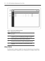
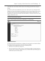


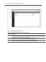


![PLAS A O ]-OR](http://vs1.manualzilla.com/store/data/005852706_1-5db0b7ed584537f0e62af161fb124638-150x150.png)