1
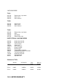
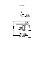
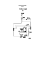
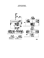
Cascade TEK
Division of Cascade Technical Sciences, Inc.
1800 NE 25TH Avenue ⋅ Hillsboro, OR 97124 ⋅ ℡ (503) 648-1818 ⋅ FAX: (503) 648-1798
This instruction manual applies to Models TFO-1, TFO-3, TFO-5, TFO-10, TFO-28,
TVO-1, TVO-2, and TVO-5
TABLE OF CONTENTS
SECTION 1.0
RECEIVING AND INSPECTION
SECTION 2.0
WARNING
SECTION 3.0
POWER SUPPLY
SECTION 4.0
INSTALLATION
SECTION 5.0
CONTROLS
SECTION 6.0
OPERATION
SECTION 7.0
PREVENTATIVE MAINTENANCE
SECTION 8.0
TROUBLE SHOOTING
SECTION 9.0
PART LISTS
SECTION 10.0
WARRANTY
REV 4/01
#4861477
AN INVITATION
Please take a few minutes to peruse this instruction manual before using your new oven. We want you to
be happy with the equipment, and use it safely. Please be sure that each person who uses the oven reads
the instructions.
1.0 RECEIVING AND INSPECTION
The carrier, when accepting shipment, also accepts responsibility for safe delivery, and is liable for loss or
damage claims. On delivery, you must inspect for visible exterior damage. Note and describe on the freight
bill any damage you find; then enter your claim on the form supplied by the carrier.
Inspect the oven for concealed damage. If you find any, the carrier will arrange for official inspection to
substantiate your claim.
Save the packing material until you're sure all is well. If, for any reason, you must return the oven, contact
your service representative; give the serial number, and request authorization for return. We want you to be
satisfied with your oven, and will be as helpful as possible.
2.0 WARNING
THIS IS NOT AN EXPLOSION-PROOF OVEN. Don't put anything in the oven that gives off combustible
vapors. Don't put combustible or flammable material in the oven. Be sure about this. Play it safe.
Don't put tightly sealed or filled containers in this or any other oven. The contents may expand and burst the
container.
This oven is not designed for use in Class I, II, or III locations as described in the National Electrical Code. It
is not intended, nor shall it be used as a patient-connected device as described in Article 517 of the National
Electrical Code.
3.0 POWER SUPPLY
A prime cause of poor oven performance is an inadequate power source. Before installing your oven,
inspect its proposed power supply. When the oven is operating at full draw, voltage at its terminals must be
no lower than 10% below its nameplate voltage and preferable no lower than 5% below.
The best arrangement, if at all possible, is to energize the oven from a receptacle that is on a branch circuit
of its own, no other receptacles being on the same branch. In the best installation, voltage at this receptacle
will drop no more than 5% when the oven is switched on full.
If you are using a receptacle that shares a branch circuit with several other receptacles, the oven may work
just fine until someone plugs a hot plate into one of the other receptacles. Then the circuit breaker may trip,
and the oven will go cold.
AVOID EXTENSION CORDS
Use of extension cords, particularly stringy, abraded ones are dangerous. They also cause added voltage
drop and violate most electrical codes. It is best not to use them at all.
POWER REQUIREMENTS
Note: 240-volt ovens may be operated on 208-volts. Heat-up will be slightly slower.
GROUND YOUR OVEN
Our 120-volt ovens are fitted with a power cord having a plug with grounding blade. Be sure the plug is used
with a matching receptacle and that the grounding blade is used. DO NOT cut off the grounding blade or
plug into a non-grounded receptacle. This would leave the oven's cabinet ungrounded in violation of
electrical codes and common sense.
If you have any doubts about receptacle grounding, have an electrician test the receptacle; making sure it is
correctly wired.
Some 240-volt ovens are set up to be hard wired. Have these models connected by a qualified person; and
make sure the oven grounding wire is connected to the equipment-grounding conductor in the branch circuit
feeding the oven.
4.0 INSTALL YOUR OVEN CAREFULLY
Location: Place your oven close to your power receptacle. Try to locate it away from drafts, air conditioners
and hot air ducts. Rapid changes in ambient temperature make it more difficult for the controller to hold
temperature at an exact level. This is true even though the controller is highly responsive.
Keep it Level: The oven has heavy-duty adjustable leveling legs. After you locate the chamber, use the legs
to level it.
Keep it Clean: The oven was thoroughly cleaned at the factory. But you might want to clean it again before
putting it to work. Then, from time to time, clean it when its walls or shelves get stained. Remove the
shelves. Clean them. Clean the entire interior, with particular attention to the corners.
5.0 KNOW THE CONTROLS
Power Switch: Turns the oven ON or OFF.
Overtemperature Safety: has a rotating knob allowing you to select the over temperature set point. To
operate, simply, turn the dial to the approximate desired temperature. Note: Scale is in °C and is ± 10°C.
RCOMMENDED OPERATION: Set the main oven temperature controller (per the instructions below) to your
desired oven set point. Allow the oven to stabilize at that set point. Turn the OTP knob to the left until the
safety light comes on. Back OTP knob off three to five degrees after the safety light goes off.
Temperature Controller: is a Watlow 981 programmable controller. Please refer to the controller manual
supplied with your oven for programming and more detailed information regarding your controller. For
simple set point information, turn to Paragraph 6.0. Before you operate the oven it would be a good idea to
turn to page 3.1 of the Watlow manual for a description of the key functions.
Vacuum Ovens: In addition to the controls listed above your vacuum oven has two additional controls.
Vacuum Inlet Valve: SMALL KNOB located to the left of the vacuum gauge. This knob allows is for venting
of the oven or use with an inert gas backfill. The connection for this valve is at the back of the oven and is
the smaller ¼” tube.
Vacuum Pump/Suction Valve: LARGE KNOB located just below the smaller vacuum inlet valve. This
knob opens the suction line that should be connected to the 3/8” tube located at the rear of the vacuum
oven. Disregard this connection if you intend to use the 1” vacuum/accessory port located in the center of
the back of the oven for your main vacuum connection.
Vacuum Gauge: Measures the vacuum level in the oven form 0 – 30” of vacuum.
6.0 HOW TO RUN THE OVEN
The following instructions are for single set point operations only. The Watlow 981 controller has 4 automatic
settable profiles with six steps within each profile. For programming and set-up instructions turn to Chapter 7
(page 7.1) in the Watlow manual supplied with your oven.
Set Point Operation: After the oven has been inspected and the proper power connection has been made,
follow the instructions below:
1.
Flip the power switch (located at the left of the instrument panel) It should glow with a green
light if it is connected to the power correctly.
2.
The Process (upper window on your Watlow 981controller) will display the current chamber
temperature.
3.
The lower window of your controller will indicate the current temperature set point.
4.
To increase the set point, press the up arrow key until the desired set point is displayed in
the lower controller window.
5.
To decrease the set point, press the down arrow key until the desired set point is displayed
in the lower controller window.
6.
The oven will heat to your selected set point and remain there until changed. Note: The set
point will not change even if the power is turned on and off.
Using the exhaust damper: If you want moderate ventilation in the oven, open the vent on top. The slide
damper controls volume of ventilation. Maximum flow will slightly increase heat up and recovery time.
7.0 PREVENTIVE MAINTENANCE
Disconnect the oven before servicing it.
A.
Remove the shelves. Clean the oven interior and shelves whenever they get stained or dirty.
B.
Inspect the door gasket, making sure it is in good condition, and that the door seals snugly against
its mullion.
C.
Level the oven, using its adjustable feet.
D.
If you suspect that air flow across the work space has decreased, have the blower wheel cleaned. It
is possible for the blower to get dirty if the oven is used with dirty, lint-laden loads.
E.
Run the oven at some usual temperature. Stabilize. Turn the overtemperature safety thermostat to a
temperature lower than that on the main temperature controller. Make sure the overtemperature
light comes on, and that oven temperature falls.
8.0 TROUBLE-SHOOTING
No Heat:
1.
The branch circuits serving the oven are dead.
2.
Oven cord plug is not in its receptacle.
3.
Oven power switch is open (off).
4.
The temperature controller is set too low.
5.
The overtemperature safety is set too low. It must be higher than the controller.
6.
The controller's Thermocouple temperature sensor is open circuited.
7.
The solid state relay is open circuited.
8.
Line contactors have failed open circuited. (Model TFO-28)
9.
The overtemperature safety has failed open circuited.
10.
A heater element has failed.
The Controller Calls For Heat Constantly:
1.
The controller's Thermocouple temperature sensor has failed. Oven temperature is now controlled
by the overtemperature safety.
2.
A solid state relay has failed closed. Temperature is now controlled by the overtemperature safety.
Blower Does Not Run (Heater Heats):
1.
Motor leads are disconnected at terminal blocks.
2.
Either the motor or blower wheel is jammed.
Blower Runs, But Air Volume is Reduced:
1.
Impeller and plenum are dirty.
9.0 PARTS LIST
FORCED AIR OVENS
PART NO.
DESCRIPTION
TFO-1
1800516
9570762
9600565
100056
4880512
600002
5120689
200129
DESCRIPTION
TFO-3
Power Cord
Element Assy.
Blower Motor Assy.
Blower Wheel 6 x 2
Blower Motor
Gasket 10 ft
Shelf
Adjustable Feet
TFO-5
101990
9570665
890081
9600565
100056
4880512
600002
5120691
200129
PART NO.
1800516
9570537
9600565
100056
4880512
600002
5120690
200129
Power Cord
Element Assy.
Blower Motor Assy.
Blower Wheel 6 x 2
Blower Motor
Gasket 10 ft
Shelf
Adjustable Feet
TFO-10
Power Cord
Element Assy.
Heating Element
Blower Motor Assy.
Blower Wheel 6 x 2
Blower Motor
Gasket 12 ft
Shelf
Adjustable Feet
9570679
9600562
100056
4880512
600002 .
5120888
2700500
Element Assy.
Motor Assy.
Motor Wheel 6 x 2
Motor
Gasket 12 ft
Shelf
Adjustable Feet
TFO-28
PARTS FOR ALL FORCED AIR OVENS
9570666
9600550
100056
4880512
600002
5120894
2700500
Element Assy.
Motor Assy.
Motor Wheel
Motor
Gasket 17 ft
Shelf
Adjustable Feet
1750571
102162
9650503
101827
200020
103351
4450506
200116
800542
101097
101098
1750540
200137
Thermostat 6’ Probe
Solid State Relay
Solid State Relay Assy.
TC Probe Closed End
Red Pilot Light
Green I/O Switch
Soft Touch Knob
Shelf Clips - Small
Terminal Block 18 Position
Power Exhaust 110V
Power Exhaust 220V
Watlow 981 Controller
Shelf Clips - Large
VACUUM OVENS
TVO-1
9570739
5620506
5620519
Element Assy., top / bottom
Shelf - Top 2
Shelf - Bottom 1
TVO-2
9570742
5620518
5620520
Element Assy.
Shelf - Top 2
Shelf - Bottom 1
TVO-5
9570765
5620523
5220580
9570764
Element Assy., top / bottom
Shelf
Shelf Sliders
Element Assy., side
PARTS FOR ALL VACUUM OVENS
9530535
9530536
100031
1800516
X1000771
103351
200020
8000542
100026
101827
1750540
102162
200129
Needle Valve Kit .250
Needle Valve Kit .375
Vacuum Gauge
Power Cord
Soft Touch Knob
Green I/O Switch
Red Pilot Light
Terminal Block 18 Position
Overtemperature Safety Thermostat
TC Probe Closed End
Watlow 981 Controller
Solid State Relay
Adjustable Feet
Gaskets for TVO’s
Silicone
HI-Temp Sill.
3450508
Viton
Acids
110085
Buna -N
Solvents
100049
TVO-1
100029
TVO-2
100037
3450509
100578
100038
TVO-5
310028
3450510
100233
891054
10.0 LIMITED WARRANTY
North America
Cascade TEK agrees to correct for the original user of this product, either by repair or at our election, by
replacement, any defect in material or workmanship which develop within twelve (12) months after delivery
of this product to the original user. In the event of replacement, replacement unit will be warranted for the
original twelve (12) month period or ninety (90) days, whichever is longer.
If this product should require service, contact Cascade TEK, Hillsboro, OR at (503) 648-1818. When return
of the product is necessary, a return authorization number will be assigned and the product should be
shipped, transportation charges pre-paid, to the service center. To insure prompt handling, the return
authorization number should be placed on the outside of the package and a detailed explanation of the
defect enclosed with the item.
This warranty shall not apply if accident, neglect, unreasonable use, improper service caused the defect or
malfunction, or other causes not arising out of defects in material or workmanship.
THERE ARE NO WARRANTIES, EXPRESS OR IMPLIED, INCLUDING, BUT NOT LIMITED TO, THOSE
MERCHANTABILITY OR FITNESS FOR A PARTICULAR PURPOSE, WHICH EXTEND BEYOND THE
DESCRIPTION AND PERIOD SET FORTH HEREIN.
Cascade TEK'S SOLE OBLIGATION UNDER THIS WARRANTY IS LIMITED TO THE REPAIR OR
REPLACEMENT OF A DEFECTIVE PRODUCT AND Cascade TEK SHALL NOT, IN ANY EVENT, BE
LIABLE FOR ANY ACCIDENTAL OR CONSEQUENTIAL DAMAGES OF ANY KIND RESULTING FROM
USE OR POSSESSION OF THE PRODUCT.
Export
The Cascade TEK warranty for all equipment delivered outside the continental US or Canada is 1 year on
defective parts. The purchaser will be responsible for all labor costs for on-site repairs or parts installation.
All replacement parts provided under warranty by Cascade TEK are shipped F.O.B. our plant in Hillsboro
Oregon.
WIRING DIAGRAM
TFO-1, TFO-3
WIRING DIAGRAM
TFO-5
WIRING DIAGRAM
TFO-10
WIRING DIAGRAM
TFO-28
WIRING DIAGRAM
TVO-1, TVO-2, TVO-5