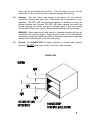
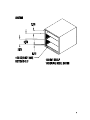
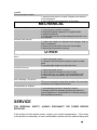
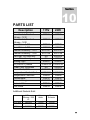
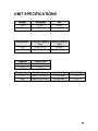
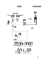
1
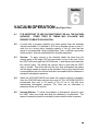
VACUUM
OVEN
MODEL: 1410,1430
INSTALLATION AND OPERATIONAL MANUAL
Sheldon Manufacturing Inc. P.O. Box 627 Cornelius, Oregon 97113
EMAIL: [email protected] INTERNET: http://www.Shellab.com/~Shellab
1-800-322-4897
(503) 640-3000
FAX (503) 640-1366
TABLE OF CONTENTS
SECTION 1.0
RECEIVING AND INSPECTION
SECTION 2.0
GRAPHIC SYMBOLS
SECTION 3.0
INSTALLATION
SECTION 4.0
CONTROL PANEL OVERVIEW
SECTION 5.0
PRECAUTIONS
SECTION 6.0
VACUUM OPERATION
SECTION 7.0
OPERATION
SECTION 8.0
MAINTENANCE
SECTION 9.0
TROUBLESHOOTING AND SERVICE
SECTION 10.0
PARTS LIST
UNIT SPECIFICATIONS
SCHEMATICS
REV. 02/07
4861262
These units are general purpose vacuum ovens for professional, industrial or educational
use where the preparation or testing of materials is done at approximately atmospheric
pressure and no flammable, volatile or combustible materials are being heated. These
units are not intended for hazardous or household locations or use.
2
1
Section
RECEIVING AND INSPECTION
Your satisfaction and safety require a complete understanding of this unit. Read
the instructions thoroughly and be sure all operators are given adequate training
before attempting to put the unit in service. NOTE: This equipment must be used
only for its intended application; any alterations or modifications will void your
warranty.
1.1
Inspection: The carrier, when accepting shipment, also accepts responsibility
for safe delivery and is liable for loss or damage. On delivery, inspect for visible
exterior damage, note and describe on the freight bill any damage found, and
enter your claim on the form supplied by the carrier.
1.2
Inspect for concealed loss or damage on the unit itself, both interior and exterior.
If necessary, the carrier will arrange for official inspection to substantiate your
claim.
1.3
Return Shipment: Save the shipping crate until you are sure all is well. If for
any reason you must return the unit, first contact your customer representative
for authorization. Supply nameplate data, including model number and serial
number. Please see the manual cover for information on where to contact
customer service.
1.4
Accessories: Verify that all of the equipment indicated on the packing slip is
included with the unit. Carefully check all packaging before discarding. These
units are equipped with 2 shelves and a thermometer. The 1430 comes with 4
leveling feet.
3
2
Section
GRAPHIC SYMBOLS
Your oven has been provided with a display of graphic symbols which should help in
identifying the use and function of the available user adjustable components.
2.1
Indicates "AC Power On".
2.2
Indicates "I/O" (ON/OFF).
2.3
Indicates "Vacuum Gauge".
2.4
Indicates "Vent (Gas)".
2.5
Indicates "Vacuum".
2.6
Indicates "Adjustable Temperature".
2.7
Indicates "Manual Adjust".
2.8
Indicates "Heating".
2.9
Indicates "Consult Your Manual".
2.10
Indicates “Unit should be recycled” (Not disposed of in
land-fill)
4
3
Section
INSTALLATION (See Figure One)
Local city, county or other ordinances may govern the use of this equipment. If you
have any questions about local requirements, please contact the appropriate local
agency. Installation may be performed by the end user.
Under normal circumstances this unit is intended for use indoors, at room temperatures
between 5° and 40°C, at no greater than 80% Relative Humidity (at 25°C) and with a
supply voltage that does not vary by more than 10%. Customer service should be
contacted for operating conditions outside of these limits.
3.1
Power Source: The electrical supply circuit to the oven must conform to all
national and local electrical codes. Consult the oven’s serial data plate for the
voltage, and ampere requirements before making connection. VOLTAGE
SHOULD NOT VARY MORE THAN 10% FROM THE SERIAL PLATE RATING.
This unit is intended for 50/60 Hz application. A separate circuit is recommended
to prevent possible loss of product due to overloading or failure of other
equipment on the same circuit.
3.2
Location: When selecting a site for the oven, consider all conditions which may
affect performance, such as extreme heat from steam radiators, stoves, ovens,
autoclaves, etc. Avoid direct sun, fast-moving air currents, heating/cooling ducts,
and high traffic areas. To ensure air circulation around the unit allow a minimum
of 30 cm between the unit and walls or partitions which might obstruct free
airflow.
3.3
Lifting / Handling: These units are heavy and care should be taken to use
appropriate lifting devices that are sufficiently rated for these loads. Units should
only be lifted from their bottom surfaces. Doors, handles and knobs are not
adequate for lifting or stabilization. The unit should be completely restrained
from tipping during lifting or transport. All moving parts, such as shelves and
trays should be removed and doors need to be positively locked in the closed
position during transfer to prevent shifting and damage.
3.4
Leveling: The unit must sit level and solidly. The Model 1410 has four rubber
feet that are already attached to the unit and are not adjustable. Leveling feet
are supplied with Model 1430 and must be installed in the four holes in the
bottom corners of the unit. With the unit standing upright, turn the leveling feet
counterclockwise to raise the level of that corner. Adjust the leveling foot at each
5
corner until the unit stands solid and level. If the unit must be moved, turn the
leveling feet in all the way (clockwise) to prevent damage while moving.
3.5
Cleaning: The oven interior was cleaned at the factory, but not sterilized.
Remove all shelving and clean with a disinfectant that is appropriate to your
application. DO NOT USE chlorine-based bleaches or abrasives as they will
damage stainless steel surfaces. DO NOT USE spray cleaners that might leak
through openings and cracks and get on electrical parts or that may contain
solvents that will harm the coatings. A similar periodic cleaning is recommended.
WARNING: Never clean the unit with alcohol or flammable cleaners with the unit
connected to the electrical supply. Always disconnect the unit form the electrical
service when cleaning and assure all volatile or flammable cleaners are evaporated
and dry before reattaching the unit to the power supply.
3.6
Shelves: See FIGURE ONE for proper orientation of shelves within specific
chamber. DO NOT place items directly on the floor of the chamber.
FIGURE ONE
6
7
4
Section
CONTROL PANEL OVERVIEW (See Figure Two)
4.1
POWER: The main power I/O (ON/OFF) switch must be in the I/On position
before any electrical systems are optional.
4.2
HEATING: This pilot lamp is on when the temperature controller has activated
the heating elements to reach and maintain set point.
4.3
TEMPERATURE CONTROLLER: This is the manually adjustable temperature
controller marked SET TEMPERATURE. Its dial is marked from 0 to 10 and is
adjustable across this scale. A clockwise adjustment raises the temperature.
4.4
VACUUM: This adjustment valve, located on the right of the panel, allows
opening and closing of the piping system to an external vacuum pump or system.
4.5
VENT: This adjustment valve, located on the left of the panel, controls the
vacuum release to return the chamber to atmospheric pressure.
4.6
VACUUM GAUGE: This component indicates the chamber operating pressure
in inches of mercury.
8
FIGURE TWO
9
5
Section
PRECAUTIONS
THIS IS NOT AN EXPLOSION PROOF OVEN.
5.1
Do not place or use explosive, combustible, or flammable materials in the
oven.
5.2
Do not use sealed containers in the oven chamber.
5.3
Do not cut or remove the ground prong from the power cord or use an
ungrounded 2-prong adapter plug.
5.4
Disconnect the unit from the electrical power source before attempting to
make any repairs or component replacements.
5.5
If a mercury thermometer is used and breakage should occur, all spilled
mercury must be completely removed from the chamber.
5.6
THIS OVEN IS NOT SUITABLE FOR USE IN CLASS I, II, OR III
LOCATIONS AS DEFINED BY THE NATIONAL ELECTRICAL CODE
NFPA 70.
5.7
This oven is not intended, nor can it be used, as a patient connected device.
10
6
Section
VACUUM OPERATION (See Figure Two)
6.1
IT IS IMPORTANT TO USE VACUUM TUBING FOR ALL THE VACUUM
HOOKUPS.
OTHER TYPES OF TUBING MAY COLLAPSE AND
PREVENT COMPLETE EVACUATION.
6.2
A pump with a pumping capacity four times greater than the chamber
volume is advisable. For example a 1410 has a chamber volume of one (1)
cubic foot so a pump with a pumping capacity of four (4) cubic feet per
minute is recommended. When working below 1mm, a diffusion type pump
will be needed. See unit specifications for chamber capacities.
6.3
Vacuum: To apply vacuum to the chamber attach the hose from the
vacuum pump to the larger 3/8" hose connection on top of the oven. Close
the VENT valve and open the VACUUM valve. Latch the door shut and start
the vacuum pump. Be certain the vacuum valve is open and the VENT
valve is closed. This action will hold the door shut and against the gasket
until the pump creates a vacuum in the chamber. Once a good vacuum seal
is accomplished, the door will hold itself shut and sealed until the chamber is
returned to atmospheric pressure.
6.4
Watch the VACUUM GAUGE and when the required vacuum is obtained,
close the VACUUM valve and turn the pump off. The VACUUM GAUGE is
incremented from zero to 30 inches of Hg (76 cm of Hg) with zero
representing atmospheric pressure. The oven can be evacuated to
pressures as low as 10 microns.
6.5
Vacuum Release: To return the chamber to atmospheric pressure, open
the VENT valve very slowly and allow the chamber to re-pressurize. The
speed of pressurizing can be controlled by how much the valve is opened.
11
7
Section
OPERATION
NOTE: Slight vapor or smoke may occur in the initial heat-up. This is the
dissipation of protective coatings that have been applied to the oven
elements.
7.1
Power Supply: Connect the service cord to a grounded outlet and push the
power switch to the I/ON position. If supplied with a detachable cordset,
plug the female end into the inlet of the unit and the male plug into the
supply. Assure that units requiring a fuse have a fuse installed. This fuse
may be at the inlet or part of the cordset male plug.
7.2
Place a reference thermometer inside the chamber where it can be easily
viewed through the window. Then vacuum down the chamber as described
in Section 6.0
7.3
Setting Temperature: The temperature control dial is marked from 0-10.
These scale numbers do not represent temperature but are to be used as a
reference guide. The operating range is 40°C - 200°C. The dial should be
used according to the operating range. To set the temperature control, turn
the knob clockwise to the setting on the dial that is just above the
approximate operating temperature desired. The HEATING light will come
on indicating that the oven is heating. Allow the unit to heat until the
reference thermometer has reached the desired temperature. When the
desired temperature has been reached, turn the control knob
counterclockwise just until the HEATING light goes off. Allow the unit to
stabilize for several hours. Re-adjust the control knob up or down as
required until the desired temperature is obtained. Allow the unit to stabilize
between each setting. Temperature stability is obtained when the HEATING
light circulates on and off to maintain set point and the temperature value in
the chamber remains consistent.
12
8
Section
MAINTENANCE
NOTE: Prior to any maintenance or service on this unit, disconnect the service
cord from the power supply.
8.1
Cleaning: Disinfect the oven interior on a regular basis. To prepare the
oven for cleaning remove the shelves and door gasket. The shelves and
door gasket are autoclavable.
A. First clean removed parts and interior with soap and water. To
decontaminate use a disinfectant that is suitable to your
application.
DO NOT use chlorine based bleaches or
abrasives as this will damage stainless steel surfaces.
B.
When washing the gasket, handle carefully so as not to impair
the positive seal.
8.2
If the oven is to be shut down for storage or transporting, remove shelves
and latch the door closed. Screw the leveling feet in on the 1430. See
Section 3.3 for transport procedures.
8.3
There is no maintenance required on the electrical components. If the oven
fails to operate as specified, see Troubleshooting before calling for service.
13
9
Section
TROUBLESHOOTING
Always make a visual inspection of the oven and control console when troubleshooting.
Look for loose or disconnect wires or tubing, which may be the source of the trouble.
The oven is designed so that no internal electrical servicing should be required under
normal conditions. If electrical servicing is necessary, it should be performed by
qualified service personnel.
TEMPERATURE
Temperature too high
1/ controller set too high-see Section 7.3
2/ controller failed on – call Customer Service
3/ wiring error – call Customer Service
Temperature too low
3/ controller set too low – see section 7.3
4/ unit not recovered from door opening – wait for display to
stop changing
5/ unit not recovered from power failure or being turned off
6/ element failure – see if heating light is on; compare
current draw to data plate
7/ controller failure – confirm with front panel lights that
controller is calling for heat
8/ if ambient room temperature is lower than range of unit –
compare set points and ambient temperature to rated
specifications in manual Unit Specifications
9/ wiring problem – check all functions and compare wiring
to wiring schematic in manual - especially around any areas
recently worked on
10/ loose connection – check shadow box for loose
connections
Unit will not heat up at all
1/ verify that controller is asking for heat by looking for
heating light – if pilot light is not on continuously during initial
start up, there is a problem with the controller
2/ check amperage – amperage should be virtually at
maximum rated (data plate) amperage
3/ UNITS WILL NEED AT LEAST SOME VACUUM IN
CHAMBER TO KEEP UNIT AIR TIGHT - VERIFY WITH
CONTROL PANEL VACUUM GAGE
Indicated chamber temperature
14
unstable
Will not maintain set point
1/ assure that set point is at least 5 degrees over ambient
room temperature
2/ see if ambient room temperature is fluctuating
MECHANICAL
door not sealing
1/ check physical condition of gasket
2/ assure that gasket clamps are in original location
3/ adjust hinge blocks
4/ Confirm that unit has not been damaged and body is not
out of square.
unit won’t hold vacuum
1/ check door gasket for alignment and damage, wear or
lack of compliance
2/ assure all vent and feed valves are closed tightly
3/ assure tight connections to pump
OTHER
unit or wall fuse/circuit breaker is
blown
1/ check wall power source
2/ compare current draw and compare to specs on data
plate
3/ see what other loads are on the wall circuit
unit will not turn on
1/ check wall power source
2/ check fuse/circuit breaker on unit or in wall
3/ see if unit is on, e.g., heater, and just controller is off
4/ check all wiring connections, esp. around the on/off
switch
Unit is smoking – Out of box
This is not uncommon during initial operation. Put unit under
vent and run at full power for one hour.
Contamination in chamber
1/ see cleaning procedure in operator’s manual
2/ develop and follow standard operating procedure for
specific application; include definition of cleaning technique
and maintenance schedule
SERVICE
FOR PERSONAL SAFETY, ALWAYS DISCONNECT THE POWER BEFORE
SERVICING.
If this product should require service, contact your service representative. If the return
of the product be necessary, a return authorization number must be obtained along with
15
proper shipping instructions. To insure prompt handling, the return authorization
number should be placed on the outside of the package or container. Make sure a
detailed explanation of the reason for return is enclosed with the unit. For information
on where to contact customer service, please see the manual cover.
16
Section
10
PARTS LIST
Description
115V
220V
Door Gasket, Standard
Silicone - 1410
Door Gasket, Standard
Silicone - 1430
Door Glass - 1410
Door Glass - 1430
Element Assembly - 1410
Element Assembly - 1430
EMI Filter, CE units only
Fuse, CE units only
Heating Light
I/O (ON/OFF) Switch
Power Cord, European
Power Cord, USA
Temperature Control Knob
Temperature Controller
Thermometer
Vacuum Gauge
Vacuum Valve
Vent Valve
100029
100029
100037
100037
700027
110107
9570741
9570728
NA
NA
200020
X1000124
NA
1800516
X1000771
100026
100030
3500509
700028
100032
700027
110107
9570741
9570728
2800502
103555
200020
X1000124
1800500
101990
X1000771
100026
100030
3500509
700028
100032
Additional Gaskets Sold:
Hi-Temp
Silicone > 250
°C
1410 size
3450508
Viton
Acids
Buna
Solvents
110085
100049
1430 size
100578
100038
3450509
17
UNIT SPECIFICATIONS
Weight
Shipping
Net
1410
67 lbs.
55 lbs.
1430
170 lbs.
115 lbs.
Dimensions
Exterior WxDxH
(in.)
Interior WxDxH
(in.)
1410
20.5x17x16.3
9x12x9
1430
23.8x26.3x20.3
12x20x12
Capacity
Cubic Feet
1410
1430
0.6
1.7
Temperature
Range
Uniformity
Sensitivity
1410
Amb.+ 5° to 200°C
2.0° @ 100°C
1.0°C
1430
Amb.+ 5° to 200°C
3.0° @ 100°C
1.0°C
18
WIRE
DIAGRAM
19
SHELDON MANUFACTURING, INC.
LIMITED WARRANTY
Sheldon Manufacturing, Inc., (“Manufacturer”) warrants for the original user of this product in the U.S.A. only that this product (parts only
if outside of the U.S.A.) will be free from defects in material and workmanship for a period of two years from the date of delivery of this
product to the original user (the “Warranty Period”). During the Warranty Period, Manufacturer, at its election and expense, will repair or
replace the product or parts that are proven to Manufacturer’s satisfaction to be defective, or, at Manufacturer’s option, refund the price or
credit (against the price of future purchases of the product) the price of any products that are proven to Manufacturer’s satisfaction to be
defective. This warranty does not include any labor charges if outside of the U.S.A. This warranty does not cover any damage due to
accident, misuse, negligence, or abnormal use. Use of Manufacturer’s product in a system that includes components not manufactured by
Manufacturer is not covered by this warranty. This warranty is void in the event that repairs are made by anyone other than Manufacturer
without prior authorization from Manufacturer. Any alteration or removal of the serial number on Manufacturer’s products will void this
warranty. Under no circumstances will Manufacturer be liable for indirect, incidental, consequential, or special damages. The
terms of this warranty are governed by the laws of the state of Oregon without regards to the principles of conflicts of laws thereof. If any
provision of this limited warranty is held to be unenforceable by any court of competent jurisdiction, the remainder of this limited warranty
will remain in full force and effect.
This warranty is in lieu of and excludes all other warranties or obligations, either express or implied. Manufacturer expressly
disclaims all implied warranties, including without limitation, the warranties of merchantability and fitness for a particular
purpose.
For fast and efficient support, please have the following information available anytime you request service:
Model
__________
Serial No. __________
Part No.
__________
20
ORDER FROM VWR
Call 800-932-5000
from anywhere in the U.S. and Canada
Sales & Inventory Locations:
Pacific Northwest Are Midwest Area
Anchorage, A K
Salt Lake City, UT
San Francisco, CA
Seattle, WA
Tualatin, OR
Chicago, IL
Detroit, MI
Indianapolis, IN
Minneapolis, MN
St. Louis, MO
Southwest Area
Albuquerque, NM
Denver, CO
Phoenix, AZ
San Diego, CA
S A N
D I M A S ,
Gulf Area
Austin, TX
Dallas, TX
Houston, TX
Lake Charles, LA
Northeast Area
Southeast Area
Boston, MA
Cincinnati, OH
Cleveland, OH
Pittsburgh, PA
Rochester, NY
Atlanta, GA
Oak Ridge, TN
Mid-Atlantic Area
VWR Canlab Offices
Baltimore, MD
Branford, CT
Bridgeport, NJ
S. Plainfield, NJ
Mississauga, Ontario
Ville Mont-Royal, Québec
Edmonton, Alberta
C A
Or Call Direct for Specialized Service Locations:
VWR International
3000 Hadley Rd
S. Plainfield, NJ 07080
(908) 757-4045
fax: (908) 757-0313
Puerto Rico
Carr. #869 Km. 1.5 M4
Royal Industrial Park
Catano, PR 00962
(787) 788-3222
fax: (787) 78804320
Switzerland
Ruchligstrasse # 20
P.O. Box 464
Dietikon, Switzerland
CH-8953
011-41-1-745-1155
fax: 011-41-1-745-1150
VWR Direct
VWR Furniture Division
P.O. Box 3405
Irving, TX 75015
(972) 714-0336
VWR National Accounts
1310 Goshen Pkwy
W. Chester, PA 19380
(610) 431-1700
911 Commerce Ct.
Buffalo Grove, IL 60089
(800) 444-0880
Visit Our Web Site at
http://www.vwrsp.com
F:\manuals\vwr back sheet.doc