1
48TCA04---A12
Nominal 3 to 10 Tons
With Puron® (R---410A) Refrigerant
Service and Maintenance Instructions
TABLE OF CONTENTS
SAFETY CONSIDERATIONS
SAFETY CONSIDERATIONS . . . . . . . . . . . . . . . . . . . . 1
Installation and servicing of air-conditioning equipment
can be hazardous due to system pressure and electrical
components. Only trained and qualified service personnel
should install, repair, or service air-conditioning
equipment. Untrained personnel can perform the basic
maintenance functions of replacing filters. Trained service
personnel should perform all other operations.
UNIT ARRANGEMENT AND ACCESS . . . . . . . . . . . 2
SUPPLY FAN (BLOWER) SECTION . . . . . . . . . . . . . . 4
COOLING . . . . . . . . . . . . . . . . . . . . . . . . . . . . . . . . . . . . 5
PURONR (R-- 410A) REFRIGERANT . . . . . . . . . . . . . . 8
COOLING CHARGING CHARTS . . . . . . . . . . . . . . . . . 9
CONVENIENCE OUTLETS . . . . . . . . . . . . . . . . . . . . 14
SMOKE DETECTORS . . . . . . . . . . . . . . . . . . . . . . . . . 15
PROTECTIVE DEVICES . . . . . . . . . . . . . . . . . . . . . . . 22
GAS HEATING SYSTEM . . . . . . . . . . . . . . . . . . . . . . 22
PREMIERLINKT CONTROL . . . . . . . . . . . . . . . . . . . 34
RTU-- MP CONTROL SYSTEM . . . . . . . . . . . . . . . . . . 42
ECONOMI$ER SYSTEMS . . . . . . . . . . . . . . . . . . . . . . 55
WIRING DIAGRAMS . . . . . . . . . . . . . . . . . . . . . . . . . 63
PRE-- START-- UP . . . . . . . . . . . . . . . . . . . . . . . . . . . . . . 66
START-- UP, GENERAL . . . . . . . . . . . . . . . . . . . . . . . . 66
START-- UP, PREMIERLINKT CONTROL . . . . . . . . 68
START-- UP, RTU-- MP CONTROL . . . . . . . . . . . . . . . . 68
OPERATING SEQUENCES . . . . . . . . . . . . . . . . . . . . . 71
FASTENER TORQUE VALUES . . . . . . . . . . . . . . . . . 81
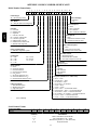
APPENDIX I. MODEL NUMBER SIGNIFICANCE . 82
APPENDIX II. PHYSICAL DATA . . . . . . . . . . . . . . . . 83
APPENDIX III. FAN PERFORMANCE . . . . . . . . . . . 87
APPENDIX IV. ELECTRICAL DATA . . . . . . . . . . . . . 99
APPENDIX V. WIRING DIAGRAM LIST . . . . . . . . 104
APPENDIX VI. MOTORMASTER SENSOR
LOCATIONS . . . . . . . . . . . . . . . . . . . . . . . . . . . . . . . . 105
UNIT START-UP CHECKLIST . . . . . . . . . . . . . . . . . 107
When working on air-conditioning equipment, observe
precautions in the literature, tags and labels attached to
the unit, and other safety precautions that may apply.
Follow all safety codes. Wear safety glasses and work
gloves. Use quenching cloth for unbrazing operations.
Have fire extinguishers available for all brazing
operations.
Follow all safety codes. Wear safety glasses and work
gloves. Use quenching cloth for brazing operations. Have
fire extinguisher available. Read these instructions
thoroughly and follow all warnings or cautions attached to
the unit. Consult local building codes and National
Electrical Code (NEC) for special requirements.
Recognize safety information. This is the safety-- alert
. When you see this symbol on the unit and in
symbol
instructions or manuals, be alert to the potential for
personal injury.
Understand the signal words DANGER, WARNING, and
CAUTION. These words are used with the safety-- alert
symbol. DANGER identifies the most serious hazards
which will result in severe personal injury or death.
WARNING signifies a hazard which could result in
personal injury or death. CAUTION is used to identify
unsafe practices which may result in minor personal
injury or product and property damage. NOTE is used to
highlight suggestions which will result in enhanced
installation, reliability, or operation.
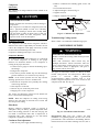
WARNING
48TC
!
FIRE, EXPLOSION HAZARD
Failure to follow this warning could result in
personal injury, death and/or property damage.
Refer to the User’s Information Manual provided
with this unit for more details.
Do not store or use gasoline or other flammable
vapors and liquids in the vicinity of this or any other
appliance.
What to do if you smell gas:
DO NOT try to light any appliance.
DO NOT touch any electrical switch, or use any
phone in your building.
IMMEDIATELY call your gas supplier from a
neighbor’s phone. Follow the gas supplier’s
instructions.
If you cannot reach your gas supplier, call the fire
department.
!
WARNING
!
WARNING
FIRE, EXPLOSION HAZARD
Failure to follow this warning could result in personal
injury or death.
Disconnect gas piping from unit when pressure testing
at pressure greater than 0.5 psig. Pressures greater
than 0.5 psig will cause gas valve damage resulting in
hazardous condition. If gas valve is subjected to
pressure greater than 0.5 psig, it must be replaced
before use. When pressure testing field-supplied gas
piping at pressures of 0.5 psig or less, a unit connected
to such piping must be isolated by closing the manual
gas valve(s).
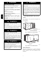
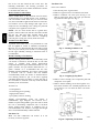
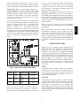
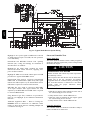
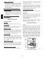
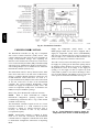
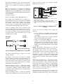
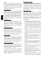
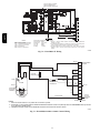
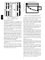
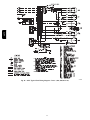
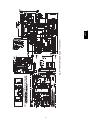
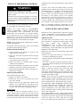
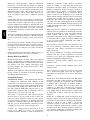
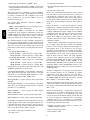
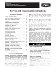
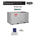
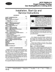
UNIT ARRANGEMENT AND ACCESS
General
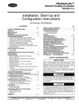
Fig. 1 and Fig. 2 show general unit arrangement and
access locations.
FILTER ACCESS PANEL
ELECTRICAL OPERATION HAZARD
Failure to follow this warning could result in personal
injury or death.
Before performing service or maintenance operations
on unit, turn off main power switch to unit. Electrical
shock and rotating equipment could cause injury.
!
COMPRESSOR
ACCESS PANEL (04-07 only)
WARNING
OUTDOOR-AIR OPENING AND
INDOOR COIL ACCESS PANEL
ELECTRICAL OPERATION HAZARD
Failure to follow this warning could result in personal
injury or death.
Units with convenience outlet circuits may use
multiple disconnects. Check convenience outlet for
power status before opening unit for service. Locate
its disconnect switch, if appropriate, and open it.
Tag-- out this switch, if necessary.
!
Fig. 1 - Typical Access Panel Locations
WARNING
UNIT OPERATION AND SAFETY HAZARD
Failure to follow this warning could cause personal
injury, death and/or equipment damage.
Puron (R-- 410A) refrigerant systems operate at higher
pressures than standard R-- 22 systems. Do not use
R-- 22 service equipment or components on Puron
refrigerant equipment.
C08449
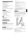
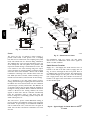
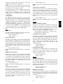
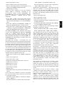
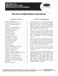
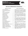
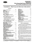
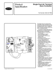
BLOWER
ACCESS
PANEL
CONTROL BOX
COMPRESSOR
(08-12 only)
Fig. 2 - Blower Access Panel Location
C08450
Routine Maintenance
These items should be part of a routine maintenance
program, to be checked every month or two, until a
specific schedule for each can be identified for this
installation:
2
Seasonal Maintenance
These items should be checked at the beginning of each
season (or more often if local conditions and usage
patterns dictate):
Air Conditioning
S Condenser fan motor mounting bolts tightness
S Compressor mounting bolts
S Condenser fan blade positioning
S Control box cleanliness and wiring condition
S Wire terminal tightness
S Refrigerant charge level
S Evaporator coil cleaning
S Evaporator blower motor amperage
Heating
S Heat exchanger flue passageways cleanliness
S Gas burner condition
S Gas manifold pressure
S Heating temperature rise
Economizer or Outside Air Damper
S Inlet filters condition
S Check damper travel (economizer)
S Check gear and dampers for debris and dirt
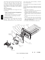
Air Filters and Screens
To remove the filters:
1. Grasp the bottom flange of the upper panel.
2. Lift up and swing the bottom out until the panel disengages and pulls out.
3. Reach inside and extract the filters from the filter
rack.
4. Replace these filters as required with similar replacement filters of same size.
To re-- install the access panel:
1. Slide the top of the panel up under the unit top panel.
2. Slide the bottom into the side channels.
3. Push the bottom flange down until it contacts the top
of the lower panel (or economizer top).
IMPORTANT: DO NOT OPERATE THE UNIT
WITHOUT THESE FILTERS!
Outside Air Hood
Outside air hood inlet screens are permanent
aluminum-- mesh type filters. Check these for cleanliness.
Remove the screens when cleaning is required. Clean by
washing with hot low-- pressure water and soft detergent
and replace all screens before restarting the unit. Observe
the flow direction arrows on the side of each filter frame.
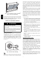
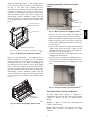
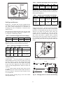
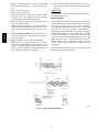
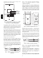
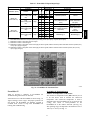
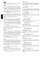
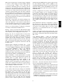
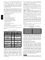
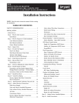
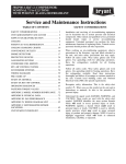
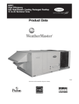
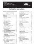
Economizer Inlet Air Screen
This air screen is retained by spring clips under the top
edge of the hood. (See Fig. 3.)
17 1/4”
DIVIDER
OUTSIDE
AIR
HOOD
Each unit is equipped with return air filters. If the unit has
an economizer, it will also have an outside air screen. If a
manual outside air damper is added, an inlet air screen
will also be present.
CLEANABLE
ALUMINUM
FILTER
BAROMETRIC
RELIEF
Each of these filters and screens will need to be
periodically replaced or cleaned.
FILTER
CLIP
Return Air Filters
Return air filters are disposable fiberglass media type.
Access to the filters is through the small lift-- out panel
located on the rear side of the unit, above the
evaporator/return air access panel. (See Fig. 1.)
FILTER
Fig. 3 - Filter Installation
C06027
To remove the filter, open the spring clips. Re-- install the
filter by placing the frame in its track, then closing the
spring clips.
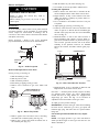
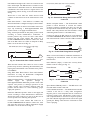
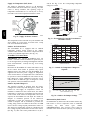
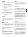
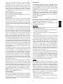
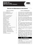
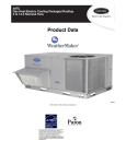
Manual Outside Air Hood Screen
This inlet screen is secured by a retainer angle across the
top edge of the hood. (See Fig. 4.)
3
48TC
Quarterly Inspection (and 30 days after initial start)
S Return air filter replacement
S Outdoor hood inlet filters cleaned
S Belt tension checked
S Belt condition checked
S Pulley alignment checked
S Fan shaft bearing locking collar tightness checked
S Condenser coil cleanliness checked
S Condensate drain checked
inside surfaces. Check belt tension by using a spring-- force
tool (such as Browning’s Part Number “Belt Tension
Checker” or equivalent tool); tension should be 6-- lbs at a
5/8-- in. deflection when measured at the centerline of the
belt span. This point is at the center of the belt when
measuring the distance between the motor shaft and the
blower shaft.
NOTE: Without the spring-- tension tool, place a straight
edge across the belt surface at the pulleys, then deflect the
belt at mid-- span using one finger to a 1/2-- in. deflection.
C07156
48TC
Fig. 4 - Screens Installed on Outdoor-- Air Hood
(Sizes 7-- 1/2 to 12-- 1/2 Tons Shown)
To remove the screen, loosen the screws in the top retainer
and slip the retainer up until the filter can be removed.
Re-- install by placing the frame in its track, rotating the
retainer back down and tighten all screws.
SUPPLY FAN (BLOWER) SECTION
!
WARNING
ELECTRICAL SHOCK HAZARD
Failure to follow this warning could cause personal
injury or death.
Before performing service or maintenance operations
on the fan system, shut off all unit power and tag-- out
the unit disconnect switch. Do not reach into the fan
section with power still applied to unit.
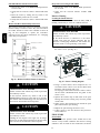
Supply Fan (Belt--Drive)
The supply fan system consists of a forward-- curved
centrifugal blower wheel on a solid shaft with two
concentric type bearings, one on each side of the blower
housing. A fixed-- pitch driven pulley is attached to the fan
shaft and an adjustable-- pitch driver pulley is on the
motor. The pulleys are connected using a “V” type belt.
(See Fig. 5.)
Adjust belt tension by loosening the motor mounting plate
front bolts and rear bolt and sliding the plate toward the
fan (to reduce tension) or away from fan (to increase
tension). Ensure the blower shaft and the motor shaft are
parallel to each other (pulleys aligned). Tighten all bolts
when finished.
To replace the belt:
1. Use a belt with same section type or similar size. Do
not substitute a “FHP” type belt. When installing the
new belt, do not use a tool (screwdriver or pry-- bar) to
force the belt over the pulley flanges, this will stress
the belt and cause a reduction in belt life.
2. Loosen the motor mounting plate front bolts and rear
bolts.
3. Push the motor and its mounting plate towards the
blower housing as close as possible to reduce the center distance between fan shaft and motor shaft.
4. Remove the belt by gently lifting the old belt over
one of the pulleys.
5. Install the new belt by gently sliding the belt over
both pulleys and then sliding the motor and plate
away from the fan housing until proper tension is
achieved.
6. Check the alignment of the pulleys, adjust if necessary.
7. Tighten all bolts.
8. Check the tension after a few hours of runtime and
re-- adjust as required.
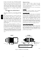
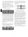
Adjustable-- Pitch Pulley on Motor
The motor pulley is an adjustable-- pitch type that allows a
servicer to implement changes in the fan wheel speed to
match as-- installed ductwork systems. The pulley consists
of a fixed flange side that faces the motor (secured to the
motor shaft) and a movable flange side that can be rotated
around the fixed flange side that increases or reduces the
pitch diameter of this driver pulley. (See Fig. 6.)
As the pitch diameter is changed by adjusting the position
of the movable flange, the centerline on this pulley shifts
laterally (along the motor shaft). This creates a
requirement for a realignment of the pulleys after any
adjustment of the movable flange. Also reset the belt
tension after each realignment.
Fig. 5 - Belt Drive Motor Mounting
C07087
Belt
Check the belt condition and tension quarterly. Inspect the
belt for signs of cracking, fraying or glazing along the
Check the condition of the motor pulley for signs of wear.
Glazing of the belt contact surfaces and erosion on these
surfaces are signs of improper belt tension and/or belt
slippage. Pulley replacement may be necessary.
4
Motor
1. Shut off unit power supply.
2. Loosen belt by loosening fan motor mounting nuts.
(See Fig. 5.)
3. Loosen movable pulley flange setscrew. (See Fig. 6.)
4. Screw movable flange toward fixed flange to increase
speed and away from fixed flange to decrease speed.
Increasing fan speed increases load on motor. Do not
exceed maximum speed specified.
5. Set movable flange at nearest keyway of pulley hub
and tighten setscrew to torque specifications.
To align fan and motor pulleys:
1. Loosen fan pulley setscrews.
2. Slide fan pulley along fan shaft. Make angular alignment by loosening motor from mounting.
3. Tighten fan pulley setscrews and motor mounting
bolts to torque specifications.
4. Recheck belt tension.
When replacing the motor, also replace the external-- tooth
lock washer (star washer) under the motor mounting base;
this is part of the motor grounding system. Ensure the
teeth on the lock washer are in contact with the motor’s
painted base. Tighten motor mounting bolts to 120 +/-- 12
in-- lbs.
Changing fan wheel speed by changing pulleys: The
horsepower rating of the belt is primarily dictated by the
pitch diameter of the smaller pulley in the drive system
(typically the motor pulley in these units). Do not install a
replacement motor pulley with a smaller pitch diameter
than provided on the original factory pulley. Change fan
wheel speed by changing the fan pulley (larger pitch
diameter to reduce wheel speed, smaller pitch diameter to
increase wheel speed) or select a new system (both
pulleys and matching belt(s)).
Before changing pulleys to increase fan wheel speed,
check the fan performance at the target speed and airflow
rate to determine new motor loading (bhp). Use the fan
performance tables or use the Packaged Rooftop Builder
software program. Confirm that the motor in this unit is
capable of operating at the new operating condition. Fan
shaft loading increases dramatically as wheel speed is
increased.
To reduce vibration, replace the motor’s adjustable pitch
pulley with a fixed pitch pulley (after the final airflow
balance adjustment). This will reduce the amount of
vibration generated by the motor/belt-- drive system.
COOLING
Fig. 6 - Supply-- Fan Pulley Adjustment
!
C07075
WARNING
UNIT OPERATION AND SAFETY HAZARD
Failure to follow this warning could cause personal
injury, death and/or equipment damage.
This system uses PuronR refrigerant which has
higher pressures than R-- 22 and other refrigerants. No
other refrigerant may be used in this system. Gauge
set, hoses, and recovery system must be designed to
handle Puron refrigerant. If unsure about equipment,
consult the equipment manufacturer.
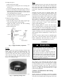
Bearings
This fan system uses bearings featuring concentric split
locking collars. The collars are tightened through a cap
screw bridging the split portion of the collar. The cap
screw has a Torx T25 socket head. To tighten the locking
collar: Hold the locking collar tightly against the inner
race of the bearing and torque the cap screw to 65-- 70
in-- lb (7.4-- 7.9 Nm). See Fig. 7.
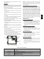
Condenser Coil
The condenser coil is fabricated with round tube copper
hairpins and plate fins of various materials and/or coatings
(see Model Number Format in the Appendix to identify
the materials provided in this unit). The coil may be
one-- row or composite-- type two-- row. Composite two-- row
coils are two single-- row coils fabricated with a single
return bend end tubesheet.
Condenser Coil Maintenance and Cleaning
Recommendation
Fig. 7 - Tightening Locking Collar
C08121
Routine cleaning of coil surfaces is essential to maintain
proper operation of the unit. Elimination of contamination
and removal of harmful residues will greatly increase the
5
48TC
To change fan speed:
life of the coil and extend the life of the unit. The
following maintenance and cleaning procedures are
recommended as part of the routine maintenance activities
to extend the life of the coil.
Two-- Row Coils
Clean coil as follows:
1. Turn off unit power, tag disconnect.
2. Remove top panel screws on condenser end of unit.
3. Remove condenser coil corner post. See Fig. 8. To
hold top panel open, place coil corner post between
top panel and center post. See Fig. 9.
Remove Surface Loaded Fibers
48TC
Surface loaded fibers or dirt should be removed with a
vacuum cleaner. If a vacuum cleaner is not available, a
soft non-- metallic bristle brush may be used. In either
case, the tool should be applied in the direction of the fins.
Coil surfaces can be easily damaged (fin edges can be
easily bent over and damage to the coating of a protected
coil) if the tool is applied across the fins.
NOTE: Use of a water stream, such as a garden hose,
against a surface loaded coil will drive the fibers and dirt
into the coil. This will make cleaning efforts more
difficult. Surface loaded fibers must be completely
removed prior to using low velocity clean water rinse.
Periodic Clean Water Rinse
A periodic clean water rinse is very beneficial for coils
that are applied in coastal or industrial environments.
However, it is very important that the water rinse is made
with a very low velocity water stream to avoid damaging
the fin edges. Monthly cleaning as described below is
recommended.
Fig. 8 - Cleaning Condenser Coil
C08205
Routine Cleaning of Coil Surfaces
Periodic cleaning with TotalineR environmentally sound
coil cleaner is essential to extend the life of coils. This
cleaner is available from Carrier Replacement
Components Division as part number P902-- 0301 for a one
gallon container, and part number P902-- 0305 for a 5
gallon container. It is recommended that all coils,
including standard aluminum, pre-- coated, copper/copper
or E-- coated coils be cleaned with the Totaline
environmentally sound coil cleaner as described below.
Coil cleaning should be part of the unit’s regularly
scheduled maintenance procedures to ensure long life of
the coil. Failure to clean the coils may result in reduced
durability in the environment.
Fig. 9 - Propping Up Top Panel
4. Remove screws securing coil to compressor plate and
compressor access panel.
5. Remove fastener holding coil sections together at return end of condenser coil. Carefully separate the outer coil section 3 to 4 in. from the inner coil section.
See Fig. 10.
Avoid use of:
S
S
S
S
C08206
coil brighteners
acid cleaning prior to painting
high pressure washers
poor quality water for cleaning
Totaline environmentally sound coil cleaner is
nonflammable, hypo allergenic, non bacterial, and a
USDA accepted biodegradable agent that will not harm
the coil or surrounding components such as electrical
wiring, painted metal surfaces, or insulation. Use of
non-- recommended coil cleaners is strongly discouraged
since coil and unit durability could be affected.
One-- Row Coil
Wash coil with commercial coil cleaner. It is not
necessary to remove top panel.
Fig. 10 - Separating Coil Sections
6
C08207
7.
8.
9.
10.
11.
S 2-- 1/2 gallon garden sprayer
S Water rinse with low velocity spray nozzle
!
CAUTION
UNIT DAMAGE HAZARD
Failure to follow this caution may result in accelerated
corrosion of unit parts.
Harsh chemicals, household bleach or acid or basic
cleaners should not be used to clean outdoor or indoor
coils of any kind. These cleaners can be very difficult
to rinse out of the coil and can accelerate corrosion at
the fin/tube interface where dissimilar materials are in
contact. If there is dirt below the surface of the coil,
use the Totaline environmentally sound coil cleaner.
!
CAUTION
UNIT DAMAGE HAZARD
Failure to follow this caution may result in reduced
unit performance or unit shutdown.
High velocity water from a pressure washer, garden
hose, or compressed air should never be used to
clean a coil. The force of the water or air jet will
bend the fin edges and increase airside pressure drop.
Totaline Environmentally Sound Coil Cleaner
Application Instructions
1. Proper eye protection such as safety glasses is recommended during mixing and application.
2. Remove all surface loaded fibers and dirt with a vacuum cleaner as described above.
3. Thoroughly wet finned surfaces with clean water and
a low velocity garden hose, being careful not to bend
fins.
4. Mix Totaline environmentally sound coil cleaner in a
2-- 1/2 gallon garden sprayer according to the instructions included with the cleaner. The optimum solution
temperature is 100_F.
NOTE: Do NOT USE water in excess of 130_F, as the
enzymatic activity will be destroyed.
5. Thoroughly apply Totaline environmentally sound
coil cleaner solution to all coil surfaces including
finned area, tube sheets and coil headers.
6. Hold garden sprayer nozzle close to finned areas and
apply cleaner with a vertical, up-- and-- down motion.
Avoid spraying in horizontal pattern to minimize potential for fin damage.
Ensure cleaner thoroughly penetrates deep into finned
areas.
Interior and exterior finned areas must be thoroughly
cleaned.
Finned surfaces should remain wet with cleaning
solution for 10 minutes.
Ensure surfaces are not allowed to dry before rinsing.
Reapplying cleaner as needed to ensure 10-- minute
saturation is achieved.
Thoroughly rinse all surfaces with low velocity clean
water using downward rinsing motion of water spray
nozzle. Protect fins from damage from the spray
nozzle.
Evaporator Coil
Cleaning the Evaporator Coil
1. Turn unit power off. Install lockout tag. Remove
evaporator coil access panel.
2. If economizer or two-- position damper is installed, remove economizer by disconnecting Molex plug and
removing mounting screws.
3. Slide filters out of unit.
4. Clean coil using a commercial coil cleaner or dishwasher detergent in a pressurized spray canister. Wash
both sides of coil and flush with clean water. For best
results, back-- flush toward return-- air section to remove foreign material. Flush condensate pan after
completion.
5. Reinstall economizer and filters.
6. Reconnect wiring.
7. Replace access panels.
Evaporator Coil Metering Devices
The metering devices are multiple fixed-- bore devices
(Acutrolt) swedged into the horizontal outlet tubes from
the liquid header, located at the entrance to each
evaporator coil circuit path. These are non-- adjustable.
Service requires replacing the entire liquid header
assembly.
To check for possible blockage of one or more of these
metering devices, disconnect the supply fan contactor
(IFC) coil, then start the compressor and observe the
frosting pattern on the face of the evaporator coil. A frost
pattern should develop uniformly across the face of the
coil starting at each horizontal header tube. Failure to
develop frost at an outlet tube can indicate a plugged or a
missing orifice.
Refrigerant System Pressure Access Ports
There are two access ports in the system - on the suction
tube near the compressor and on the discharge tube near
the compressor. These are brass fittings with black plastic
caps. The hose connection fittings are standard 1/4 SAE
male flare couplings.
The brass fittings are two-- piece High Flow valves, with a
receptacle base brazed to the tubing and an integral
spring-- closed check valve core screwed into the base.
7
48TC
6. Use a water hose or other suitable equipment to flush
down between the 2 coil sections to remove dirt and
debris. Clean the outer surfaces with a stiff brush in
the normal manner.
7. Secure inner and outer coil rows together with a
field-- supplied fastener.
8. Reposition the outer coil section and remove the coil
corner post from between the top panel and center
post. Reinstall the coil corner post and replace all
screws.
Totaline Environmentally Sound Coil Cleaner
Application Equipment
(See Fig. 11.) This check valve is permanently assembled
into this core body and cannot be serviced separately;
replace the entire core body if necessary. Service tools are
available from RCD that allow the replacement of the
check valve core without having to recover the entire
system refrigerant charge. Apply compressor refrigerant
oil to the check valve core’s bottom o-- ring. Install the
fitting body with 96 +/ - 10 in-- lbs of torque; do not
overtighten.
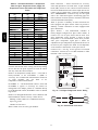
PURONR (R--410A) REFRIGERANT
48TC
This unit is designed for use with Puron (R-- 410A)
refrigerant. Do not use any other refrigerant in this
system.
Puron (R-- 410A) refrigerant is provided in pink (rose)
colored cylinders. These cylinders are available with and
without dip tubes; cylinders with dip tubes will have a
label indicating this feature. For a cylinder with a dip
tube, place the cylinder in the upright position (access
valve at the top) when removing liquid refrigerant for
charging. For a cylinder without a dip tube, invert the
cylinder (access valve on the bottom) when removing
liquid refrigerant.
Because Puron (R-- 410A) refrigerant is a blend, it is
strongly recommended that refrigerant always be removed
from the cylinder as a liquid. Admit liquid refrigerant into
the system in the discharge line. If adding refrigerant into
the suction line, use a commercial metering/expansion
device at the gauge manifold; remove liquid from the
cylinder, pass it through the metering device at the gauge
set and then pass it into the suction line as a vapor. Do not
remove Puron (R-- 410A) refrigerant from the cylinder as a
vapor.
Refrigerant Charge
Amount of refrigerant charge is listed on the unit’s
nameplate. Refer to Carrier GTAC2-- 5 Charging,
Recovery, Recycling and Reclamation training manual
and the following procedures.
Unit panels must be in place when unit is operating during
the charging procedure.
No Charge
Use standard evacuating techniques. After evacuating
system, weigh in the specified amount of refrigerant.
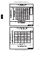
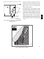
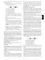
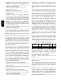
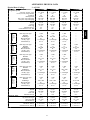
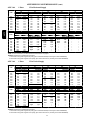
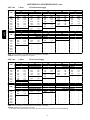
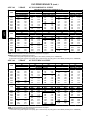
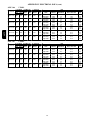
Low-- Charge Cooling
Using Cooling Charging Charts, Fig. 12, vary refrigerant
until the conditions of the appropriate chart are met. Note
the charging charts are different from type normally used.
Charts are based on charging the units to the correct
superheat for the various operating conditions. Accurate
pressure gauge and temperature sensing device are
required. Connect the pressure gauge to the service port
on the suction line. Mount the temperature sensing device
on the suction line and insulate it so that outdoor ambient
temperature does not affect the reading. Indoor-- air cfm
must be within the normal operating range of the unit.
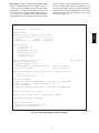
To Use Cooling Charging Charts
Take the outdoor ambient temperature and read the
suction pressure gauge. Refer to chart to determine what
suction temperature should be. If suction temperature is
high, add refrigerant. If suction temperature is low,
carefully recover some of the charge. Recheck the suction
pressure as charge is adjusted.
SEAT
CORE
(Part No. EC39EZ067)
1/2-20 UNF RH
0.596
45
o
o
30
WASHER
O-RING
5/8” HEX
.47
1/2" HEX
This surface provides a metal to metal seal when
torqued into the seat. Appropriate handling is
required to not scratch or dent the surface.
Fig. 11 - CoreMax Access Port Assembly
8
DEPRESSOR PER ARI 720
+.01/-.035
FROM FACE OF BODY
7/16-20 UNF RH
C08453
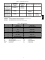
A04
A05
A06
A07
A08
A09
A12
NOMINAL TONS
REFERENCE
3
4
5
6
7.5
8.5
10
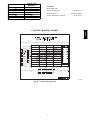
EXAMPLE:
Model 48TC*A04
Outdoor Temperature . . . . . . . . . . . . . . . . . . 85_F (29_C)
Suction Pressure . . . . . . . . . . . . . . . . . 140 psig (965 kPa)
Suction Temperature should be . . . . . . . . . . 60_F (16_C)
COOLING CHARGING CHARTS
48TC
SIZE DESIGNATION
Fig. 12 - Cooling Charging Charts
9
C08203
48TC
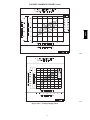
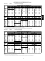
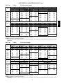
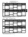
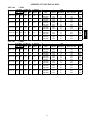
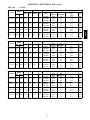
COOLING CHARGING CHARTS (cont.)
C08204
Fig. 12 (cont.) - Cooling Charging Charts
10
C08228
48TC
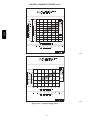
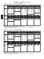
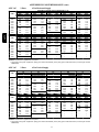
COOLING CHARGING CHARTS (cont.)
C08229
Fig. 12 (cont.) - Cooling Charging Charts
11
C08437
48TC
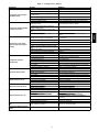
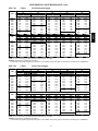
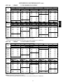
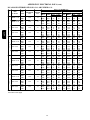
COOLING CHARGING CHARTS (cont.)
C08438
Fig. 12 (cont.) - Cooling Charging Charts
12
C08439
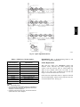
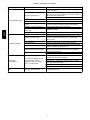
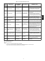
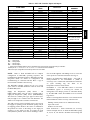
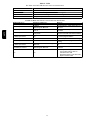
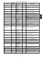
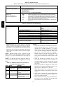
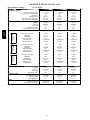
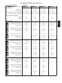
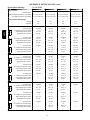
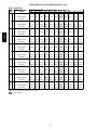
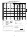
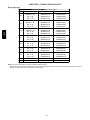
Table 1 – Cooling Service Analysis
Compressor and Condenser
Fan Will Not Start.
Compressor Will Not Start But
Condenser Fan Runs.
CAUSE
Power failure.
Fuse blown or circuit breaker tripped.
Defective thermostat, contactor, transformer,
or control relay.
Insufficient line voltage.
Incorrect or faulty wiring.
Thermostat setting too high.
Faulty wiring or loose connections in
compressor circuit.
Compressor motor burned out, seized, or
internal overload open.
Defective run/start capacitor, overload, start
relay.
One leg of three--- phase power dead.
Refrigerant overcharge or undercharge.
Compressor Cycles (other
than normally satisfying thermostat).
Compressor Operates
Continuously.
Excessive Head Pressure.
Head Pressure Too Low.
Excessive Suction Pressure.
Suction Pressure Too Low.
Evaporator Fan Will Not Shut
Off.
Compressor Makes Excessive
Noise.
Defective compressor.
Insufficient line voltage.
Blocked condenser.
Defective run/start capacitor, overload, or start
relay.
Defective thermostat.
Faulty condenser--- fan motor or capacitor.
Restriction in refrigerant system.
Dirty air filter.
Unit undersized for load.
Thermostat set too low.
Low refrigerant charge.
Leaking valves in compressor.
Air in system.
Condenser coil dirty or restricted.
Dirty air filter.
Dirty condenser coil.
Refrigerant overcharged.
Air in system.
Condenser air restricted or air short--- cycling.
Low refrigerant charge.
Compressor valves leaking.
Restriction in liquid tube.
High head load.
Compressor valves leaking.
Refrigerant overcharged.
Dirty air filter.
Low refrigerant charge.
Metering device or low side restricted.
REMEDY
Call power company.
Replace fuse or reset circuit breaker.
Replace component.
Determine cause and correct.
Check wiring diagram and rewire correctly.
Lower thermostat setting below room temperature.
Check wiring and repair or replace.
Determine cause. Replace compressor.
Determine cause and replace.
Replace fuse or reset circuit breaker. Determine
cause.
Recover refrigerant, evacuate system, and recharge
to nameplate.
Replace and determine cause.
Determine cause and correct.
Determine cause and correct.
Determine cause and replace.
Temperature too low in conditioned area.
Outdoor ambient below 25˚F.
Replace thermostat.
Replace.
Locate restriction and remove.
Replace filter.
Decrease load or increase unit size.
Reset thermostat.
Locate leak; repair and recharge.
Replace compressor.
Recover refrigerant, evacuate system, and recharge.
Clean coil or remove restriction.
Replace filter.
Clean coil.
Recover excess refrigerant.
Recover refrigerant, evacuate system, and recharge.
Determine cause and correct.
Check for leaks; repair and recharge.
Replace compressor.
Remove restriction.
Check for source and eliminate.
Replace compressor.
Recover excess refrigerant.
Replace filter.
Check for leaks; repair and recharge.
Remove source of restriction.
Increase air quantity. Check filter and replace if
necessary.
Reset thermostat.
Install low--- ambient kit.
Time off delay not finished.
Wait for 30--- second off delay.
Compressor rotating in wrong direction.
Reverse the 3--- phase power leads.
Insufficient evaporator airflow.
13
48TC
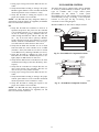
PROBLEM
Compressor
2. Remove condenser-- fan assembly (grille, motor, and
fan).
3. Loosen fan hub setscrews.
4. Adjust fan height as shown in Fig. 13.
5. Tighten setscrews.
6. Replace condenser-- fan assembly.
Lubrication
The compressor is charged with the correct amount of oil
at the factory.
48TC
!
CAUTION
UNIT DAMAGE HAZARD
Failure to follow this caution may result in damage to
components.
The compressor is in a PuronR refrigerant system and
uses a polyolester (POE) oil. This oil is extremely
hygroscopic, meaning it absorbs water readily. POE
oils can absorb 15 times as much water as other oils
designed for HCFC and CFC refrigerants. Avoid
exposure of the oil to the atmosphere.
Replacing Compressor
Conduit
0.14 in + 0.0 / -0.03
Fig. 13 - Condenser Fan Adjustment
Troubleshooting Cooling System
Refer to Table 1 for additional troubleshooting topics.
The compressor used with Puron refrigerant contains a
POE oil. This oil has a high affinity for moisture. Do not
remove the compressor’s tube plugs until ready to insert
the unit suction and discharge tube ends.
CONVENIENCE OUTLETS
!
Compressor mounting bolt torque is 65-- 75 ft-- lbs.
WARNING
ELECTRICAL OPERATION HAZARD
Failure to follow this warning could result in personal
injury or death.
Units with convenience outlet circuits may use
multiple disconnects. Check convenience outlet for
power status before opening unit for service. Locate
its disconnect switch, if appropriate, and open it.
Tag-- out this switch, if necessary.
Compressor Rotation
On 3-- phase units with scroll compressors, it is important
to be certain compressor is rotating in the proper
direction. To determine whether or not compressor is
rotating in the proper direction:
1. Connect service gauges to suction and discharge pressure fittings.
2. Energize the compressor.
3. The suction pressure should drop and the discharge
pressure should rise, as is normal on any start-- up.
NOTE: If the suction pressure does not drop and the
discharge pressure does not rise to normal levels:
4. Note that the evaporator fan is probably also rotating
in the wrong direction.
5. Turn off power to the unit.
6. Reverse any two of the unit power leads.
7. Reapply power to the compressor.
C08448
Two types of convenience outlets are offered on 48TC
models: Non-- powered and unit-- powered. Both types
provide
a
125-- volt
GFCI
(ground-- fault
circuit-- interrupter) duplex receptacle rated at 15-- A
behind a hinged waterproof access cover, located on the
end panel of the unit. See Fig. 14.
Pwd-CO Transformer
Conv Outlet
GFCI
Pwd-CO
Fuse
Switch
The suction and discharge pressure levels should now
move to their normal start-- up levels.
NOTE: When the compressor is rotating in the wrong
direction, the unit makes an elevated level of noise and
does not provide cooling.
Filter Drier
Replace whenever refrigerant system is exposed to
atmosphere. Only use factory specified liquid-- line filter
driers with working pressures no less than 650 psig. Do
not install a suction-- line filter drier in liquid line. A
liquid-- line filter drier designed for use with Puron
refrigerant is required on every unit.
Condenser--Fan Adjustment
1. Shut off unit power supply. Install lockout tag.
Fig. 14 - Convenience Outlet Location
C08128
Non-- powered type: This type requires the field
installation of a general-- purpose 125-- volt 15-- A circuit
powered from a source elsewhere in the building. Observe
national and local codes when selecting wire size, fuse or
14
Unit-- powered type: A unit-- mounted transformer is
factory-- installed to stepdown the main power supply
voltage to the unit to 115-- v at the duplex receptacle. This
option also includes a manual switch with fuse, located in
a utility box and mounted on a bracket behind the
convenience outlet; access is through the unit’s control
box access panel. See Fig. 14.
The primary leads to the convenience outlet transformer
are not factory-- connected. Selection of primary power
source is a customer-- option. If local codes permit, the
transformer primary leads can be connected at the
line-- side terminals on a unit-- mounted non-- fused
disconnect or HACR breaker switch; this will provide
service power to the unit when the unit disconnect switch
or HACR switch is open. Other connection methods will
result in the convenience outlet circuit being de-- energized
when the unit disconnect or HACR switch is open. See
Fig. 15.
lamps, etc; it is not intended to provide 15-- amps loading
for continuous duty loads (such as electric heaters for
overnight use). Observe a 50% limit on circuit loading
above 8-- amps (i.e., limit loads exceeding 8-- amps to 30
minutes of operation every hour).
Maintenance: Periodically test the GFCI receptacle by
pressing the TEST button on the face of the receptacle.
This should cause the internal circuit of the receptacle to
trip and open the receptacle. Check for proper grounding
wires and power line phasing if the GFCI receptacle does
not trip as required. Press the RESET button to clear the
tripped condition.
Fuse on powered type: The factory fuse is a Bussman
“Fusetron” T-- 15, non-- renewable screw-- in (Edison base)
type plug fuse.
Using unit-- mounted convenience outlets: Units with
unit-- mounted convenience outlet circuits will often
require that two disconnects be opened to de-- energize all
power to the unit. Treat all units as electrically energized
until the convenience outlet power is also checked and
de-- energization is confirmed. Observe National Electrical
Code Article 210, Branch Circuits, for use of convenience
outlets.
SMOKE DETECTORS
Smoke detectors are available as factory-- installed options
on 48TC models. Smoke detectors may be specified for
Supply Air only or for Return Air without or with
economizer or in combination of Supply Air and Return
Air. Return Air smoke detectors are arranged for vertical
return configurations only. All components necessary for
operation are factory-- provided and mounted. The unit is
factory-- configured for immediate smoke detector
shutdown operation; additional wiring or modifications to
unit terminal board may be necessary to complete the unit
and smoke detector configuration to meet project
requirements.
CO8283
Fig. 15 - Powered Convenience Outlet Wiring
UNIT
VOLTAGE
208,
230
CONNECT
AS
460
480
575
240
600
PRIMARY
CONNECTIONS
L1: RED +YEL
L2: BLU + GRA
L1: RED
Splice BLU + YEL
L2: GRA
L1: RED
L2: GRA
TRANSFORMER
TERMINALS
H1 + H3
H2 + H4
H1
H2 + H3
H4
H1
H2
Duty Cycle: The unit-- powered convenience outlet has a
duty cycle limitation. The transformer is intended to
provide power on an intermittent basis for service tools,
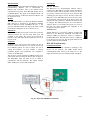
System
The smoke detector system consists of a four-- wire
controller and one or two sensors. Its primary function is
to shut down the rooftop unit in order to prevent smoke
from circulating throughout the building. It is not to be
used as a life saving device.
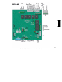
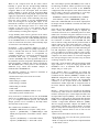
Controller
The controller (see Fig. 16) includes a controller housing,
a printed circuit board, and a clear plastic cover. The
controller can be connected to one or two compatible duct
smoke sensors. The clear plastic cover is secured to the
housing with a single captive screw for easy access to the
wiring terminals. The controller has three LEDs (for
Power, Trouble and Alarm) and a manual test/reset button
(on the cover face).
15
48TC
breaker requirements and disconnect switch size and
location. Route 125-- v power supply conductors into the
bottom of the utility box containing the duplex receptacle.
Duct smoke sensor
Duct smoke sensor
controller
Exhaust tube
Conduit nuts
(supplied by installer)
Exhaust gasket
Sensor housing
and electronics
See
Detail A
Conduit support plate
Terminal block cover
Controller housing
and electronics
Intake
gasket
Cover gasket
(ordering option)
Cover gasket
(ordering option)
Controller cover
Conduit couplings
(supplied by installer)
TSD-CO2
(ordering option)
48TC
Sensor cover
Plug
Fastener
(2X)
Sampling tube
(ordered separately)
Coupling
Detail A
Trouble
Alarm
Power
Test/reset
switch
Magnetic
test/reset
switch
Fig. 16 - Controller Assembly
C08208
Alarm
Trouble
Sensor
The sensor (see Fig. 17) includes a plastic housing, a
printed circuit board, a clear plastic cover, a sampling
tube inlet and an exhaust tube. The sampling tube (when
used) and exhaust tube are attached during installation.
The sampling tube varies in length depending on the size
of the rooftop unit. The clear plastic cover permits visual
inspections without having to disassemble the sensor. The
cover attaches to the sensor housing using four captive
screws and forms an airtight chamber around the sensing
electronics. Each sensor includes a harness with an RJ45
terminal for connecting to the controller. Each sensor has
four LEDs (for Power, Trouble, Alarm and Dirty) and a
manual test/reset button (on the left-- side of the housing).
Air is introduced to the duct smoke detector sensor’s
sensing chamber through a sampling tube that extends into
the HVAC duct and is directed back into the ventilation
system through a (shorter) exhaust tube. The difference in
air pressure between the two tubes pulls the sampled air
through the sensing chamber. When a sufficient amount of
smoke is detected in the sensing chamber, the sensor
signals an alarm state and the controller automatically
takes the appropriate action to shut down fans and
blowers, change over air handling systems, notify the fire
alarm control panel, etc.
Power
Dirty
Fig. 17 - Smoke Detector Sensor
C08209
For installations using two sensors, the duct smoke
detector does not differentiate which sensor signals an
alarm or trouble condition.
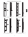
Smoke Detector Locations
Supply Air — The Supply Air smoke detector sensor is
located to the left of the unit’s indoor (supply) fan. See
Fig. 18. Access is through the fan access panel. There is
no sampling tube used at this location. The sampling tube
inlet extends through the side plate of the fan housing
(into a high pressure area). The controller is located on a
bracket to the right of the return filter, accessed through
the lift-- off filter panel.
Smoke Detector Sensor
The sensor uses a process called differential sensing to
prevent gradual environmental changes from triggering
false alarms. A rapid change in environmental conditions,
such as smoke from a fire, causes the sensor to signal an
alarm state but dust and debris accumulated over time
does not.
C08245
Fig. 18 - Typical Supply Air Smoke Detector Sensor
Location
16
Return Air without Economizer — The sampling tube is
located across the return air opening on the unit basepan.
See Fig. 19. The holes in the sampling tube face
downward, into the return air stream. The sampling tube is
connected via tubing to the return air sensor that is
mounted on a bracket high on the partition between return
filter and controller location. (This sensor is shipped in a
flat-- mounting location. Installation requires that this
sensor be relocated to its operating location and the tubing
to the sampling tube be connected. See installation steps
below.)
Completing Installation of Return Air Smoke
Sensor:
Screws
Flexible
Exhaust Tubes
Return Air Detector module
(shipping position shown)*
Sample Tube
Controller module
1. Unscrew the two screws holding the Return Air
Sensor detector plate. See Fig. 21. Save the screws.
2. Remove the Return Air Sensor and its detector plate.
3. Rotate the detector plate so the sensor is facing outwards and the sampling tube connection is on the bottom. See Fig. 22.
4. Screw the sensor and detector plate into its operating
position using screws from Step 1. Make sure the
sampling tube connection is on the bottom and the exhaust tube is on the top. See Fig. 22.
5. Connect the flexible tube on the sampling inlet to the
sampling tube on the basepan.
6. For units with an economizer, the sampling tube is integrated into the economizer housing but the connection of the flexible tubing to the sampling tube is the
same.
Return Air Detector Sampling Tube
*RA detector must be moved from shipping position to operating position by installer
C07307
Fig. 19 - Typical Return Air Detector Location
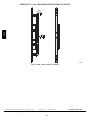
Return Air with Economizer — The sampling tube is
inserted through the side plates of the economizer
housing, placing it across the return air opening on the
unit basepan. See Fig. 20. The holes in the sampling tube
face downward, into the return air stream. The sampling
tube is connected via tubing to the return air sensor that is
mounted on a bracket high on the partition between return
filter and controller location. (This sensor is shipped in a
flat-- mounting location. Installation requires that this
sensor be relocated to its operating location and the tubing
to the sampling tube be connected. See installation steps
below.)
C08127
Fig. 22 - Return Air Sensor Operating Position
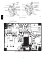
FIOP Smoke Detector Wiring and Response
All units: FIOP smoke detector is configured to
automatically shut down all unit operations when smoke
condition is detected. See Fig. 23, Smoke Detector
Wiring.
Return Air
Sampling Tube
C08129
Fig. 20 - Return Air Sampling Tube Location
Highlight A: JMP 3 is factory-- cut, transferring unit
control to smoke detector.
Highlight B: Smoke detector NC contact set will open on
smoke alarm condition, de-- energizing the ORN
conductor.
17
48TC
C08126
Fig. 21 - Return Air Detector Shipping Position
B
D
C
F
48TC
E
A
Fig. 23 - Typical Smoke Detector System Wiring
Highlight C: 24-- v power signal via ORN lead is removed
at Smoke Detector input on LCTB; all unit operations
cease immediately.
PremierLink and RTU-- MP Controls: Unit operating
functions (fan, cooling and heating) are terminated as
described above. In addition:
Sensor and Controller Tests
Sensor Alarm Test
The sensor alarm test checks a sensor’s ability to signal an
alarm state. This test requires that you use a field provided
SD-- MAG test magnet.
!
Highlight D: On smoke alarm condition, the smoke
detector NO Alarm contact will close, supplying 24-- v
power to GRA conductor.
Premier-- Link: This signal is conveyed to PremierLink
FIOP’s TB1 at terminal TB1-- 6 (BLU lead). This signal
initiates the FSD sequence by the PremierLink control.
FSD status is reported to connected CCN network.
Using Remote Logic: Five conductors are provided for
field use (see Highlight F) for additional annunciation
functions.
Additional Application Data — Refer to Catalog No.
HKRNKA-- 1XA for discussions on additional control
features of these smoke detectors including multiple unit
coordination. See Fig. 23.
CAUTION
OPERATIONAL TEST HAZARD
Failure to follow this caution may result in personnel
and authority concern.
This test places the duct detector into the alarm state.
Unless part of the test, disconnect all auxiliary
equipment from the controller before performing the
test. If the duct detector is connected to a fire alarm
system, notify the proper authorities before
performing the test.
Highlight E: GRA lead at Smoke Alarm input on LCTB
provides 24-- v signal to FIOP DDC control.
RTU-- MP: The 24-- v signal is conveyed to RTU-- MP’s
J1-- 10 input terminal. This signal initiates the FSD
sequence by the RTU-- MP control. FSD status is reported
to connected BAS network.
C08246
Sensor Alarm Test Procedure
1. Hold the test magnet where indicated on the side of
the sensor housing for seven seconds.
2. Verify that the sensor’s Alarm LED turns on.
3. Reset the sensor by holding the test magnet against
the sensor housing for two seconds.
4. Verify that the sensor’s Alarm LED turns off.
Controller Alarm Test
The controller alarm test checks the controller’s ability to
initiate and indicate an alarm state.
18
Table 2 – Dirty LED Test
CAUTION
OPERATIONAL TEST HAZARD
Failure to follow this caution may result in personnel
and authority concern.
This test places the duct detector into the alarm state.
Disconnect all auxiliary equipment from the controller
before performing the test. If the duct detector is
connected to a fire alarm system, notify the proper
authorities before performing the test.
Controller Alarm Test Procedure
1. Press the controller’s test/reset switch for seven
seconds.
2. Verify that the controller’s Alarm LED turns on.
3. Reset the sensor by pressing the test/reset switch for
two seconds.
4. Verify that the controller’s Alarm LED turns off.
Dirty Controller Test
CAUTION
OPERATIONAL TEST HAZARD
Failure to follow this caution may result in personnel
and authority concern.
Pressing the controller’s test/reset switch for longer
than seven seconds will put the duct detector into the
alarm state and activate all automatic alarm responses.
Dirty Controller Test Procedure
1. Press the controller’s test/reset switch for two
seconds.
2. Verify that the controller’s Trouble LED flashes.
Dirty Sensor Test
The dirty sensor test provides an indication of the sensor’s
ability to compensate for gradual environmental changes.
A sensor that can no longer compensate for environmental
changes is considered 100% dirty and requires cleaning or
replacing. You must use a field provided SD-- MAG test
magnet to initiate a sensor dirty test. The sensor’s Dirty
LED indicates the results of the dirty test as shown in
Table 2.
!
CAUTION
DESCRIPTION
1
0--- 25% dirty. (Typical of a newly installed detector)
2
25--- 50% dirty
3
51--- 75% dirty
4
76--- 99% dirty
Dirty Sensor Test Procedure
1. Hold the test magnet where indicated on the side of
the sensor housing for two seconds.
2. Verify that the sensor’s Dirty LED flashes.
!
CAUTION
OPERATIONAL TEST HAZARD
Failure to follow this caution may result in personnel
and authority concern.
Changing the dirty sensor test operation will put the
detector into the alarm state and activate all automatic
alarm responses. Before changing dirty sensor test
operation, disconnect all auxiliary equipment from the
controller and notify the proper authorities if
connected to a fire alarm system.
The dirty controller test checks the controller’s ability to
initiate a dirty sensor test and indicate its results.
!
FLASHES
Changing the Dirt Sensor Test
By default, sensor dirty test results are indicated by:
S The sensor’s Dirty LED flashing.
S The controller’s Trouble LED flashing.
S The controller’s supervision relay contacts toggle.
The operation of a sensor’s dirty test can be changed so
that the controller’s supervision relay is not used to
indicate test results. When two detectors are connected to
a controller, sensor dirty test operation on both sensors
must be configured to operate in the same manner.
To Configure the Dirty Sensor Test Operation
1. Hold the test magnet where indicated on the side of
the sensor housing until the sensor’s Alarm LED turns
on and its Dirty LED flashes twice (approximately 60
seconds).
2. Reset the sensor by removing the test magnet then
holding it against the sensor housing again until the
sensor’s Alarm LED turns off (approximately 2
seconds).
Remote Station Test
The remote station alarm test checks a test/reset station’s
ability to initiate and indicate an alarm state.
!
OPERATIONAL TEST HAZARD
Failure to follow this caution may result in personnel
and authority concern.
Holding the test magnet against the sensor housing for
more than seven seconds will put the duct detector
into the alarm state and activate all automatic alarm
responses.
CAUTION
OPERATIONAL TEST HAZARD
Failure to follow this caution may result in personnel
and authority concern.
This test places the duct detector into the alarm state.
Unless part of the test, disconnect all auxiliary
equipment from the controller before performing the
test. If the duct detector is connected to a fire alarm
system, notify the proper authorities before
performing the test.
19
48TC
!
48TC
SD-- TRK4 Remote Alarm Test Procedure
1. Turn the key switch to the RESET/TEST position for
seven seconds.
2. Verify that the test/reset station’s Alarm LED turns
on.
3. Reset the sensor by turning the key switch to the
RESET/TEST position for two seconds.
4. Verify that the test/reset station’s Alarm LED turns
off.
Remote Test/Reset Station Dirty Sensor Test
The test/reset station dirty sensor test checks the test/reset
station’s ability to initiate a sensor dirty test and indicate
the results. It must be wired to the controller as shown in
Fig. 24 and configured to operate the controller’s
supervision relay. For more information, see “Changing
sensor dirty test operation.”
Dirty Sensor Test Using an SD-- TRK4
1. Turn the key switch to the RESET/TEST position for
two seconds.
2. Verify that the test/reset station’s Trouble LED
flashes.
Detector Cleaning
Cleaning the Smoke Detector
Clean the duct smoke sensor when the Dirty LED is
flashing continuously or sooner if conditions warrant.
!
OPERATIONAL TEST HAZARD
Failure to follow this caution may result in personnel
and authority concern.
If the smoke detector is connected to a fire alarm
system, first notify the proper authorities that the
detector is undergoing maintenance then disable the
relevant circuit to avoid generating a false alarm.
12
Smoke Detector Controller
1
TB3
3
1
−
2
+
CAUTION
1. Disconnect power from the duct detector then remove
the sensor’s cover. (See Fig. 25.)
Auxiliary
equipment
14
Sampling
tube
SD-TRK4
Supervision relay
contacts [3]
Trouble
13
19
Wire must be
added by installer
5
18 Vdc ( +)
HVAC duct
Sensor
housing
Power
4
Alarm
Optic
plate
Airflow
15
1
2
3
Retainer
clip
2
Optic
housing
Reset/Test
20
18 Vdc ( −)
C08247
Fig. 24 - Remote Test/Reset Station Connections
!
Fig. 25 - Sensor Cleaning Diagram
CAUTION
2. Using a vacuum cleaner, clean compressed air, or a
soft bristle brush, remove loose dirt and debris from
inside the sensor housing and cover.
Use isopropyl alcohol and a lint-- free cloth to remove
dirt and other contaminants from the gasket on the
sensor’s cover.
3. Squeeze the retainer clips on both sides of the optic
housing then lift the housing away from the printed
circuit board.
4. Gently remove dirt and debris from around the optic
plate and inside the optic housing.
5. Replace the optic housing and sensor cover.
6. Connect power to the duct detector then perform a
sensor alarm test.
OPERATIONAL TEST HAZARD
Failure to follow this caution may result in personnel
and authority concern.
If the test/reset station’s key switch is left in the
RESET/TEST position for longer than seven seconds,
the detector will automatically go into the alarm state
and activate all automatic alarm responses.
!
CAUTION
OPERATIONAL TEST HAZARD
Failure to follow this caution may result in personnel
and authority concern.
Holding the test magnet to the target area for longer
than seven seconds will put the detector into the alarm
state and activate all automatic alarm responses.
C07305
INDICATORS
Normal State
The smoke detector operates in the normal state in the
absence of any trouble conditions and when its sensing
chamber is free of smoke. In the normal state, the Power
20
Trouble
Alarm
Power
Test/reset
switch
Fig. 26 - Controller Assembly
NOTE: All troubles are latched by the duct smoke
detector. The trouble condition must be cleared and then
the duct smoke detector must be reset in order to restore it
to the normal state.
Resetting Alarm and Trouble Condition Trips:
Manual reset is required to restore smoke detector systems
to Normal operation. For installations using two sensors,
the duct smoke detector does not differentiate which
sensor signals an alarm or trouble condition. Check each
sensor for Alarm or Trouble status (indicated by LED).
Clear the condition that has generated the trip at this
sensor. Then reset the sensor by pressing and holding the
reset button (on the side) for 2 seconds. Verify that the
sensor’s Alarm and Trouble LEDs are now off. At the
controller, clear its Alarm or Trouble state by pressing and
holding the manual reset button (on the front cover) for 2
seconds. Verify that the controller’s Alarm and Trouble
LEDs are now off. Replace all panels.
Troubleshooting
Controller’s Trouble LED is On
1. Check the Trouble LED on each sensor connected to
the controller. If a sensor’s Trouble LED is on, determine the cause and make the necessary repairs.
2. Check the wiring between the sensor and the controller. If wiring is loose or missing, repair or replace as
required.
Controller’s Trouble LED is Flashing
1. One or both of the sensors is 100% dirty.
2. Determine which Dirty LED is flashing then clean
that sensor assembly as described in the detector
cleaning section.
Sensor’s Trouble LED is On
1. Check the sensor’s Dirty LED. If it is flashing, the
sensor is dirty and must be cleaned.
2. Check the sensor’s cover. If it is loose or missing, secure the cover to the sensor housing.
3. Replace sensor assembly.
Sensor’s Power LED is Off
1. Check the controller’s Power LED. If it is off, determine why the controller does not have power and
make the necessary repairs.
2. Check the wiring between the sensor and the controller. If wiring is loose or missing, repair or replace as
required.
C07298
Table 3 – Detector Indicators
CONTROL OR INDICATOR
Magnetic test/reset switch
Alarm LED
Trouble LED
Dirty LED
Power LED
DESCRIPTION
Resets the sensor when it is in the alarm or trouble state. Activates or tests the sensor when it is in
the normal state.
Indicates the sensor is in the alarm state.
Indicates the sensor is in the trouble state.
Indicates the amount of environmental compensation used by the sensor
(flashing continuously = 100%)
Indicates the sensor is energized.
21
48TC
LED on both the sensor and the controller are on and all
other LEDs are off.
Alarm State
The smoke detector enters the alarm state when the
amount of smoke particulate in the sensor’s sensing
chamber exceeds the alarm threshold value. (See Table 3.)
Upon entering the alarm state:
S The sensor’s Alarm LED and the controller’s Alarm LED
turn on.
S The contacts on the controller’s two auxiliary relays
switch positions.
S The contacts on the controller’s alarm initiation relay
close.
S The controller’s remote alarm LED output is activated
(turned on).
S The controller’s high impedance multiple fan shutdown
control line is pulled to ground Trouble state.
The SuperDuct duct smoke detector enters the trouble
state under the following conditions:
S A sensor’s cover is removed and 20 minutes pass before
it is properly secured.
S A sensor’s environmental compensation limit is reached
(100% dirty).
S A wiring fault between a sensor and the controller is
detected.
An internal sensor fault is detected upon entering the
trouble state:
S The contacts on the controller’s supervisory relay switch
positions. (See Fig. 26.)
S If a sensor trouble, the sensor’s Trouble LED the
controller’s Trouble LED turn on.
S If 100% dirty, the sensor’s Dirty LED turns on and the
controller’s Trouble LED flashes continuously.
S If a wiring fault between a sensor and the controller, the
controller’s Trouble LED turns on but not the sensor’s.
48TC
Controller’s Power LED is Off
1. Make sure the circuit supplying power to the controller is operational. If not, make sure JP2 and JP3 are
set correctly on the controller before applying power.
2. Verify that power is applied to the controller’s supply
input terminals. If power is not present, replace or repair wiring as required.
Remote Test/Reset Station’s Trouble LED Does Not
flash When Performing a Dirty Test, But the Controller’s Trouble LED Does
1. Verify that the remote test/station is wired as shown
in Fig. 24. Repair or replace loose or missing wiring.
2. Configure the sensor dirty test to activate the controller’s supervision relay. See “Changing sensor dirty
test operation.”
Sensor’s Trouble LED is On, But the Controller’s
Trouble LED is OFF
Remove JP1 on the controller.
PROTECTIVE DEVICES
Compressor Protection
The standard supply fan motor is equipped with internal
overcurrent and overtemperature protection. Protection
devices reset automatically.
The High Static option supply fan motor is equipped with
a pilot-- circuit Thermix combination overtemperature/
overcurrent protection device. This device resets
automatically. Do not bypass this switch to correct
trouble. Determine the cause and correct it.
Condenser Fan Motor Protection
The condenser fan motor is internally protected against
overtemperature.
Relief Device
A soft solder joint at the suction service access port
provides pressure relief under abnormal temperature and
pressure conditions (i.e., fire in building). Protect this
joint during brazing operations near this joint.
Control Circuit, 24--V
The control circuit is protected against overcurrent
conditions by a circuit breaker mounted on control
transformer TRAN. Reset is manual.
Overcurrent
GAS HEATING SYSTEM
The compressor has internal linebreak motor protection.
Overtemperature
General
The compressor has an internal protector to protect it
against excessively high discharge gas temperatures.
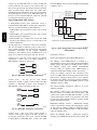
The heat exchanger system consists of a gas valve feeding
multiple inshot burners off a manifold. The burners fire
into matching primary tubes. The primary tubes discharge
into combustion plenum where gas flow converges into
secondary tubes. The secondary tubes exit into the
induced draft fan wheel inlet. The induced fan wheel
discharges into a flue passage and flue gases exit out a
flue hood on the side of the unit. The induced draft fan
motor includes a Hall Effect sensor circuit that confirms
adequate wheel speed via the Integrated Gas Control
(IGC) board. Safety switches include a Rollout Switch (at
the top of the burner compartment) and a limit switch
(mounted through the fan deck, over the tubes). (See Fig.
27 and Fig. 28.)
High Pressure Switch
The system is provided with a high pressure switch
mounted on the discharge line. The switch is
stem-- mounted and brazed into the discharge tube. Trip
setting is 630 psig +/-- 10 psig (4344 +/-- 69 kPa) when
hot. Reset is automatic at 505 psig (3482 kPa).
Low Pressure Switch
The system is protected against a loss of charge and low
evaporator coil loading condition by a low pressure switch
located on the suction line near the compressor. The
switch is stem-- mounted. Trip setting is 54 psig +/-- 5 psig
(372 +/-- 34 kPa). Reset is automatic at 117 +/-- 5 psig
(807 +/-- 34 kPa).
INDUCEDDRAFT
MOTOR
MOUNTING
PLATE
Evaporator Freeze Protection
The system is protected against evaporator coil frosting
and low temperature conditions by a temperature switch
mounted on the evaporator coil hairpin. Trip setting is
30_F +/-- 5_F (-- 1_C +/-- 3_C). Reset is automatic at 45_F
(7_C).
BURNER
SECTION
INDUCEDDRAFT
MOTOR
MANIFOLD
PRESSURE
TAP
Supply (Indoor) Fan Motor Protection
ROLLOUT
SWITCH
FLUE
EXHAUST
VESTIBULE
PLATE
BLOWER
HOUSING
GAS
VALVE
Disconnect and lockout power when servicing fan motor.
Fig. 27 - Burner Section Details
22
C06152
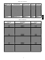
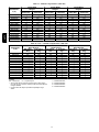
Table 6 – Liquid Propane Supply Line Pressure Ranges
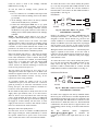
Limit Switch
and Shield
UNIT MODEL
48TCD,E,F
48TCS,R,T
48TCL,M,N
UNIT SIZE
MIN
11.0 in. wg
(2740 Pa)
NA
All
All
MAX
13.0 in. wg
(3240 Pa)
NA
Manifold pressure for LP fuel use must be adjusted to
specified range. Follow instructions in the accessory kit to
make initial readjustment.
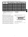
Table 7 – Liquid Propane Manifold Pressure Ranges
Fig. 28 - Limit Switch Location
UNIT MODEL
48TCD,S
48TCE,R
48TCF,T
Gas line pressure entering the unit’s main gas valve must
be within specified ranges. Adjust unit gas regulator valve
as required or consult local gas utility.
Table 4 – Natural Gas Supply Line Pressure Ranges
UNIT MODEL
UNIT SIZE
48TC
All
MIN
4.0 in. wg
(996 Pa)
MAX
13.0 in. wg
(3240 Pa)
HIGH FIRE
LOW FIRE
All
10.0 in. wg
(2490 Pa)
5.0 in. wg
(1245 Pa){
All
NA
NA
48TCL,
48TCM,
48TCN
Fuel Types and Pressures
Natural Gas — The 48TC unit is factory-- equipped for use
with Natural Gas fuel at elevation under 2000 ft (610 m).
See section Orifice Replacement for information in
modifying this unit for installation at elevations above
2000 ft (610 m).
UNIT SIZE
48TC
C08284
NA: Not Available
{ 3 Phase models only
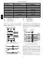
Supply Pressure Switch — The LP conversion kit includes
a supply low pressure switch. The switch contacts (from
terminal C to terminal NO) will open the gas valve power
whenever the supply line pressure drops below the
setpoint. See Fig. 29 and Fig. 30. If the low pressure
remains open for 15 minutes during a call for heat, the
IGC circuit will initiate a Ignition Fault (5 flashes)
lockout. Reset of the low pressure switch is automatic on
rise in supply line pressure. Reset of the IGC requires a
recycle of unit power after the low pressure switch has
closed.
Manifold pressure is factory-- adjusted for NG fuel use.
Adjust as required to obtain best flame characteristic.
Table 5 – Natural Gas Manifold Pressure Ranges
UNIT
MODEL
48TCD,S
48TCE,R
48TCF,T
48TCL
48TCM
48TCN
UNIT
SIZE
HIGH
FIRE
LOW
FIRE
RANGE
All
3.5 in. wg
(872 Pa)
1.7 in. wg
(423 Pa){
2.0--- 5.0 in. wg (Hi)
(498--- 1245 Pa)
All
3.5 in. wg
(872 Pa)
NA
2.0--- 5.0 in. wg (Hi)
(498--- 1245 Pa)
NA: Not Available
{ 3 Phase models only
Liquid Propane — Accessory packages are available for
field-- installation that will convert the 48TC unit (except
low NOx model) to operate with Liquid Propane (LP)
fuels. These kits include new orifice spuds, new springs
for gas valves and a supply line low pressure switch. See
section on Orifice Replacement for details on orifice size
selections.
Low NOx models include specially-- sized orifices and use
of different flue flow limits and tube baffles. Because of
these extra features, conversion of these models to LP is
not recommended.
Fuel line pressure entering unit gas valve must remain
within specified range.
Fig. 29 - LP Low Pressure Switch (Installed)
LP LPS
IGC
BRN
C
NO
BRN
J2-11
MGV
IGC
TSTAT
C
GRA
J2-12
W2
C08238
PNK
C08285
Fig. 30 - LP Supply Line Low Pressure Switch Wiring
23
This switch also prevents operation when the propane tank
level is low which can result in gas with a high
concentration of impurities, additives, and residues that
have settled to the bottom of the tank. Operation under
these conditions can cause harm to the heat exchanger
system. Contact your fuel supplier if this condition is
suspected.
season, inspect blower wheel bi-- monthly to determine
proper cleaning frequency.
To access burner section, slide the sliding burner partition
out of the unit.
To inspect blower wheel, shine a flashlight into draft hood
opening. If cleaning is required, remove motor and wheel
as follows:
Flue Gas Passageways
1. Slide burner access panel out.
2. Remove the 7 screws that attach induced-- draft motor
housing to vestibule plate. (See Fig. 31.)
3. The blower wheel can be cleaned at this point. If additional cleaning is required, continue with Steps 4
and 5.
4. To remove blower from the motor shaft, remove 2
setscrews.
5. To remove motor, remove the 4 screws that hold the
motor to mounting plate. Remove the motor cooling
fan by removing one setscrew. Then remove nuts that
hold motor to mounting plate.
6. To reinstall, reverse the procedure outlined above.
48TC
To inspect the flue collector box and upper areas of the
heat exchanger:
1. Remove the combustion blower wheel and motor assembly according to directions in Combustion-- Air
Blower section. See Fig. 31.
2. Remove the flue cover to inspect the heat exchanger.
3. Clean all surfaces as required using a wire brush.
Combustion--Air Blower
Clean periodically to assure proper airflow and heating
efficiency. Inspect blower wheel every fall and
periodically during heating season. For the first heating
Regulator
Regulator Gasket Seal Strips, Sponge Rubber
Heater Tube
Assembly
Baffle Assembly
(Low NOx only)
Retainer
Support
Insulation
Assembly
Wind Cap Assembly
(shown inverted,
as shipped)
Flue Baffle
(Low NOx only)
Inducer Fan-Motor
Assembly
Burner Assembly
Fig. 31 - Heat Exchanger Assembly
24
C08227
CAUTION
!
EQUIPMENT DAMAGE HAZARD
Failure to follow this caution may result in
equipment damage.
When working on gas train, do not hit or plug
orifice spuds.
Main Burners
To access burners, remove burner access panel and slide
out burner partition. At the beginning of each heating
season, inspect for deterioration or blockage due to
corrosion or other causes. Observe the main burner flames
and adjust, if necessary.
Orifice projection — Refer to Fig. 32 for maximum
projection dimension for orifice face to manifold tube.
Orifice
8. Slide the burner tray out of the unit (Fig. 33).
9. To reinstall, reverse the procedure outlined above.
Cleaning and Adjustment
1. Remove burner rack from unit as described in Removal and Replacement of Gas Train section, above.
2. Inspect burners; if dirty, remove burners from rack.
(Mark each burner to identify its position before removing from the rack.)
3. Use a soft brush to clean burners and cross-- over port
as required.
4. Adjust spark gap. (See Fig. 35 and Fig. 36.)
5. If factory orifice has been removed, check that each
orifice is tight at its threads into the manifold pipe
and that orifice projection does not exceed maximum
valve. See Fig. 32
6. Reinstall burners on rack in the same locations as
factory-- installed. (The outside crossover flame regions of the outermost burners are pinched off to prevent excessive gas flow from the side of the burner
assembly. If the pinched crossovers are installed
between two burners, the flame will not ignite properly.)
1.00-in
(25.4 mm)
RACEWAY
INTEGRATED GAS UNIT
CONTROLLER (IGC)
Manifold
Pipe
Fig. 32 - Orifice Projection
C08211
Removal and Replacement of Gas Train
See Fig. 27, Fig. 31 and Fig. 33.
1.
2.
3.
4.
5.
Shut off manual gas valve.
Shut off power to unit.
Slide out burner partition.
Disconnect gas piping at unit gas valve.
Remove wires connected to gas valve. Mark each
wire.
HOLE IN END PANEL (HIDDEN)
Fig. 34 - Unit Control Box/IGC Location
C08454
7. Reinstall burner rack as described in Removal and
Replacement of Gas Train section, above.
Gas Valve — All three-- phase models (except Low NOx)
are equipped with 2-- stage gas valves. Single-- phase
models and all Low NOx models are equipped with
single-- stage gas valves. See Fig. 37 for locations of
adjustment screws and features on the gas valves.
To adjust gas valve pressure settings:
Fig. 33 - Burner Tray Details
C06153
6. Remove igniter wires and sensor wires at the Integrated Gas Unit Controller (IGC). (See Fig. 34.)
7. Remove the 2 screws that attach the burner rack to
the vestibule plate (Fig. 31).
IMPORTANT: Leak check all gas connections including
the main service connection, gas valve, gas spuds, and
manifold pipe plug. All leaks must be repaired before
firing unit.
Check Unit Operation and Make Necessary Adjustments
NOTE: Gas supply pressure at gas valve inlet must be
within specified ranges for fuel type and unit size. See
Table 4 and Table 5.
25
48TC
Burners and Igniters
48TC
1. Remove manifold pressure tap plug from manifold
and connect pressure gauge or manometer. (See Fig.
33.)
2. Turn on electrical supply.
3. Turn on unit main gas valve.
4. Set room thermostat to call for heat. If unit has two-stage gas valve, verify high-- stage heat operation before attempting to adjust manifold pressure.
5. When main burners ignite, check all fittings, manifold, and orifices for leaks.
6. Adjust high-- stage pressure to specified setting by
turning the plastic adjustment screw clockwise to increase pressure, counter-- clockwise to decrease pressure.
7. For Two-- Stage Gas Valves set room thermostat to
call for low-- stage heat. Adjust low-- stage pressure to
specified setting.
8. Replace regulator cover screw(s) when finished.
9. With burner access panel removed, observe unit heating operation in both high stage and low stage operation if so equipped. Observe burner flames to see if
they are blue in appearance, and that the flames are
approximately the same for each burner.
10. Turn off unit, remove pressure manometer and replace the 1/8 in. pipe fitting on the gas manifold. (See
Fig. 32.)
Limit Switch
Remove blower access panel. Limit switch is located on
the fan deck. See Fig. 28.
Burner Ignition
Unit is equipped with a direct spark ignition 100% lockout
system. Integrated Gas Unit Controller (IGC) is located in
the control box. See Fig. 34. The IGC contains a
self-- diagnostic LED (light-- emitting diode). A single LED
(see Fig. 38) on the IGC provides a visual display of
operational or sequential problems when the power supply
is uninterrupted. When a break in power occurs, the IGC
will be reset (resulting in a loss of fault history) and the
indoor (evaporator) fan ON/OFF times will be reset. The
LED error code can be observed through the viewport.
During servicing refer to the label on the control box
cover or Table 8 for an explanation of LED error code
descriptions.
If lockout occurs, unit may be reset by interrupting power
supply to unit for at least 5 seconds.
LOW HEAT
72,000 BTUH INPUT AND 60,000 BTUH INPUT
MEDIUM AND HIGH HEAT
115,000 BTUH INPUT,
150,000 BTUH INPUT,
90,000BTUH INPUT AND
120,000 BTUH INPUT
Fig. 35 - Spark Adjustment (04-- 07)
26
C06154
125,000/90,000 BTUH INPUT
48TC
180,000/120,000 BTUH INPUT
240,000/180,000 BTUH INPUT
250,000/200,000 BTUH INPUT
Fig. 36 - Spark Adjustment (08-- 12)
Table 8 – LED Error Code Description*
LED INDICATION
ERROR CODE
DESCRIPTION
ON
Normal Operation
OFF
Hardware Failure
1 Flash{
Evaporator Fan On/Off Delay Modified
2 Flashes
Limit Switch Fault
3 Flashes
Flame Sense Fault
4 Flashes
4 Consecutive Limit Switch Faults
5 Flashes
Ignition Lockout Fault
6 Flashes
Induced --- Draft Motor Fault
7 Flashes
Rollout Switch Fault
8 Flashes
Internal Control Fault
9 Flashes
Software Lockout
C08447
IMPORTANT: Refer to Troubleshooting Table 13 and
Table 14 for additional information.
Orifice Replacement
This unit uses orifice type LH32RFnnn (where nnn
indicates orifice reference size). When replacing unit
orifices, order the necessary parts via Carrier RCD. See
Table 10 for available orifice sizes. See Table 11 and
Table 12 for orifice sizes for Natural Gas and LP fuel
usage at various elevations above sea level.
Check that each replacement orifice is tight at its threads
into the manifold pipe and that orifice projection does not
exceed maximum value. See Fig. 32.
LEGEND
LED --- Light Emitting Diode
* . A 3--- second pause exists between LED error code flashes. If
more than one error code exists, all applicable codes will be
displayed in numerical sequence.
{ Indicates a code that is not an error. The unit will continue to
operate when this code is displayed.
27
48TC
2 Stage
Single Stage
Fig. 37 - Gas Valves
C08210
Red LED-Status
Fig. 38 - Integrated Gas Control (IGC) Board
28
C08452
Table 9 – IGC Connections
TERMINAL LABEL
POINT DESCRIPTION
SENSOR LOCATION
TYPE OF I/O
CONNECTION
PIN NUMBER
INPUTS
RT, C
Input power from TRAN 1
control box
24 VAC
SS
Speed sensor
gas section
analog input
—
FS, T1
Flame sensor
gas section
switch input
J1, 1-3
—
W
Heat stage 1
LCTB
24 VAC
J2, 2
RS
Rollout switch
gas section
switch input
J2, 5-6
LS
Limit switch
fan section
switch input
J2, 7-8
CS
Centrifugal switch (not used)
switch input
J2, 9-10
—
L1, CM
Induced draft combustion motor
gas section
line VAC
IFO
Indoor fan
control box
relay
J2, 1
GV
Gas valve (heat stage 1)
gas section
relay
J2, 11-12
Table 10 – Orifice Sizes
ORIFICE
DRILL SIZE
#30
1/8
#31
#32
#33
#34
#35
#36
#37
#38
#39
#40
#41
#42
#43
#44
#45
#46
#47
#48
#49
#50
#51
#52
#53
#54
#55
#56
#57
#58
CARRIER
PART NUMBER
LH32RF129
LH32RF125
LH32RF120
LH32RF116
LH32RF113
LH32RF111
LH32RF110
LH32RF105
LH32RF104
LH32RF102
LH32RF103
LH32RF098
LH32RF096
LH32RF094
LH32RF089
LH32RF086
LH32RF082
LH32RF080
LH32RF079
LH32RF076
LH32RF073
LH32RF070
LH32RF067
LH32RF065
LH32RF060
LH32RF055
LH32RF052
LH32RF047
LH32RF043
LH32RF042
29
DRILL
DIA. (in.)
0.1285
0.1250
0.1200
0.1160
0.1130
0.1110
0.1100
0.1065
0.1040
0.1015
0.0995
0.0980
0.0960
0.0935
0.0890
0.0860
0.0820
0.0810
0.0785
0.0760
0.0730
0.0700
0.0670
0.0635
0.0595
0.0550
0.0520
0.0465
0.0430
0.0420
48TC
OUTPUTS
Table 11 – Altitude Compensation* (A04-- A07)
48TC
ELEVATION
ft (m)
0 --- 2000 (610)
2000 (610)
3000 (914)
4000 (1219)
5000 (1524)
6000 (1829)
7000 (2134)
8000 (2438)
9000 (2743)
10000 (3048)
11000 (3353)
12000 (3658)
13000 (3962)
14000 (4267)
72,000 BTUH
Nominal
NG
Orifice Size
331
351
351
361
361
372
382
392
†40
†41
†42
†43
†43
442
LP
Orifice Size
514
514
524
524
524
524
534
534
534
544
544
544
554
†56
115,000 BTUH
Nominal
NG
LP
Orifice Size
Orifice Size
331
503
351
514
351
514
1
36
514
1
36
514
372
524
382
524
2
39
524
†40
534
†41
534
†42
534
†43
544
†43
544
442
554
150,000 BTUH
Nominal
NG
LP
Orifice Size
Orifice Size
†30
463
†30
473
311
473
1
31
483
1
31
483
311
483
321
493
1
33
493
1
34
503
351
503
361
514
372
514
2
38
524
†40
534
Table 11 (cont.) - Altitude Compensation* (A08-- A12)
ELEVATION
ft (m)
0 --- 2000 (610)
2000 (610)
3000 (914)
4000 (1219)
5000 (1524)
6000 (1829)
7000 (2134)
8000 (2438)
9000 (2743)
10000 (3048)
11000 (3353)
12000 (3658)
13000 (3962)
14000 (4267)
125,000
BTUH Nominal
NG Orifice
LP Orifice
Size
Size
311
493
1
32
503
321
503
331
503
1
33
514
1
34
514
351
514
361
524
372
524
2
38
524
392
534
†41
534
†42
544
†43
544
250,000
BTUH Nominal
NG Orifice
LP Orifice
Size
Size
†30
463
†30
473
311
473
311
483
1
31
483
1
31
483
321
493
331
493
341
503
1
35
503
361
514
372
514
382
524
†40
534
LEGEND
NG = Natural Gas
LP = Liquid Propane
* As the height above sea level increases, there is less oxygen
per cubic ft. of air. Therefore, heat input rate should be reduced
at higher altitudes.
{ Not included in kit. May be purchased separately through
dealer.
1 = CRLPELEV001A00
2 = CRLPELEV002A00
3 = CRLPELEV003A00
4 = CRLPELEV004A00
30
180,000, 224,000
BTUH Nominal
NG Orifice
LP Orifice
Size
Size
311
483
1
32
493
321
493
331
493
1
33
503
1
34
503
351
503
361
514
372
514
2
38
524
392
524
†41
534
†42
534
†43
544
Table 12 – Altitude Compensation* (A04-- A06) - Low NOx Units
0 --- 2000 (610)
2000 (610)
3000 (914)
4000 (1219)
5000 (1524)
6000 (1829)
7000 (2134)
8000 (2438)
9000 (2743)
10000 (3048)
11000 (3353)
12000 (3658)
13000 (3962)
14000 (4267)
60,000, 90,000
BTUH Nominal
NG Orifice Size
LP Orifice Size
382
534
2
39
544
†40
544
†41
544
†41
544
†42
544
†42
544
†43
554
†43
554
2
44
554
2
44
554
452
†56
473
†56
483
†56
LEGEND
NG = Natural Gas
LP = Liquid Propane
* As the height above sea level increases, there is less oxygen
per cubic ft. of air. Therefore, heat input rate should be reduced
at higher altitudes.
{ Not included in kit. May be purchased separately through
dealer.
Minimum heating entering air temperature
When operating on first stage heating, the minimum
temperature of air entering the dimpled heat exchanger is
50_F continuous and 45_F intermittent for standard heat
exchangers and 40_F continuous and 35_F intermittent for
stainless steel heat exchangers. To operate at lower
mixed-- air temperatures, a field-- supplied outdoor-- air
thermostat must be used to initiate both stages of heat
when the temperature is below the minimum required
temperature to ensure full fire operation. Wire the
outdoor-- air thermostat OALT (part no. HH22AG106) in
series with the second stage gas valve. See Fig. 39. Set the
outdoor-- air thermostat at 35_F for stainless steel heat
exchangers or 45_F for standard heat exchangers. This
temperature setting will bring on the second stage of heat
whenever the ambient temperature is below the thermostat
setpoint. Indoor comfort may be compromised when
120,000
BTUH Nominal
NG Orifice Size
LP Orifice Size
321
503
1
33
514
341
514
351
514
351
514
1
36
524
361
524
372
524
382
534
†40
534
†41
534
†42
544
†43
544
†43
554
48TC
ELEVATION
ft (m)
1 = CRLPELEV001A00
2 = CRLPELEV002A00
3 = CRLPELEV003A00
4 = CRLPELEV004A00
heating is initiated using low entering air temperatures
with insufficient heating temperature rise.
Thermostat
TH1
LCTB
W1
W1
OALT
TH2
W2
W2
Fig. 39 - OATL Connections
C08442
Troubleshooting Heating System
Refer to Table 13 and Table 14 for additional
troubleshooting topics.
31
Table 13 – Heating Service Analysis
PROBLEM
CAUSE
Misaligned spark electrodes.
No gas at main burners.
48TC
Burners Will Not Ignite.
Water in gas line.
No power to furnace.
No 24 v power supply to control
circuit.
Miswired or loose connections.
Burned ---out heat anticipator in
thermostat.
Broken thermostat wires.
Dirty air filter.
Gas input to unit too low.
Inadequate Heating.
Unit undersized for application.
Restricted airflow.
Blower speed too low.
Limit switch cycles main burners.
Too much outdoor air.
Poor Flame
Characteristics.
Incomplete combustion (lack of
combustion air) results in:
Aldehyde odors, CO, sooting
flame, or floating flame.
Burners Will Not Turn
Off.
Unit is locked into Heating mode
for a one minute minimum.
REMEDY
Check flame ignition and sensor electrode positioning.
Adjust as needed.
Check gas line for air, purge as necessary. After purging
gas line of air, allow gas to dissipate for at least 5 minutes
before attempting to relight unit.
Check gas valve.
Drain water and install drip leg to trap water.
Check power supply, fuses, wiring, and circuit breaker.
Check transformer. Transformers with internal overcurrent
protection require a cool down period before resetting.
Check all wiring and wire nut connections.
Replace thermostat.
Run continuity check. Replace wires, if necessary.
Clean or replace filter as necessary.
Check gas pressure at manifold. Clock gas meter for input.
If too low, increase manifold pressure, or replace with
correct orifices.
Replace with proper unit or add additional unit.
Clean filter, replace filter, or remove any restrictions.
Use high speed tap, increase fan speed, or install optional
blower, as suitable for individual units.
Check rotation of blower, thermostat heat anticipator
settings, and temperature rise of unit. Adjust as needed.
Adjust minimum position.
Check economizer operation.
Check all screws around flue outlets and burner
compartment. Tighten as necessary.
Cracked heat exchanger.
Overfired unit — reduce input, change orifices, or adjust
gas line or manifold pressure.
Check vent for restriction. Clean as necessary.
Check orifice to burner alignment.
Wait until mandatory one ---minute time period has elapsed
or reset power to unit.
32
Table 14 – IGC Board LED Alarm Codes
On
Off
DESCRIPTION
Normal Operation
Hardware Failure
ACTION TAKEN BY
CONTROL
RESET METHOD
—
—
No gas heating.
—
PROBABLE CAUSE
—
Loss of power to the IGC. Check 5 amp
fuse on IGC, power to unit, 24V circuit
breaker, transformer, and wiring to the
IGC.
High temperature limit switch is open.
Check the operation of the indoor (evaporator) fan motor.
Ensure that the supply-air temperature
rise is within the range on the unit nameplate. Check wiring and limit switch operation.
2
Limit Switch Fault
Flashes
Gas valve and igniter
Off.
Limit switch closed,
Indoor fan and inducer or heat call (W) Off.
On.
3
Flame Sense Fault
Flashes
Flame sense normal. The IGC sensed a flame when the gas
Indoor fan and inducer
Power reset for LED valve should be closed. Check wiring,
On.
reset.
flame sensor, and gas valve operation.
4
Four Consecutive Limit
Flashes Switch Fault
No gas heating.
Heat call (W) Off.
Power reset for LED
reset.
4 consecutive limit switch faults within a
single call for heat. See Limit Switch Fault.
5
Ignition Fault
Flashes
No gas heating.
Heat call (W) Off.
Power reset for LED
reset.
Unit unsuccessfully attempted ignition for
15 minutes. Check igniter and flame sensor electrode spacing, gaps, etc. Check
flame sense and igniter wiring. Check gas
valve operation and gas supply. Check
gas valve connections to IGC terminals.
BRN lead must be on Pin 11.
6
Induced Draft Motor
Flashes Fault
If heat off: no gas
heating.
If heat on: gas valve
Off and inducer On.
Inducer sense normal, or heat call (W)
Off.
Inducer sense On when heat call Off, or
inducer sense Off when heat call On.
Check wiring, voltage, and operation of
IGC motor. Check speed sensor wiring to
IGC.
7
Rollout Switch Lockout
Flashes
Gas valve and igniter
Off.
Power reset.
Indoor fan and inducer
On.
Rollout switch has opened. Check gas
valve operation. Check induced-draft
blower wheel is properly secured to motor
shaft.
8
Internal Control Lockout
Flashes
No gas heating.
Power reset.
IGC has sensed internal hardware or software error. If fault is not cleared by resetting 24 v power, replace the IGC.
9
Temporary Software
Flashes Lockout
No gas heating.
1 hour auto reset, or
power reset.
Electrical interference is disrupting the
IGC software.
LEGEND
IGC --- Integrated Gas Unit Control
LED --- Light--- Emitting Diode
NOTES:
1. There is a 3--- second pause between alarm code displays.
2. If more than one alarm code exists, all applicable alarm codes will be displayed in numerical sequence.
3. Alarm codes on the IGC will be lost if power to the unit is interrupted.
33
48TC
LED
FLASH
CODE
48TC
C08199
Fig. 40 - PremierLink Controller
PREMIERLINKT CONTROL
The PremierLink controller (see Fig. 40) is compatible
with Carrier Comfort Networkr (CCN) devices. This
control is designed to allow users the access and ability to
change factory-- defined settings, thus expanding the
function of the standard unit control board. CCN service
access tools include System Pilot (TM), Touch Pilot (TM)
and Service Tool. (Standard tier display tools Navigatort
and Scrolling Marquee are not suitable for use with latest
PremierLink controller (Version 2.x).)
The PremierLink control is factory-- mounted in the 48TC
unit’s main control box to the left of the LCTB. Factory
wiring is completed through harnesses connected to the
LCTB thermostat. Field connections are made at a
16-- pole terminal block (TB1) located on the bottom shelf
of the unit control box in front of the PremierLink
controller The factory-- installed PremierLink control
includes the supply-- air temperature (SAT) sensor. The
outdoor air temperature (OAT) sensor is included in the
FIOP/accessory EconoMi$er 2 package.
Supply Air Temperature (SAT) Sensor — On
FIOP-- equipped 48TC unit, the unit is supplied with a
supply-- air temperature (SAT) sensor (33ZCSENSAT).
This sensor is a tubular probe type, approx 6-- inches (12.7
mm) in length. It is a nominal 10-- k ohm thermistor. See
Table 15 for temperature-- resistance characteristic.
The SAT is factory-- wired. The SAT probe is wire-- tied to
the supply-- air opening (on the horizontal opening end) in
its shipping position. Remove the sensor for installation.
Re-- position the sensor in the flange of the supply-- air
opening or in the supply air duct (as required by local
codes). Drill or punch a 1/2-- in. hole in the flange or duct.
Use two field-- supplied, self-- drilling screws to secure the
sensor probe in a horizontal orientation. See Fig. 41.
Refer to Fig. 40 for PremierLink connection locations.
NOTE:
Refer to Form 33CS-- 58SI for complete
PremierLink configuration, operating sequences and
troubleshooting information. Have a copy of this manual
available at unit start-- up.
The PremierLink controller requires the use of
electronic thermostat or a CCN connection
broadcast to initiate its internal timeclock.
necessary for broadcast of time of day
(occupied/unoccupied).
SUPPLY AIR
TEMPERATURE
SENSOR
a Carrier
for time
This is
functions
ROOF
CURB
SUPPLY AIR
RETURN AIR
C08200
Fig. 41 - Typical Mounting Location for Supply Air
Temperature (SAT) Sensor on Small Rooftop Units
NOTE: PremierLink controller is shipped in Sensor
mode. To be used with a thermostat, the PremierLink
controller must be configured to Thermostat mode. Refer
to PremierLink Configuration instructions for Operating
Mode.
34
35
Fig. 42 - PremierLink Wiring Schematic
48TC
C08248
48TC
Table 15 – Thermistor Resistance vs Temperature
Values for Space Temperature Sensor, Supply Air
Temperature Sensor, and Outdoor Air Temperature
Sensor
TEMP
(C)
---40
---35
---30
---25
---20
---15
---10
---5
0
5
10
15
20
25
30
35
40
45
50
55
60
65
70
TEMP
(F)
---40
---31
---22
---13
---4
5
14
23
32
41
50
59
68
77
86
95
104
113
122
131
140
149
158
RESISTANCE
(Ohms)
335,651
242,195
176,683
130,243
96,974
72,895
55,298
42,315
32,651
25,395
19,903
15,714
12,494
10,000
8,056
6,530
5,325
4,367
3,601
2,985
2,487
2,082
1,752
Field connections — Field connections for accessory
sensor and input devices are made at the 16-- pole terminal
block (TB1) located on the control box bottom shelf in
front of the PremierLink control. Some input devices also
require a 24-- vac signal source; connect at LCTB terminal
R at “THERMOSTAT” connection strip for this signal
source. See connections figures on following pages for
field connection locations (and for continued connections
at the PremierLink board inputs).
Table 17 provides a summary of field connections for
units equipped with Space Sensor. Table 18 provides a
summary of field connections for units equipped with
Space Thermostat.
Space Sensors - The PremierLink controller is
factory-- shipped configured for Space Sensor Mode. A
Carrier T-- 55 or T-- 56 space sensor must be used. T-- 55
space temperature sensor provides a signal of space
temperature to the PremierLink control T-- 56 provides
same space temperature signal plus it allows for
adjustment of space temperature setpoints from the face of
the sensor by the occupants. See Table 15 for temperature
versus resistance characteristic on the space sensors.
Connect T-- 55 - See Fig. 43 for typical T-- 55 internal
connections. Connect the T-- 55 SEN terminals to TB1
terminals 1 and 3 (see Fig. 44).
NOTE: The sensor must be mounted in the discharge
airstream downstream of the cooling coil and any heating
devices. Be sure the probe tip does not come in contact
with any of the unit’s heater surfaces.
1
3
4
5
6
RED(+)
WHT(GND)
BLK(-)
CCN COM
SEN
SW1
Outdoor Air Temperature (OAT) Sensor — The OAT is
factory-- mounted in the EconoMi$er 2 (FIOP or
accessory). It is a nominal 10k ohm thermistor attached to
an eyelet mounting ring. See Table 15 for
temperature-- resistance characteristic.
BRN (GND)
BLU (SPT)
EconoMi$er 2 — The PremierLink control is used with
EconoMi$er 2 (option or accessory) for outdoor air
management. The damper position is controlled directly
by the PremierLink control; EconoMi$er 2 has no internal
logic device.
Outdoor air management functions can be enhanced with
field-- installation of these accessory control devices:
2
SENSOR WIRING
C08201
Fig. 43 - T-- 55 Space Temperature Sensor Wiring
TB1
PL
SEN
1
J6-7
SEN
3
J6-6
Enthalpy control (outdoor air or differential sensors)
Space CO2 sensor
Outdoor air CO2 sensor
Fig. 44 - PremierLink T-- 55 Sensor
Refer to Table 16 for accessory part numbers.
36
C08212
APPLICATION
Differential Dry Bulb
Temperature with
PremierLink
(PremierLink requires
4---20 mA Actuator)
Single Enthalpy with
PremierLink
(PremierLink requires
4---20mA Actuator)
Differential Enthalpy
with PremierLink
(PremierLink requires
4---20mA Actuator)
OUTDOOR AIR
TEMPERATURE
SENSOR
RETURN AIR
TEMPERATURE
SENSOR
OUTDOOR AIR
ENTHALPY SENSOR
RETURN AIR
ENTHALPY SENSOR
Included --CRTEMPSN001A00
Required --33ZCT55SPT
or equivalent
---
---
Included --Not Used
---
Requires --HH57AC077
or equivalent
---
Included --Not Used
---
Requires --HH57AC077
or equivalent
Requires --HH57AC078
or equivalent
NOTES:
CO2 Sensors (Optional):
33ZCSENCO2 --- Room sensor (adjustable). Aspirator box is required for duct mounting of the sensor.
33ZCASPCO2 --- Aspirator box used for duct--- mounted CO2 room sensor.
33ZCT55CO2 --- Space temperature and CO2 room sensor with override.
33ZCT56CO2 --- Space temperature and CO2 room sensor with override and setpoint.
Table 17 – Space Sensor Mode
TB1 TERMINAL
1
2
3
4
5
6
7
8
9
10
11
12
13
14
15
16
LEGEND:
T55
T56
CCN
CMPSAFE
FILTER
-----------
FIELD CONNECTION
T55---SEN/T56---SEN
RMTOCC
T55---SEN/T56---SEN
CMPSAFE
T56---SET
FSD
LOOP---PWR
SPS
IAQ ---SEN
FILTER
IAQ ---COM/OAQ ---COM/RH ---COM
CCN + (RED)
OAQ ---SEN/RH ---SEN
CCN Gnd (WHT)
AUX OUT(Power Exhaust)
CCN --- (BLK)
Space Temperature Sensor
Space Temperature Sensor
Carrier Comfort Network (communication bus)
Compressor Safety
Dirty Filter Switch
INPUT SIGNAL
Analog (10k thermistor)
Discrete, 24VAC
Analog (10k thermistor)
Discrete, 24VAC
Analog (10k thermistor)
Discrete, 24VAC
Analog, 24VDC
Discrete, 24VAC
Analog, 4---20mA
Discrete, 24VAC
Analog, 4---20mA
Digital, , 5VDC
Analog, 4---20mA
Digital, 5VDC
(Output)Discrete 24VAC
Digital, 5VDC
FSD
IAQ
OAQ
RH
SFS
37
-----------
Fire Shutdown
Indoor Air Quality (CO2)
Outdoor Air Quality (CO2)
Relative Humidity
Supply Fan Status
48TC
Table 16 – PremierLink Sensor Usage
48TC
Table 18 – Thermostat Mode
TB1 TERMINAL
1
2
3
4
5
6
7
8
9
10
11
12
13
14
15
16
LEGEND:
CCN
--G
--IAQ
--OAQ
--RAT
---
FIELD CONNECTION
RAT SEN
G
RAT SEN
Y1
INPUT SIGNAL
Analog (10k thermistor)
Discrete, 24VAC
Analog (10k thermistor)
Discrete, 24VAC
Y2
LOOP---PWR
W1
IAQ ---SEN
W2
IAQ ---COM/OAQ ---COM/RH ---COM
CCN + (RED)
OAQ ---SEN/RH ---SEN
CCN Gnd (WHT)
AUX OUT (Power Exhaust)
CCN --- (BLK)
Discrete, 24VAC
Analog, 24VDC
Discrete, 24VAC
Analog, 4---20mA
Discrete, 24VAC
Analog, 4---20mA
Digital, 5VDC
Analog, 4---20mA
Digital, 5VDC
(Output) Discrete 24VAC
Digital, 5VDC
RH
W1
W2
Y1
Y2
Carrier Comfort Network (communication bus)
Thermostat Fan
Indoor Air Quality (CO2)
Outdoor Air Quality (CO2)
Return Air Temperature
Connect T-- 56 - See Fig. 45 for T-- 56 internal
connections. Install a jumper between SEN and SET
terminals as illustrated. Connect T-- 56 terminals to TB1
terminals 1, 3 and 5 (see Fig. 46).
-----------
Relative Humidity
Thermostat Heat Stage 1
Thermostat Heat Stage 2
Thermostat Cool Stage 1
Thermostat Cool Stage 2
Connect Thermostat — A 7-- wire thermostat connection
requires a 24-- v power source and a common connection.
Use the R and C terminals on the LCTB’s THERMOSTAT
connection strip for these. Connect the thermostat’s Y1,
Y2, W1, W2 and G terminals to PremierLink TB1 as
shown in Fig. 47.
SPACE
THERMOSTAT
1
2
3
4
SEN
SW1
5
6
RED(+)
WHT(GND)
BLK(-)
TB1
SENSOR WIRING
JUMPER
TERMINALS
AS SHOWN
Warm
Fig. 45 - T-- 56 Internal Connections
SEN
SEN
TB1
PL
1
J6-7
TB1
3
PL
J6-6
5
J6-5
C08202
G
2
PL
J4-12
Y1
4
J4-10
Y2
6
J4-8
W1
8
J4-6
W2
10
J4-4
C
C
SET
Fig. 46 - PremierLink T-- 56 Sensor
LCTB
THERMOSTAT
Fig. 47 - Space Thermostat Connections
Jumper
SET
R
R
CCN COM
SET
BLK
(T56)
BRN (GND)
BLU (SPT)
Cool
LCTB
THERMOSTAT
C08213
C08119
If the 48TC unit has an economizer system and
free-- cooling operation is required, a sensor representing
Return Air Temperature must also be connected
(field-- supplied and installed). This sensor may be a T-- 55
Space Sensor (see Fig. 43) installed in the space or in the
return duct, or it may be sensor PNO 33ZCSENSAT,
installed in the return duct. Connect this sensor to TB1-- 1
and TB1-- 3 per Fig. 44. Temperature-- resistance
characteristic is found in Table 15.
Configure the unit for Thermostat Mode — Connect to the
CCN bus using a CCN service tool and navigate to
38
return air sensor is wired to the enthalpy controller
(HH57AC077). See Fig. 49.
ENTHALPY CONTROLLER
When the PremierLink is configured for Thermostat
Mode, these functions are not available: Fire Shutdown
(FSD), Remote Occupied (RMTOCC), Compressor Safety
(CMPSAFE), Supply Fan Status (SFS), and Filter Pressure
Switch (FILTER).
A
B
TR
C
D SO
TR1
SR
+
2
Economizer controls —
LED
Outdoor Air Enthalpy Control (PNO HH57AC077) The enthalpy control (HH57AC077) is available as a
field-- installed accessory to be used with the EconoMi$er2
damper system. The outdoor air enthalpy sensor is part of
the enthalpy control. (The separate field-- installed
accessory return air enthalpy sensor (HH57AC078) is
required for differential enthalpy control. See below.)
Locate the enthalpy control in the economizer hood.
Locate two GRA leads in the factory harness and connect
these leads to enthalpy control sensors 2 and 3. See Fig.
48. Connect the enthalpy control power input terminals to
economizer actuator power leads RED (connect to TR)
and BLK (connect to TR1).
LCTB
ECON
Enthalpy
Switch
2
GRA
6
3
GRA
7
Factory Wiring Harness
C08218
Fig. 48 - Enthalpy Switch (HH57AC077) Connections
The outdoor enthalpy changeover setpoint is set at the
enthalpy controller.
The enthalpy control receives the outdoor air enthalpy
from the outdoor air enthalpy sensor and provides a dry
contact switch input to the PremierLink controller. A
closed contact indicates that outside air is preferred to the
return air. An open contact indicates that the economizer
should remain at minimum position.
Differential Enthalpy Control — Differential enthalpy
control is provided by sensing and comparing the outside
air and return air enthalpy conditions. Install the outdoor
air enthalpy control as described above. Add and install a
return air enthalpy sensor.
Return Air Enthalpy Sensor — Mount the return-- air
enthalpy sensor (HH57AC078) in the return-- air duct. The
+
RED
BRN
BLK
RED
S (RETURN AIR
+ ENTHALPY
SENSOR)
3
1
S (OUTDOOR
AIR
+ ENTHALPY
SENSOR)
GRAY/ORN
GRAY/RED
WIRE HARNESS
IN UNIT
NOTES:
1. Remove factory-installed jumper across SR and + before connecting
wires from return air sensor.
2. Switches shown in high outdoor air enthalpy state. Terminals 2 and 3
close on low outdoor air enthalpy relative to indoor air enthalpy.
3. Remove sensor mounted on back of control and locate in outside airstream.
C06019
Fig. 49 - Outside and Return Air Enthalpy Sensor
Wiring
To wire the return air enthalpy sensor, perform the
following:
1. Use a 2-- conductor, 18 or 20 AWG, twisted pair cable
to connect the return air enthalpy sensor to the enthalpy controller.
2. At the enthalpy control remove the factory-- installed
resistor from the (SR) and (+) terminals.
3. Connect the field-- supplied RED wire to (+) spade
connector on the return air enthalpy sensor and the
(SR+) terminal on the enthalpy controller. Connect
the BLK wire to (S) spade connector on the return air
enthalpy sensor and the (SR) terminal on the enthalpy
controller.
NOTE: The enthalpy control must be set to the “D”
setting for differential enthalpy control to work properly.
The enthalpy control receives the indoor and return
enthalpy from the outdoor and return air enthalpy sensors
and provides a dry contact switch input to the
PremierLink controller. A closed contact indicates that
outside air is preferred to the return air. An open contact
indicates that the economizer should remain at minimum
position.
Indoor Air Quality (CO2 sensor) — The indoor air quality
sensor accessory monitors space carbon dioxide (CO2)
levels. This information is used to monitor IAQ levels.
Several types of sensors are available, for wall mounting
in the space or in return duct, with and without LCD
display, and in combination with space temperature
sensors. Sensors use infrared technology to measure the
levels of CO2 present in the space air.
The CO2 sensors are all factory set for a range of 0 to
2000 ppm and a linear mA output of 4 to 20. Refer to the
instructions supplied with the CO2 sensor for electrical
39
48TC
PremierLink Configuration screen for Operating Mode.
Default setting is Sensor Mode (value 1). Change the
value to 0 to reconfigure the controller for Thermostat
Mode.
requirements and terminal locations. See Fig. 50 for
typical CO2 sensor wiring schematic.
Refer to Form 33CS-- 58SI, PremierLink Installation,
Start-- up, and Configuration Instructions, for detailed
configuration information
Outdoor Air Quality Sensor (PNO 33ZCSENCO2 plus
weatherproof enclosure) — The outdoor air CO2 sensor is
designed to monitor carbon dioxide (CO2) levels in the
outside ventilation air and interface with the ventilation
damper in an HVAC system. The OAQ sensor is packaged
with an outdoor cover. See Fig. 52. The outdoor air CO2
sensor must be located in the economizer outside air hood.
+ 0-10VDC
- SIG COM (J4-6)
+ 4-20mA (J4-5)
ALARM
NC
COM RELAY
NO CONTACTS
48TC
}
H G 24 VAC
OR
+ - 24 VDC
2 1
8765432 1
C07134
Fig. 50 - Indoor/Outdoor Air Quality (CO2) Sensor
(33ZCSENCO2) - Typical Wiring Diagram
To accurately monitor the quality of the air in the
conditioned air space, locate the sensor near a return-- air
grille (if present) so it senses the concentration of CO2
leaving the space. The sensor should be mounted in a
location to avoid direct breath contact.
Do not mount the IAQ sensor in drafty areas such as near
supply ducts, open windows, fans, or over heat sources.
Allow at least 3 ft (0.9 m) between the sensor and any
corner. Avoid mounting the sensor where it is influenced
by the supply air; the sensor gives inaccurate readings if
the supply air is blown directly onto the sensor or if the
supply air does not have a chance to mix with the room air
before it is drawn into the return airstream.
Wiring the Indoor Air Quality Sensor —
For each sensor, use two 2-- conductor 18 AWG (American
Wire Gage) twisted-- pair cables (unshielded) to connect
the separate isolated 24 vac power source to the sensor
and to connect the sensor to the control board terminals.
To connect the sensor to the control, identify the positive
(4 to 20 mA) and ground (SIG COM) terminals on the
sensor. See Fig. 50. Connect the 4-- 20 mA terminal to
terminal TB1-- 9 and connect the SIG COM terminal to
terminal TB1-- 7. See Fig. 51.
IAQ Sensor
SEN
TB1
9
PL
J5-5
COM
TB1
7
J5-6
24 VAC
Fig. 51 - Indoor CO2 Sensor (33ZCSENCO2)
Connections
C08274
COVER REMOVED
SIDE VIEW
Fig. 52 - Outdoor Air Quality Sensor Cover
C07135
Wiring the Outdoor Air CO2 Sensor — A dedicated power
supply is required for this sensor. A two-- wire cable is
required to wire the dedicated power supply for the sensor.
The two wires should be connected to the power supply
and terminals 1 and 2.
To connect the sensor to the control, identify the positive
(4 to 20 mA) and ground (SIG COM) terminals on the
OAQ sensor. See Fig. 50. Connect the 4 to 20 mA
terminal to 48TC’s terminal TB1-- 11. Connect the SIG
COM terminal to 48TC’s terminal TB1-- 13. See Fig. 53.
OAQ Sensor/RH Sensor
SEN
TB1
13
PL
J5-2
COM
TB1
11
J5-3
24 VAC
Fig. 53 - Outdoor CO2 Sensor Connections
C08275
Refer to Form 33CS-- 58SI, PremierLink Installation,
Start-- up, and Configuration Instructions, for detailed
configuration information.
Smoke Detector/Fire Shutdown (FSD) — This function is
available only when PremierLink is configured for
(Space) Sensor Mode. The unit is factory-- wired for
PremierLink FSD operation when PremierLink is
factory-- installed.
On 48TC units equipped with factory-- installed Smoke
Detector(s), the smoke detector controller implements the
40
Fan (Pressure) Switch (NO, close on rise in pressure)
LCTB
Thermostat
R
TB1
Alarm state is reset when the smoke detector alarm
condition is cleared and reset at the smoke detector in the
unit.
Filter Status Switch — This function is available only
when PremierLink is configured for (Space) Sensor Mode.
PremierLink control can monitor return filter status in two
ways: By monitoring a field-- supplied/installed filter
pressure switch or via supply fan runtime hours.
Using switch input: Install the dirty filter pressure switch
according to switch manufacturer’s instructions, to
measure pressure drop across the unit’s return filters.
Connect one side of the switch’s NO contact set to
LCTB’s THERMOSTAT-- R terminal. Connect the other
side of the NO contact set to TB1-- 10. Setpoint for Dirty
Filter is set at the switch. See Fig. 54.
C08118
Fig. 55 - PremierLink Wiring Fan Pressure Switch
Connection
Remote Occupied Switch — The PremierLink control
permits a remote timeclock to override the control’s
on-- board occupancy schedule and place the unit into
Occupied mode. This function may also provide a “Door
Switch” time delay function that will terminate cooling
and heating functions after a 2-- 20 minute delay.
Connect one side of the NO contact set on the timeclock
to LCTB’s THERMOSTAT-- R terminal. Connect the other
side of the timeclock contact to the unit’s TB1-- 2 terminal.
R
Time Clock
TB1
2
PL
J4-12
C08214
R
10
LCTB
Thermostat
Remote Occupied
Filter Switch (NO, close on rising pressure (high drop))
LCTB
Thermostat
TB1
PL
J4-6
8
Fig. 56 - PremierLink Wiring Remote Occupied
PL
J4-4
C08216
Fig. 54 - PremierLink Filter Switch Connection
When the filter switch’s NO contact set closes as filter
pressure drop increases (indicating dirt-- laden filters), the
input signal to PremierLink causes the filter status point to
read “DIRTY”.
Refer to Form 33CS-- 58SI for additional information on
configuring the PremierLink control for Door Switch
timer function.
Power Exhaust (output) - Connect the accessory Power
Exhaust contactor coils(s) per Fig. 57.
Power Exhaust
PEC
Using Filter Timer Hours: Refer to Form 33CS-- 58SI for
instructions on using the PremierLink Configuration
screens and on unit alarm sequence.
Supply Fan Status Switch — The PremierLink control can
monitor
supply
fan
operation
through
a
field-- supplied/installed differential pressure switch. This
sequence will prevent (or interrupt) operation of unit
cooling, heating and economizer functions until the
pressure switch contacts are closed indicating proper
supply fan operation.
Install the differential pressure switch in the supply fan
section according to switch manufacturer’s instructions.
Arrange the switch contact to be open on no flow and to
close as pressure rises indicating fan operation.
Connect one side of the switch’s NO contact set to
LCTB’s THERMOSTAT-- R terminal. Connect the other
side of the NO contact set to TB1-- 8. Setpoint for Supply
Fan Status is set at the switch. See Fig. 55.
TB1
TAN
GRA
15
LCTB
THERMOSTAT
C
PL
J8-3
C08120
Fig. 57 - PremierLink Power Exhaust Output
Connection
Space Relative Humidity Sensor — The RH sensor is not
used with 48TC models at this time.
CCN Communication Bus — The PremierLink controller
connects to the bus in a daisy chain arrangement.
Negative pins on each component must be connected to
respective negative pins, and likewise, positive pins on
each component must be connected to respective positive
pins. The controller signal pins must be wired to the signal
ground pins. Wiring connections for CCN must be made
at the 3-- pin plug.
41
48TC
unit shutdown through its NC contact set connected to the
unit’s LCTB input. The FSD function is initiated via the
smoke detector’s Alarm NO contact set. The PremierLink
communicates the smoke detector’s tripped status to the
CCN building control. See Fig. 23 for unit smoke detector
wiring.
At any baud (9600, 19200, 38400 baud), the number of
controllers is limited to 239 devices maximum. Bus length
may not exceed 4000 ft, with no more than 60 total
devices on any 1000-- ft section. Optically isolated RS-- 485
repeaters are required every 1000 ft.
Connect the CCN (+) lead (typically RED) to the unit s
TB1-- 12 terminal. Connect the CCN (ground) lead
(typically WHT) to the unit’s TB1-- 14 terminal. Connect
the CCN (-- ) lead (typically BLK) to the unit’s TB1-- 16
terminal. See Fig. 58.
NOTE: Carrier device default is 9600 band.
COMMUNICATION BUS WIRE SPECIFICATIONS —
The CCN Communication Bus wiring is field-- supplied
and field-- installed. It consists of shielded 3-- conductor
cable with drain (ground) wire. The cable selected must
be identical to the CCN Communication Bus wire used for
the entire network.
CCN Bus
+ (RED)
TB1
12
PL
J2-1
GND (WHT)
TB1
14
J2-2
– (BLK)
TB1
16
J2-3
See Table 19 for recommended cable.
Fig. 58 - PremierLink CCN Bus Connections
48TC
Table 19 – Recommended Cables
MANUFACTURER
Alpha
American
Belden
Columbia
CABLE PART NO.
2413 or 5463
A22503
8772
02525
NOTE: Conductors and drain wire must be at least 20
AWG, stranded, and tinned copper. Individual conductors
must be insulated with PVC, PVC/nylon, vinyl, Teflon, or
polyethylene. An aluminum/polyester 100% foil shield
and an outer jacket of PVC, PVC/nylon, chrome vinyl, or
Teflon with a minimum operating temperature range of
- 20 C to 60 C is required. Do not run communication wire
in the same conduit as or next to any AC voltage wiring.
The communication bus shields must be tied together at
each system element. If the communication bus is entirely
within one building, the resulting continuous shield must
be connected to ground at only one single point. If the
communication bus cable exits from one building and
enters another building, the shields must be connected to
the grounds at a lightning suppressor in each building (one
point only).
Connecting CCN bus:
NOTE: When connecting the communication bus cable,
a color code system for the entire network is
recommended to simplify installation and checkout. See
Table 20 for the recommended color code.
Table 20 – Color Code Recommendations
SIGNAL TYPE
+
Ground
---
CCN BUS WIRE
COLOR
Red
White
Black
C08276
RTU--MP CONTROL SYSTEM
The RTU-- MP controller, see Fig. 59, provides expanded
stand-- alone operation of the HVAC system plus
connection and control through communication with
several Building Automation Systems (BAS) through
popular third-- party network systems. The available
network systems are BACnet MP/TP, Modbus and
Johnson J2. Communication with LonWorks is also
possible by adding an accessory interface card to the
RTU-- MP. Selection of the communication protocol and
baud rate are made at on-- board DIP switches.
Carrier’s diagnostic display tools BACviewer6 Handheld
and Virtual BACview (loaded on a portable PC) must be
used with the RTU-- MP controller. Connection to the
RTU-- MP board is at the J12 access port, see Fig. 59.
The RTU-- MP control is factory-- mounted in the 48TC
unit’s main control box, to the left of the LCTB. See Fig.
60. Factory wiring is completed through harnesses
connected to the LCTB. Field connections for RTU-- MP
sensors will be made at the Phoenix connectors on the
RTU-- MP board. The factory-- installed RTU-- MP control
includes the supply-- air temperature (SAT) sensor. The
outdoor air temperature (OAT) sensor is included in the
FIOP/accessory EconoMi$er 2 package.
Refer to Table 21, RTU-- MP Controller Inputs and Outputs
for locations of all connections to the RTU-- MP board.
CCN PLUG PIN
NUMBER
1
2
3
42
48TC
Fig. 59 - RTU-- MP Multi-- Protocol Control Board
43
C07129
44
44
Fig. 60 - RTU-- MP System Control Wiring Diagram
48TC
C08458
Table 21 – RTU-- MP Controller Inputs and Outputs
Space Temperature Sensor
Supply Air Temperature
Local Outside Air Temperature Sensor
Space Temperature Offset Pot
Indoor Air Quality
Outdoor Air Quality
Safety Chain Feedback
Compressor Safety
Fire Shutdown
Enthalpy Switch
Humidistat Input Status
Space Relative Humidity
Outside Air Relative Humidity
Supply Fan Status
Filter Status
Remote Occupancy Input
Economizer Commanded Position
Supply Fan Relay State
Compressor 1 Relay State
Compressor 2 Relay State
Heat Stage 1 Relay State
Heat Stage 2 Relay State
Power Exhaust Relay State
Dehumidification Relay State
BACnet OBJECT
TYPE OF I/O
NAME
INPUTS
sptsens
AI (10K Thermistor)
sat
AI (10K Thermistor)
oatsens
AI (10K Thermistor)
sptopot
AI (100K Potentiometer)
iaq
AI (4---20 ma)
oaq
AI (4---20 ma)
safety
DI (24 VAC)
compstat
DI (24 VAC)
firedown
DI (24 VAC)
enthalpy
DI (24 VAC)
humstat
DI (24 VAC)
CONFIGURABLE INPUTS*
sprh
AI (4---20 ma)
oarh
AI (4---20 ma)
fanstat
DI (24 VAC)
filtstat
DI (24 VAC)
remocc
DI (24 VAC)
OUTPUTS
econocmd
4---20ma
sf
DO Relay (24VAC , 1A)
comp_1
DO Relay (24VAC , 1A)
comp_2
DO Relay (24VAC , 1A)
heat_1
DO Relay (24VAC , 1A)
heat_2
DO Relay (24VAC , 1A)
aux_2
DO Relay (24VAC , 1A)
humizer
DO Relay (24VAC, 1A)
CONNECTION PIN
NUMBERS
J20---1, 2
J2---1, 2
J2---3, 4
J20---3
J4---2, 3
J4---5, 6
J1---9
J1---2
J1---10
J2---6, 7
J5---7, 8
J4---2,3 or J4---5,6
J5---1,2 or J5---3,4 or
J5 5,6 or J5---7,8
J2---5
J1---4
J1---8
J1---7
J1---6
J1---5
J11---3
J11---7, 8
LEGEND
AI --- Analog Input
AO --- Analog Output
DI --- Discrete Input
DO --- Discrete Output
* These inputs (if installed) take the place of the default input on the specific channel according to schematic.
Parallel pins J5--- 1 = J2--- 6, J5--- 3 = J1--- 10, J5--- 5 = J1--- 2 are used for field --- installation.
Refer to the input configuration and accessory sections for more detail.
NOTE: Refer to Form 48-- 50H-- T-- 2T for complete
configuration of RTU-- MP, operating sequences and
troubleshooting information. Refer to RTU-- MP 3rd Party
Integration Guide for details on configuration and
troubleshooting of connected networks. Have a copy of
these manuals available at unit start-- up.
The RTU-- MP controller requires the use of a Carrier
space sensor. A standard thermostat cannot be used with
the RTU-- MP system.
Supply Air Temperature (SAT) Sensor - On
FIOP-- equipped 48TC unit, the unit is supplied with a
supply-- air temperature (SAT) sensor (33ZCSENSAT).
This sensor is a tubular probe type, approx 6-- inches (12.7
mm) in length. It is a nominal 10-- k ohm thermistor. See
Table 15 for temperature-- resistance characteristic.
The SAT is factory-- wired. The SAT probe is wire-- tied to
the supply-- air opening (on the horizontal opening end) in
its shipping position. Remove the sensor for installation.
Re-- position the sensor in the flange of the supply-- air
opening or in the supply air duct (as required by local
codes). Drill or punch a 1/2-- in. hole in the flange or duct.
Use two field-- supplied, self-- drilling screws to secure the
sensor probe in a horizontal orientation. See Fig. 41.
Outdoor Air Temperature (OAT) Sensor - The OAT is
factory-- mounted in the EconoMi$er 2 (FIOP or
accessory). It is a nominal 10k ohm thermistor attached to
an eyelet mounting ring. See Table 15 for
temperature-- resistance characteristic.
EconoMi$er 2 - The RTU-- MP control is used with
EconoMi$er2 (option or accessory) for outdoor air
management. The damper position is controlled directly
by the RTU-- MP control; EconoMi$er 2 has no internal
logic device.
Outdoor air management functions can be enhanced with
field-- installation of these accessory control devices:
Enthalpy control (outdoor air or differential sensors)
Space CO2 sensor
Outdoor air CO2 sensor
Field Connections - Field connections for accessory
sensors and input devices are made the RTU-- MP, at plugs
J1, J2, J4, J5, J11 and J20. All field control wiring that
45
48TC
POINT NAME
connects to the RTU-- MP must be routed through the
raceway built into the corner post as shown in Fig. 34.
The raceway provides the UL required clearance between
high-- and low-- voltage wiring. Pass the control wires
through the hole provided in the corner post, then feed the
wires thorough the raceway to the RTU-- MP. Connect to
the wires to the removable Phoenix connectors and then
reconnect the connectors to the board.
terminal (BRN) to J20-- 2. Connect the SET terminal (STO
or BLK) to J20-- 3.
BRN (COM)
BLK (STO)
BLU (SPT)
Space Temperature (SPT) Sensors
OR
48TC
A field-- supplied Carrier space temperature sensor is
required with the RTU-- MP to monitor space temperature.
There are 3 sensors available for this application:
S 33ZCT55SPT, space temperature sensor with override
button
S 33ZCT56SPT, space temperature sensor with override
button and setpoint adjustment
S 33ZCT59SPT, space temperature sensor with LCD
(liquid crystal display) screen, override button, and
setpoint adjustment
Use 20 gauge wire to connect the sensor to the controller.
The wire is suitable for distances of up to 500 ft. Use a
three-- conductor shielded cable for the sensor and setpoint
adjustment connections. If the setpoint adjustment
(slidebar) is not required, then an unshielded, 18 or 20
gauge, two-- conductor, twisted pair cable may be used.
Connect T-- 55 - See Fig. 43 for typical T-- 55 internal
connections. Connect the T-- 55 SEN terminals to
RTU-- MP J20-- 1 and J20-- 2. See Fig. 61.
SEN
J20-1
SEN
J20-2
Fig. 61 - RTU-- MP T-- 55 Sensor Connections
C08460
Connect T-- 56 - See Fig. 45 for T-- 56 internal
connections. Install a jumper between SEN and SET
terminals as illustrated. Connect T-- 56 terminals to
RTU-- MP J20-- 1, J20-- 2 and J20-- 3 per Fig. 62.
SEN
J20-1
SEN
J20-2
SET
J20-3
Fig. 62 - RTU-- MP T-- 56 Sensor Connections
SEN
OPB
COM- PWR+
24 VAC
POWER
WIRING
NOTE: Must use a separate isolated transformer.
C07132
Fig. 63 - Space Temperature Sensor Typical Wiring
(33ZCT59SPT)
Economizer controls —
Outdoor Air Enthalpy Control (PNO HH57AC077) -
The enthalpy control (HH57AC077) is available as a
field-- installed accessory to be used with the EconoMi$er2
damper system. The outdoor air enthalpy sensor is part of
the enthalpy control. (The separate field-- installed
accessory return air enthalpy sensor (HH57AC078) is
required for differential enthalpy control. See below.)
Locate the enthalpy control in the economizer hood.
Locate two GRA leads in the factory harness and connect
these leads to enthalpy control sensors 2 and 3. See Fig.
48. Connect the enthalpy control power input terminals to
economizer actuator power leads RED (connect to TR)
and BLK (connect to TR1).
The outdoor enthalpy changeover setpoint is set at the
enthalpy controller.
The enthalpy control receives the outdoor air enthalpy
from the outdoor air enthalpy sensor and provides a dry
contact switch input to the RTU-- MP controller. A closed
contact indicates that outside air is preferred to the return
air. An open contact indicates that the economizer should
remain at minimum position.
Jumper
SET
SET
SENSOR
WIRING
C08461
Connect T-- 59 - The T-- 59 space sensor requires a
separate, isolated power supply of 24 VAC. See Fig. 61
for internal connections at the T-- 59. Connect the SEN
terminal (BLU) to RTU-- MP J20-- 1. Connect the COM
Differential Enthalpy Control — Differential enthalpy
control is provided by sensing and comparing the outside
air and return air enthalpy conditions. Install the outdoor
air enthalpy control as described above. Add and install a
return air enthalpy sensor.
Return Air Enthalpy Sensor — Mount the return-- air
enthalpy sensor (HH57AC078) in the return-- air duct. The
46
To wire the return air enthalpy sensor, perform the
following:
1. Use a 2-- conductor, 18 or 20 AWG, twisted pair cable
to connect the return air enthalpy sensor to the enthalpy controller.
2. At the enthalpy control remove the factory-- installed
resistor from the (SR) and (+) terminals.
3. Connect the field-- supplied RED wire to (+) spade
connector on the return air enthalpy sensor and the
(SR+) terminal on the enthalpy controller. Connect
the BLK wire to (S) spade connector on the return air
enthalpy sensor and the (SR) terminal on the enthalpy
controller.
NOTE: The enthalpy control must be set to the “D”
setting for differential enthalpy control to work properly.
The enthalpy control receives the indoor and return
enthalpy from the outdoor and return air enthalpy sensors
and provides a dry contact switch input to the RTU-- MP
controller. A closed contact indicates that outside air is
preferred to the return air. An open contact indicates that
the economizer should remain at minimum position.
Indoor Air Quality (CO2 sensor) — The indoor air quality
sensor accessory monitors space carbon dioxide (CO2)
levels. This information is used to monitor IAQ levels.
Several types of sensors are available, for wall mounting
in the space or in return duct, with and without LCD
display, and in combination with space temperature
sensors. Sensors use infrared technology to measure the
levels of CO2 present in the space air.
The CO2 sensors are all factory set for a range of 0 to
2000 ppm and a linear mA output of 4 to 20. Refer to the
instructions supplied with the CO2 sensor for electrical
requirements and terminal locations. See Fig. 50 for
typical CO2 sensor wiring schematic.
To connect the sensor to the control, identify the positive
(4 to 20 mA) and ground (SIG COM) terminals on the
sensor. See Fig. 50. Connect the 4-- 20 mA terminal to
terminal TB1-- 9 and connect the SIG COM terminal to
terminal TB1-- 7. See Fig. 64.
IAQ Sensor
J4-2
COM
J4-3
24 VAC
Fig. 64 - RTU-- MP / Indoor CO2 Sensor
(33ZCSENCO2) Connections
C08462
Outdoor Air Quality Sensor (PNO 33ZCSENCO2 plus
weatherproof enclosure) — The outdoor air CO2 sensor is
designed to monitor carbon dioxide (CO2) levels in the
outside ventilation air and interface with the ventilation
damper in an HVAC system. The OAQ sensor is packaged
with an outdoor cover. See Fig. 52. The outdoor air CO2
sensor must be located in the economizer outside air hood.
Wiring the Outdoor Air CO2 Sensor — A dedicated power
supply is required for this sensor. A two-- wire cable is
required to wire the dedicated power supply for the sensor.
The two wires should be connected to the power supply
and terminals 1 and 2.
To connect the sensor to the control, identify the positive
(4 to 20 mA) and ground (SIG COM) terminals on the
OAQ sensor. See Fig. 50. Connect the 4 to 20 mA
terminal to 48TC’s terminal TB1-- 11. Connect the SIG
COM terminal to 48TC’s terminal TB1-- 13. See Fig. 65.
OAQ Sensor/RH Sensor
To accurately monitor the quality of the air in the
conditioned air space, locate the sensor near a return-- air
grille (if present) so it senses the concentration of CO2
leaving the space. The sensor should be mounted in a
location to avoid direct breath contact.
Do not mount the IAQ sensor in drafty areas such as near
supply ducts, open windows, fans, or over heat sources.
Allow at least 3 ft (0.9 m) between the sensor and any
corner. Avoid mounting the sensor where it is influenced
by the supply air; the sensor gives inaccurate readings if
the supply air is blown directly onto the sensor or if the
supply air does not have a chance to mix with the room air
before it is drawn into the return airstream.
SEN
SEN
J4-5
COM
J4-6
24 VAC
Fig. 65 - RTU-- MP / Outdoor CO2 Sensor
(33ZCSENCO2) Connections
C08463
Wiring the Indoor Air Quality Sensor —
On 48TC units equipped with factory-- installed Smoke
Detector(s), the smoke detector controller implements the
unit shutdown through its NC contact set connected to the
unit’s LCTB input. The FSD function is initiated via the
smoke detector’s Alarm NO contact set. The PremierLink
communicates the smoke detector’s tripped status to the
CCN building control. See Fig. 23 for unit smoke detector
wiring.
For each sensor, use two 2-- conductor 18 AWG (American
Wire Gage) twisted-- pair cables (unshielded) to connect
the separate isolated 24 vac power source to the sensor
and to connect the sensor to the control board terminals.
The
Fire
Shutdown
Switch
configuration,
identifies the
MENU→Config→Inputs→input 5,
normally open status of this input when there is no fire
alarm.
47
48TC
return air sensor is wired to the enthalpy controller
(HH57AC077). See Fig. 49.
Alarm state is reset when the smoke detector alarm
condition is cleared and reset at the smoke detector in the
unit.
48TC
Connecting Discrete Inputs
Filter Status
The filter status accessory is a field-- installed accessory.
This accessory detects plugged filters. When installing
this accessory, the unit must be configured for filter status
by setting MENU→Config→Inputs→input 3, 5, 8, or 9
to Filter Status and normally open (N/O) or normally
closed (N/C). Input 8 or 9 is recommended for easy of
installation. Refer to Fig. 59 and Fig. 60 for wire
terminations at J5.
Fan Status
The fan status accessory is a field-- installed accessory.
This accessory detects when the indoor fan is blowing air.
When installing this accessory, the unit must be
configured
for
fan
status
by
setting
MENU→Config→Inputs→input 3, 5, 8, or 9 to Fan
Status and normally open (N/O) or normally closed (N/C).
Input 8 or 9 is recommended for easy of installation. Refer
to Fig. 59 and Fig. 60 for wire terminations at J5.
Remote Occupancy
The remote occupancy accessory is a field-- installed
accessory. This accessory overrides the unoccupied mode
and puts the unit in occupied mode. When installing this
accessory, the unit must be configured for remote
occupancy by setting MENU→Config→Inputs→input 3,
5, 8, or 9 to Remote Occupancy and normally open (N/O)
or normally closed (N/C).
Also set MENU→Schedules→occupancy source to DI
on/off. Input 8 or 9 is recommended for easy of
installation. Refer to Fig. 59 and Table 21 for wire
terminations at J5.
Power Exhaust (output)
Connect the accessory Power Exhaust contactor coil(s) per
Fig. 66.
Power Exhaust
PEC
J11-3
TAN
GRA
LCTB
THERMOSTAT
C
C08464
Fig. 66 - RTU-- MP Power Exhaust Connections
Space Relative Humidity Sensor - The RH sensor is not
used with 48TC models at this time.
Communication Wiring -- Protocols
General
Protocols are the communication languages spoken by
control devices. The main purpose of a protocol is to
communicate information in the most efficient method
possible. Different protocols exist to provide different
kinds of information for different applications. In the BAS
application, many different protocols are used, depending
on manufacturer. Protocols do not change the function of
a controller; just make the front end user different.
The RTU-- MP can be set to communicate on four different
protocols: BACnet, Modbus, N2, and LonWorks. Switch 3
(SW3) on the board is used to set protocol and baud rate.
Switches 1 and 2 (SW1 and SW2) are used to set the
board’s network address. See Fig 67 for the switch setting
per protocol. The 3rd party connection to the RTU-- MP is
through plug J19. Refer to the RTU-- MP 3rd Party
Integration Guide for more detailed information on
protocols, 3rd party wiring, and networking.
NOTE: Power must be cycled after changing the SW1-- 3
switch settings.
SW3 Protocol Selection
PROTOCOL
BACnet MS/TP
(Master)
Modbus
(Slave)
N2
(Slave)
LonWorks
DS8
DS7
DS6
DS5
DS4
DS3
DS2
DS1
Unused
OFF
OFF
OFF
ON
OFF
Select Baud
Select Baud
Unused
OFF
OFF
ON
ON
OFF
Select Baud
Select Baud
Unused
OFF
OFF
OFF
ON
ON
OFF
OFF
Unused
ON
ON
OFF
ON
OFF
OFF
OFF
NOTE:
DS = Dip Switch
BACnet MS/TP SW3 example shown
Baud Rate Selections
BAUD RATE
9600
19,200
38,400
76,800
DS2
OFF
ON
OFF
ON
DS1
OFF
OFF
ON
ON
Fig. 67 - RTU-- MP SW3 Dip Switch Settings
48
C07166
Local Access
BACview6 Handheld
The BACview6 is a keypad/display interface used to
connect to the RTU-- MP to access the control information,
read sensor values, and test the RTU, see Fig. 68. This is
an accessory interface that does not come with the MP
controller and can only be used at the unit. Connect the
BACview6 to the RTU-- MP’s J12 local access port. There
are 2 password protected levels in the display (User and
Admin). The user password is defaulted to 0000 but can
be changed. The Admin password is 1111 and cannot be
changed. There is a 10 minute auto logout if a screen is
left idle. See Form 48-- 50H-- T-- 2T, Appendix A for
navigation and screen content.
Virtual BACview
Virtual BACview is a freeware computer program that
functions as the BACview6 Handheld. The USB Link
interface (USB-- L) is required to connect a computer to
the RTU-- MP board. The link cable connects a USB port
to the J12 local access port. This program functions and
operates identical to the handheld.
RTU--MP Troubleshooting
Communication LEDs
The LEDs indicate if the controller is speaking to the
devices on the network. The LEDs should reflect
communication traffic based on the baud rate set. The
higher the baud rate the more solid the LEDs will appear.
Fig. 68 - BACview6 Handheld Connections
49
C07170
48TC
BACnet MS/TP
BACnet Master Slave/Token Passing (MS/TP) is used for
communicating BACnet over a sub-- network of
BACnet-- only controllers. This is the default Carrier
communications protocol. Each RTU-- MP module acts as
an MS/TP Master. The speed of an MS/TP network can
range from 9600 to 76.8K baud. Physical Addresses can
be set from 01 to 99.
Modbus
The RTU-- MP module can speak the Modicon Modbus
RTU Protocol as described in the Modicon Modbus
Protocol Reference Guide, PI-- MBUS-- 300 Rev. J. The
speed of a Modbus network can range from 9600 to 76.8K
baud. Physical Addresses can be set from 01 to 99.
Johnson N2
N2 is not a standard protocol, but one that was created by
Johnson Controls, Inc. that has been made open and
available to the public. The speed of N2 network is
limited to only 9600 baud. Physical Addresses can be set
from 01 to 99.
LonWorks
LonWorks is an open protocol that requires the use of
Echelon’s Neuron microprocessor to encode and decode
the LonWorks packets. In order to reduce the cost of
adding that hardware on every module, a separate
LonWorks Option Card (LON-- OC) was designed to
connect to the RTU-- MP.
This accessory card is needed for LonWorks and has to be
ordered and connected using the ribbon cable to plug J15.
The RTU-- MP’s baud rate must be set to 38.4k to
communicate with the LON-- OC. The address switches
(SW1 & SW2) are not used with LonWorks.
Table 22 – LEDs
The LEDs on the RTU-- MP show the status of certain functions
Status is...
The RTU MP has power
The RTU MP is receiving data from the network segment
The RTU MP is transmitting data over the network segment
The digital output is active
If this LED is on...
Power
Rx
Tx
DO#
The Run and Error LEDs indicate control module and network status
If Run LED shows...
2 flashes per second
2 flashes per second
48TC
2 flashes per second
2 flashes per second
And Error LED shows...
Off
2 flashes,
alternating with Run LED
3 flashes,
then off
4 flashes,
then pause
2 flashes per second
On
5 flashes per second
On
5 flashes per second
Off
7 flashes per second
14 flashes per second
On
7 flashes per second, alternating with
Run LED
14 flashes per second,
alternating with Run LED
On
50
Status is...
Normal
Five minute auto---restart delay after system error
Control module has just been
formatted
Two or more devices on this network
have the same ARC156 network address
Exec halted after frequent system errors
or control programs halted
Exec start---up aborted, Boot is running
Firmware transfer in progress, Boot is
running
Ten second recovery period after brownout
Brownout
Failure. Try the following solutions:
S
Turn the RTU ---MP off, then on.
S
Format the RTU ---MP.
S
Download memory to the RTU ---MP.
S
Replace the RTU ---MP.
Table 23 – Troubleshooting Alarms
Safety Chain Alarm
safety_chain
Fire Shutdown Alarm
fire_alarm
Space Temp Sensor
Failure
spt_alarm
SAT Sensor Alarm
sat_alarm
High Space Temp Alarm
spt_hi
Alarm Generated
Automatic
Low Space Temp Alarm
spt_lo
Alarm Generated
Automatic
High Supply Air Temp
sat_hi
Alarm Generated
Automatic
Low Supply Air Temp
sat_lo
Alarm Generated
Automatic
Supply Fan Failed to
Start
sf_fail
Supply Fan in Hand
sf_hand
Compressor Safety
Alarm
dx_compstat
Setpoint Slider Alarm
slide_alarm
ACTION TAKEN BY
CONTROL
Alarm Generated
Immediate
Shutdown
Alarm Generated
Immediate
Shutdown
Alarm Generated
Immediate
Shutdown
Alarm Generated
Immediate
Shutdown
Alarm Generated
Immediately
disable Operation
Alarm Generated
Ramp down
Operations
RESET
METHOD
Automatic
Over load Indoor Fan or Electric Heater overheat.
Automatic
Smoke detected by smoke detector or configuration incorrect
Automatic
Faulty, shorted, or open thermistor caused by
wiring error or loose connection.
Automatic
Faulty, shorted, or open thermistor caused by
wiring error or loose connection.
Automatic
The space temperature has risen above the cool
setpoint by more than the desired amount.
The space temperature has dropped below the
heat setpoint by more than the desired amount.
SAT is greater then 160 degrees for more than 5
minutes.
The supply air temperature is below 35_F for
more than 5 minutes.
Tripped Circuit Breaker, Broken belt, Bad indoor
fan motor, Configuration incorrect, Bad fan status
switch.
Automatic
Bad Fan Status Switch, Configuration incorrect.
Alarm Generated
Automatic
Compressor would not start.
Alarm Generated
Offset set to zero
Automatic
STO sensor is open or shorted for more then 5
seconds.
Alarm Generated
Automatic/
reset timer
when configured with or
without
switch
Dirty Filter Alarm
filter
Switch Configuration
Alarm
sw_cfg_alarm
Misconfigured Analog Input
an_cfg_alarm
OAT Sensor Alarm
oat_alarm
Space RH Sensor Alarm
sprh_alarm
Outdoor RH Sensor
Alarm
oarh_alarm
Alarm Generated
Automatic
High Space Humidity
sprh_hi
Alarm Generated
Automatic
Low Space Humidity
sprh_lo
Automatic
IAQ Sensor Alarm
iaq_alarm
OAQ Sensor Alarm
oaq_alarm
Alarm Generated
Alarm Generated
Disables IAQ
Operation Economizer moves to minimum position
Alarm Generated Set
OAQ to 400
co2_hi
Alarm Generated
sf_rntm
Alarm Generated
dx1_rntm
Alarm Generated
dx2_rntm
Alarm Generated
High Carbon Dioxide
Level
Supply Fan Runtime
Alarm
Compressor 1 Runtime
Alarm
Compressor 2 Runtime
Alarm
PROBABLE CAUSE
Alarm Generated
Disable misconfigured switch
functions
Alarm Generated
Disable 4 selectable
analog inputs
Alarm Generated
Economizer and Low
ambient DX cooling
lockout disabled.
Alarm Generated
Dehumidification
disabled
Dirty Filter, supply fan run time exceeded, filter
switch configuration wrong.
Configure
correctly
More than one binary input is configured for the
same purpose. More then one discrete input is
configured to provide the same function.
Configure
correctly
More then one analog input is configured to provide the same function.
Automatic
Faulty, shorted, or open thermistor caused by
wiring error or loose connection.
Automatic
Sensor reading is out of range. Bad sensor, bad
wiring, or sensor configured incorrectly.
Sensor reading is out of range. Bad sensor, bad
wiring, or sensor configured incorrectly.
IRH is greater then 70% for more then 10 minutes.
IRH is less then 35% for more then 10 minutes.
Automatic
Sensor reading is out of range. Bad sensor, bad
wiring, or sensor configured incorrectly.
Automatic
Sensor reading is out of range. Bad sensor, bad
wiring, or sensor configured incorrectly.
Automatic
CO2 reading is above 1200ppm.
clear the
timer
clear the
timer
clear the
timer
51
Supply fan run time exceeded user defined limit.
Compressor run time limit is exceeded.
Compressor run time limit is exceeded.
48TC
POINT NAME
BACnet
OBJECT
NAME
48TC
Alarms
Alarms can be checked through the network and/or the
local access. All the alarms are listed in Table 23 with
name, object name, action taken by control, reset method,
and probable cause. There are help screens for each alarm
on the local access display and listed in Form
48-- 50H-- T-- 2T, Appendix A: Help Screens. Some alarms
are explained in detail below.
Safety Chain Alarm
This alarm occurs immediately if the supply-- fan internal
overload trips or if an electric-- heat limit switch trips. The
Unit Status will be Shutdown and the System Mode will
be Disable. When this happens LCTB (R terminal) will
not have 24 VAC, but the RTU-- MP board will still be
powered. All unit operations stop immediately and will
not restart until the alarm automatically clears. There are
no configurations for this alarm; it is all based on internal
wiring. This alarm will never occur if Fire Shutdown
Alarm is active.
Fire Shutdown Alarm
This alarm occurs immediately when the smoke detector
senses smoke. The Unit Status will be Shutdown and the
System Mode will be Disable. All unit operations stop
immediately and will not restart until the alarm
automatically clears. If there is not a smoke detector
installed or the smoke detector did not trip, check input
configurations.
Space Temp Sensor Failure
This alarm occurs if the space sensor wired to the
RTU-- MP is disconnected or shorted for more then 10
seconds. When this occurs the Unit Status will be
Shutdown and the System Mode will be Run. Sensor,
sensor connections, wiring, board connection, and
configurations should be checked for faults or errors.
Alarm will reset automatically when cause is fixed.
SAT Sensor Alarm
This alarm occurs immediately when the supply air
temperature sensor wired to the RTU-- MP is disconnected
or shorted. When this occurs the Unit Status will be
Shutdown and the System Mode will be Run. Sensor,
sensor connections, wiring, board connection, and
configurations should be checked for faults or errors.
Alarm will reset automatically when cause is fixed.
Switch Configuration Alarm
This occurs if more than one binary input (inputs 3, 5, 8,
and 9) is configured for the same function. When this
happens the two inputs (or more) configured wrong will
be disabled as an inputs. This alarm will automatically be
cleared when configuration is corrected.
An example of this would be: Input 3 = Compressor
Safety, input 5 = Fan Status, input 8 = Fan Status, and
input 9 = Humidistat; the alarm would be active, unit
would run, compressor safety and humidistat would
function normally, and Fan Status (inputs 5 & 8) will be
interpreted as “No Function.”
Misconfigured Analog Input
This occurs if more than one analog input (inputs 1 & 2)
is configured for the same sensor. When this happens the
two inputs will be disabled as inputs. This alarm will
automatically be cleared when configuration is corrected.
An example of this would be: Input 1 = IAQ Sensor, input
2 = IAQ Sensor; the alarm would be active, unit would
run, but the IAQ Sensor (inputs 1 & 2) will be interpreted
as “No Function.”
Third Party Networking
Third
party
communication
and
networking
troubleshooting should be done by or with assistance from
the front end 3rd party technician. A Module Status
Report (Modstat) can be run from the BACview6, see
Table 24 to perform. This lists information about the
board status and networking state. For basic
troubleshooting, see Table 25. Refer to the RTU-- MP 3rd
Party Integration Guide for additional information.
BACnet MS/TP
1. Verify that the BAS and controller are both set to
speak the BACnet MS/TP protocol. The protocol of
the controller is set via SW3 (switches 3, 4, 5, and 6).
The protocol can also be verified by getting a Modstat
of the controller through the BACview. Hit the “FN”
key and the ’.’ key at the same time to pull up a
Modstat. Scroll to the bottom of the page and there is
a section entitled “Network Communications.” The
active protocol and baud rate will be shown in this
section.
2. Verify that the BAS and controller are set for the
same baud rate. The baud rate of the controller is set
via SW3 (switches 1 and 2). The baud rate can also
be verified via the BACview by obtaining a Modstat.
(See Fig. 67.)
3. Verify that the BAS is configured to speak 2-- wire
EIA-- 485 to the controller. The BAS may have to configure jumper or DIP switches on their end.
4. Verify that the BAS and the controller have the same
communication settings (8 data bits, No Parity, and 1
stop bit).
5. Verify that the controller has a unique MAC address
on the MS/TP bus. The controller’s MS/TP MAC address is set by its rotary address switches.
6. Verify proper wiring between the BAS and the controller.
7. Verify that the BAS is reading or writing to the proper
BACnet objects in the controller. Download the latest
points list for the controller to verify.
8. Verify that the BAS is sending his requests to the
proper MS/TP MAC address of our controller.
9. Present the BAS company with a copy of our controller’s BACnet PICS so that they know which BACnet
commands are supported. See below.
10. In certain situations, it may be necessary to tweak the
MS/TP Protocol timing settings through the BACview6. There are two settings that may be tweaked:
52
S Max Masters: Defines the highest MS/TP Master MAC
address on this MS/TP network. For example, if there are
3 master nodes on an MS/TP network, and their MAC
addresses are 1, 8, and 16, then Max Masters would be set
to 16 (since this is the highest MS/TP MAC address on
the network). This property optimizes MS/TP network
communications by preventing token passes and “poll for
master” requests to non-- existent Master nodes (i.e., in
the above example, MAC address 16 would know to pass
the token back to MAC address 1 instead of counting up
to MAC address 127). Each MS/TP master node on the
network must have their Max Masters set to this same
value. The default is 127.
Device Instance: 0160001
1 PRGs loaded.
1 PRGs running.
48TC
Module status:
Firmware sections validated in flash memory
============================================
Boot16-H
- v2.06:001
Jun 19 2007
RTU-MP DRIVER
- v2.09:050
Jun 26 2007
Reset counters:
11 Power failures
0 Brownouts
18 Commanded warm boots
22 Commanded cold boots
0 System errors
0 Watchdog timeouts
System error message history:
Warning message history:
Information message history:
POWERUP: BACnet reinitialize warmstart
Menu file not found.
Type
Specific
06/29/07 10:49:40
06/29/07 10:48:35
ARC156 reconfigurations during the last hour (cleared upon reset):
Total ....................... 0
Initiated by this node ...... 0
Core board hardware:
Type=147, board=34, manufactured on 05/14/2007, S/N 21A740188N
RAM: 1024 kBytes;
FLASH: 1024 kBytes, type = 3
Base board hardware:
Type=147, board=71, manufactured on 05/14/2007, S/N RMP750037N
Largest free heap space = 65536.
Database size = 742082 , used = 352162, free = 389920.
Raw physical switches: 0x01280000
Module Communications:
Network Protocol=BACnet MSTP Master
Network Baud Rate=9600 bps
Fig. 69 - Module Status Report (Modstat) Example
53
C07195
48TC
Table 24 – Manufacture Date
When troubleshooting, you may need to know a control module’s manufacture date
Obtain the manufacture date from
a...
Notes
Module status report (modstat)
To obtain a modstat with BACview6:
1. Press Function (FN) key and hold.
2. Then press period (.)
3. Release both buttons.
The report shows the date under Main board hardware.
Sticker on the back of the main control
module board
”Serial No: RMPYMxxxxN”
(Bar Coded & Typed Number)
The serial numbers are unique and contain embedded information:
“RMP”
--These first three digits are unique to RTU--- MP and are used as an identifier.
“YM”
--These two digits identify the last digit of the year and month (in hex, A=10/Oct)
of manufacture. ”74” would represent a date of manufacture of ”April 2007”.
“xxxx”
--These four digits represent the sequential number of units produced for a given
product for the mentioned manufacturing time period.
“N”
--This final digit represents the decade and toggles between ”N” and ”M” every
ten years.
Table 25 – Basic Protocol Troubleshooting
Problem
No communication with 3rd
party vendor
Possible cause
Incorrect settings on SW1, SW2 and SW3
RS485 Port has no voltage output
(check with RTU--- MP disconnected from RS485 communication bus)
Bacnet @ 9600/19.2K --- .01 to .045vdc
Bacnet @ 38.4K --- .06 to .09vdc
Bacnet @ 76.8K --- .1vdc
Modbus @ 9600 --- 76.8K --- .124vdc
N2 @ 9600 --- .124vdc
Verify devices are daisy chained and repeaters and bias
terminators are correctly installed
S MaxInfo Frames: This property defines the maximum
number of responses that will be sent when our controller
gets the token. A valid number is any positive integer.
The default is 10 and should be ideal for the majority of
applications. In cases where the controller is the target of
many requests, this number could be increased as high as
100 or 200.
NOTE: MS/TP networks can be comprised of both
Master and Slave nodes. Valid MAC addresses for Master
nodes are 0 - 127 and valid addresses for Slave nodes are
0 - 254.
NOTE: See RTU-- MP 3rd Party Integration Guide (or
alternatively Form 48-- 50H-- T-- 1T Appendix) for Protocol
Maps.
NAME
MEANING
01
Illegal Function
The Modbus function code used
in the query is not supported by
the controller.
02
Illegal Data Address
The register address used in the
query is not supported by the
controller.
Slave Device Failure
The Modbus Master has attempted to write to a non--- existent register or a read --- only register in the controller.
04
Check RS485 bus for external before reconnecting to the bus
Voltage, shorts or grounding
before reconnecting to the bus
Check 3rd party vendor RS485 communication wiring guidelines and troubleshooting procedures
Modbus
1. Verify that the BAS and controller are both set to
speak the Modbus RTU protocol. The protocol of the
controller is set via SW3 (switches 3, 4, 5, and 6).
The protocol can also be verified by getting a Modstat
of the controller through the BACview. Hit the ”FN”
key and the ’.’ key at the same time to pull up a
Modstat. Scroll to the bottom of the page and there is
a section entitled “Network Communications.” The
active protocol and baud rate will be shown in this
section.
2. Verify that the BAS and controller are set for the
same baud rate. The baud rate of the controller is set
via SW3 (switches 1 and 2). The baud rate can also
be verified via the BACview by obtaining a Modstat
(see above).
3. Verify that the BAS is configured to speak 2-- wire
EIA-- 485 to the controller. The BAS may have to configure jumper or DIP switches on their end.
4. Verify that the BAS and the controller have the same
communication settings (8 data bits, No Parity, and 1
stop bit).
5. Verify that the controller has a unique Modbus slave
address. The controller’s Modbus slave address is set
by its rotary address switches.
6. Verify that the BAS is using the proper Modbus function codes to access data from our controller. Supported function codes are shown above.
Table 26 – Modbus Exception Codes that May be
Returned From This Controller
CODE
Corrective action
Verify and correct switch settings. Cycle
power to RTU--- MP after changing switch
settings.
Verify RTU--- MP has correct power supply
Possible bad driver on board.
54
N2
ECONOMIZER SYSTEMS
The 48TC units may be equipped with a factory-- installed
or accessory (field-- installed) economizer system. Two
types are available: with a logic control system
(EconoMi$er IV) and without a control system
(EconoMi$er2, for use with external control systems such
as PremierLink). See Fig. 70 and Fig. 71 for component
locations on each type. See Fig. 72 and Fig. 73 for
economizer section wiring diagrams.
Both EconoMi$ers use direct-- drive damper actuators.
ECONOMI$ER IV
CONTROLLER
1. Verify that the BAS and controller are both set to
speak the N2 protocol. The protocol of the controller
is set via SW3 (switches 3, 4, 5, and 6). The protocol
can also be verified by getting a Modstat of the controller through the BACview. Hit the “FN” key and
the ’.’ key at the same time to pull up a Modstat.
Scroll to the bottom of the page and there is a section
entitled ”Network Communications.” The active protocol and baud rate will be shown in this section.
2. Verify that the BAS and controller are set for 9600
baud. The baud rate of the controller is set via SW3
(switches 1 and 2). The baud rate can also be verified
via the BACview by obtaining a Modstat (see above).
3. Verify that the BAS is configured to speak 2-- wire
EIA-- 485 to the controller. The BAS may have to configure jumper or DIP switches on their end.
4. Verify that the BAS and the controller have the same
communication settings (8 data bits, No Parity, and 1
stop bit).
5. Verify that the controller has a unique N2 slave address on the N2 bus. The controller’s N2 slave address is set by its rotary address switches.
6. Verify proper wiring between the BAS and the controller.
7. Verify that the BAS is reading or writing to the proper
network point addresses on the controller. Download
the latest points list for the controller to verify.
8. Verify that the BAS is sending his requests to the
proper slave address of our controller.
NOTE: See RTU-- MP 3rd Party Integration Guide (or
alternatively Form 48-- 50H-- T-- 1T Appendix) for N2
Protocol Conformance Statement.
WIRING
HARNESS
ACTUATOR
OUTSIDE AIR
TEMPERATURE SENSOR
LOW AMBIENT
SENSOR
48TC
7. Verify proper wiring between the BAS and the controller.
8. Verify that the BAS is reading or writing to the proper
Modbus register numbers on the controller. Download
the latest points list for the controller to verify.
9. Verify that the BAS is sending his requests to the
proper slave address of our controller.
NOTE: See RTU-- MP 3rd Party Integration Guide (or
alternatively Form 48-- 50H-- T-- 1T, Appendix) for Modbus
Protocol Conformance Statement.
C06021
Fig. 70 - EconoMi$er IV Component Locations
OUTDOOR
AIR HOOD
ECONOMI$ER2
PLUG
BAROMETRIC
RELIEF
DAMPER
HOOD
SHIPPING
BRACKET
GEAR DRIVEN
DAMPER
C06022
Fig. 71 - EconoMi$er2 Component Locations
55
FOR OCCUPANCY CONTROL
REPLACE JUMPER WITH
FIELD-SUPPLIED TIME CLOCK
8
48TC
7
LEGEND
DCV— Demand Controlled Ventilation
IAQ — Indoor Air Quality
LA — Low Ambient Lockout Device
OAT — Outdoor-Air Temperature
POT — Potentiometer
RAT — Return-Air Temperature
Potentiometer Defaults Settings:
Power Exhaust Middle
Minimum Pos.
Fully Closed
DCV Max.
Middle
DCV Set
Middle
Enthalpy
C Setting
NOTES:
1. 620 ohm, 1 watt 5% resistor should be removed only when using differential
enthalpy or dry bulb.
2. If a separate field-supplied 24 v transformer is used for the IAQ sensor power
supply, it cannot have the secondary of the transformer grounded.
3. For field-installed remote minimum position POT, remove black wire jumper
between P and P1 and set control minimum position POT to the minimum
position.
C06028
Fig. 72 - EconoMi$er IV Wiring
BLACK
4
TRANSFORMER
GROUND
3
5
BLUE
500 OHM
RESISTOR
2
8
VIOLET
6
NOTE 1
PINK
7
RUN
OAT SENSOR
RED
NOTE 3
1
24 VAC
10
YELLOW
50HJ540573
ACTUATOR
ASSEMBLY
11
9
DIRECT DRIVE
ACTUATOR
4-20mA SIGNAL
WHITE
12
4-20 mA
TO J9 ON
PremierLink
BOARD
ECONOMISER2 PLUG
NOTES:
1. Switch on actuator must be in run position for economizer to operate.
2. PremierLink™ control requires that the standard 50HJ540569 outside-air sensor be replaced by either the CROASENR001A00 dry bulb sen
sor or HH57A077 enthalpy sensor.
3. 50HJ540573 actuator consists of the 50HJ540567 actuator and a harness with 500-ohm resistor.
Fig. 73 - EconoMi$er2 with 4 to 20 mA Control Wiring
56
C08310
Table 27 – EconoMi$er IV Input/Output Logic
Below set
(DCV LED Off)
Above set
(DCV LED On)
Outdoor
Return
High
(Free Cooling LED
Off)
Low
Low
(Free Cooling LED
On)
High
High
(Free Cooling LED
Off)
Low
Low
(Free Cooling LED
On)
High
On
On
Off
Compressor
Y2 Stage Stage
1
2
On
On
On
Off
On
Off
Off
Off
Off
On
On
On
Off
On
Off
Off
Off
Off
On
Off
On
Off
On
Off
On
On
Off
On
Off
Off
On
On
Off
Off
On
Off
Off
Off
On
Off
Off
Off
Off
Off
Off
Y1
OUTPUTS
N Terminal†
Occupied
Unoccupied
Damper
Minimum position
Closed
Modulating** (between
min. position and fullopen)
Minimum position
Modulating** (between closed and
full-open)
Closed
Modulating†† (between closed and
DCV
maximum)
Modulating†† (between
min. position and DCV
maximum)
Modulating***
Modulating†††
*
†
**
††
***
For single enthalpy control, the module compares outdoor enthalpy to the ABCD setpoint.
Power at N terminal determines Occupied/Unoccupied setting: 24 vac (Occupied), no power (Unoccupied).
Modulation is based on the supply-air sensor signal.
Modulation is based on the DCV signal.
Modulation is based on the greater of DCV and supply-air sensor signals, between minimum position and either maximum position (DCV)
or fully open (supply-air signal).
††† Modulation is based on the greater of DCV and supply-air sensor signals, between closed and either maximum position (DCV) or fully
open (supply-air signal).
Fig. 74 - EconoMi$er IV Functional View
C06053
EconoMi$er IV
EconoMi$er IV Standard Sensors
Table 27 provides a summary of EconoMi$er IV.
Troubleshooting instructions are enclosed.
Outdoor Air Temperature (OAT) Sensor
The outdoor air temperature sensor (HH57AC074) is a 10
to 20 mA device used to measure the outdoor-air
temperature. The outdoor-air temperature is used to
determine when the EconoMi$er IV can be used for free
cooling. The sensor is factory-installed on the
EconoMi$er IV in the outdoor airstream. (See Fig. 75.)
The operating range of temperature measurement is 40_ to
100_F (4_ to 38_C). See Fig. 77.
A functional view of the EconoMi$er is shown in Fig. 74.
Typical settings, sensor ranges, and jumper positions are
also shown. An EconoMi$er IV simulator program is
available from Carrier to help with EconoMi$er IV
training and troubleshooting.
57
48TC
Demand Control
Ventilation (DCV)
INPUTS
Enthalpy*
Supply Air Temperature (SAT) Sensor
The supply air temperature sensor is a 3 K thermistor
located at the inlet of the indoor fan. (See Fig. 75.) This
sensor is factory installed. The operating range of
temperature measurement is 0° to 158_F (-- 18_ to 70_C).
See Table 15 for sensor temperature/resistance values.
and D. See Fig. 77 for the corresponding temperature
changeover values.
SUPPLY AIR
TEMPERATURE
SENSOR
MOUNTING
LOCATION
C06033
The temperature sensor looks like an eyelet terminal with
wires running to it. The sensor is located in the “crimp
end” and is sealed from moisture.
Outdoor Air Lockout Sensor
The EconoMi$er IV is equipped with an ambient
temperature lockout switch located in the outdoor
airstream which is used to lock out the compressors below
a 42_F (6_C) ambient temperature. (See Fig. 70.)
EconoMi$er IV Control Modes
IMPORTANT: The optional EconoMi$er2 does not
include a controller. The EconoMi$er2 is operated by a 4
to 20 mA signal from an existing field-supplied controller
(such as PremierLink™ control). See Fig. 72 for wiring
information.
Determine the EconoMi$er IV control mode before set up
of the control. Some modes of operation may require
different sensors. (See Table 22.) The EconoMi$er IV is
supplied from the factory with a supply-- air temperature
sensor and an outdoor-- air temperature sensor. This allows
for operation of the EconoMi$er IV with outdoor air dry
bulb changeover control. Additional accessories can be
added to allow for different types of changeover control
and operation of the EconoMi$er IV and unit.
Outdoor Dry Bulb Changeover
The standard controller is shipped from the factory
configured for outdoor dry bulb changeover control. The
outdoor air and supply air temperature sensors are
included as standard. For this control mode, the outdoor
temperature is compared to an adjustable setpoint selected
on the control. If the outdoor-air temperature is above the
setpoint, the EconoMi$er IV will adjust the outside air
dampers to minimum position. If the outdoor-air
temperature is below the setpoint, the position of the
outside air dampers will be controlled to provided free
cooling using outdoor air. When in this mode, the LED
next to the free cooling setpoint potentiometer will be on.
The changeover temperature setpoint is controlled by the
free cooling setpoint potentiometer located on the control.
(See Fig. 76.) The scale on the potentiometer is A, B, C,
C06034
Fig. 76 - EconoMi$er IV Controller Potentiometer
and LED Locations
19
LED ON
18
D
17
LED OFF
16
LED ON
C
15
mA
Fig. 75 - Supply Air Sensor Location
14
LED OFF
13
12
LED ON
B
LED OFF
LED ON
A
11
10
LED OFF
9
40
45
50
55
60
65 70 75 80
DEGREES FAHRENHEIT
85
90
100
95
C06035
Fig. 77 - Outside Air Temperature Changeover
Setpoints
FLOW IN CUBIC FEET PER MINUTE (cfm)
48TC
SUPPLY AIR
TEMPERATURE
SENSOR
30
25
20
15
10
5
0
0.13
0.20 0.22
0.25
0.30 0.35 0.40
0.45
0.50
STATIC PRESSURE (in. wg)
Fig. 78 - Outdoor-- Air Damper Leakage
C06031
Differential Dry Bulb Control
For differential dry bulb control the standard outdoor dry
bulb sensor is used in conjunction with an additional
accessory
dry
bulb
sensor
(part
number
CRTEMPSN002A00). The accessory sensor must be
mounted in the return airstream. (See Fig. 79.) Wiring is
58
In this mode of operation, the outdoor-air temperature is
compared to the return-air temperature and the lower
temperature airstream is used for cooling. When using this
mode of changeover control, turn the enthalpy setpoint
potentiometer fully clockwise to the D setting. (See Fig.
76.)
Outdoor Enthalpy Changeover
For enthalpy control, accessory enthalpy sensor (part
number HH57AC078) is required. Replace the standard
outdoor dry bulb temperature sensor with the accessory
enthalpy sensor in the same mounting location. (See Fig.
79.) When the outdoor air enthalpy rises above the
outdoor enthalpy changeover setpoint, the outdoor-air
damper moves to its minimum position. The outdoor
enthalpy changeover setpoint is set with the outdoor
enthalpy setpoint potentiometer on the EconoMi$er IV
controller. The setpoints are A, B, C, and D. (See Fig. 80.)
The factory-installed 620-ohm jumper must be in place
across terminals SR and SR+ on the EconoMi$er IV
controller.
ECONOMI$ERIV
CONTROLLER
ECONOMI$ERIV
GROMMET
RETURN AIR
SENSOR
RETURN DUCT
(FIELD-PROVIDED)
C07085
Fig. 79 - Return Air Temperature or Enthalpy Sensor
Mounting Location
46
85
90
95 100 105 110
(29) (32) (35) (38) (41) (43)
44
CONTROL CONTROL POINT
CURVE
APPROX. deg. F (deg. C)
80
(27)
42
AT 50% RH
IDI
UM
EH
TIV
R
PE
LA
32
U
RE
30
80
22
60
70
24
65
(18)
10
0
90
TH
26
EN
70
(21)
28
AL
PY
BT
75
(24)
34
PO
UN
TY
38
(%
RY
)
40
AI
R
73 (23)
70 (21)
67 (19)
63 (17)
36 D D
20
50
60
(16)
A
40
16
18
55
(13) B
14
50
(10)
12
45
(7)
30
A
B
C
D
C
20
D
40
(4)
10
35
(2)
B A
D C
35
(2)
40
(4)
45
(7)
50
(10)
HIGH LIMIT
CURVE
55
60
65
70
75
80
85
90
95 100 105 110
(13) (16) (18) (21) (24) (27) (29) (32) (35) (38) (41) (43)
APPROXIMATE DRY BULB TEMPERATURE--degrees F (degrees C)
Fig. 80 - Enthalpy Changeover Setpoints
59
C06037
48TC
provided in the EconoMi$er IV wiring harness. (See Fig.
70.)
CO2 SENSOR MAX RANGE SETTING
EXH
N1
P
Min
Pos
T1
DCV
2V
AQ
SR+
48TC
SR
+
Max
10V
1
_
2V
2
5
DCV
SO+
SO
24 Vac
COM
Open
T
AQ1
24
Vac
HOT
6000
Set
10V
2V
EXH
P1
TR1
RANGE CONFIGURATION (ppm)
N
TR
DCV
Set
10V
Free
Cool
B
C
A
D
3
EF
Fig. 81 - EconoMi$er IV Control
5000
4000
800 ppm
900 ppm
1000 ppm
1100 ppm
3000
2000
1000
0
4
2
3
4
5
6
7
8
DAMPER VOLTAGE FOR MAX VENTILATION RATE
EF1
C06039
Fig. 82 - CO2 Sensor Maximum Range Settings
C06038
Differential Enthalpy Control
For differential enthalpy control, the EconoMi$er IV
controller uses two enthalpy sensors (HH57AC078 and
CRENTDIF004A00), one in the outside air and one in the
return air duct. The EconoMi$er IV controller compares
the outdoor air enthalpy to the return air enthalpy to
determine EconoMi$er IV use. The controller selects the
lower enthalpy air (return or outdoor) for cooling. For
example, when the outdoor air has a lower enthalpy than
the return air, the EconoMi$er IV opens to bring in
outdoor air for free cooling.
Replace the standard outside air dry bulb temperature
sensor with the accessory enthalpy sensor in the same
mounting location. (See Fig. 70.) Mount the return air
enthalpy sensor in the return air duct. (See Fig. 79.)
Wiring is provided in the EconoMi$er IV wiring harness.
(See Fig. 70.) The outdoor enthalpy changeover setpoint is
set with the outdoor enthalpy setpoint potentiometer on
the EconoMi$er IV controller. When using this mode of
changeover control, turn the enthalpy setpoint
potentiometer fully clockwise to the D setting.
Indoor Air Quality (IAQ) Sensor Input
The IAQ input can be used for demand control ventilation
control based on the level of CO2 measured in the space
or return air duct.
Mount the accessory IAQ sensor according to
manufacturer specifications. The IAQ sensor should be
wired to the AQ and AQ1 terminals of the controller.
Adjust the DCV potentiometers to correspond to the DCV
voltage output of the indoor air quality sensor at the
user-determined setpoint. (See Fig. 82.)
If a separate field-supplied transformer is used to power
the IAQ sensor, the sensor must not be grounded or the
EconoMi$er IV control board will be damaged.
When using demand ventilation, the minimum damper
position represents the minimum ventilation position for
VOC (volatile
organic
compounds)
ventilation
requirements. The maximum demand ventilation position
is used for fully occupied ventilation.
When demand ventilation control is not being used, the
minimum position potentiometer should be used to set the
occupied ventilation position. The maximum demand
ventilation position should be turned fully clockwise.
Exhaust Setpoint Adjustment
The exhaust setpoint will determine when the exhaust fan
runs based on damper position (if accessory power
exhaust is installed). The setpoint is modified with the
Exhaust Fan Setpoint (EXH SET) potentiometer. (See Fig.
76.) The setpoint represents the damper position above
which the exhaust fans will be turned on. When there is a
call for exhaust, the EconoMi$er IV controller provides a
45 ± 15 second delay before exhaust fan activation to
allow the dampers to open. This delay allows the damper
to reach the appropriate position to avoid unnecessary fan
overload.
Minimum Position Control
There is a minimum damper position potentiometer on the
EconoMi$er IV controller. (See Fig. 76.) The minimum
damper position maintains the minimum airflow into the
building during the occupied period.
When using demand ventilation, the minimum damper
position represents the minimum ventilation position for
VOC
(volatile
organic
compound)
ventilation
requirements. The maximum demand ventilation position
is used for fully occupied ventilation.
When demand ventilation control is not being used, the
minimum position potentiometer should be used to set the
occupied ventilation position. The maximum demand
ventilation position should be turned fully clockwise.
Adjust the minimum position potentiometer to allow the
minimum amount of outdoor air, as required by local
codes, to enter the building. Make minimum position
adjustments with at least 10_F temperature difference
between the outdoor and return-air temperatures.
60
(TO x
OA + (TR
)
100
x
RA
) =TM
100
TO = Outdoor-Air Temperature
OA = Percent of Outdoor Air
TR = Return-Air Temperature
RA = Percent of Return Air
TM = Mixed-Air Temperature
As an example, if local codes require 10% outdoor
air during occupied conditions, outdoor-air
temperature is 60_F, and return-air temperature is
75_F.
(60 x .10) + (75 x .90) = 73.5_F
2. Disconnect the supply air sensor from terminals T
and T1.
3. Ensure that the factory-installed jumper is in place
across terminals P and P1. If remote damper
positioning is being used, make sure that the
terminals are wired according to Fig. 59 and that the
minimum position potentiometer is turned fully
clockwise.
4. Connect 24 vac across terminals TR and TR1.
5. Carefully
adjust
the
minimum
position
potentiometer until the measured mixed air
temperature matches the calculated value.
6. Reconnect the supply air sensor to terminals T and
T1.
Remote control of the EconoMi$er IV damper is desirable
when requiring additional temporary ventilation. If a
field-supplied remote potentiometer (Honeywell part
number S963B1128) is wired to the EconoMi$er IV
controller, the minimum position of the damper can be
controlled from a remote location.
To control the minimum damper position remotely,
remove the factory-installed jumper on the P and P1
terminals on the EconoMi$er IV controller. Wire the
field-supplied potentiometer to the P and P1 terminals on
the EconoMi$er IV controller. (See Fig. 81.)
Damper Movement
Damper movement from full open to full closed (or vice
versa) takes 21/2 minutes.
Thermostats
The EconoMi$er IV control works with conventional
thermostats that have a Y1 (cool stage 1), Y2 (cool stage
2), W1 (heat stage 1), W2 (heat stage 2), and G (fan). The
EconoMi$er IV control does not support space
temperature sensors. Connections are made at the
thermostat terminal connection board located in the main
control box.
Occupancy Control
The factory default configuration for the EconoMi$er IV
control is occupied mode. Occupied status is provided by
the black jumper from terminal TR to terminal N. When
unoccupied mode is desired, install a field-- supplied
timeclock function in place of the jumper between TR and
N. When the timeclock contacts are closed, the
EconoMi$er IV control will be in occupied mode. When
the timeclock contacts are open (removing the 24-- v signal
from terminal N), the EconoMi$er IV will be in
unoccupied mode.
Demand Control Ventilation (DCV)
When using the EconoMi$er IV for demand controlled
ventilation, there are some equipment selection criteria
which should be considered. When selecting the heat
capacity and cool capacity of the equipment, the
maximum ventilation rate must be evaluated for design
conditions. The maximum damper position must be
calculated to provide the desired fresh air.
Typically the maximum ventilation rate will be about 5 to
10% more than the typical cfm required per person, using
normal outside air design criteria.
A proportional anticipatory strategy should be taken with
the following conditions: a zone with a large area, varied
occupancy, and equipment that cannot exceed the required
ventilation rate at design conditions. Exceeding the
required ventilation rate means the equipment can
condition air at a maximum ventilation rate that is greater
than the required ventilation rate for maximum
occupancy. A proportional-anticipatory strategy will cause
the fresh air supplied to increase as the room CO2 level
increases even though the CO2 setpoint has not been
reached. By the time the CO2 level reaches the setpoint,
the damper will be at maximum ventilation and should
maintain the setpoint.
In order to have the CO2 sensor control the economizer
damper in this manner, first determine the damper voltage
output for minimum or base ventilation. Base ventilation
is the ventilation required to remove contaminants during
unoccupied periods. The following equation may be used
to determine the percent of outside air entering the
building for a given damper position. For best results there
should be at least a 10 degree difference in outside and
return-air temperatures.
(TO x
OA + (TR
)
100
x
RA
) =TM
100
TO = Outdoor-Air Temperature
OA = Percent of Outdoor Air
TR = Return-Air Temperature
RA = Percent of Return Air
TM = Mixed-Air Temperature
Once base ventilation has been determined, set the
minimum damper position potentiometer to the correct
position.
The same equation can be used to determine the occupied
or maximum ventilation rate to the building. For example,
an output of 3.6 volts to the actuator provides a base
ventilation rate of 5% and an output of 6.7 volts provides
the maximum ventilation rate of 20% (or base plus 15 cfm
per person). Use Fig. 82 to determine the maximum
setting of the CO2 sensor. For example, an 1100 ppm
setpoint relates to a 15 cfm per person design. Use the
1100 ppm curve on Fig. 82 to find the point when the CO2
sensor output will be 6.7 volts. Line up the point on the
61
48TC
To determine the minimum position setting, perform the
following procedure:
1. Calculate the appropriate mixed air temperature
using the following formula:
48TC
graph with the left side of the chart to determine that the
range configuration for the CO2 sensor should be 1800
ppm. The EconoMi$er IV controller will output the 6.7
volts from the CO2 sensor to the actuator when the CO2
concentration in the space is at 1100 ppm. The DCV
setpoint may be left at 2 volts since the CO2 sensor
voltage will be ignored by the EconoMi$er IV controller
until it rises above the 3.6 volt setting of the minimum
position potentiometer.
Once the fully occupied damper position has been
determined, set the maximum damper demand control
ventilation potentiometer to this position. Do not set to the
maximum position as this can result in over-ventilation to
the space and potential high humidity levels.
CO2 Sensor Configuration
The CO2 sensor has preset standard voltage settings that
can be selected anytime after the sensor is powered up.
(See Table 28.)
Use setting 1 or 2 for Carrier equipment. (See Table 28.)
1. Press Clear and Mode buttons. Hold at least 5
seconds until the sensor enters the Edit mode.
2. Press Mode twice. The STDSET Menu will appear.
Table 28 – EconoMi$er IV Sensor Usage
APPLICATION
Outdoor Air
Dry Bulb
Differential
Dry Bulb
Single Enthalpy
Differential
Enthalpy
CO2 for DCV
Control using a
Wall-Mounted
CO2 Sensor
CO2 for DCV
Control using a
Duct-Mounted
CO2 Sensor
ECONOMI$ER IV WITH OUTDOOR AIR DRY
BULB SENSOR
Accessories Required
None. The outdoor air dry bulb sensor is
factory installed.
CRTEMPSN002A00*
HH57AC078
HH57AC078 and CRENTDIF004A00*
33ZCSENCO2
33ZCSENCO2† and O
CRCBDIOX005A00††
33ZCASPCO2**
R
* CRENTDIF004A00 and CRTEMPSN002A00 accessories are
used on many different base units. As such, these kits may
contain parts that will not be needed for installation.
† 33ZCSENCO2 is an accessory CO2 sensor.
** 33ZCASPCO2 is an accessory aspirator box required for ductmounted applications.
†† CRCBDIOX005A00 is an accessory that contains both
33ZCSENCO2 and 33ZCASPCO2 accessories.
4. Use the Up/Down button to toggle through each of
the nine variables, starting with Altitude, until the
desired setting is reached.
5. Press Mode to move through the variables.
6. Press Enter to lock in the selection, then press Mode
to continue to the next variable.
Dehumidification of Fresh Air with DCV (Demand
Controlled Ventilation) Control
If normal rooftop heating and cooling operation is not
adequate for the outdoor humidity level, an energy
recovery unit and/or a dehumidification option should be
considered.
EconoMi$er IV Preparation
This procedure is used to prepare the EconoMi$er IV for
troubleshooting. No troubleshooting or testing is done by
performing the following procedure.
NOTE: This procedure requires a 9-- v battery, 1.2
kilo-- ohm resistor, and a 5.6 kilo-- ohm resistor which are
not supplied with the EconoMi$er IV.
IMPORTANT: Be sure to record the positions of all
potentiometers before starting troubleshooting.
1. Disconnect power at TR and TR1. All LEDs should
be off. Exhaust fan contacts should be open.
2. Disconnect device at P and P1.
3. Jumper P to P1.
4. Disconnect wires at T and T1. Place 5.6 kilo-- ohm
resistor across T and T1.
5. Jumper TR to 1.
6. Jumper TR to N.
7. If connected, remove sensor from terminals SO and +.
Connect 1.2 kilo-- ohm 4074EJM checkout resistor
across terminals SO and +.
8. Put 620-- ohm resistor across terminals SR and +.
9. Set minimum position, DCV setpoint, and exhaust potentiometers fully CCW (counterclockwise).
10. Set DCV maximum position potentiometer fully CW
(clockwise).
11. Set enthalpy potentiometer to D.
12. Apply power (24 vac) to terminals TR and TR1.
Differential Enthalpy
To check differential enthalpy:
1. Make sure EconoMi$er IV preparation procedure has
been performed.
2. Place 620-- ohm resistor across SO and +.
3. Place 1.2 kilo-- ohm resistor across SR and +. The
Free Cool LED should be lit.
4. Remove 620-- ohm resistor across SO and +. The Free
Cool LED should turn off.
5. Return EconoMi$er IV settings and wiring to normal
after completing troubleshooting.
3. Use the Up/Down button to select the preset
number. (See Table 28.)
4. Press Enter to lock in the selection.
5. Press Mode to exit and resume normal operation.
The custom settings of the CO2 sensor can be changed
anytime after the sensor is energized. Follow the steps
below to change the non-standard settings:
1. Press Clear and Mode buttons. Hold at least 5
seconds until the sensor enters the Edit mode.
2. Press Mode twice. The STDSET Menu will appear.
3. Use the Up/Down button to toggle to the NONSTD
menu and press Enter.
62
To check single enthalpy:
1. Make sure EconoMi$er IV preparation procedure has
been performed.
2. Set the enthalpy potentiometer to A (fully CCW). The
Free Cool LED should be lit.
3. Set the enthalpy potentiometer to D (fully CW). The
Free Cool LED should turn off.
4. Return EconoMi$er IV settings and wiring to normal
after completing troubleshooting.
DCV (Demand Controlled Ventilation) and Power
Exhaust
To check DCV and Power Exhaust:
1. Make sure EconoMi$er IV preparation procedure has
been performed.
2. Ensure terminals AQ and AQ1 are open. The LED for
both DCV and Exhaust should be off. The actuator
should be fully closed.
3. Connect a 9-- v battery to AQ (positive node) and AQ1
(negative node). The LED for both DCV and Exhaust
should turn on. The actuator should drive to between
90 and 95% open.
4. Turn the Exhaust potentiometer CW until the Exhaust
LED turns off. The LED should turn off when the potentiometer is approximately 90%. The actuator
should remain in position.
5. Turn the DCV setpoint potentiometer CW until the
DCV LED turns off. The DCV LED should turn off
when the potentiometer is approximately 9-- v. The actuator should drive fully closed.
6. Turn the DCV and Exhaust potentiometers CCW until
the Exhaust LED turns on. The exhaust contacts will
close 30 to 120 seconds after the Exhaust LED turns
on.
7. Return EconoMi$er IV settings and wiring to normal
after completing troubleshooting.
DCV Minimum and Maximum Position
To check the DCV minimum and maximum position:
1. Make sure EconoMi$er IV preparation procedure has
been performed.
2. Connect a 9-- v battery to AQ (positive node) and AQ1
(negative node). The DCV LED should turn on. The
actuator should drive to between 90 and 95% open.
3. Turn the DCV Maximum Position potentiometer to
midpoint. The actuator should drive to between 20
and 80% open.
4. Turn the DCV Maximum Position potentiometer to
fully CCW. The actuator should drive fully closed.
5. Turn the Minimum Position potentiometer to midpoint. The actuator should drive to between 20 and
80% open.
6. Turn the Minimum Position Potentiometer fully CW.
The actuator should drive fully open.
7. Remove the jumper from TR and N. The actuator
should drive fully closed.
8. Return EconoMi$er IV settings and wiring to normal
after completing troubleshooting.
Supply-- Air Sensor Input
To check supply-- air sensor input:
1. Make sure EconoMi$er IV preparation procedure has
been performed.
2. Set the Enthalpy potentiometer to A. The Free Cool
LED turns on. The actuator should drive to between
20 and 80% open.
3. Remove the 5.6 kilo-- ohm resistor and jumper T to
T1. The actuator should drive fully open.
4. Remove the jumper across T and T1. The actuator
should drive fully closed.
5. Return EconoMi$er IV settings and wiring to normal
after completing troubleshooting.
EconoMi$er IV Troubleshooting Completion
This procedure is used to return the EconoMi$er IV to
operation. No troubleshooting or testing is done by
performing the following procedure.
1. Disconnect power at TR and TR1.
2. Set enthalpy potentiometer to previous setting.
3. Set DCV maximum position potentiometer to previous setting.
4. Set minimum position, DCV setpoint, and exhaust potentiometers to previous settings.
5. Remove 620-- ohm resistor from terminals SR and +.
6. Remove 1.2 kilo-- ohm checkout resistor from terminals SO and +. If used, reconnect sensor from terminals SO and +.
7. Remove jumper from TR to N.
8. Remove jumper from TR to 1.
9. Remove 5.6 kilo-- ohm resistor from T and T1. Reconnect wires at T and T1.
10. Remove jumper from P to P1. Reconnect device at P
and P1.
11. Apply power (24 vac) to terminals TR and TR1.
WIRING DIAGRAMS
See Fig. 83 and Fig. 84 for typical wiring diagrams.
63
48TC
Single Enthalpy
48TC
Fig. 83 - 48TC Typical Unit Wiring Diagram - Power (A06, 208/230-- 3-- 60)
64
C08308
65
Fig. 84 - 48TC Unit Wiring Diagram - Control (A06)
48TC
C08317
PRE--START--UP
48TC
!
4. Verify the following conditions:
a. Make sure that condenser-- fan blade are correctly
positioned in fan orifice. See Condenser-- Fan
Adjustment section for more details.
b. Make sure that air filter(s) is in place.
c. Make sure that condensate drain trap is filled
with water to ensure proper drainage.
d. Make sure that all tools and miscellaneous loose
parts have been removed.
WARNING
PERSONAL INJURY HAZARD
Failure to follow this warning could result in personal
injury or death.
1. Follow recognized safety practices and wear protective goggles when checking or servicing refrigerant system.
2. Do not operate compressor or provide any electric
power to unit unless compressor terminal cover is
in place and secured.
3. Do not remove compressor terminal cover until
all electrical sources are disconnected.
4. Relieve all pressure from system before touching
or disturbing anything inside terminal box if refrigerant leak is suspected around compressor terminals.
5. Never attempt to repair soldered connection while
refrigerant system is under pressure.
6. Do not use torch to remove any component. System contains oil and refrigerant under pressure.
To remove a component, wear protective goggles
and proceed as follows:
a. Shut off electrical power and then gas to unit.
b. Recover refrigerant to relieve all pressure from
system using both high-- pressure and low
pressure ports.
c. Cut component connection tubing with tubing
cutter and remove component from unit.
d. Carefully unsweat remaining tubing stubs
when necessary. Oil can ignite when exposed
to torch flame.
Proceed as follows to inspect and prepare the unit for
initial start-- up:
1. Remove all access panels.
2. Read and follow instructions on all WARNING,
CAUTION, and INFORMATION labels attached to,
or shipped with, unit.
3. Make the following inspections:
a. Inspect for shipping and handling damages such
as broken lines, loose parts, or disconnected
wires, etc.
b. Inspect for oil at all refrigerant tubing connections and on unit base. Detecting oil generally
indicates a refrigerant leak. Leak-- test all refrigerant tubing connections using electronic leak
detector, halide torch, or liquid-- soap solution.
c. Inspect all field-- wiring and factory-- wiring connections. Be sure that connections are completed
and tight. Be sure that wires are not in contact
with refrigerant tubing or sharp edges.
d. Inspect coil fins. If damaged during shipping and
handling, carefully straighten fins with a fin
comb.
START--UP, GENERAL
Unit Preparation
Make sure that unit has been installed in accordance with
installation instructions and applicable codes.
Gas Piping
Check gas piping for leaks.
!
WARNING
UNIT OPERATION AND SAFETY HAZARD
Failure to follow this warning could result in personal
injury or death.
Disconnect gas piping from unit when leak testing at
pressure greater than 1/2 psig. Pressures greater than
1/2 psig will cause gas valve damage resulting in
hazardous condition. If gas valve is subjected to
pressure greater than 1/2 psig, it must be replaced
before use. When pressure testing field-- supplied gas
piping at pressures of 1/2 psig or less, a unit connected
to such piping must be isolated by manually closing
the gas valve.
Return--Air Filters
Make sure correct filters are installed in unit (see
Appendix II - Physical Data). Do not operate unit without
return-- air filters.
Outdoor--Air Inlet Screens
Outdoor-- air inlet screen must be in place before operating
unit.
Compressor Mounting
Compressors are internally spring mounted. Do not loosen
or remove compressor hold down bolts.
Internal Wiring
Check all electrical connections in unit control boxes.
Tighten as required.
Refrigerant Service Ports
Each unit system has two 1/4” SAE flare (with check
valves) service ports: one on the suction line, and one on
the compressor discharge line. Be sure that caps on the
ports are tight.
Compressor Rotation
On 3-- phase units with scroll compressors, it is important
to be certain compressor is rotating in the proper
66
1. Connect service gauges to suction and discharge pressure fittings.
2. Energize the compressor.
3. The suction pressure should drop and the discharge
pressure should rise, as is normal on any start-- up.
If the suction pressure does not drop and the discharge
pressure does not rise to normal levels:
4. Note that the evaporator fan is probably also rotating
in the wrong direction.
5. Turn off power to the unit and install lockout tag.
6. Reverse any two of the unit power leads.
7. Re-- energize to the compressor. Check pressures.
The suction and discharge pressure levels should now
move to their normal start-- up levels.
NOTE: When the compressor is rotating in the wrong
direction, the unit will make an elevated level of noise
and will not provide cooling.
Cooling
Set space thermostat to OFF position. To start unit, turn on
main power supply. Set system selector switch at COOL
position and fan switch at AUTO. position. Adjust
thermostat to a setting below room temperature.
Compressor starts on closure of contactor.
Check unit charge. Refer to Refrigerant Charge section.
Reset thermostat at a position above room temperature.
Compressor will shut off. Evaporator fan will shut off
after a 30-- second delay.
To shut off unit, set system selector switch at OFF
position. Resetting thermostat at a position above room
temperature shuts unit off temporarily until space
temperature exceeds thermostat setting.
Main Burners
Main burners are factory set and should require no
adjustment.
To check ignition of main burners and heating controls,
move thermostat setpoint above room temperature and
verify that the burners light and evaporator fan is
energized. Check heating effect, then lower the thermostat
setting below the room temperature and verify that the
burners and evaporator fan turn off.
Refer to Tables 11 and 12 for the correct orifice to use at
high altitudes.
Heating
1. Purge gas supply line of air by opening union ahead
of the gas valve. If gas odor is detected, tighten union
and wait 5 minutes before proceeding.
2. Turn on electrical supply and manual gas valve.
3. Set system switch selector at HEAT position and fan
switch at AUTO. or ON position. Set heating temperature lever above room temperature.
4. The induced-- draft motor will start.
5. After a call for heating, the main burners should light
within 5 seconds. If the burner does not light, then
there is a 22-- second delay before another 5-- second
try. If the burner still does not light, the time delay is
repeated. If the burner does not light within 15
minutes, there is a lockout. To reset the control, break
the 24 v power to W1.
6. The evaporator-- fan motor will turn on 45 seconds
after burner ignition.
7. The evaporator-- fan motor will turn off in 45 seconds
after the thermostat temperature is satisfied.
8. Adjust airflow to obtain a temperature rise within the
range specified on the unit nameplate.
NOTE: The default value for the evaporator-- fan motor
on/off delay is 45 seconds. The Integrated Gas Unit
Controller (IGC) modifies this value when abnormal limit
switch cycles occur. Based upon unit operating conditions,
the on delay can be reduced to 0 seconds and the off delay
can be extended to 180 seconds. When one flash of the
LED is observed, the evaporator-- fan on/off delay has
been modified.
If the limit switch trips at the start of the heating cycle
during the evaporator on delay, the time period of the on
delay for the next cycle will be 5 seconds less than the
time at which the switch tripped. (Example: If the limit
switch trips at 30 seconds, the evaporator-- fan on delay for
the next cycle will occur at 25 seconds.) To prevent
short-- cycling, a 5-- second reduction will only occur if a
minimum of 10 minutes has elapsed since the last call for
heating.
The evaporator-- fan off delay can also be modified. Once
the call for heating has ended, there is a 10-- minute period
during which the modification can occur. If the limit
switch trips during this period, the evaporator-- fan off
delay will increase by 15 seconds. A maximum of 9 trips
can occur, extending the evaporator-- fan off delay to 180
seconds.
To restore the original default value, reset the power to the
unit.
To shut off unit, set system selector switch at OFF
position. Resetting heating selector lever below room
temperature will temporarily shut unit off until space
temperature falls below thermostat setting.
Ventilation (Continuous Fan)
Set fan and system selector switches at ON and OFF
positions, respectively. Evaporator fan operates
continuously to provide constant air circulation. When the
evaporator-- fan selector switch is turned to the OFF
position, there is a 30-- second delay before the fan turns
off.
67
48TC
direction. To determine whether or not compressor is
rotating in the proper direction:
START--UP, PREMIERLINK CONTROLS
48TC
!
WARNING
subsequent resets to factory defaults if the switch is left at
position 1.
ELECTRICAL OPERATION HAZARD
Failure to follow this warning could result in personal
injury or death.
The unit must be electrically grounded in accordance
with local codes and NEC ANSI/NFPA 70 (American
National Standards Institute/National Fire Protection
Association.)
To cause a reset of the non-- volatile memory (to factory
defaults), turn the controller power off if it is on, move the
switch from position 1 to position 0, and then apply power
to the controller for a minimum of 5 seconds. At this
point, no action occurs, but the controller is now ready for
the memory to reset. Remove power to the controller
again and move the switch from position 0 to position 1.
This time, when power is applied, the memory will reset
to factory defaults. The controller address will return to
bus 0 element 31, indicating that memory reset occurred.
Use the Carrier network communication software to start
up and configure the PremierLink controller.
Refer to Installation Instruction 33CS-- 58SI for full
discussion on configuring the PremierLink control system.
Changes can be made using the ComfortWORKSr
software, ComfortVIEWt software, Network Service
Tool, System Pilott device, or Touch Pilott device. The
System Pilot and Touch Pilot are portable interface
devices that allow the user to change system set-- up and
setpoints from a zone sensor or terminal control module.
During start-- up, the Carrier software can also be used to
verify communication with PremierLink controller.
START--UP, RTU--MP CONTROL
NOTE: All set-- up and setpoint configurations are factory
set and field-- adjustable.
For specific operating instructions, refer to the literature
provided with user interface software.
Perform System Check--Out
1. Check correctness and tightness of all power and
communication connections.
2. At the unit, check fan and system controls for proper
operation.
3. At the unit, check electrical system and connections
of any optional electric reheat coil.
4. Check to be sure the area around the unit is clear of
construction dirt and debris.
5. Check that final filters are installed in the unit. Dust
and debris can adversely affect system operation.
6. Verify that the PremierLink controls are properly connected to the CCN bus.
Initial Operation and Test
Perform the following procedure:
1. Apply 24 vac power to the control.
2. Connect the service tool to the phone jack service
port of the controller.
3. Using the Service Tool, upload the controller from
address 0, 31 at 9600 baud rate. The address may be
set at this time. Make sure that Service Tool is connected to only one unit when changing the address.
Memory Reset
DIP switch 4 causes an E-- squared memory reset to
factory defaults after the switch has been moved from
position 0 to position 1 and the power has been restored.
To enable the feature again, the switch must be put back
to the 0 position and power must be restored; this prevents
Field Service Test, explained below, will assist in proper
start-- up. Configuration of unit parameters, scheduling
options, and operation are also discussed in this section.
Field Service Test
The Field Service Test function can be used to verify
proper operation of compressors, heating stages, indoor
fan,
power
exhaust
fans,
economizer,
and
dehumidification. Use of Field Service Test is
recommended at initial system start up and during
troubleshooting. See Form 48-- 50H-- T-- 2T, Appendix A for
Field Service Test Mode table.
Field Service Test mode has the following changes from
normal operation:
S Outdoor air temperature limits for cooling circuits,
economizer, and heating are ignored.
S Normal compressor time guards and other staging delays
are ignored.
S The status of Alarms (except Fire and Safety chain) is
ignored but all alerts and alarms are still broadcasted on
the network.
Field Service Test can be turned ON/OFF at the unit
display or from the network. Once turned ON, other
entries may be made with the display or through the
network. To turn Field Service Test on, change the value
of Test Mode to ON, to turn Field Service Test off, change
the value of Test Mode to OFF.
NOTE: Service Test mode is password protected when
accessing from the display. Depending on the unit model,
factory-- installed options, and field-- installed accessories,
some of the Field Service Test functions may not apply.
The independent outputs (IndpOutputs) submenu is used
to change output status for the supply fan, economizer,
and Power Exhaust. These independent outputs can
operate simultaneously with other Field Service Test
modes. All outputs return to normal operation when Field
Service Test is turned off.
The Cooling submenu is used to change output status for
the individual compressors and the dehumidification relay.
Compressor starts are not staggered. The fans and heating
service test outputs are reset to OFF for the cooling
service test. Indoor fans and outdoor fans are controlled
68
Configuration
The RTU-- MP controller configuration points affect the
unit operation and/or control. Review and understand the
meaning and purpose of each configuration point before
changing it from the factory default value. The submenus
containing configuration points are as follows: Unit,
Cooling, Heating, Inputs, Economizer, IAQ, Clock-- Set,
and User Password (USERPW). Each configuration point
is described below under its according submenu. See
Form 48-- 50H-- T-- 2T, Appendix for display tables.
Unit
Start Delay
This refers to the time delay the unit will wait after power
up before it pursues any specific operation.
Factory Default = 5 sec
Range = 0-- 600 sec
Filter Service Hours
This refers to the timer set for the Dirty Filter Alarm.
After the number of runtime hours set on this point is
exceeded the corresponding alarm will be generated, and
must be manually cleared on the alarm reset screen after
the maintenance has been completed. The timer will then
begin counting its runtime again for the next maintenance
interval.
Factory Default = 600 hr
NOTE: Setting this configuration timer to 0, disables the
alarm.
Supply Fan Service Hours
This refers to the timer set for the Supply Fan Runtime
Alarm. After the number of runtime hours set on this point
is exceeded the corresponding alarm will be generated,
and must be manually cleared on the alarm reset screen
after the maintenance has been completed. The timer will
then begin counting its runtime again for the next
maintenance interval.
Factory Default = 0 hr
NOTE: Setting this configuration timer to 0, disables the
alarm.
Compressor1 Service Hours
This refers to the timer set for the Compressor 1 Runtime
Alarm. After the number of runtime hours set on this point
is exceeded the corresponding alarm will be generated,
and must be manually cleared on the alarm reset screen
after the maintenance has been completed. The timer will
then begin counting its runtime again for the next
maintenance interval.
Factory Default = 0 hr
NOTE: Setting this configuration timer to 0, disables the
alarm.
Compressor2 Service Hours
This refers to the timer set for the Compressor 2 Runtime
Alarm. After the number of hours set on this point is
exceeded the corresponding alarm will be generated, and
must be manually cleared on the alarm rest screen after
the maintenance has been completed. The timer will then
begin counting its runtime again for the next maintenance
interval
Factory Default = 0 hr
NOTE: Setting this configuration timer to 0, disables the
alarm.
Cooling
Number of Compressor Stages
This refers to the number of mechanical cooling stages
available on a specific unit. Set this point to “One Stage”
if there is one compressor in the specific unit, set to “Two
Stage” if there are two compressors in the unit, and set to
“None” if economizer cooling ONLY is desired.
Factory Default = One Stage for 1 compressor units
Two Stage for 2 compressor units
Cooling/Econ SAT Low Setpt
The supply air temperature must remain above this value
to allow cooling with the economizer and/or compressors.
There is 5_F plus and minus deadband to this point. If the
SAT falls below this value during cooling, all compressors
will be staged off. The economizer will start to ramp
down to minimum position when the SAT = this
configuration +5_F.
Factory Default = 50_F
Range = 45-- 75_F
Cooling Lockout Temp
This defines the minimum outdoor air temperature that
cooling mode can be enabled and run. If the OAT falls
below this threshold during cooling, then compressor
cooling will not be allowed.
Factory Default = 45_F
Range = 0-- 65_F
Heating
Heating SAT High Setpt
The supply air temperature must remain below this value
to allow heating. There is 5_F plus and minus deadband to
this point. If the SAT rises above this value during heating
the heat stages will begin to decrease until the SAT has
dropped below this value.
Factory Default = 120_F
Range = 95-- 150_F
Heating Lockout Temp
This defines the maximum outdoor air temperature that
heating mode can be enabled and run. If the OAT rises
above this threshold during heating, then heating will not
be allowed.
Factory Default = 65_F
Range = 49-- 95_F
69
48TC
normally to maintain proper unit operation. All normal
cooling alarms and alerts are functional.
NOTE: Circuit A is always operated with Circuit B due
to outdoor fan control on Circuit A. Always test Circuit A
first, and leave it on to test other Circuits.
The Heating submenu is used to change output status for
the individual heat stages, gas or electric. The fans and
cooling service test outputs are reset to OFF for the
heating service test. All normal heating alarms and alerts
are functional.
48TC
Inputs
NOTE: For installation of inputs and field installed
accessories, refer to the appropriate sections.
Input 3
This input is a discrete input and can be configured to be
one of five different inputs: No Function, Compressor
Safety, Fan Status, Filter Status, or Remote Occupancy.
This input can also be configured to be either Normally
Open (N/O) or Normally Closed (N/C). Input 3 is factory
wired to pin J1-- 2. Field accessories get wired to its
parallel pin J5-- 5. Do not connect inputs to both locations,
one function per input.
Factory Default = Compressor Safety and N/O
NOTE: Compressor Safety input comes from the CLO
board. J1-- 2 is always factory wired to TB1-- 8 (X) terminal
on the unit. If the unit has a CLO board, do not configure
input 3 for anything but Compressor Safety.
Input 5
This input is a discrete input and can be configured to be
one of five different inputs: No Function, Fire Shutdown,
Fan Status, Filter Status, or Remote Occupancy. This
input can also be configured to be either Normally Open
(N/O) or Normally Closed (N/C). Input 5 is factory wired
to pin J1-- 10. Field accessories get wired to its parallel pin
J5-- 3. Do not connect inputs to both locations, one
function per input.
Factory Default = Fire Shutdown and N/C
NOTE: Fire Shutdown input comes from TB4-- 7. J1-- 10
is always factory wired to TB4-- 7. Only change input 5s
function if absolutely needed.
Input 8
This input is a discrete input and can be configured to be
one of five different inputs: No Function, Enthalpy
Switch, Fan Status, Filter Status, or Remote Occupancy.
This input can also be configured to be either Normally
Open (N/O) or Normally Closed (N/C). Input 8 is factory
wired to pin J2-- 6. Field accessories get wired to its
parallel pin J5-- 1. Do not connect inputs to both locations,
one function per input.
Factory Default = No Function and N/O
Input 9
This input is a discrete input and can be configured to be
one of five different inputs: No Function, Humidistat, Fan
Status, Filter Status, or Remote Occupancy. This input can
also be configured to be either Normally Open (N/O) or
Normally Closed (N/C). Input 9 is factory and field wired
to pin J5-- 7. Do not connect inputs to both locations, one
function per input.
Factory Default = Humidistat and N/O
Space Sensor Type
This tells the controller what type of space sensor is
installed to run the unit. The three types that can be used
are the T55 space sensor, the T56 space sensor, or the RS
space sensor.
Factory Default = T55 Type
Input 1 Function
This input is an analog input and can be configured to be
one of five different inputs: No Sensor, IAQ Sensor, OAQ
Sensor, Space RH Sensor, or Outdoor RH Sensor. Input 1
is wired to pin J4-- 5.
Factory Default = No Sensor
Input 2 Function
This input is an analog input and can be configured to be
one of five different inputs: No Sensor, IAQ Sensor, OAQ
Sensor, Space RH Sensor, or Outdoor RH Sensor. Input 2
is wired to pin J4-- 2.
Factory Default = No Sensor
Setpoint Slider Range
This sets the slider range of the space sensor (with this
built in function). The slider is used to offset the current
control setpoint.
Factory Default = 5 n_F
Range = 0-- 15 n_F
T55/56 Override Duration
This sets the occupancy override duration when the
override button is pushed on the space sensor.
Factory Default = 1 hr
Range = 0-- 24 hr
IAQ Low Reference @ 4mA
This is used when an IAQ sensor is installed on Input 1 or
2. This value is displayed and used when 4mA is seen at
the input.
Factory Default = 0 PPM
Range = 0-- 400 PPM
IAQ High Reference @ 20mA
This is used when an IAQ sensor is installed on Input 1 or
2. This value is displayed and used when 20mA is seen at
the input.
Factory Default = 2000 PPM
Range = 0-- 5000 PPM
NOTE: IAQ low Reference @ 4mA and IAQ High
Reference @ 20mA are used to set the linear curve of mA
vs. PPM.
OAQ Low Reference @ 4mA
This is used when an OAQ sensor is installed on Input 1
or 2. This value is displayed and used when 4mA is seen
at the input.
Factory Default = 0 PPM
Range = 0-- 400 PPM
OAQ High Reference @ 20mA
This is used when an OAQ sensor is installed on Input 1
or 2. This value is displayed and used when 20mA is seen
at the input.
Factory Default = 2000 PPM
Range = 0-- 5000 PPM
NOTE: OAQ low Reference @ 4mA and OAQ High
Reference @ 20mA are used to set the linear curve of mA
vs. PPM.
70
Economizer Exists
This point tells the controller if there is an economizer
installed on the unit.
Factory Default = NO if no economizer
YES if there is an economizer installed
Economizer Minimum Position
This defines the lowest economizer position when the
indoor fan is running and the building is occupied.
Factory Default = 20%
Range = 0-- 100 %
Economizer High OAT Lockout
If the outdoor air temperature rises above this value,
economizer cooling will be disabled and dampers will
return and stay at minimum position.
Factory Default = 75_F
Range = 55-- 80_F
Power Exhaust Setpt
When the economizer damper position opens above this
point the power exhaust operation will begin. When the
damper position falls 10% below the setpoint, the power
exhaust will shutdown.
Factory Default = 50%
Range = 20-- 90 %
NOTE: This point is only used when Continuous Occ
Exhaust = NO
Continuous Occ Exhaust
This point tells the controller when to run the power
exhaust if equipped on the unit. If set to YES, the power
exhaust will be on all the time when in occupied mode
and will be off when in unoccupied mode. If set to NO the
power exhaust will be controlled by the Power Exhaust
Setpoint.
Factory Default = NO
IAQ
Max Differential CO2 Setpt
If the difference between indoor an outdoor air quality
becomes greater then this value the damper position will
stay at the IAQ Greatest Min Dmpr Pos. configuration
point
Factory Default = 650 PPM
Range = 300-- 950 PPM
IAQ Greatest Min Dmpr Pos.
This is the greatest minimum position the economizer will
open to while trying to control the indoor air quality, CO2
differential.
Factory Default = 50% open
Range = 10-- 60% open
Clockset
This submenu screen allows you to set the date and time
manually. The Daylight Savings Time (DST) can also be
changed here. The date and time is automatically set when
ever software is downloaded. The clock is a 24 hour clock
and not am/pm. The time should be verified (and maybe
changed) according to unit location and time zone.
Factory Default = Eastern Standard Time
USERPW
This submenu screen allows you to change
password to a four number password of choice.
password change screen is only accessible
Administrator Password (1111). The ADMIN
will always override the user password.
the user
The User
with the
password
OPERATING SEQUENCES
Base Unit Controls
Cooling, Units Without Economizer
When thermostat calls for cooling, terminals G and Y1 are
energized. The indoor-- fan contactor (IFC) and
compressor contactor are energized and indoor-- fan motor,
compressor, and outdoor fan starts. The outdoor fan motor
runs continuously while unit is cooling.
Heating, Units Without Economizer
When the thermostat calls for heating, terminal W1 is
energized. To prevent thermostat short-- cycling, the unit is
locked into the Heating mode for at least 1 minute when
W1 is energized. The induced-- draft motor is energized
and the burner ignition sequence begins. The indoor
(evaporator) fan motor (IFM) is energized 45 seconds
after a flame is ignited. On units equipped for two stages
of heat, when additional heat is needed, W2 is energized
and the high-- fire solenoid on the main gas valve (MGV)
is energized. When the thermostat is satisfied and W1 is
deenergized, the IFM stops after a 45-- second time off
delay.
Cooling, Unit With EconoMi$er IV
For Occupied mode operation of EconoMi$er IV, there
must be a 24-- v signal at terminals TR and N (provided
through PL6-- 3 from the unit’s IFC coil). Removing the
signal at N places the EconoMi$er IV control in
Unoccupied mode.
During Occupied mode operation, indoor fan operation
will be accompanied by economizer dampers moving to
Minimum Position setpoint for ventilation. If indoor fan is
off, dampers will close. During Unoccupied mode
operation, dampers will remain closed unless a Cooling
(by free cooling) or DCV demand is received.
Integrated EconoMi$er IV operation on 48TC single
compressor model requires a 2-- stage thermostat (Y1 and
Y2 switches).
When free cooling using outside air is not available, the
unit cooling sequence will be controlled directly by the
space thermostat as described above as Cooling, Without
Economizer. Outside air damper position will be closed or
Minimum Position as determined by occupancy mode and
fan signal.
When free cooling is available as determined by the
appropriate changeover command (dry bulb, outdoor
enthalpy, differential dry bulb or differential enthalpy), a
call for cooling (Y1 closes at the thermostat) will cause
the economizer control to modulate the dampers open and
closed to maintain the unit supply air temperature at 50 to
55_F. Compressor will not run.
71
48TC
Economizer
48TC
During free cooling operation, a supply air temperature
(SAT) above 50_F will cause the dampers to modulate
between Minimum Position setpoint and 100% open. With
SAT from 50_F to 45_F, the dampers will maintain at the
Minimum Position setting. With SAT below 45_F, the
outside air dampers will be closed. When SAT rises to
48_F, the dampers will re-- open to Minimum Position
setting.
Should 100% outside air not be capable of satisfying the
space temperature, space temperature will rise until Y2 is
closed. The economizer control will call for compressor
operation. Dampers will modulate to maintain SAT at 50
to 55_F concurrent with compressor operation. The Low
Ambient Lockout Thermostat will block compressor
operation with economizer operation below 42_F outside
air temperature.
When space temperature demand is satisfied (thermostat
Y1 opens), the dampers will return to Minimum Damper
position if indoor fan is running or fully closed if fan is
off.
If accessory power exhaust is installed, the power exhaust
fan motors will be energized by the economizer control as
the dampers open above the PE-- On setpoint and will be
de-- energized as the dampers close below the PE-- On
setpoint.
Damper movement from full closed to full open (or vice
versa) will take between 1-- 1/2 and 2-- 1/2 minutes.
Heating With EconoMi$er IV
During Occupied mode operation, indoor fan operation
will be accompanied by economizer dampers moving to
Minimum Position setpoint for ventilation. If indoor fan is
off, dampers will close. During Unoccupied mode
operation, dampers will remain closed unless a DCV
demand is received.
When the room temperature calls for heat (W1 closes), the
heating controls are energized as described in Heating,
Unit Without Economizer above.
PremierLink Control
THERMOSTAT MODE — If the PremierLink controller
is configured for Thermostat mode (TSTAT), it will
control only to the thermostat inputs on J4. These inputs
can be overridden through CCN communication via the
CV_TSTAT points display table. When in this mode, the
fire safety shutdown (FSD) input cannot be used, so any
fire/life safety shutdown must be physically wired to
disable the 24 vac control circuit to the unit.
Indoor Fan — The indoor fan output will be energized
whenever there is 24 vac present on the G input. The
indoor fan will be turned on without any delay and the
economizer damper will open to its minimum position if
the unit has a damper connected to the controller. This
will also occur if the PremierLink controller has been
configured for electric heat or heat pump operation.
Cooling — For cooling operation, there must be 24 vac
present on G. When G is active, the PremierLink
controller will then determine if outdoor conditions are
suitable for economizer cooling when an economizer
damper is available. A valid OAT, SPT (CCN space
temperature) and SAT (supply air temperature) sensor
MUST be installed for proper economizer operation. It
recommended that an outdoor or differential enthalpy
sensor also be installed. If one is not present, then a
jumper is needed on the ENTH input on J4, which will
indicate that the enthalpy will always be low. Economizer
operation will be based only on outdoor air dry bulb
temperature. The conditions are suitable when: enthalpy is
low, OAT is less than OATL High Lockout for TSTAT,
and OAT is less than OATMAX, the high setpoint for free
cooling. The default for OATL is 65_F. The default for
OATMAX is 75_F.
When all of the above conditions are satisfied and all the
required sensors are installed, the PremierLink controller
will use the economizer for cooling. One of three different
control routines will be used depending on the
temperature of the outside air. The routines use a PID loop
to control the SAT to a supply air setpoint (SASP) based
on the error from setpoint (SASPSAT). The SASP is
determined by the routine.
If an economizer is not available or the conditions are not
met for the following economizer routines below, the
compressors 1 and 2 will be cycled based on Y1 and Y2
inputs respectively.
Any time the compressors are running, the PremierLink
controller will lock out the compressors if the SAT
becomes too low. These user configurable settings are
found in the SERVICE configuration table:
Compressor 1 Lockout at SAT < SATLO1 (50 to 65_F)
(default is 55_F)
Compressor 2 Lockout at SAT < SATLO2 (45 to 55_F)
(default is 50_F)
After a compressor is locked out, it may be started again
after a normal time-- guard period and the supply-- air
temperature has increased at least 8_F above the lockout
setpoint.
Routine No. 1: If the OAT ≤ DXLOCK (OAT DX lockout
temperature) and DX Cooling Lockout is enabled when
Y1 input is energized, the economizer will be modulated
to maintain SAT at the Supply Air Setpoint (SASP) =
SATLO1 + 3_F (Supply Air Low Temp lockout for
compressor 1). When Y2 is energized, the economizer
will be modulated to control to a lower SASP = SATLO2
+ 3_F (Supply Air Low Temp lockout for compressor no.
2). Mechanical cooling is locked out and will not be
energized.
Routine No. 2: If DXLOCK (or DX Cooling Lockout is
disabled) < OAT ≤ 68_F when Y1 input is energized, the
economizer will be modulated to maintain SAT at SASP =
SATLO1 + 3_F. If the SAT > SASP + 5_F and the
economizer position > 85% then the economizer will
close the to minimum position for three minutes or until
the SAT > 68_F. The economizer integrator will then be
reset and begin modulating to maintain the SASP after
stage one has been energized for 90 seconds.
72
Routine No. 3: If the OAT > 68_F and the enthalpy is low
and the OAT < SPT then the economizer will open to
100% and compressors 1 and 2 will be cycled based on
Y1 and Y2 inputs respectively. If any of these conditions
are not met the economizer will go to minimum position.
If there is no call for heating or cooling, the economizer,
if available, will maintain the SASP at 70_F.
Heating — For gas or electric heat, HS1 and HS2 outputs
will follow W1 and W2 inputs respectively. The fan will
also be turned on if it is configured for electric heat.
Heating may also be energized when an IAQ sensor
installed and has overridden the minimum economizer
damper position. If the OAT < 55_F and an IAQ sensor is
installed and the IAQ minimum position > minimum
damper position causing the SAT to decrease below the
SPT - 10_F, then the heat stages will be cycled to temper
the SAT to maintain a temperature between the SPT and
the SPT + 10_F.
Auxiliary Relay configured for Exhaust Fan — If the
Auxiliary Relay is configured for exhaust fan (AUXOUT
= 1) in the CONFIG configuration table and Continuous
Power Exhaust (MODPE) is enable in the SERVICE
configuration table then the output (HS3) will be
energized whenever the G input is on. If the MODPE is
disabled then output will be energized based on the Power
Exhaust Setpoint (PES) in the SETPOINT table.
Indoor Air Quality — If the optional indoor air quality
(IAQI) sensor is installed, the PremierLink controller will
maintain indoor air quality within the space at the
user-- configured differential setpoint (IAQD) in the
CONFIG configuration table. The setpoint is the
difference between the IAQI and an optional outdoor air
quality sensor (OAQ). If the OAQ is not present then a
fixed value of 400 ppm is used. The actual space IAQ
setpoint (IAQS) is calculated as follows:
IAQS = IAQD + OAQ (OAQ = 400 ppm if not present)
As air quality within the space changes, the minimum
position of the economizer damper will be changed also
thus allowing more or less outdoor air into the space
depending on the relationship of the IAQI to the IAQS.
The IAQ algorithm runs every 30 seconds and calculates
IAQ minimum position value using a PID loop on the
IAQI deviation from the IAQS. The IAQ minimum
position is then compared against the user configured
minimum position (MDP) and the greatest value becomes
the final minimum damper position (IQMP). If the
calculated IAQ Minimum Position is greater than the IAQ
maximum damper position (IAQMAXP) decision in the
SERVICE configuration table, then it will be clamped to
IAQMAXP value.
If IAQ is configured for low priority, the positioning of
the economizer damper can be overridden by comfort
requirements. If the SAT < SASP - 8_F and both stages of
heat are on for more then 4 minutes or the SAT > SASP +
5_F and both stages of cooling on for more then 4 minutes
then the IAQ minimum damper position will become 0
and the IQMP = MDP. IAQ mode will resume when the
SAT > SASP - 8_F in heating or the SAT < SASP + 5_F in
cooling.
If the PremierLink controller is configured for 1 stage of
heat and cool or is only using a single stage thermostat
input, this function will not work as it requires the both
Y1 and Y2 or W1 and W2 inputs to be active. In this
application, it is recommended that the user configure
IAQ priority for high.
If IAQ is configured for high priority and the OAT < 55_F
and the SAT < (SPT - 10_F), the algorithm will enable the
heat stages to maintain the SAT between the SPT and the
SPT + 10_F.
CCN SENSOR MODE — When the PremierLink
controller is configured for CCN control, it will control
the compressor, economizer and heating outputs based its
own space temperature input and setpoints or those
received from Linkage. An optional CO2 IAQ sensor
mounted in the space or received through communications
can also influence the economizer and heating outputs.
The PremierLink controller does not have a hardware
clock so it must have another device on the CCN
communication bus broadcasting time. The controller will
maintain its own time once it has received time as long as
it has power and will send a request for time once a
minute until it receives time when it has lost power and
power is restored. The controller will control to
unoccupied setpoints until it has received a valid time.
The controller must have valid time in order to perform
any broadcast function, follow an occupancy schedule,
perform IAQ pre-- occupancy purge and many other
functions as well. The following sections describe the
operation for the functions of the PremierLink controller.
Indoor Fan — The indoor fan will be turned on whenever
any one of the following conditions are met:
S If the PremierLink controller is in the occupied mode and
ASHRAE 90.1 Supply Fan is configured for Yes in the
CONFIG table. This will be determined by its own
internal occupancy schedule if it is programmed to
follow its local schedule or broadcast its local schedule as
a global schedule, or following a global schedule
broadcast by another device.
S If PremierLink controller is in the occupied mode and
ASHRAE 90.1 Supply Fan is configured for No and there
is a heat or cool demand (fan auto mode)
73
48TC
When Y2 is energized, the economizer will be modulated
to control to a lower supply air setpoint SASP= SATLO2
+ 3_F If the SAT > SASP + 5_F it will close the
economizer to minimum position for 3 minutes, reset the
integrator for the economizer, then start modulating the
economizer to maintain the SASP after the stage two has
been on for 90 seconds. This provides protection for the
compressor against flooded starts and allow refrigerant
flow to stabilize before modulating the economizer again.
By using return air across the evaporator coil just after the
compressor has started allows for increased refrigerant
flow rates providing better oil return of any oil washed out
during compressor start-- up.
48TC
S If the PremierLink controller is in the occupied mode and
ASHRAE 90.1 Supply Fan is configured for Yes when
Linkage is active and the Linkage Coordinator device is
sending an occupied mode flag
S When Temperature Compensated Start is active
S When Free Cool is active
S When Pre-- Occupancy Purge is active
S Whenever there is a demand for cooling or heating in the
unoccupied mode
S Whenever the Remote Contact input is configured for
Remote Contact (RC_DC=1 in SERVICE table) and it is
closed or the point is forced Closed via communications
in the STATUS01 points display table (remote contact
closed = occupied, remote contact open = unoccupied)
S Whenever the H3_EX_RV point is configured for
Dehumidification (AUXOUT=5 in CONFIG table) and it
is in the unoccupied mode and the indoor RH exceeds the
unoccupied humidity setpoint
S Whenever the Supply Fan Relay point is forced On in the
STATUS01 points display table
The fan will also continue to run as long as compressors
are on when transitioning from occupied to unoccupied
with the exception of Fire Shutdown mode. If the Fire
Shutdown input point is closed or forced in the
STATUS01 points display table, the fan will be shutdown
immediately regardless of the occupancy state or demand.
The PremierLink controller has an optional Supply Fan
Status input to provide proof of airflow. If this is enabled,
the point will look for a contact closure whenever the
Supply Fan Relay is on. If the input is not enabled, then it
will always be the same state as the Supply Fan Relay.
The cooling, economizer and heating routines will use this
input point for fan status.
Cooling — The compressors are controlled by the Cooling
Control Loop that is used to calculate the desired SAT
needed to satisfy the space. It will compare the SPT to the
Occupied Cool Setpoint (OCSP) + the T56 slider offset
(STO) when occupied and the Unoccupied Cool Setpoint
(UCSP + Unoccupied Cooling Deadband) if unoccupied
to calculate a Cooling Submaster Reference (CCSR) that
is then used by the staging algorithm (Cooling submaster
loop) to calculate the required number of cooling stages.
The economizer, if available, will be used as the first
stage of cooling in addition to the compressors. This loop
runs every minute. The following conditions must be met
in order for this algorithm to run:
S indoor fan has been ON for at least 30 seconds
S heat mode is not active and the time guard between
modes equals zero.
S mode is occupied or the Temperature Compensated Start
or Cool mode is active
S SPT reading is available and > (OCSP + STO)
S If mode is unoccupied and the SPT > (UCSP +
Unoccupied Cooling Deadband). The indoor fan will be
turned on by the staging algorithm.
S OAT > DXLOCK or OAT DX Lockout is disabled
If all of the above conditions are met, the CCSR will be
calculated, otherwise it is set to its maximum value and
DX stages is set to 0. If only the last condition is not true
and an economizer is available, it will be used to cool the
space.
The submaster loop uses the CCSR compared to the actual
SAT to determine the required number of capacity stages
to satisfy the load. There is a programmable minimum
internal time delay of 3 to 5 minutes on and 2 to 5 minutes
off for the compressors to prevent short cycling. There is
also a 3-- minute time delay before bringing on the second
stage compressor. If the PremierLink controller is
configured for Heat Pump and AUXOUT is configured for
Reversing Valve Cool, the H3_EX_RV output will
energize 2 seconds after the first compressor is energized
and stay energized until there is a demand for heat. If
AUXOUT is configured for Reversing Valve Heat, then
the H3_EX_RV contact will be deenergized when there is
a demand for cooling. An internal 5 to 10-- minute
user-- programmable time guard between modes prevents
rapid cycling between modes when used in a single zone
application. The Time Guard is lowered to 3 minutes
when Linkage is active to allow the 3Vt linkage
coordinator to have better control of the PremierLink
controller when used as the air source for the 3V control
system.
Table 29 indicates the number of stages available. The
staging algorithm looks at the number of stages available
based the number of cool stages configured in the
SERVICE configuration table. The algorithm will skip the
economizer if it is not available and turn on a compressor.
Table 29 – Available Cooling Stages
NUMBER OF
STAGES
Compressor 1
Compressor 2
0
Off
Off
1
(ECONOMIZER*)
Off
Off
2
3
On
Off
On
On
* If conditions are suitable for economizer operation.
Any time the compressors are running, the PremierLink
controller will lockout the compressors if the SAT
becomes too low. These user configurable settings are
found in the SERVICE configuration table:
Compressor 1 Lockout at SAT < SATLO1 (50 to 65_F)
(default is 55_F)
Compressor 2 Lockout at SAT < SATLO2 (45 to 55_F)
(default is 50_F)
After a compressor is locked out, it may be started again
after a normal time-- guard period and the supply air
temperature has increased at least 8_F above the lockout
setpoint.
Dehumidification — The PremierLink controller will
provide occupied and unoccupied dehumidification
control when AUXOUT = 5 in the CONFIG table and is
installed on HVAC units that are equipped with additional
controls and accessories to accomplish this function. This
function also requires a space relative humidity sensor be
installed on the OAQ/IRH input.
74
A high humidity alarm will be generated if the indoor
relative humidity exceeds the high humidity setpoint by
the amount configured in the Control Humidity Hysteresis
in the ALARMS table for 20 minutes. The alarm will
return to normal when the indoor relative humidity drops
3% below the active humidity setpoint.
Economizer — The economizer dampers are used to
provide free cooling and indoor air quality if optional CO2
sensor is installed and when the outside conditions are
suitable. Temperature control is accomplished by
controlling the SAT to a certain level determined by the
Economizer PID Loop by calculating a submaster
reference (ECONSR) value. This algorithm will calculate
the submaster reference temperature (ECONSR) based on
OAT and enthalpy conditions and cooling requirements.
The ECONSR value is then passed to the Economizer
Submaster Loop, which will modulate dampers to
maintain SAT at ECONSR level.
The following conditions are required to determine if
economizer cooling is possible:
S
S
S
S
S
S
S
S
Indoor fan has been on for at least 30 seconds
Enthalpy is low
SAT reading is available
OAT reading is available
SPT reading is available
OAT ≤ SPT
OAT < OATMAX (OATMAX default is 75_F)
Economizer position is NOT forced
If any of the above conditions are not met, the ECONSR
will be set to its MAX limit of 120_F and the damper will
go to its configured minimum position. The minimum
damper position can be overridden by the IAQ routine
described later in this section.
The calculation for ECONSR is as follows:
ECONSR = PID function on (setpoint - SPT), where:
setpoint = ((OCSP+STO) + (OHSP+STO))/2 when
NTLO (Unoccupied Free Cool OAT Lockout) < OAT <
68_F
setpoint = (OCSP+STO) - 1 when OAT ≤ NTLO
setpoint = (OHSP+STO) + 1 when OAT ≥ 68_F
The actual damper position (ECONPOS) is the result of
the following calculation. Values represented in the right
side of the equation can be found in the SERVICE
configuration table descriptions in this manual. Note that
that the OAT is taken into consideration to avoid large
changes in damper position when the OAT is cold:
ECONPOS = SubGain x (ECONSR-- SAT) + CTRVAL
where SubGain = (OAT - TEMPBAND) / (ESG + 1)
If the OAT < DXLOCK (DX Cool Lockout setpoint) then
the damper will be modulated to maintain the SAT at the
ECONSR value.
If the OAT is between DXLOCK and 68_F (DXLOCK <
OAT < 68_F) and additional cooling is required, the
economizer will close the to minimum position for three
minutes, the economizer integrator will then be reset to 0
and begin modulating to maintain the SASP after the stage
has been energized for about 90 seconds. This will allow
the economizer to calculate a new ECONSR that takes
into account the cooling effect that has just been turned on
and not return to the value require before the cooling was
added. This will prevent the economizer from causing
premature off cycles of compressors while maintaining the
low SAT temperature setpoint for the number of stages
active. In addition to preventing compressor short cycling,
by using return air across the evaporator coil just after the
compressor has started allows for increased refrigerant
flow rates providing for better oil return of any oil washed
out during compressor start-- up.
If the OAT > 68_F and OAT < SPT and the number of DX
stages requested is > 0 by the staging algorithm, then
ECONSR is set to its minimum value 48_F and the
damper will go to 100% open.
If the Auxiliary Relay is configured for exhaust fan
(AUXOUT = 1) in the CONFIG configuration table and
Continuous Power Exhaust (MODPE) is Enable in the
SERVICE configuration table, then the AUXO output
(HS3) will be energized whenever the PremierLink
controller is in the occupied mode. If the MODPE is
disabled then AUXO output will be energized based on
the Power Exhaust Setpoint (PES) in the SETPOINT
table.
Heating — The heat stages are controlled by the Heating
Control Loop, which is used to calculate the desired SAT
needed to satisfy the space. It will compare the SPT to the
Occupied Heat Setpoint (OHSP) + the T56 slider offset
(STO) when occupied and the Unoccupied Heat Setpoint
(UHSP - Unoccupied Heating Deadband) if unoccupied to
calculate a Staged Heat Submaster Reference (SHSR).
The heat staging algorithm compares the SHSR to the
actual SAT to calculate the required number of heating
stages to satisfy the load. This loop runs every 40 seconds.
The following conditions must be met in order for this
algorithm to run:
S Indoor fan has been ON for at least 30 seconds.
S Cool mode is not active and the time guard between
modes equals zero.
S Mode is occupied or the Temperature Compensated Start
or Heat mode is active.
75
48TC
When in the occupied mode and the indoor relative
humidity is greater then the Occupied High Humidity
setpoint, then the H3_EX_RV output point will be
energized. When in the unoccupied mode and indoor
relative humidity is greater then the Unoccupied High
Humidity setpoint, then the H3_EX_RV output point and
supply fan output will be energized. There is a fixed 5%
hysteresis that the indoor relative humidity must drop
below the active setpoint to end the dehumidification
mode and deenergize the H3_EX_RV output. If the
PremierLink controller is in the unoccupied mode, then
the fan relay will deenergize if there is no other mode
requiring to the fan to be on. This function will not
energize mechanical cooling as a result of the indoor
relative humidity exceeding either setpoint.
S SPT reading is available and < (OHSP + STO).
S If it is unoccupied and the SPT < (UHSP - Unoccupied
Heating Deadband). The indoor fan will be turn on by the
staging algorithm.
S an IAQ sensor is installed
S the IAQ Minimum Damper Position > minimum damper
position
S and the SAT < SPT - 10_F.
When all of the above conditions are met, the SHSR is
calculated and up to 3 stages of heat will turned on and off
to satisfy to maintain the SAT = SHSR. If any of the
above conditions are not met, the SHSR is set to its
minimum value of 35_F.
There is also a SAT tempering routine that will act as SAT
low limit safety to prevent the SAT from becoming too
cold should the economizer fail to close. One stage of
heating will be energized if it is not in the Cooling or Free
Cooling mode and the OAT is below 55_F and the SAT is
below 40_F. It will deenergize when the SAT > (SPT +
10_F).
The Staged Heat Submaster Reference (SHSR) is
calculated as follows:
48TC
SHSR = Heating PID function on (error) where error =
(OHSP + STO) - Space Temperature
The Maximum SHSR is determined by the SATHI
configuration. If the supply-- air temperature exceeds the
SATHI configuration value, then the heat stages will turn
off. Heat staging will resume after a delay to allow the
supply-- air temperature to drop below the SATHI value.
The maximum number of stages available is dependent on
the type of heat and the number of stages programmed in
the CONFIG and SERVICE configuration tables. Staging
will occur as follows for gas electric units, Carrier heat
pumps with a defrost board, or cooling units with electric
heat:
For Heating PID STAGES = 2
HEAT STAGES = 1 (50% capacity) - energize HS1.
HEAT STAGES = 2 (100% capacity) - energize HS2.
For Heating PID STAGES = 3 and AUXOUT = HS3
HEAT STAGES = 1 (33% capacity if) - energize HS1
HEAT STAGES = 2 (66% capacity) - energize HS2
HEAT STAGES = 3 (100% capacity) - energize HS3
Staging will occur as follows For heat pump units with
AUXOUT configured as reversing valve:
For Heating PID STAGES = 2 and AUXOUT = Reversing
Valve Heat (the H3_EX_RV output will stay energized
until there is a cool demand) HEAT STAGES = 1 (50%
capacity) shall energize CMP1, CMP2, RVS.
HEAT STAGES = 2 (100% capacity) shall energize HS1
and HS2.
Heating PID STAGES = 3 and AUXOUT = Reversing
Valve Heat (the H3_EX_RV output will stay energized
until there is a cool demand)
HEAT STAGES = 1 (33% capacity if) shall energize
CMP1, CMP2, RVS
HEAT STAGES = 2 (66% capacity) shall energize HS1
HEAT STAGES = 3 (100% capacity) shall energize HS2
If AUXOUT is configured for Reversing Valve Cool, then
the H3_EX_RV contact will be deenergized when there is
a demand for heating. The heat stages will be cycled to
temper the SAT so that it will be between the SPT and the
SPT + 10_F (SPT < SAT < (SPT + 10_F)) if:
S the number of heat stages calculated is zero
S the OAT < 55_F
Indoor Air Quality — If the optional indoor air quality
(IAQI) sensor is installed, the PremierLink controller will
maintain indoor air quality within the space at the user
configured differential setpoint (IAQD) in the CONFIG
configuration table. The setpoint is the difference between
the IAQI and an optional outdoor air quality sensor
(OAQ). If the OAQ is not present then a fixed value of
400 ppm is used. The actual space IAQ setpoint (IAQS) is
calculated as follows:
IAQS = IAQD + OAQ (OAQ = 400 ppm if not present)
As air quality within the space changes, the minimum
position of the economizer damper will be changed also
thus allowing more or less outdoor air into the space
depending on the relationship of the IAQI to the IAQS.
The IAQ algorithm runs every 30 seconds and calculates
IAQ minimum position value using a PID loop on the
IAQI deviation from the IAQS. The IAQ minimum
position is then compared against the user configured
minimum position (MDP) and the greatest value becomes
the final minimum damper position (IQMP). If the
calculated IAQ minimum position is greater than the IAQ
maximum damper position (IAQMAXP) decision in the
SERVICE configuration table, then it will be clamped to
IAQMAXP value.
If IAQ is configured for low priority, the positioning of
the economizer damper can be overridden by comfort
requirements. If the SPT > OCSP + 2.5 or the SPT <
OHSP - 2.5 then IAQ minimum position becomes 0 and
the IQMP = MDP. The IAQ mode will resume when the
SPT ≤ OCSP + 1.0 and SPT ≥ OHSP - 1.0.
If IAQ is configured for high priority and the OAT < 55_F
and the SAT < (SPT - 10_F), the algorithm will enable the
heat stages to maintain the SAT between the SPT and the
SPT + 10_F.
IAQ Pre-- Occupancy Purge — This function is designed to
purge the space of airborne contaminants that may have
accumulated 2 hours prior to the beginning of the next
occupied period. The maximum damper position that will
be used is temperature compensated for cold whether
conditions and can be pre-- empted by Temperature
Compensated Start function. For pre-- occupancy to occur,
the following conditions must be met:
S IAQ Pre-- Occupancy Purge option is enabled in the
CONFIG configuration table
S Unit is in the unoccupied state
S Current Time is valid
76
If all of the above conditions are met, the economizer
damper IQMP is temporarily overridden by the
pre-- occupancy damper position (PURGEMP). The
PURGEMP will be set to one of the following conditions
based on atmospheric conditions and the space
temperature:
S If the OAT ≥ NTLO (Unoccupied OAT Lockout
Temperature) and OAT < 65_F and OAT is less than or
equal to OCSP and Enthalpy = Low then PURGEMP =
100%.
S If the OAT < NTLO then PURGEMP = LTMP (Low
Temperature Minimum Position - defaults to 10%)
S If the OAT > 65_F or (OAT ≥ NTLO and OAT > OCSP)
or Enthalpy = High then PURGEMP = HTMP (High
Temperature Minimum Position defaults to 35%).
The LTMP and HTMP are user adjustable values from 0
to 100% in the SETPOINT table. Whenever PURGEMP
results in a number greater than 0%, the IAQ
pre-- occupancy purge mode will be enabled turning on the
Indoor Fan Relay and setting the economizer IQMP to the
PURGEMP value. When IAQ pre-- occupancy mode is not
active PURGEMP = 0%.
Unoccupied Free Cooling — Unoccupied free cool
function will start the indoor fan during unoccupied times
in order to cool the space with outside air. This function is
performed to delay the need for mechanical cooling when
the system enters the occupied period. Depending on how
Unoccupied Free Cooling is configured, unoccupied mode
can occur at any time in the unoccupied time period or 2
to 6 hours prior to the next occupied time. Once the space
has been sufficiently cooled during this cycle, the fan will
be stopped. In order to perform unoccupied free cooling
all of the following conditions must be met:
S NTEN option is enabled in the CONFIG configuration
table
S Unit is in unoccupied state
S Current time of day is valid
S Temperature Compensated Start mode is not active
S COOL mode is not active
S HEAT mode is not active
S SPT reading is available
S OAT reading is available
S Enthalpy is low
S OAT > NTLO (with 1_F hysteresis) and < Max Free Cool
setpoint
If any of the above conditions are not met, Unoccupied
Free Cool mode will be stopped, otherwise, the mode will
be controlled as follows:
The NTFC setpoint (NTSP) is determined as NTSP =
(OCSP + OHSP) / 2
The Unoccupied Free Cool mode will be started when:
SPT > (NTSP + 2_F) and SPT > (OAT + 8_F)
The Unoccupied Free Cool mode will be stopped when:
SPT < NTSP or SPT < (OAT + 3_F)
Temperature Compensated Start — This function will run
when the controller is in unoccupied state and will
calculate early start bias time (SBT) based on space
temperature deviation from occupied setpoints in minutes
per degree. The following conditions will be met for the
function to run:
Unit is in unoccupied state
Next occupied time is valid
Current time of day is valid
Valid space temperature reading is available (from sensor
or linkage thermostat)
S Cool Start Bias (KCOOL) and Heat Bias Start (KHEAT)
> 0 in the CONFIG configuration table
S
S
S
S
The SBT is calculated by one of the following formulas
depending on temperature demand:
If SPT > OCSP then SBT = (SPT - OCSP) * KCOOL
If SPT < OHSP then SPT = (OHSP - SPT) * KHEAT.
The calculated start bias time can range from 0 to 255
minutes. When SBT is greater than 0 the function will
subtract the SBT from the next occupied time to calculate
a new start time. When a new start time is reached, the
Temperature Compensated Start mode is started. This
mode energizes the fan and the unit will operate as though
it is in occupied state. Once set, Temperature
Compensated Start mode will stay on until the unit returns
to occupied state. If either Unoccupied Free Cool or IAQ
Pre-- Occupancy mode is active when Temperature
Compensated Start begins, their mode will end.
Door Switch — The Door Switch function is designed to
disable mechanical heating and cooling outputs when the
REMOCC contact input is closed (in the ON state) after a
programmed time delay. The fan will continue to operate
based on the current mode and the ASHRAE 90.1 Supply
Fan setting. The delay is programmable from 2 to 20
minutes by setting the Remote Cont/Door Switch decision
in the SERVICE table to a value equal to the number of
minutes desired. When the contact is open (in the OFF
state), the PremierLink controller will resume normal
temperature control.
This application is designed for use in schools or other
public places where a door switch can be installed to
monitor the opening of a door for an extended period of
time. The controller will disable mechanical cooling and
heating when the door is open for a programmed amount
of time.
This function can also be used to monitor a high
condensate level switch when installed on a water source
heat pump to disable mechanic cooling in case of a
plugged evaporator condensate pan drain.
Linkage — The Linkage function in the PremierLink
controller is available for applications using a Linkage
thermostat or the 3V control system. If using the Linkage
thermostat, both the PremierLink controller and the stat
must be on the same CCN bus. When used as the air
77
48TC
S Next Occupied Time is valid
S Time is within 2 hours of next Occupied period
S Time is within Purge Duration (user-- defined 5 to 60
minutes in the CONFIG configuration table)
S OAT Reading is available
source for a 3V control system, the PremierLink controller
is not required to be on the same CCN bus but it is
recommended. Linkage will be active when it is initiated
from the Linkage thermostat or the 3V Linkage
Coordinator through CCN communications and requires
no configuration. Only one device can be linked to the
PremierLink controller.
48TC
Once Linkage is active, the PremierLink controller’s own
SPT, temperature setpoints, and occupancy are ignored
and the controller will use the information provided by the
remote linkage device. The following information will be
received from the remote linked device and can be viewed
in the maintenance display table:
S
S
S
S
S
S
S
S
S
S
Supervisory Element
Supervisory Bus
Supervisory Block
Average Occupied Heat Setpoint
Average Occupied Cool Setpoint
Average Unoccupied Heat Setpoint
Average Unoccupied Cool Setpoint
Average Zone Temp
Average Occupied Zone Temp
Occupancy Status
For more information on how the PremierLink controller
is used in conjunction with the Carrier 3V control system,
contact your CCN controls representative.
IMPORTANT: The PremierLink controller should not be
used as a linked air source in a ComfortIDt VAV system.
The ComfortID VAV system will NOT function correctly
when applied with a PremierLink controller as the air
source, resulting in poor comfort control and possible
equipment malfunction.
NOTE: The PremierLink controller can be used as an air
source in a 3V Pressure Independent (PI) System (a 3V
Linkage Coordinator with ComfortID PI Zone
Controllers), but it should not be used as an air source
with ComfortID controllers unless a 3V zone controller is
used as the Linkage Coordinator. Contact your Carrier
CCN controls representative for assistance.
Demand Limit — If the demand limit option is enabled,
the control will receive and accept Redline Alert and
Loadshed commands from the CCN loadshed controller.
When a redline alert is received, the control will set the
maximum stage of capacity equal to the stage of capacity
that the unit is operating at when the redline alert was
initiated.
In return, the PremierLink controller will provide its SAT
and operating mode to the linked device.
When loadshed command is received the control will
reduce capacity as shown in Table 31.
Table 31 – Loadshed Command — Gas and Electric
Heat Units
It will convert its operating modes to Linkage modes. See
Table 30.
CURRENT CAPACITY
CMP1
CMP1+CMP2
HS1
HS1+HS2 (+HS3)
Table 30 – Linkage Modes
ROOFTOP MODE
Demand Limit
Heat
Cool or Free Cooling
IAQ Control
Temp. Compensated
Start Heat
Temp. Compensated
Start Cool
IAQ Purge
Occupied
(Indoor Fan ON)
Unoccupied Free
Cool
Fire Shutdown
Factory/Field Test
Off
VALUE
N/A
3
4
N/A
LINKAGE MODE
N/A
Heating
Cooling
N/A
2
Warm ---up
4
Cooling
6
Pressurization
4
Cooling
5
7
1
1
Unoccupied Free
Cooling
Evac
Off
Off
The PremierLink controller will generate a Linkage
Communication Failure alarm if a failure occurs for 5
consecutive minutes once a Linkage has previously been
established. It will then revert back to its own SPT,
setpoints and occupancy schedule for control. For this
reason, Carrier strongly recommends that an SPT be
installed in the space on open plenum systems or in the
return air duct of ducted return air systems to provide
continued
backup
operation.
When
Linkage
communication is restored, the controller will generate a
return to normal.
NEW CAPACITY
DX Cooling OFF
CMP1
Heat OFF
HS1
The controller will have a maximum demand limit timer
of 1 hour that prevents the unit from staying in load shed
or redline alert longer than 1 hour in the event the
controller loses communication with the network load
shed module. Should the maximum demand limit timer
expire prior to receiving the loadshed device command
from CCN, the control will stop demand limit mode and
return to normal operation.
RTU--MP Sequence of Operation
The RTU-- MP will control the compressor, economizer
and heating outputs based on its own space temperature
input and setpoints. An optional CO2 IAQ sensor mounted
in the space can influence the economizer minimum
position. The RTU-- MP has its own hardware clock that is
set automatically when the software is installed on the
board. The RTU-- MP’s default is to control to occupied
setpoints all the time, until a type of occupancy control is
set. Occupancy types are described in the scheduling
section. The following sections describe the operation for
the functions of the RTU-- MP. All point objects that are
referred to in this sequence will be in reference to the
objects as viewed in BACview6 Handheld.
Scheduling
Scheduling is used to start heating or cooling (become
occupied) based upon a day of week and a time period and
78
BAS On/Off
The Building Automation System is scheduling the unit
via an On/Off command to the BAS ON/OFF software
point. The Building Automation System can be speaking
BACnet, Modbus, or N2 and is writing to the BAS On/Off
point in the open protocol point map.
NOTE:
If the BAS supports NATIVE BACnet
scheduling, then set the Occupancy Source to BACnet
schedule. If the BAS is BACnet but does NOT support
NATIVE BACnet scheduling, then set the Occupancy
Source to BAS On/Off.
DI On/Off
A hard-- wired input on the RTU-- MP will command the
unit to start/stop. Inputs 3, 5, 8, and 9 on plug J5 can be
hard-- wired to command the unit to start/stop.
NOTE: Scheduling can either be controlled via the unit
or the BAS, but NOT both.
Indoor Fan
The indoor fan will be turned on whenever any one of the
following conditions is true:
S It is in the occupied mode. This will be determined by its
own internal occupancy schedule.
S Whenever there is a demand for cooling or heating in the
unoccupied mode.
S Whenever the remote occupancy switch is closed during
DI On/Off schedule type or if occupancy is forced
occupied by the BAS during BAS On/Off schedule type.
When transitioning from unoccupied to occupied, there
will be a configured time delay of 5 to 600 seconds before
starting the fan. The fan will continue to run as long as
compressors, heating stages, or the dehumidification
relays are on when transitioning from occupied to
unoccupied with the exception of Shutdown mode. If Fire
Shutdown, safety chain, SAT alarm or SPT alarm are
active; the fan will be shutdown immediately regardless of
the occupancy state or demand.
The RTU-- MP has an optional Supply Fan Status input to
provide proof of airflow. If this is enabled, the point will
look for a contact closure whenever the Supply Fan Relay
is on. If it is not enabled then it will always be the same
state as the Supply Fan Relay. The cooling, economizer,
heating, dehumidification, CO2 and power exhaust
routines will use this input point for fan status.
Cooling
The compressor outputs are controlled by the Cooling
Control PID Loop and Cooling Stages Capacity algorithm.
They will be used to calculate the desired number of
stages needed to satisfy the space by comparing the Space
Temperature (SPT) to the Occupied Cool Setpoint plus the
T56 slider offset when occupied and the Unoccupied Cool
Setpoint (UCSP) plus the T56 slider offset, if unoccupied.
The economizer, if available, will be used for cooling in
addition to the compressors. The following conditions
must be true in order for this algorithm to run:
S Indoor Fan has been ON for at least 30 seconds.
S Heat mode is not active and the time guard between
modes equals zero.
S If occupied and the SPT >(occupied cool setpoint plus
79
48TC
control to the occupied heating or cooling setpoints.
Scheduling functions are located under occupancy
determination and the schedule menu accessed by the
Menu softkey (see Appendix - for menu structure). Your
local time and date should be set for these functions to
operate properly. Five scheduling functions are available
by changing the Occupancy Source to one of the
following selections:
Always Occupied (Default Occupancy)
The unit will run continuously. RTU-- MP ships from the
factory with this setting.
Local Schedule
The unit will operate according to the schedule configured
and stored in the unit. The local schedule is made up of
three hierarchy levels that consist of two Override
schedules, twelve Holiday and four Daily schedules, and
are only accessible by the BACview screen (handheld or
virtual).
The Daily schedule is the lowest schedule in the hierarchy
and is overridden by both the Holiday and Override
schedule. It consists of a start time, a stop time (both in 24
hour mode) and the seven days of the week, starting with
Monday and ending in Sunday. To select a daily schedule
scroll to the Schedules menu off of the Menu selection.
Enter the User password and change the Occupancy
Source to Local Schedule. Scroll down and over to the
Daily menu and press enter. Choose one of the four Daily
schedules by pressing the Next softkey and change the
Use? point from NO to YES by selecting the point and
pressing the INCR or DECR softkey. Press the OK softkey
and scroll to the start and stop times. Edit these times
following the same steps as the Use? point. Finally scroll
down to the Days: section and highlight the days required
for the Daily schedule by INCR or DECR softkeys and
press OK softkey.
The Holiday schedule is created to override the Daily
schedule and identify a specific day and month of the year
to start and stop the unit and change control to the
unoccupied heating and cooling setpoints. Follow the
same steps to turn on one of the twelve Holiday schedules
and start and stop times. Next, select one out of the twelve
months and one out of the thirty-- one days of that month.
The RTU-- MP will now ignore the Daily schedule for the
specific day and time you selected and follow the Holiday
Schedule for this period.
The Override schedules primary purpose is to provide a
temporary change in the occupied heating and cooling
setpoints and force the unit to control to the unoccupied
heating and cooling setpoints. This would occur on a set
day in a particular month and last during the start and stop
time configured. The Override schedule is enabled by
following the same steps to create the Holiday schedule.
NOTE: Push button override is only available when
running a local or BACnet Schedule.
BACnet Schedule
For use with a Building Automation System that supports
native BACnet scheduling is scheduling the unit. With the
Occupancy Source set to BACnet schedule the BAS will
control the unit through network communication and it’s
own scheduling function.
48TC
the T56 slider offset).
S Space Temperature reading is available.
S If it is unoccupied and the SPT > (unoccupied cool
setpoint plus the T56 slider offset). The indoor fan will be
turned on by the staging algorithm.
S If economizer is available and active and economizer
open > 85% and SAT > (SAT low limit + 5_F) and SPT >
effective setpoint + 0.5_F.
OR
Economizer is available, but not active
OR
Economizer is not available
S OAT > DX Lockout temperature.
If all of the above conditions are met, the compressors
will be energized as required, otherwise they will be
de-- energized.
There is a fixed 3-- minute minimum on time and a
5-- minute off time for each compressor output and a
3-- minute minimum time delay between staging up or
down.
Any time the compressors are running the RTU-- MP will
stage down the compressors if the SAT becomes less than
the cooling low supply air setpoint.
After a compressor is staged off, it may be started again
after a normal time-- guard period and the supply air
temperature has increased above the low supply air
setpoint.
Economizer
The Economizer dampers are used to provide free cooling
and Indoor Air Quality, if optional CO2 sensor is installed,
when the outside conditions are suitable.
The following conditions must be true for economizer
operation:
S Indoor Fan has been on for at least 30 seconds.
S Enthalpy is Low if the Enthalpy input is enabled.
S SAT reading is available.
S OAT reading is available.
S SPT reading is available.
S OAT <= High OAT economizer lockout configuration
(default = 75).
S OAT <= SPT
If any of the mentioned conditions are not true, the
economizer will be set to its configured minimum
position. The minimum damper position can be
overridden by the IAQ routine described later in this
section.
If the above conditions are true, the Economizer Control
Master Loop will calculate a damper position value based
on the following calculation:
Damper Position = minimum position + PID (SPT - econ
setpoint). Econ setpoint is half way between the effective
cool and heat setpoints. If the SAT drops below the
cooling low supply air setpoint (+ 5_F), the economizer
will ramp down to minimum position.
Power Exhaust
If RTU-- MP is also controlling an exhaust fan, it can be
enabled based on damper position or by occupancy. If
configured for continuous occupied operation, it will be
energized whenever the controller is in the occupied mode
and disabled when in the unoccupied mode. If configured
for damper position control, it will be energized whenever
the economizer exceeds the power exhaust setpoint and
disabled when the economizer drops below the setpoint by
a fixed hysteresis of 10%.
Heating
The heating outputs are controlled by the Heating Control
PID Loop and Heating Stages Capacity algorithm. They
will be used to calculate the desired number of stages
needed to satisfy the space by comparing the SPT to the
Occupied Heat Setpoint plus the T56 slider offset when
occupied and the Unoccupied Heat Setpoint plus the T56
slider offset if unoccupied. The following conditions must
be true in order for this algorithm to run:
S Indoor Fan has been ON for at least 30 seconds.
S Cool mode is not active and the time guard between
modes equals zero.
S If occupied and SPT <(occupied heat setpoint plus T56
slider offset)
S SPT reading is available
S If it is unoccupied and the SPT < (unoccupied heat
setpoint plus T56 slider offset). The indoor fan will be
turned on by the staging algorithm.
S OAT < High OAT lockout temperature.
If all of the above conditions are met, the heating outputs
will be energized as required, otherwise they will be
de-- energized. If the SAT begins to exceed the high supply
air setpoint, a ramping function will cause the Heat Stages
Capacity algorithm to decrease the number of stages until
the SAT has dropped below the setpoint.
There is a fixed one minute minimum on time and a one
minute off time for each heat output. Heat staging has a 3
minute stage up and 30 second stage down delay.
Indoor Air Quality
If the optional indoor air quality sensor is installed, the
RTU-- MP will maintain indoor air quality within the space
at the user configured differential setpoint. The setpoint is
the difference between the indoor air quality and an
optional outdoor air quality sensor. If the outdoor air
quality is not present then a fixed value of 400ppm is
used. The following conditions must be true in order for
this algorithm to run:
S The mode is occupied.
S Indoor Fan has been ON for at least 30 seconds.
S Indoor Air Quality sensor has a valid reading
As air quality within the space changes, the minimum
position of the economizer damper will be changed thus
allowing more or less outdoor air into the space depending
on the relationship of the indoor air quality to the
differential setpoint. If all the above conditions are true,
the IAQ algorithm will run and calculates an IAQ
minimum position value using a PID loop. The IAQ
minimum damper position is then compared against the
user configured economizer minimum position and the
greatest value becomes the final minimum damper
position of the economizer output.
80
If the calculated IAQ minimum position is greater than
the IAQ maximum damper position configuration then it
will be clamped to the configured value.
Demand Limit
If the RTU-- MP receives a level 1 (one degree offset), 2
(two degree offset), or a 3 (4 degree offset) to the BACnet
demand limit variable, the controller will expand the
heating and cooling setpoints by the configured demand
limit setpoint value and remain in effect until the BACnet
demand limit variable receives a 0 value.
FASTENER TORQUE VALUES
See Table 32 for torque values.
Supply fan motor mounting
Supply fan motor adjustment plate
Motor pulley setscrew
Fan pulley setscrew
Blower wheel hub setscrew
Bearing locking collar setscrew
Compressor mounting bolts
Condenser fan motor mounting bolts
Condenser fan hub setscrew
120 +/ --- 12 in ---lbs
120 +/ --- 12 in ---lbs
72+/ --- 5 in ---lbs
72+/ --- 5 in ---lbs
72+/ --- 5 in ---lbs
65---70 in ---lbs
65---75 in ---lbs
20 +/ --- 2 in ---lbs
84 +/ --- 12 in ---lbs
81
48TC
Table 32 – Torque Values
APPENDIX I. MODEL NUMBER SIGNIFICANCE
Model Number Nomenclature
1
4
2
8
____
3
4
5
6
7
T C D A 0
____
8
9
10 11 12 13 14 15 16 17 18
4 A 1 A 5 -- 0 A 0 A 0
____
Unit Heat Type
48 = Gas heat pkg rooftop
Brand / Packaging
0 = Standard
1 = LTL
48TC
Tier / Model
TC = Entry tier (with Puron refrigerant)
Electrical Options
A = None
C = Non--- fused disc
D = Thru the base
F = Non--- fused & thru the base
Heat Size
D = Low heat
E = Medium heat
F = High heat
L = Low NOx, low heat
M = Low NOx, medium heat
N = Low NOx, high heat
S = Stainless steel, low heat
R = Stainless steel, medium heat
T = Stainless steel, high heat
Service Options
0 = None
1 = Unpowered convenience outlet
2 = Powered convenience outlet
Intake / Exhaust Options
A = None
B = Temp econo w/ baro relief
F = Enthalpy econo w/ baro relief
Refrig. System Options
A = Standard refrigeration system
Cooling Tons
04 = 3 Ton
05 = 4 Ton
06 = 5 Ton
07 = 6 Ton
Base Unit Controls
0 = Electromechanical
1 = PremierLink DDC controller
2 = RTU--- MP multi protocol controller
08 = 7.5 Ton
09 = 8.5 Ton
12 = 10 Ton
Design Rev
Factory assigned
Sensor Options
A = None
B = RA smoke detector
C = SA smoke detector
D = RA & SA smoke detector
E = CO2 sensor1
F = RA smoke detector & CO21
G = SA smoke detector & CO21
H = RA & SA smoke detector & CO21
Voltage
1 = 575/3/60
3 = 208--- 230/1/60
5 = 208--- 230/3/60
6 = 460/3/60
Coil Options (Outdoor Coil --- Indoor Coil)
A = Al/Cu --- Al/Cu
B = Precoat Al/Cu --- Al/Cu
C = E coat Al/Cu --- Al/Cu
D = E coat Al/Cu --- E coat Al/Cu
E = Cu/Cu --- Al/Cu
F = Cu/Cu --- Cu/Cu
M = Al/Cu --- Al/Cu --- Louvered Hail Guards
N = Precoat Al/Cu --- Al/Cu --- Louvered Hail Guards
P = E coat Al/Cu --- Al/Cu --- Louvered Hail Guards
Q = E coat Al/Cu --- E coat Al/Cu --- Louvered Hail Guards
R = Cu/Cu --- Al/Cu --- Louvered Hail Guards
S = Cu/Cu --- Cu/Cu --- Louvered Hail Guards
Indoor Fan Options
1 = Standard static option
2 = Medium static option
3 = High static option
1
Future availability
Serial Number Format
POSITION NUMBER
TYPICAL
1
1
POSITION
1--- 2
3--- 4
5
6--- 10
2
2
3
0
4
8
5
G
6
1
7
2
8
3
DESIGNATES
Week of manufacture (fiscal calendar
Year of manufacture (“08” = 2008)
Manufacturing location (G = ETP, Texas, USA)
Sequential number
82
9
4
10
6
APPENDIX II. PHYSICAL DATA
48TC*A05
48TC*A06
48TC*A07
1 / 1 / Scroll
5.6
25
Acutrol
630 / 505
54 / 117
1 / 1 / Scroll
8.5
42
Acutrol
630 / 505
54 / 117
1 / 1 / Scroll
10.7
42
Acutrol
630 / 505
54 / 117
1 / 1 / Scroll
14.1
56
Acutrol
630 / 505
54 / 117
Cu / Al
3/8” RTPF
2 / 15
5.5
3/4”
Cu / Al
3/8” RTPF
2 / 15
5.5
3/4”
Cu / Al
3/8” RTPF
4 / 15
5.5
3/4”
Cu / Al
3/8” RTPF
4 / 15
7.3
3/4”
Standard Static
1 phase
Motor Qty / Drive Type
Max BHP
RPM Range
Motor Frame Size
Fan Qty / Type
Fan Diameter (in)
1 / Belt
1.2
560--- 854
48
1 / Centrifugal
10 x 10
1 / Belt
1.2
560--- 854
48
1 / Centrifugal
10 x 10
1 / Belt
1.2
770--- 1175
48
1 / Centrifugal
10 x 10
-------------
Standard Static
3 phase
Motor Qty / Drive Type
Max BHP
RPM Range
Motor Frame Size
Fan Qty / Type
Fan Diameter (in)
1 / Belt
1.2
560--- 854
48
1 / Centrifugal
10 x 10
1 / Belt
1.2
560--- 854
48
1 / Centrifugal
10 x 10
1 / Belt
1.2
770--- 1175
48
1 / Centrifugal
10 x 10
1 / Belt
2.4
1073--- 1457
56
1 / Centrifugal
10 x 10
Medium Static
1 phase
Motor Qty / Drive Type
Max BHP
RPM Range
Motor Frame Size
Fan Qty / Type
Fan Diameter (in)
1 / Belt
1.2
770--- 1175
48
1 / Centrifugal
10 x 10
1 / Belt
1.2
770--- 1175
56
1 / Centrifugal
10 x 10
1 / Belt
1.5
1035--- 1466
56
1 / Centrifugal
10 x 10
-------------
Motor Qty / Drive Type
Max BHP
RPM Range
Motor Frame Size
Fan Qty / Type
Fan Diameter (in)
1 / Belt
1.2
770--- 1175
48
1 / Centrifugal
10 x 10
1 / Belt
1.2
770--- 1175
48
1 / Centrifugal
10 x 10
1 / Belt
2.4
1035--- 1466
56
1 / Centrifugal
10 x 10
1 / Belt
2.9
1173--- 1788
56
1 / Centrifugal
10 x 10
Motor Qty / Drive Type
Max BHP
RPM Range
Motor Frame Size
Fan Qty / Type
Fan Diameter (in)
1 / Belt
2.4
1035--- 1466
56
1 / Centrifugal
10 x 10
1 / Belt
2.4
1035--- 1466
56
1 / Centrifugal
10 x 10
1 / Belt
2.9
1303--- 1687
56
1 / Centrifugal
10 x 10
1 / Belt
3.7
1474--- 1788
56
1 / Centrifugal
10 x 10
Material
Coil type
Rows / FPI
Total Face Area (ft2)
Cu / Al
3/8” RTPF
1 / 17
14.6
Cu / Al
3/8” RTPF
2 / 17
12.6
Cu / Al
3/8” RTPF
2 / 17
16.5
Cu / Al
3/8” RTPF
2 / 17
21.3
Qty / Motor Drive Type
Motor HP / RPM
Fan diameter (in)
1/ Direct
1/4 / 1100
22
1/ Direct
1/4 / 1100
22
1/ Direct
1/4 / 1100
22
1/ Direct
1/4 / 1100
22
2 / 16 x 25 x 2
1 / 20 x 24 x 1
2 / 16 x 25 x 2
1 / 20 x 24 x 1
2 / 16 x 25 x 2
1 / 20 x 24 x 1
4 / 16 x 16 x 2
1 / 20 x 24 x 1
Refrigeration System
# Circuits / # Comp. / Type
Puron (R--- 410a) charge A/B (lbs)
Oil A/B (oz)
Metering Device
High--- press. Trip / Reset (psig)
Low--- press. Trip / Reset (psig)
Evap. Coil
Material
Coil type
Rows / FPI
Total Face Area (ft2)
Condensate Drain Conn. Size
Evap. Fan and Motor
Cond. Coil
Cond. fan / motor
Filters
RA Filter # / Size (in)
OA inlet screen # / Size (in)
83
48TC
48TC*A04
Medium Static
3 phase
3 -- 6 TONS
High Static
3 phase
Physical Data (Cooling)
APPENDIX II. PHYSICAL DATA (cont.)
48TC*A08
48TC*A09
48TC*A12
1 / 1 / Scroll
13.75
60
Acutrol
630 / 505
54 / 117
1 / 1 / Scroll
15.25
85
Acutrol
630 / 505
54 / 117
1 / 1 / Scroll
20.0
110
Acutrol
630 / 505
54 / 117
Cu / Al
3/8” RTPF
3 / 15
8.9
3/4”
Cu / Al
3/8” RTPF
3 / 15
11.1
3/4”
Cu / Al
3/8” RTPF
4 / 15
11.1
3/4”
Standard Static
3 phase
Motor Qty / Drive Type
Max BHP
RPM Range
Motor Frame Size
Fan Qty / Type
Fan Diameter (in)
1 / Belt
1.7
489--- 747
56
1 / Centrifugal
15 x 15
1 / Belt
1.7
518--- 733
56
1 / Centrifugal
15 x 15
1 / Belt
2.4
591--- 838
56
1 / Centrifugal
15 x 15
Medium Static
3 phase
Motor Qty / Drive Type
Max BHP
RPM Range
Motor Frame Size
Fan Qty / Type
Fan Diameter (in)
1 / Belt
2.9
733--- 949
56
1 / Centrifugal
15 x 15
1 / Belt
2.4
690--- 936
56
1 / Centrifugal
15 x 15
1 / Belt
3.7
838--- 1084
56
1 / Centrifugal
15 x 15
Motor Qty / Drive Type
Max BHP
RPM Range
Motor Frame Size
Fan Qty / Type
Fan Diameter (in)
1 / Belt
5.25
909--- 1102
145TY
1 / Centrifugal
15 x 15
1 / Belt
3.7
838--- 1084
56
1 / Centrifugal
15 x 15
1 / Belt
5.25
1022--- 1240
145TY
1 / Centrifugal
15 x 15
Material
Coil type
Rows / FPI
Total Face Area (ft2)
Cu / Al
3/8” RTPF
2 / 17
20.5
Cu / Al
3/8” RTPF
2 / 17
21.4
Cu / Al
3/8” RTPF
2 / 17
25.1
Qty / Motor Drive Type
Motor HP / RPM
Fan diameter (in)
2 / Direct
1/4 / 1100
22
2 / Direct
1/4 / 1100
22
2 / Direct
1/4 / 1100
22
4 / 16 x 20 x 2
1 / 20 x 24 x 1
4 / 20 x 20 x 2
1 / 20 x 24 x 1
4 / 20 x 20 x 2
1 / 20 x 24 x 1
Refrigeration System
Evap. Coil
Evap. Fan and Motor
48TC
7.5 -- 10 TONS
High Static
3 phase
Physical Data (Cooling)
Cond. Coil
Cond. fan / motor
Filters
# Circuits / # Comp. / Type
Puron (R--- 410a) charge A/B (lbs)
Oil A/B (oz)
Metering Device
High--- press. Trip / Reset (psig)
Low--- press. Trip / Reset (psig)
Material
Coil type
Rows / FPI
Total Face Area (ft2)
Condensate Drain Conn. Size
RA Filter # / Size (in)
OA inlet screen # / Size (in)
84
APPENDIX II. PHYSICAL DATA (cont.)
Physical Data (Heating)
3 -- 6 TONS
48TC**04
48TC**05
48TC**06
48TC**07
Gas Connection
# of Gas Valves
1
1
1
1
Connection size
1/2” NPT
1/2” NPT
1/2” NPT
1/2” NPT
Nat. gas supply line press (in. w.g.)/(PSIG)
5--- 13 / 0.18--- 0.47
5--- 13 / 0.18--- 0.47
5--- 13 / 0.18--- 0.47
5--- 13 / 0.18--- 0.47
LP supply line press (in. w.g.)/(PSIG)
11--- 13 / 0.40--- 0.47
11--- 13 / 0.40--- 0.47
11--- 13 / 0.40--- 0.47
11--- 13 / 0.40--- 0.47
1st stage
0.14
0.14
0.14
0.14
2nd stage
0.14
0.14
0.14
0.14
# of stages / # of burners (total)
1/2
1/2
1/2
1/2
195 / 115
195 / 115
195 / 115
195 / 115
25 / 55
25 --- 55
25 --- 55
25 --- 55
Heat Anticipator Setting (Amps)
HIGH
MED
Rollout switch opens / Closes
Temperature rise
# of stages / # of burners (total)
1 or 2 / 3
1/3
1/3
1/3
Rollout switch opens / Closes
195 / 115
195 / 115
195 / 115
195 / 115
55 / 85
35 / 65
35 / 65
35 / 65
Temperature rise
# of stages / # of burners (total)
---
1 or 2 / 3
1 or 2 / 3
1 or 2 / 3
Rollout switch opens / Closes
---
195 / 115
195 / 115
195 / 115
Temperature rise
---
50 / 80
50 / 80
50 / 80
HIGH
MED
LOW
Liquid Propane Heat
# of stages / # of burners (total)
Rollout switch opens / Closes
Temperature rise
1/2
1/2
1/2
1/2
195 / 115
195 / 115
195 / 115
195 / 115
25 / 55
25 --- 55
25 --- 55
25 --- 55
# of stages / # of burners (total)
1 or 2 / 3
1 or 2 / 3
1 or 2 / 3
1 or 2 / 3
Rollout switch opens / Closes
195 / 115
195 / 115
195 / 115
195 / 115
55 / 85
35 / 65
35 / 65
35 / 65
Temperature rise
# of stages / # of burners (total)
---
1 or 2 / 3
1 or 2 / 3
1 or 2 / 3
Rollout switch opens / Closes
---
195 / 115
195 / 115
195 / 115
Temperature rise
---
50 / 80
50 / 80
50 / 80
HIGH
MED
LOW
Low NOx Gas Heat
# of stages / # of burners (total)
Rollout switch opens / Closes
Temperature rise
# of stages / # of burners (total)
1/2
1/2
1/2
---
195 / 115
195 / 115
195 / 115
---
20 / 50
20 / 50
20 / 50
---
1/3
1/3
1/3
---
195 / 115
195 / 115
195 / 115
---
30 / 60
30 / 60
30 / 60
---
# of stages / # of burners (total)
---
1/3
1/3
---
Rollout switch opens / Closes
---
195 / 115
195 / 115
---
Temperature rise
---
40 / 70
40 / 70
---
Rollout switch opens / closes
Temperature rise
85
48TC
LOW
Natural Gas Heat
APPENDIX II. PHYSICAL DATA (cont.)
Physical Data (Heating)
7.5 -- 10 TONS
48TC**04
48TC**05
48TC**06
48TC**07
1
4--- 13 / 0.18--- 0.47
11--- 13 / 0.40--- 0.47
1
4--- 13 / 0.18--- 0.47
11--- 13 / 0.40--- 0.47
1
4--- 13 / 0.18--- 0.47
11--- 13 / 0.40--- 0.47
1
4--- 13 / 0.18--- 0.47
11--- 13 / 0.40--- 0.47
0.14
0.14
0.14
0.14
0.14
0.14
0.14
0.14
Connection size
# of stages / # of burners (total)
Rollout switch opens / Closes
Temperature rise (min/max)
1/2” NPT
1/2
195 / 115
25 / 55
1/2” NPT
1/2
195 / 115
25 --- 55
1/2” NPT
1/2
195 / 115
25 --- 55
1/2” NPT
1/2
195 / 115
25 --- 55
Connection size
# of stages / # of burners (total)
Rollout switch opens / Closes
Temperature rise (min/max)
1/2” NPT
1 or 2 / 3
195 / 115
55 / 85
1/2” NPT
1/3
195 / 115
35 / 65
1/2” NPT
1/3
195 / 115
35 / 65
1/2” NPT
1/3
195 / 115
35 / 65
Connection size
# of stages / # of burners (total)
Rollout switch opens / Closes
Temperature rise (min/max)
1/2” NPT
-------
1/2” NPT
1 or 2 / 3
195 / 115
50 / 80
1/2” NPT
1 or 2 / 3
195 / 115
50 / 80
1/2” NPT
1 or 2 / 3
195 / 115
50 / 80
Connection size
# of stages / # of burners (total)
Rollout switch opens / Closes
Temperature rise (min/max)
1/2” NPT
1/2
195 / 115
25 / 55
1/2” NPT
1/2
195 / 115
25 --- 55
1/2” NPT
1/2
195 / 115
25 --- 55
1/2” NPT
1/2
195 / 115
25 --- 55
Connection size
# of stages / # of burners (total)
Rollout switch opens / Closes
Temperature rise (min/max)
1/2” NPT
1 or 2 / 3
195 / 115
55 / 85
1/2” NPT
1 or 2 / 3
195 / 115
35 / 65
1/2” NPT
1 or 2 / 3
195 / 115
35 / 65
1/2” NPT
1 or 2 / 3
195 / 115
35 / 65
Connection size
# of stages / # of burners (total)
Rollout switch opens / Closes
Temperature rise (min/max)
1/2” NPT
-------
1/2” NPT
1 or 2 / 3
195 / 115
50 / 80
1/2” NPT
1 or 2 / 3
195 / 115
50 / 80
1/2” NPT
1 or 2 / 3
195 / 115
50 / 80
Connection size
# of stages / # of burners (total)
Rollout switch opens / Closes
Temperature rise (min/max)
1/2” NPT
1/2
195 / 115
20 / 50
1/2” NPT
1/2
195 / 115
20 / 50
1/2” NPT
1/2
195 / 115
20 / 50
1/2” NPT
-------
Connection size
# of stages / # of burners (total)
Rollout switch opens / closes
Temperature rise (min/max)
1/2” NPT
1/3
195 / 115
30 / 60
1/2” NPT
1/3
195 / 115
30 / 60
1/2” NPT
1/3
195 / 115
30 / 60
1/2” NPT
-------
Connection size
# of stages / # of burners (total)
Rollout switch opens / Closes
Temperature rise (min/max)
1/2” NPT
-------
1/2” NPT
1/3
195 / 115
40 / 70
1/2” NPT
1/3
195 / 115
40 / 70
1/2” NPT
-------
Gas Connection
# of Gas Valves
Nat. gas supply line press (in. w.g.)/(PSIG)
LP supply line press (in. w.g.)/(PSIG)
Heat Anticipator Setting (Amps)
1st stage
2nd stage
LOW
MED
HIGH
HIGH
MED
LOW
Liquid Propane Heat
MED
LOW
Low NOx Gas Heat
HIGH
48TC
Natural Gas Heat
86
APPENDIX III. FAN PERFORMANCE
General Fan Performance Notes:
48TC
1. Interpolation is permissible. Do not extrapolate.
2. External static pressure is the static pressure difference between the return duct and the supply duct plus the static
pressure caused by any FIOPs or accessories.
3. Tabular data accounts for pressure loss due to clean filters, unit casing, and wet coils. Factory options and accessories
may add static pressure losses.
4. The Fan Performance tables offer motor/drive recommendations. In cases when two motor/drive combinations would
work, Carrier recommended the lower horsepower option.
5. For information on the electrical properties of Carrier’s motors, please see the Electrical information section of this
book.
87
APPENDIX III. FAN PERFORMANCE (cont.)
48TC**04
CFM
48TC
900
975
1050
1125
1200
1275
1350
1425
1500
CFM
900
975
1050
1125
1200
1275
1350
1425
1500
1 Phase
3 Ton Horizontal Supply
0.2
RPM
BHP
Field---Supplied Drive1
553
0.14
575
0.16
597
0.18
620
0.21
643
0.23
667
0.27
691
0.30
715
0.34
740
0.38
1.2
RPM
BHP
1019
1036
1053
1071
1089
1107
1126
1144
1163
0.64
0.69
0.74
0.79
0.84
0.90
0.96
1.03
1.10
RPM
681
700
720
741
762
783
805
827
849
AVAILABLE EXTERNAL STATIC PRESSURE (in. wg)
0.4
0.6
0.8
1.0
BHP
RPM
BHP
RPM
BHP
RPM
Standard Static Option
Medium Static Option
0.22
782
0.32
870
0.42
948
0.25
801
0.35
888
0.46
965
0.28
820
0.38
906
0.49
983
0.31
839
0.42
925
0.54
1001
0.34
859
0.46
944
0.58
1020
0.38
879
0.50
963
0.63
1038
0.42
900
0.55
983
0.68
1057
0.47
920
0.60
1002
0.74
1076
0.52
941
0.66
1023
0.80
1096
AVAILABLE EXTERNAL STATIC PRESSURE (in. wg)
1.4
1.6
1.8
2.0
RPM
BHP
RPM
BHP
RPM
BHP
RPM
Medium Static Option
Field---Supplied Drive2
1084
0.76
1146
0.89
1203
1.02
1258
1101
0.81
1162
0.94
1219
1.08
--1118
0.86
1179
1.00
1236
1.14
--1135
0.92
1196
1.06
1253
1.20
--1153
0.98
1213
1.12
------1171
1.04
1231
1.19
------1189
1.11
----------1208
1.18
-------------------------
BHP
0.53
0.57
0.61
0.66
0.71
0.76
0.82
0.88
0.95
BHP
1.16
-----------------
NOTE: For more information, see General Fan Performance Notes on page 87.
Boldface indicates field --- supplied drive is required.
1. Recommend using field --- supplied fan pulley (part number KR11AG006) and belt (part number KR30AE039).
2. Recommend using field --- supplied motor pulley (part number KR11HY161) and belt (part number KR30AE035).
48TC**04
CFM
900
975
1050
1125
1200
1275
1350
1425
1500
CFM
900
975
1050
1125
1200
1275
1350
1425
1500
1 Phase
0.2
RPM
BHP
Field---Supplied Drive1
567
0.15
591
0.17
615
0.20
641
0.23
666
0.26
693
0.29
719
0.33
746
0.38
773
0.42
1.2
RPM
BHP
1016
1034
1053
1073
1093
1113
1133
1154
1175
0.51
0.57
0.63
0.70
0.77
0.85
0.92
1.01
1.09
3 Ton Vertical Supply
AVAILABLE EXTERNAL STATIC PRESSURE (in. wg)
0.4
0.6
0.8
1.0
RPM
BHP
RPM
BHP
RPM
BHP
RPM
Standard Static Option
Medium Static Option
688
0.22
786
0.30
871
0.37
947
710
0.26
807
0.34
891
0.42
966
732
0.29
828
0.38
911
0.47
985
755
0.33
849
0.42
931
0.52
1005
778
0.37
871
0.47
952
0.57
1025
802
0.41
893
0.53
974
0.63
1046
826
0.46
916
0.58
995
0.70
1067
850
0.51
939
0.64
1017
0.76
1088
875
0.57
963
0.70
1040
0.84
1110
AVAILABLE EXTERNAL STATIC PRESSURE (in. wg)
1.4
1.6
1.8
2.0
RPM
BHP
RPM
BHP
RPM
BHP
RPM
Medium Static Option
Field---Supplied Drive2
1080
0.57
1139
0.64
1195
0.71
1249
1098
0.64
1157
0.72
1213
0.79
1266
1116
0.71
1176
0.79
1231
0.87
1284
1135
0.79
1194
0.87
1250
0.96
1302
1155
0.87
1213
0.96
1268
1.05
1321
1174
0.95
1232
1.05
1287
1.15
--1194
1.03
1252
1.14
------1215
1.12
-------------------------
NOTE: For more information, see General Fan Performance Notes on page 87.
Boldface indicates field --- supplied drive is required.
1. Recommend using field --- supplied fan pulley (part number KR11AG006) and belt (part number KR30AE039).
2. Recommend using field --- supplied motor pulley (part number KR11HY161) and belt (part number KR30AE035).
88
BHP
0.44
0.49
0.55
0.61
0.67
0.74
0.81
0.89
0.96
BHP
0.77
0.86
0.95
1.04
1.14
---------
APPENDIX III. FAN PERFORMANCE (cont.)
CFM
900
975
1050
1125
1200
1275
1350
1425
1500
CFM
900
975
1050
1125
1200
1275
1350
1425
1500
3 Phase
0.2
RPM
BHP
Field---Supplied Drive1
553
0.14
575
0.16
597
0.18
620
0.21
643
0.23
667
0.27
691
0.30
715
0.34
740
0.38
1.2
RPM
BHP
1019
1036
1053
1071
1089
1107
1126
1144
1163
0.64
0.69
0.74
0.79
0.84
0.90
0.96
1.03
1.10
3 Ton Horizontal Supply
AVAILABLE EXTERNAL STATIC PRESSURE (in. wg)
0.4
0.6
0.8
1.0
RPM
BHP
RPM
BHP
RPM
BHP
RPM
Standard Static Option
Medium Static Option
681
0.22
782
0.32
870
0.42
948
700
0.25
801
0.35
888
0.46
965
720
0.28
820
0.38
906
0.49
983
741
0.31
839
0.42
925
0.54
1001
762
0.34
859
0.46
944
0.58
1020
783
0.38
879
0.50
963
0.63
1038
805
0.42
900
0.55
983
0.68
1057
827
0.47
920
0.60
1002
0.74
1076
849
0.52
941
0.66
1023
0.80
1096
AVAILABLE EXTERNAL STATIC PRESSURE (in. wg)
1.4
1.6
1.8
2.0
RPM
BHP
RPM
BHP
RPM
BHP
RPM
Medium Static Option
High Static Option
1084
0.76
1146
0.89
1203
1.02
1258
1101
0.81
1162
0.94
1219
1.08
1274
1118
0.86
1179
1.00
1236
1.14
1290
1135
0.92
1196
1.06
1253
1.20
1307
1153
0.98
1213
1.12
1270
1.27
1324
1171
1.04
1231
1.19
1287
1.34
1341
1189
1.11
1249
1.26
1305
1.42
1358
1208
1.18
1267
1.34
1323
1.50
1376
1226
1.25
1285
1.41
1341
1.58
1394
BHP
0.53
0.57
0.61
0.66
0.71
0.76
0.82
0.88
0.95
BHP
1.16
1.22
1.28
1.35
1.42
1.50
1.58
1.66
1.75
NOTE: For more information, see General Fan Performance Notes on page 87.
1. Recommend using field --- supplied drive (part number KR11AG006) and belt (part number KR30AE039)
48TC**04
CFM
900
975
1050
1125
1200
1275
1350
1425
1500
CFM
900
975
1050
1125
1200
1275
1350
1425
1500
3 Phase
0.2
RPM
BHP
Field---Supplied Drive1
567
0.15
591
0.17
615
0.20
641
0.23
666
0.26
693
0.29
719
0.33
746
0.38
773
0.42
1.2
RPM
BHP
1016
1034
1053
1073
1093
1113
1133
1154
1175
0.51
0.57
0.63
0.70
0.77
0.85
0.92
1.01
1.09
3 Ton Vertical Supply
AVAILABLE EXTERNAL STATIC PRESSURE (in. wg)
0.4
0.6
0.8
1.0
RPM
BHP
RPM
BHP
RPM
BHP
RPM
Standard Static Option
Medium Static Option
688
0.22
786
0.30
871
0.37
947
710
0.26
807
0.34
891
0.42
966
732
0.29
828
0.38
911
0.47
985
755
0.33
849
0.42
931
0.52
1005
778
0.37
871
0.47
952
0.57
1025
802
0.41
893
0.53
974
0.63
1046
826
0.46
916
0.58
995
0.70
1067
850
0.51
939
0.64
1017
0.76
1088
875
0.57
963
0.70
1040
0.84
1110
AVAILABLE EXTERNAL STATIC PRESSURE (in. wg)
1.4
1.6
1.8
2.0
RPM
BHP
RPM
BHP
RPM
BHP
RPM
Medium Static Option
High Static Option
1080
0.57
1139
0.64
1195
0.71
1249
1098
0.64
1157
0.72
1213
0.79
1266
1116
0.71
1176
0.79
1231
0.87
1284
1135
0.79
1194
0.87
1250
0.96
1302
1155
0.87
1213
0.96
1268
1.05
1321
1174
0.95
1232
1.05
1287
1.15
1339
1194
1.03
1252
1.14
1307
1.25
1358
1215
1.12
1272
1.24
1326
1.35
1378
1235
1.22
1292
1.34
1346
1.46
1397
NOTE: For more information, see General Fan Performance Notes on page 87.
Boldface indicates field --- supplied drive is required.
1. Recommend using field --- supplied fan pulley (part number KR11AG006) and belt (part number KR30AE039).
89
BHP
0.44
0.49
0.55
0.61
0.67
0.74
0.81
0.89
0.96
BHP
0.77
0.86
0.95
1.04
1.14
1.25
1.35
1.46
1.58
48TC
48TC**04
APPENDIX III. FAN PERFORMANCE (cont.)
48TC**05
CFM
48TC
1200
1300
1400
1500
1600
1700
1800
1900
2000
CFM
1200
1300
1400
1500
1600
1700
1800
1900
2000
1 Phase
4 Ton Horizontal Supply
AVAILABLE EXTERNAL STATIC PRESSURE (in. wg)
0.4
0.6
0.8
BHP
RPM
BHP
RPM
BHP
RPM
BHP
Standard Static Option
Medium Static Option
0.23
762
0.34
859
0.46
944
0.58
0.28
790
0.40
886
0.52
969
0.65
0.33
819
0.45
913
0.58
996
0.72
0.38
849
0.52
941
0.66
1023
0.80
0.45
879
0.59
970
0.73
1050
0.88
0.52
910
0.67
999
0.82
1078
0.98
0.59
942
0.75
1029
0.91
1106
1.08
0.68
974
0.85
1059
1.02
1135
1.19
0.77
1006
0.95
1090
1.13
1165
1.31
0.2
RPM
643
675
707
740
773
807
841
875
910
AVAILABLE EXTERNAL STATIC PRESSURE (in. wg)
1.4
1.6
1.8
BHP
RPM
BHP
RPM
BHP
RPM
BHP
Medium Static Option
Field---Supplied Drive1
0.84
1153
0.98
1213
1.12
----0.92
1177
1.06
--------1.01
1201
1.15
--------1.10
------------1.20
---------------------------------------------------------------------
1.0
RPM
BHP
1020
1044
1070
1096
1123
1150
1177
1205
1234
0.71
0.78
0.86
0.95
1.04
1.14
1.25
1.37
1.49
1.2
RPM
1089
1113
1138
1163
1189
---------
2.0
RPM
BHP
-------------------
-------------------
NOTE: For more information, see General Fan Performance Notes on page 87.
Boldface indicates field --- supplied drive is required.
1. Recommend using field --- supplied motor pulley (part number KR11HY161) and belt (part number KR30AE035).
48TC**05
CFM
1200
1300
1400
1500
1600
1700
1800
1900
2000
CFM
1200
1300
1400
1500
1600
1700
1800
1900
2000
1 Phase
4 Ton Vertical Supply
AVAILABLE EXTERNAL STATIC PRESSURE (in. wg)
0.4
0.6
0.8
BHP
RPM
BHP
RPM
BHP
RPM
BHP
Standard Static Option
Medium Static Option
0.26
778
0.37
871
0.47
952
0.57
0.31
810
0.43
901
0.54
981
0.65
0.36
842
0.49
931
0.62
1010
0.74
0.42
875
0.57
963
0.70
1040
0.84
0.49
909
0.65
994
0.79
1070
0.94
0.57
943
0.73
1027
0.89
1101
1.05
0.66
978
0.83
1060
1.00
1133
1.16
0.75
1014
0.94
1093
1.11
1165
1.29
0.85
1049
1.05
1127
1.24
1198
1.42
0.2
RPM
666
701
737
773
810
847
885
923
962
AVAILABLE EXTERNAL STATIC PRESSURE (in. wg)
1.4
1.6
1.8
BHP
RPM
BHP
RPM
BHP
RPM
BHP
Medium Static Option
Field---Supplied Drive1
0.77
1155
0.87
1213
0.96
1268
1.05
0.87
1181
0.98
1239
1.08
1294
1.18
0.98
1208
1.09
--------1.09
-----------------------------------------------------------------------------------
1.0
RPM
BHP
1025
1053
1081
1110
1140
1170
1200
1231
1263
0.67
0.76
0.86
0.96
1.08
1.20
1.32
1.46
1.61
1.2
RPM
1093
1119
1147
1175
-----------
NOTE: For more information, see General Fan Performance Notes on page 87.
Boldface indicates field --- supplied drive is required.
1. Recommend using field --- supplied motor pulley (part number KR11HY161) and belt (part number KR30AE035).
90
2.0
RPM
BHP
1321
-----------------
1.14
-----------------
APPENDIX III. FAN PERFORMANCE (cont.)
CFM
1200
1300
1400
1500
1600
1700
1800
1900
2000
CFM
1200
1300
1400
1500
1600
1700
1800
1900
2000
3 Phase
4 Ton Horizontal Supply
AVAILABLE EXTERNAL STATIC PRESSURE (in. wg)
0.4
0.6
0.8
BHP
RPM
BHP
RPM
BHP
RPM
BHP
Standard Static Option
Medium Static Option
0.23
762
0.34
859
0.46
944
0.58
0.28
790
0.40
886
0.52
969
0.65
0.33
819
0.45
913
0.58
996
0.72
0.38
849
0.52
941
0.66
1023
0.80
0.45
879
0.59
970
0.73
1050
0.88
0.52
910
0.67
999
0.82
1078
0.98
0.59
942
0.75
1029
0.91
1106
1.08
0.68
974
0.85
1059
1.02
1135
1.19
0.77
1006
0.95
1090
1.13
1165
1.31
0.2
RPM
643
675
707
740
773
807
841
875
910
AVAILABLE EXTERNAL STATIC PRESSURE (in. wg)
1.4
1.6
1.8
BHP
RPM
BHP
RPM
BHP
RPM
BHP
Medium Static Option
High Static Option
0.84
1153
0.98
1213
1.12
1270
1.27
0.92
1177
1.06
1237
1.21
1293
1.36
1.01
1201
1.15
1261
1.31
1317
1.47
1.10
1226
1.25
1285
1.41
1341
1.58
1.20
1252
1.36
1310
1.53
1365
1.70
1.31
1277
1.48
1335
1.65
1390
1.83
1.42
1303
1.60
1361
1.78
1415
1.96
1.55
1330
1.73
1387
1.92
1441
2.11
1.68
1357
1.87
1414
2.07
1467
2.26
1.0
RPM
BHP
1020
1044
1070
1096
1123
1150
1177
1205
1234
0.71
0.78
0.86
0.95
1.04
1.14
1.25
1.37
1.49
1.2
RPM
1089
1113
1138
1163
1189
1216
1242
1270
1297
2.0
RPM
BHP
1324
1347
1370
1394
1418
1442
1467
1493
---
1.42
1.52
1.63
1.75
1.87
2.01
2.15
2.30
---
NOTE: For more information, see General Fan Performance Notes on page 87.
Boldface indicates field --- supplied drive is required.
1. Recommend using field --- supplied fan pulley (part no. KR11AZ506), motor pulley (part no. KR11HY181) and belt (part no. KR30AE041).
48TC**05
CFM
1200
1300
1400
1500
1600
1700
1800
1900
2000
CFM
1200
1300
1400
1500
1600
1700
1800
1900
2000
3 Phase
4 Ton Vertical Supply
AVAILABLE EXTERNAL STATIC PRESSURE (in. wg)
0.4
0.6
0.8
BHP
RPM
BHP
RPM
BHP
RPM
BHP
Standard Static Option
Medium Static Option
0.26
778
0.37
871
0.47
952
0.57
0.31
810
0.43
901
0.54
981
0.65
0.36
842
0.49
931
0.62
1010
0.74
0.42
0.57
963
0.70
1040
0.84
875
0.49
909
0.65
994
0.79
1070
0.94
0.57
943
0.73
1027
0.89
1101
1.05
0.66
978
0.83
1060
1.00
1133
1.16
0.75
1014
0.94
1093
1.11
1165
1.29
0.85
1049
1.05
1127
1.24
1198
1.42
0.2
RPM
666
701
737
773
810
847
885
923
962
AVAILABLE EXTERNAL STATIC PRESSURE (in. wg)
1.4
1.6
1.8
BHP
RPM
BHP
RPM
BHP
RPM
BHP
Medium Static Option
High Static Option
0.77
1155
0.87
1213
0.96
1268
1.05
0.87
1181
0.98
1239
1.08
1294
1.18
0.98
1208
1.09
1265
1.21
1320
1.32
1.09
1235
1.22
1292
1.34
1346
1.46
1.21
1263
1.35
1320
1.48
1373
1.61
1.34
1292
1.49
1348
1.63
1401
1.77
1.48
1321
1.64
1376
1.79
1428
1.94
1.63
1350
1.79
1405
1.96
1457
2.12
1.79
1380
1.96
1434
2.13
1486
2.31
1.0
RPM
BHP
1025
1053
1081
1110
1140
1170
1200
1231
1263
0.67
0.76
0.86
0.96
1.08
1.20
1.32
1.46
1.61
1.2
RPM
1093
1119
1147
1175
1204
1233
1262
1293
1323
2.0
RPM
BHP
1321
1346
1371
1397
1424
1451
1479
1506
---
1.14
1.28
1.43
1.58
1.74
1.91
2.09
2.28
---
NOTE: For more information, see General Fan Performance Notes on page 87.
Boldface indicates field --- supplied drive is required.
1. Recommend using field --- supplied fan pulley (part no. KR11AZ506), motor pulley (part no. KR11HY181) and belt (part no. KR30AE041).
91
48TC
48TC**05
APPENDIX III. FAN PERFORMANCE (cont.)
48TC**06
CFM
48TC
1500
1625
1750
1875
2000
2125
2250
2375
2500
CFM
1500
1625
1750
1875
2000
2125
2250
2375
2500
1 Phase
5 Ton Horizontal Supply
0.2
RPM
BHP
RPM
800
849
899
950
1001
1053
1106
1159
---
0.39
0.48
0.59
0.70
0.84
0.99
1.16
1.34
---
904
947
992
1038
1085
1133
1182
1231
---
1.2
RPM
BHP
RPM
1247
1276
1308
1342
-----------
0.98
1.10
1.22
1.37
-----------
1320
1348
1377
-------------
AVAILABLE EXTERNAL STATIC PRESSURE (in. wg)
0.4
0.6
0.8
BHP
RPM
BHP
RPM
Standard Static Option
0.49
999
0.60
1087
0.59
1038
0.70
1122
0.70
1078
0.82
1159
0.82
1120
0.95
1198
0.96
1163
1.09
1238
1.12
1208
1.26
1280
1.29
1254
1.44
--1.49
--------------AVAILABLE EXTERNAL STATIC PRESSURE (in. wg)
1.4
1.6
1.8
BHP
RPM
BHP
RPM
Medium Static Option
1.13
1390
1.28
1457
1.24
1416
1.40
--1.38
-------------------------------------------------------
BHP
0.72
0.83
0.95
1.08
1.23
1.40
-------
1.0
RPM
BHP
Medium Static Option
1169
0.85
1201
0.96
1235
1.08
1271
1.22
1309
1.38
----------------2.0
BHP
RPM
BHP
1.44
-----------------
-------------------
-------------------
NOTE: For more information, see General Fan Performance Notes on page 87.
Boldface indicates field --- supplied drive is required.
48TC**06
CFM
1500
1625
1750
1875
2000
2125
2250
2375
2500
CFM
1500
1625
1750
1875
2000
2125
2250
2375
2500
1 Phase
0.2
RPM
BHP
848
897
947
997
1048
1100
1152
1205
---
0.42
0.51
0.61
0.72
0.85
1.00
1.16
1.34
--1.2
RPM
BHP
1312
1350
1390
-------------
1.07
1.21
1.36
-------------
5 Ton Vertical Supply
AVAILABLE EXTERNAL STATIC PRESSURE (in. wg)
0.4
0.6
0.8
1.0
RPM
BHP
RPM
BHP
RPM
BHP
RPM
Standard Static Option
Medium Static Option
968
0.55
1069
0.68
1158
0.80
1238
1013
0.65
1111
0.79
1198
0.93
1277
1059
0.76
1155
0.91
1240
1.06
1318
1105
0.89
1199
1.05
1283
1.21
1359
1153
1.03
1244
1.20
1326
1.37
--1201
1.19
1290
1.37
------1250
1.36
--------------------------------------AVAILABLE EXTERNAL STATIC PRESSURE (in. wg)
1.4
1.6
1.8
2.0
RPM
BHP
RPM
BHP
RPM
BHP
RPM
Medium Static Option
Field---Supplied Drive1
1380
1.20
1445
1.34
1506
1.48
--1418
1.35
1482
1.50
---------------------------------------------------------------------------------------------------------
NOTE: For more information, see General Fan Performance Notes on page 87.
Boldface indicates field --- supplied drive is required.
1. Recommend using field --- supplied motor pulley (part number KR11HY171) and belt (part number KR30AE039).
92
BHP
0.94
1.07
1.21
1.37
-----------
BHP
-------------------
APPENDIX III. FAN PERFORMANCE (cont.)
CFM
1500
1625
1750
1875
2000
2125
2250
2375
2500
CFM
1500
1625
1750
1875
2000
2125
2250
2375
2500
3 Phase
5 Ton Horizontal Supply
0.2
RPM
BHP
RPM
800
849
899
950
1001
1053
1106
1159
1212
0.39
0.48
0.59
0.70
0.84
0.99
1.16
1.34
1.55
904
947
992
1038
1085
1133
1182
1231
1281
1.2
RPM
BHP
RPM
1247
1276
1308
1342
1377
1414
1452
1492
1533
0.98
1.10
1.22
1.37
1.53
1.71
1.91
2.12
2.36
1320
1348
1377
1409
1442
1477
1514
1551
1591
AVAILABLE EXTERNAL STATIC PRESSURE (in. wg)
0.4
0.6
0.8
BHP
RPM
BHP
RPM
Standard Static Option
0.49
999
0.60
1087
0.59
1038
0.70
1122
0.70
1078
0.82
1159
0.82
1120
0.95
1198
0.96
1163
1.09
1238
1.12
1208
1.26
1280
1.29
1254
1.44
1323
1.49
1300
1.64
1367
1.70
1348
1.86
1412
AVAILABLE EXTERNAL STATIC PRESSURE (in. wg)
1.4
1.6
1.8
BHP
RPM
BHP
RPM
Medium Static Option
1.13
1390
1.28
1457
1.24
1416
1.40
1481
1.38
1444
1.53
1507
1.52
1473
1.69
1536
1.69
1505
1.86
1565
1.87
1538
2.04
1597
2.08
1573
2.25
1630
2.30
1609
2.48
1665
2.54
1647
2.73
---
BHP
0.72
0.83
0.95
1.08
1.23
1.40
1.59
1.80
2.02
BHP
1.44
1.56
1.70
1.86
2.03
2.22
2.43
2.66
---
1.0
RPM
BHP
Medium Static Option
1169
0.85
1201
0.96
1235
1.08
1271
1.22
1309
1.38
1348
1.55
1389
1.74
1430
1.96
1473
2.19
2.0
RPM
BHP
High Static Option
1522
1.61
1544
1.73
1569
1.87
1596
2.03
1624
2.21
1654
2.40
1686
2.62
1719
2.85
-----
NOTE: For more information, see General Fan Performance Notes on page 87.
Boldface indicates field --- supplied drive is required.
1. Recommend using field --- supplied fan pulley (part number KR11AZ506), motor pulley (part number KR11HY191) and belt (part number
KR30AE042).
48TC**06
CFM
1500
1625
1750
1875
2000
2125
2250
2375
2500
CFM
1500
1625
1750
1875
2000
2125
2250
2375
2500
3 Phase
0.2
RPM
BHP
848
897
947
997
1048
1100
1152
1205
1258
0.42
0.51
0.61
0.72
0.85
1.00
1.16
1.34
1.54
1.2
RPM
BHP
1312
1350
1390
1430
1471
1513
1555
1598
1642
1.07
1.21
1.36
1.53
1.72
1.92
2.13
2.37
2.63
5 Ton Vertical Supply
AVAILABLE EXTERNAL STATIC PRESSURE (in. wg)
0.4
0.6
0.8
1.0
RPM
BHP
RPM
BHP
RPM
BHP
RPM
Standard Static Option
Medium Static Option
968
0.55
1069
0.68
1158
0.80
1238
1013
0.65
1111
0.79
1198
0.93
1277
1059
0.76
1155
0.91
1240
1.06
1318
1105
0.89
1199
1.05
1283
1.21
1359
1153
1.03
1244
1.20
1326
1.37
1401
1201
1.19
1290
1.37
1370
1.55
1444
1250
1.36
1336
1.55
1415
1.75
1487
1299
1.55
1384
1.76
1460
1.96
1532
1349
1.76
1431
1.98
1506
2.20
1576
AVAILABLE EXTERNAL STATIC PRESSURE (in. wg)
1.4
1.6
1.8
2.0
RPM
BHP
RPM
BHP
RPM
BHP
RPM
Medium Static Option
High Static Option
1380
1.20
1445
1.34
1506
1.48
1564
1418
1.35
1482
1.50
1542
1.64
1600
1457
1.51
1520
1.67
1580
1.83
1637
1496
1.69
1559
1.86
1618
2.02
1675
1536
1.89
1598
2.06
1657
2.24
1713
1577
2.10
1638
2.28
1696
2.47
1752
1619
2.33
1679
2.52
1736
2.72
--1661
2.57
1720
2.78
------1704
2.84
-----------
BHP
0.94
1.07
1.21
1.37
1.54
1.73
1.94
2.17
2.41
BHP
1.62
1.79
1.98
2.19
2.41
2.65
-------
NOTE: For more information, see General Fan Performance Notes on page 87.
Boldface indicates field --- supplied drive is required.
1. Recommend using field --- supplied fan pulley (part number KR11AZ506), motor pulley (part number KR11HY191) and belt (part number
KR30AE042).
93
48TC
48TC**06
APPENDIX III. FAN PERFORMANCE (cont.)
48TC**07
CFM
48TC
1800
1950
2100
2250
2400
2550
2700
2850
3000
CFM
1800
1950
2100
2250
2400
2550
2700
2850
3000
3 Phase
6 Ton Horizontal Supply
0.2
RPM
BHP
Field---Supplied Drive1
913
0.64
972
0.78
1032
0.95
1093
1.14
1155
1.36
1217
1.60
1280
1.87
1343
2.17
1406
2.50
RPM
1010
1065
1120
1177
1234
1293
1352
1412
1472
1.2
RPM
BHP
RPM
1322
1366
1411
1457
1505
1554
1604
1656
---
1.56
1.75
1.97
2.21
2.48
2.78
3.10
3.46
---
1388
1430
1473
1518
1564
1612
1660
-----
AVAILABLE EXTERNAL STATIC PRESSURE (in. wg)
0.4
0.6
0.8
BHP
RPM
BHP
RPM
Standard Static Option
0.80
1098
0.98
1178
0.96
1148
1.14
1226
1.14
1200
1.33
1275
1.34
1254
1.55
1325
1.57
1308
1.78
1377
1.82
1363
2.05
1430
2.10
1420
2.34
1484
2.42
1477
2.67
1539
2.76
1535
3.03
1595
AVAILABLE EXTERNAL STATIC PRESSURE (in. wg)
1.4
1.6
1.8
BHP
RPM
BHP
RPM
Medium Static Option
1.77
1451
1.98
1510
1.97
1491
2.20
1550
2.20
1533
2.43
1590
2.45
1576
2.69
1632
2.73
1621
2.98
1676
3.03
1667
3.30
1721
3.37
1715
3.64
-------------------
BHP
1.16
1.34
1.54
1.76
2.01
2.28
2.59
2.93
3.29
BHP
2.21
2.43
2.67
2.94
3.24
3.57
-------
1.0
RPM
BHP
Medium Static Option
1252
1.35
1298
1.54
1345
1.75
1393
1.98
1443
2.24
1494
2.53
1546
2.84
1599
3.19
1653
3.57
2.0
RPM
BHP
High Static Option
1568
2.44
1606
2.67
1645
2.92
1686
3.20
1729
3.51
-----------------
NOTE: For more information, see General Fan Performance Notes on page 87.
Boldface indicates field --- supplied drive is required.
1. Recommend using field --- supplied fan pulley (part number KR11AZ406), motor pulley (part number KR11HY151) and belt (part number
KR29AF035).
48TC**07
CFM
1800
1950
2100
2250
2400
2550
2700
2850
3000
CFM
1800
1950
2100
2250
2400
2550
2700
2850
3000
3 Phase
0.2
RPM
BHP
967
1029
1091
1154
1218
1283
1348
1414
1479
0.63
0.77
0.93
1.11
1.32
1.55
1.80
2.09
2.40
6 Ton Vertical Supply
AVAILABLE EXTERNAL STATIC PRESSURE (in. wg)
0.4
0.6
0.8
1.0
RPM
BHP
RPM
BHP
RPM
BHP
RPM
Standard Static Option
Medium Static Option
1075
0.80
1170
0.97
1255
1.13
1333
1132
0.96
1223
1.14
1306
1.32
1382
1189
1.14
1278
1.33
1358
1.52
1433
1248
1.33
1333
1.55
1411
1.75
1484
1308
1.55
1390
1.78
1466
2.01
1537
1369
1.80
1448
2.05
1521
2.29
1590
1431
2.07
1507
2.33
1578
2.59
1645
1493
2.37
1566
2.65
1636
2.92
1701
1556
2.70
1627
3.00
1694
3.29
1757
AVAILABLE EXTERNAL STATIC PRESSURE (in. wg)
1.4
1.6
1.8
BHP
RPM
BHP
RPM
BHP
RPM
BHP
Medium Static Option
High Static Option
1.43
1475
1.58
1540
1.72
1601
1.87
1.65
1521
1.82
1585
1.98
1645
2.13
1.89
2.07
1631
2.25
1690
2.42
1568
2.15
1617
2.35
1678
2.54
1737
2.73
2.44
1666
2.65
1727
2.86
1784
3.06
2.75
1717
2.98
1776
3.20
1833
3.42
3.09
1769
3.33
1827
3.57
----3.45
---------------------------
1.2
RPM
1406
1454
1502
1552
1603
1655
1709
1763
---
BHP
1.28
1.49
1.71
1.96
2.23
2.52
2.84
3.19
3.57
2.0
RPM
BHP
1660
1703
1747
1793
1839
1887
-------
2.00
2.29
2.59
2.92
3.26
3.64
-------
NOTE: For more information, see General Fan Performance Notes on page 87.
Boldface indicates field --- supplied drive is required.
1. Recommend using field --- supplied fan pulley (part number KR11AZ506), motor pulley (part number KR11HY191) and belt (part number
KR29AF042).
94
APPENDIX III. FAN PERFORMANCE (cont.)
CFM
2250
2438
2625
2813
3000
3188
3375
3563
3750
CFM
2250
2438
2625
2813
3000
3188
3375
3563
3750
3 PHASE
7.5 TON HORIZONTAL SUPPLY
0.2
RPM
BHP
RPM
505
533
562
591
621
652
682
713
745
0.52
0.62
0.74
0.88
1.03
1.21
1.40
1.61
1.85
586
610
635
661
688
715
743
772
801
1.2
RPM
BHP
838
854
872
890
910
930
951
973
996
1.81
1.96
2.12
2.31
2.51
2.74
2.99
3.26
3.55
AVAILABLE EXTERNAL STATIC PRESSURE (in. wg)
0.4
0.6
0.8
BHP
RPM
BHP
RPM
Standard Static Option
0.73
657
0.97
722
0.85
679
1.09
742
0.98
701
1.23
762
1.13
725
1.39
783
1.29
749
1.57
806
1.48
774
1.77
829
1.68
800
1.98
853
1.91
826
2.22
878
2.15
853
2.48
903
BHP
1.22
1.36
1.51
1.68
1.87
2.07
2.30
2.55
2.82
1.0
RPM
BHP
Medium Static Option
782
1.50
800
1.65
819
1.81
839
1.98
859
2.18
881
2.40
903
2.63
927
2.89
951
3.18
AVAILABLE EXTERNAL STATIC PRESSURE (in. wg)
1.4
1.6
1.8
2.0
RPM
BHP
RPM
BHP
RPM
BHP
RPM
Medium Static Option
High Static Option
891
2.12
941
2.46
988
2.82
1033
906
2.28
955
2.63
1001
2.99
1046
922
2.46
970
2.81
1016
3.17
1060
940
2.65
986
3.01
1031
3.38
1074
958
2.86
1004
3.23
1048
3.61
1090
977
3.10
1022
3.47
1065
3.86
1107
997
3.35
1041
3.74
1083
4.13
1124
1018
3.63
1061
4.02
1103
4.43
1143
1040
3.93
1082
4.34
1122
4.75
1162
BHP
3.19
3.37
3.56
3.77
4.01
4.26
4.54
4.85
5.18
NOTE: For more information, see General Fan Performance Notes on page 87.
Boldface indicates field --- supplied drive is required.
1. Recommend using field --- supplied fan pulley (part no. KR11AZ002) and belt (part no. KR29AF054).
48TC**08
CFM
2250
2438
2625
2813
3000
3188
3375
3563
3750
CFM
2250
2438
2625
2813
3000
3188
3375
3563
3750
3 PHASE
7.5 TON VERTICAL SUPPLY
0.2
RPM
BHP
RPM
513
541
570
600
629
660
690
721
752
0.54
0.65
0.77
0.91
1.07
1.25
1.45
1.67
1.91
595
620
645
672
699
726
754
783
812
1.2
RPM
BHP
839
858
878
899
920
942
964
988
1011
1.86
2.02
2.20
2.40
2.62
2.86
3.12
3.41
3.71
AVAILABLE EXTERNAL STATIC PRESSURE (in. wg)
0.4
0.6
0.8
BHP
RPM
BHP
RPM
Standard Static Option
0.76
665
1.01
728
0.89
688
1.14
750
1.02
712
1.29
772
1.18
736
1.46
794
1.35
761
1.64
818
1.54
787
1.85
842
1.75
813
2.07
867
1.98
840
2.32
892
2.24
867
2.59
918
BHP
1.27
1.42
1.58
1.76
1.95
2.17
2.41
2.67
2.95
1.0
RPM
BHP
Medium Static Option
786
1.56
806
1.71
827
1.88
848
2.07
871
2.28
894
2.51
917
2.76
941
3.03
966
3.32
AVAILABLE EXTERNAL STATIC PRESSURE (in. wg)
1.4
1.6
1.8
2.0
RPM
BHP
RPM
BHP
RPM
BHP
RPM
Medium Static Option
High Static Option
889
2.18
935
2.52
980
2.87
1022
907
2.35
953
2.70
997
3.06
1039
926
2.54
972
2.89
1015
3.26
1056
946
2.75
991
3.11
1033
3.49
1074
966
2.98
1010
3.35
1052
3.74
1093
987
3.23
1031
3.61
1072
4.01
1112
1009
3.50
1052
3.89
1093
4.30
1132
1032
3.80
1074
4.20
1114
4.61
1152
1054
4.11
1096
4.53
1135
4.95
---
NOTE: For more information, see General Fan Performance Notes on page 87.
Boldface indicates field --- supplied drive is required.
1. Recommend using field --- supplied fan pulley (part no. KR11AZ002) and belt (part no. KR29AF054).
95
BHP
3.23
3.43
3.64
3.88
4.14
4.42
4.72
5.04
---
48TC
48TC**08
FAN PERFORMANCE (cont.)
48TC**09
CFM
48TC
2550
2763
2975
3188
3400
3613
3825
4038
4250
CFM
2550
2763
2975
3188
3400
3613
3825
4038
4250
3 PHASE
8.5 TON HORIZONTAL SUPPLY
0.2
RPM
BHP
Field---Supplied Drive1
497
0.48
524
0.58
551
0.70
580
0.84
609
1.00
638
1.17
668
1.37
698
1.59
728
1.83
1.2
RPM
BHP
833
849
865
883
902
921
941
963
984
1.21
1.36
1.52
1.70
1.90
2.13
2.37
2.63
2.92
RPM
579
602
626
651
677
703
730
758
786
AVAILABLE EXTERNAL STATIC PRESSURE (in. wg)
0.4
0.6
0.8
BHP
RPM
BHP
RPM
Standard Static Option
0.61
651
0.75
717
0.72
671
0.87
735
0.86
693
1.01
754
1.00
716
1.17
775
1.17
739
1.35
797
1.35
763
1.54
819
1.56
788
1.76
842
1.79
813
2.00
866
2.04
839
2.26
890
BHP
0.90
1.03
1.18
1.34
1.53
1.73
1.96
2.20
2.47
1.0
RPM
BHP
Medium Static Option
777
1.05
794
1.19
812
1.35
831
1.52
851
1.71
871
1.93
893
2.16
915
2.42
938
2.70
AVAILABLE EXTERNAL STATIC PRESSURE (in. wg)
1.4
1.6
1.8
2.0
RPM
BHP
RPM
BHP
RPM
BHP
RPM
Medium Static Option
High Static Option
886
1.38
936
1.56
984
1.74
1029
900
1.53
950
1.72
996
1.90
1041
916
1.70
964
1.89
1010
2.09
1054
933
1.89
980
2.09
1025
2.29
1068
950
2.10
996
2.30
1041
2.51
1083
969
2.33
1014
2.54
1057
2.76
1099
988
2.58
1032
2.80
1075
3.02
1116
1008
2.86
1051
3.08
1093
3.31
1133
1029
3.15
1071
3.39
1112
3.63
1152
BHP
1.93
2.10
2.29
2.50
2.73
2.98
3.25
3.55
3.87
NOTE: For more information, see General Fan Performance Notes on page 87.
Boldface indicates field --- supplied drive is required.
1. Recommend using field --- supplied fan pulley (part no. KR11AK012) and belt (part no. KR29AF055).
2. Recommend using field --- supplied motor pulley (part no. KR11HY310), fan pulley (part no. KR11AZ002) and belt (part no. KR29AF054).
48TC**09
CFM
2550
2763
2975
3188
3400
3613
3825
4038
4250
CFM
2550
2763
2975
3188
3400
3613
3825
4038
4250
3 PHASE
8.5 TON VERTICAL SUPPLY
0.2
RPM
BHP
RPM
526
557
588
621
653
687
720
754
788
0.51
0.62
0.75
0.90
1.06
1.25
1.45
1.69
1.94
600
627
655
684
714
744
775
807
839
1.2
RPM
BHP
836
855
875
897
919
943
967
992
1018
1.20
1.37
1.56
1.77
1.99
2.24
2.51
2.80
3.11
AVAILABLE EXTERNAL STATIC PRESSURE (in. wg)
0.4
0.6
0.8
BHP
RPM
BHP
RPM
Standard Static Option
0.65
666
0.79
727
0.77
690
0.92
749
0.91
716
1.08
772
1.07
743
1.25
797
1.25
770
1.44
822
1.45
798
1.65
849
1.67
827
1.88
876
1.91
856
2.13
904
2.17
886
2.41
932
BHP
0.93
1.08
1.24
1.42
1.62
1.84
2.09
2.35
2.64
1.0
RPM
BHP
Medium Static Option
783
1.07
804
1.23
825
1.40
848
1.60
872
1.81
897
2.04
922
2.30
949
2.57
976
2.88
AVAILABLE EXTERNAL STATIC PRESSURE (in. wg)
1.4
1.6
1.8
2.0
RPM
BHP
RPM
BHP
RPM
BHP
RPM
Medium Static Option
High Static Option
886
1.34
934
1.48
979
1.61
1022
904
1.52
950
1.67
995
1.82
1037
923
1.72
968
1.88
1012
2.04
1053
943
1.94
987
2.11
1030
2.29
1071
964
2.18
1007
2.36
1049
2.55
1089
986
2.44
1029
2.63
1069
2.83
1108
1010
2.71
1051
2.92
1090
3.13
1129
1034
3.02
1074
3.24
1112
3.46
1150
1058
3.34
1097
3.57
-------
BHP
1.74
1.97
2.20
2.46
2.73
3.02
3.34
3.68
---
NOTE: For more information, see General Fan Performance Notes on page 87.
Boldface indicates field --- supplied drive is required.
1. Recommend using field --- supplied motor pulley (part no. KR11HY310), fan pulley (part no. KR11AZ002) and belt (part no. KR29AF054).
96
FAN PERFORMANCE (cont.)
CFM
3000
3250
3500
3750
4000
4250
4500
4750
5000
CFM
3000
3250
3500
3750
4000
4250
4500
4750
5000
3 PHASE
10 TON HORIZONTAL SUPPLY
0.2
RPM
BHP
Field---Supplied Drive1
579
0.70
613
0.85
648
1.03
683
1.23
719
1.45
756
1.71
792
1.99
830
2.31
867
2.66
RPM
660
690
721
753
786
819
853
888
923
1.2
RPM
BHP
RPM
917
938
961
985
1011
1037
1064
1091
1120
1.70
1.93
2.18
2.46
2.76
3.09
3.46
3.85
4.28
970
991
1013
1035
1059
1084
1110
1137
1164
AVAILABLE EXTERNAL STATIC PRESSURE (in. wg)
0.4
0.6
0.8
BHP
RPM
BHP
RPM
Standard Static Option
0.89
732
1.09
799
1.06
760
1.27
823
1.25
788
1.48
850
1.47
817
1.71
877
1.71
848
1.97
905
1.98
879
2.26
934
2.28
910
2.57
964
2.62
943
2.92
995
2.98
976
3.30
1026
AVAILABLE EXTERNAL STATIC PRESSURE (in. wg)
1.4
1.6
1.8
BHP
RPM
BHP
RPM
Medium Static Option
1.91
1021
2.13
1070
2.16
1041
2.38
1089
2.42
1062
2.66
1108
2.71
1083
2.97
1129
3.03
1106
3.30
1151
3.38
1130
3.66
1174
3.76
1155
4.06
1198
4.16
1180
4.48
1222
4.61
1207
4.94
---
BHP
1.29
1.49
1.71
1.96
2.23
2.53
2.87
3.23
3.63
BHP
2.34
2.61
2.91
3.23
3.58
3.95
4.36
4.80
---
1.0
RPM
BHP
Medium Static Option
860
1.50
883
1.71
907
1.95
933
2.21
959
2.50
987
2.81
1015
3.16
1044
3.54
1074
3.95
2.0
RPM
BHP
High Static Option
1117
2.56
1134
2.85
1153
3.15
1173
3.49
1194
3.85
1216
4.24
1239
4.66
1263
5.12
-----
NOTE: For more information, see General Fan Performance Notes on page 87.
Boldface indicates field --- supplied drive is required.
1. Recommend using field --- supplied fan pulley (part no. KR11AD912) and belt (part no. KR29AF051).
2. Recommend using field --- supplied motor pulley (part no. KR11HY410).
48TC**12
CFM
3000
3250
3500
3750
4000
4250
4500
4750
5000
CFM
3000
3250
3500
3750
4000
4250
4500
4750
5000
3 PHASE
10 TON VERTICAL SUPPLY
0.2
RPM
BHP
RPM
616
655
695
736
777
818
860
902
944
0.79
0.96
1.17
1.41
1.68
1.98
2.32
2.69
3.11
689
724
760
797
834
873
912
951
991
1.2
RPM
BHP
939
962
987
1014
1042
1072
1103
1135
1167
1.79
2.03
2.30
2.60
2.93
3.30
3.70
4.14
4.63
AVAILABLE EXTERNAL STATIC PRESSURE (in. wg)
0.4
0.6
0.8
BHP
RPM
BHP
RPM
Standard Static Option
0.97
757
1.16
821
1.16
788
1.37
849
1.38
821
1.60
879
1.63
855
1.86
910
1.91
889
2.16
942
2.23
925
2.49
976
2.58
962
2.85
1010
2.97
999
3.26
1046
3.40
1037
3.70
1082
BHP
1.36
1.58
1.83
2.10
2.41
2.75
3.13
3.55
4.00
1.0
RPM
BHP
Medium Static Option
882
1.57
907
1.80
934
2.06
963
2.35
993
2.67
1025
3.02
1057
3.41
1091
3.84
1125
4.31
AVAILABLE EXTERNAL STATIC PRESSURE (in. wg)
1.4
1.6
1.8
2.0
RPM
BHP
RPM
BHP
RPM
BHP
RPM
Medium Static Option
High Static Option
994
2.01
1047
2.24
1098
2.47
1147
1015
2.26
1066
2.50
1115
2.75
1163
1038
2.54
1088
2.80
1135
3.05
1181
1063
2.86
1111
3.12
1157
3.39
1202
1090
3.20
1136
3.48
1180
3.76
1224
1118
3.58
1162
3.87
1205
4.16
1247
1147
4.00
1190
4.29
1232
4.60
1273
1177
4.45
1219
4.76
1259
5.08
--1209
4.95
-----------
NOTE: For more information, see General Fan Performance Notes on page 87.
Boldface indicates field --- supplied drive is required.
1. Recommend using field --- supplied motor pulley (part no. KR11HY410).
97
BHP
2.71
3.00
3.32
3.66
4.04
4.46
4.91
-----
48TC
48TC**12
APPENDIX III. FAN PERFORMANCE (cont.)
Pulley Adjustment
1 phase
3 phase
05
3 phase
3 phase
3 phase
3 phase
3 phase
06
07
08
09
12
48TC
1 phase
3 phase
04
1 phase
UNIT
MOTOR/DRIVE
COMBO
0.0
0.5
1.0
MOTOR PULLEY TURNS OPEN
1.5
2.0
2.5
3.0
3.5
4.0
4.5
5.0
Standard Static
854
825
795
766
736
707
678
648
619
589
560
Medium Static
1175
1135
1094
1054
1013
973
932
892
851
811
770
High Static
---
---
---
---
---
---
---
---
---
---
---
Standard Static
854
825
795
766
736
707
678
648
619
589
560
Medium Static
1175
1135
1094
1054
1013
973
932
892
851
811
770
High Static
1466
1423
1380
1337
1294
1251
1207
1164
1121
1078
1035
Standard Static
854
825
795
766
736
707
678
648
619
589
560
Medium Static
1175
1135
1094
1054
1013
973
932
892
851
811
770
High Static
---
---
---
---
---
---
---
---
---
---
---
Standard Static
854
825
795
766
736
707
678
648
619
589
560
Medium Static
1175
1135
1094
1054
1013
973
932
892
851
811
770
High Static
1466
1423
1380
1337
1294
1251
1207
1164
1121
1078
1035
Standard Static
1175
1135
1094
1054
1013
973
932
892
851
811
770
Medium Static
1466
1423
1380
1337
1294
1251
1207
1164
1121
1078
1035
High Static
---
---
---
---
---
---
---
---
---
---
---
Standard Static
1175
1135
1094
1054
1013
973
932
892
851
811
770
Medium Static
1466
1423
1380
1337
1294
1251
1207
1164
1121
1078
1035
High Static
1687
1649
1610
1572
1533
1495
1457
1418
1380
1341
1303
Standard Static
1457
1419
1380
1342
1303
1265
1227
1188
1150
1111
1073
Medium Static
1518
1484
1449
1415
1380
1346
1311
1277
1242
1208
1173
High Static
1788
1757
1725
1694
1662
1631
1600
1568
1537
1505
1474
Standard Static
747
721
695
670
644
618
592
566
541
515
489
Medium Static
949
927
906
884
863
841
819
798
776
755
733
High Static
1102
1083
1063
1044
1025
1006
986
967
948
928
909
Standard Static
733
712
690
669
647
626
604
583
561
540
518
Medium Static
936
911
887
862
838
813
788
764
739
715
690
High Static
1084
1059
1035
1010
986
961
936
912
887
863
838
Standard Static
838
813
789
764
739
715
690
665
640
616
591
Medium Static
1084
1059
1035
1010
986
961
936
912
887
863
838
High Static
1240
1218
1196
1175
1153
1131
1109
1087
1066
1044
1022
NOTE: Do not adjust pulley further than 5 turns open.
--- Factory settings
98
APPENDIX IV. ELECTRICAL DATA
3 TONS
V ---Ph---Hz
VOLTAGE
RANGE
MIN
MAX
208--- 1--- 60
187
230--- 1--- 60
COMP (ea)
OFM (ea)
RLA
LRA
WATTS
FLA
253
16.6
79
325
1.5
187
253
16.6
79
325
1.5
208--- 3--- 60
187
253
10.4
73
325
1.5
230--- 3--- 60
187
253
10.4
73
325
1.5
460--- 3--- 60
414
506
5.8
38
325
0.8
575--- 3--- 60
518
633
3.8
37
325
0.6
48TC**05
TYPE
Std Static
Med Static
Std Static
Med Static
Std Static
Med Static
High Static
Std Static
Med Static
High Static
Std Static
Med Static
High Static
Std Static
Med Static
High Static
Max
WATTS
1000
1000
1000
1000
1000
1000
2120
1000
1000
2120
1000
2120
2120
1000
2120
2120
IFM
Max
AMP Draw
5.1
5.1
5.1
5.1
5.1
5.1
5.5
5.1
5.1
5.5
2.2
2.7
2.7
2.0
2.1
2.1
Max
WATTS
1000
1850
1000
1850
1000
1000
2120
1000
1000
2120
1000
2120
2120
1000
2120
2120
IFM
Max
AMP Draw
5.1
7.4
5.1
7.4
5.1
5.1
5.5
5.1
5.1
5.5
2.2
2.7
2.7
2.0
2.1
2.1
EFF at Full Load
FLA
70%
70%
70%
70%
70%
70%
80%
70%
70%
80%
70%
80%
80%
71%
80%
80%
4.9
4.9
4.9
4.9
4.9
4.9
5.2
4.9
4.9
5.2
2.1
2.6
2.6
1.9
2.0
2.0
EFF at Full Load
FLA
70%
78%
70%
78%
70%
70%
80%
70%
70%
80%
70%
80%
80%
71%
80%
80%
4.9
7.0
4.9
7.0
4.9
4.9
5.2
4.9
4.9
5.2
2.1
2.6
2.6
1.9
2.0
2.0
4 TONS
V ---Ph---Hz
VOLTAGE
RANGE
MIN
MAX
208--- 1--- 60
187
230--- 1--- 60
COMP (ea)
OFM (ea)
RLA
LRA
WATTS
FLA
253
21.8
117
325
1.5
187
253
21.8
117
325
1.5
208--- 3--- 60
187
253
13.7
83
325
1.5
230--- 3--- 60
187
253
13.7
83
325
1.5
460--- 3--- 60
414
506
6.2
41
325
0.8
575--- 3--- 60
518
633
4.8
37
325
0.6
TYPE
Std Static
Med Static
Std Static
Med Static
Std Static
Med Static
High Static
Std Static
Med Static
High Static
Std Static
Med Static
High Static
Std Static
Med Static
High Static
99
48TC
48TC**04
APPENDIX IV. ELECTRICAL DATA (cont.)
48TC
48TC**06
5 TONS
V ---Ph---Hz
VOLTAGE
RANGE
MIN
MAX
208--- 1--- 60
187
230--- 1--- 60
COMP (ea)
OFM (ea)
RLA
LRA
WATTS
FLA
253
26.2
134
325
1.5
187
253
26.2
134
325
1.5
208--- 3--- 60
187
253
15.6
110
325
1.5
230--- 3--- 60
187
253
15.6
110
325
1.5
460--- 3--- 60
414
506
7.7
52
325
0.8
575--- 3--- 60
518
633
5.8
39
325
0.6
48TC**07
TYPE
Std Static
Med Static
Std Static
Med Static
Std Static
Med Static
High Static
Std Static
Med Static
High Static
Std Static
Med Static
High Static
Std Static
Med Static
High Static
Max
WATTS
1000
1850
1000
1850
1000
2120
2615
1000
2120
2615
2120
2615
2615
2120
3775
3775
IFM
Max
AMP Draw
5.1
7.4
5.1
7.4
5.1
5.5
7.9
5.1
5.5
7.9
2.7
3.6
3.6
2.1
2.9
2.9
Max
WATTS
2120
2615
3775
2120
2615
3775
2120
2615
3775
2120
3775
3775
IFM
Max
AMP Draw
5.5
7.9
10.7
5.5
7.9
10.7
2.7
3.6
5.0
2.1
2.9
2.9
EFF at Full Load
FLA
70%
78%
70%
78%
70%
80%
81%
70%
80%
81%
80%
81%
81%
80%
81%
81%
4.9
7.0
4.9
7.0
4.9
5.2
7.5
4.9
5.2
7.5
2.6
3.4
3.4
2.0
2.8
2.8
EFF at Full Load
FLA
80%
81%
81%
80%
81%
81%
80%
81%
81%
80%
81%
81%
5.2
7.5
10.2
5.2
7.5
10.2
2.6
3.4
4.8
2.0
2.8
2.8
6 TONS
V ---Ph---Hz
VOLTAGE
RANGE
MIN
MAX
208--- 3--- 60
187
230--- 3--- 60
COMP (ea)
OFM (ea)
RLA
LRA
WATTS
FLA
253
19.0
12
325
1.5
187
253
19.0
12
325
1.5
460--- 3--- 60
414
506
9.7
62
325
0.8
575--- 3--- 60
518
633
7.4
50
325
0.6
TYPE
Std Static
Med Static
High Static
Std Static
Med Static
High Static
Std Static
Med Static
High Static
Std Static
Med Static
High Static
100
APPENDIX IV. ELECTRICAL DATA (cont.)
V ---Ph---Hz
7.5 TONS
VOLTAGE
RANGE
COMP (ea)
OFM (ea)
RLA
LRA
WATTS
FLA
MIN
MAX
208--- 3--- 60
187
253
25.0
164
325
1.5
230--- 3--- 60
187
253
25.0
164
325
1.5
460--- 3--- 60
414
506
12.2
100
325
0.8
575--- 3--- 60
518
633
9.0
78
325
0.6
48TC**09
V ---Ph---Hz
TYPE
Max
WATTS
Max
AMP Draw
Std Static
Med Static
High Static
Std Static
Med Static
High Static
Std Static
Med Static
High Static
Std Static
Med Static
High Static
1448
2278
4559
1448
2278
4559
1448
2278
4559
1379
3775
1870
5.5
7.9
15.8
5.5
7.9
15.8
2.7
3.6
7.8
2.5
2.9
5.9
Max
WATTS
1448
2120
2694
1448
2120
2694
1448
2120
2694
1379
1390
3775
Max
AMP Draw
5.5
5.5
10.5
5.5
5.5
10.5
2.7
2.7
4.6
2.5
2.1
2.9
EFF at
Full
Load
80%
81%
81%
80%
81%
81%
80%
81%
81%
80%
81%
81%
FLA
5.2
7.5
15.0
5.2
7.5
15.0
2.6
3.4
7.4
2.4
2.8
5.6
8.5 TONS
VOLTAGE
RANGE
MIN
MAX
COMP (ea)
RLA
LRA
OFM (ea)
WATTS
FLA
208--- 3--- 60
187
253
29.5
195
325
1.5
230--- 3--- 60
187
253
29.5
195
325
1.5
460--- 3--- 60
414
506
14.7
95
325
0.8
575--- 3--- 60
518
633
12.2
80
325
0.6
48TC**12
V ---Ph---Hz
IFM
IFM
TYPE
Std Static
Med Static
High Static
Std Static
Med Static
High Static
Std Static
Med Static
High Static
Std Static
Med Static
High Static
EFF at Full Load
FLA
80%
80%
80%
80%
80%
80%
80%
80%
80%
80%
80%
81%
5.2
5.2
10.0
5.2
5.2
10.0
2.6
2.6
4.4
2.4
2.0
2.8
EFF at Full Load
FLA
80%
81%
81%
80%
81%
81%
80%
81%
81%
80%
81%
81%
5.2
10.0
15.0
5.2
10.0
15.0
2.6
4.4
7.4
2.0
2.8
5.6
10 TONS
VOLTAGE
RANGE
COMP (ea)
OFM (ea)
MIN
MAX
RLA
LRA
WATTS
FLA
208--- 3--- 60
187
253
30.1
225
325
1.5
230--- 3--- 60
187
253
30.1
225
325
1.5
460--- 3--- 60
414
506
16.7
114
325
0.8
575--- 3--- 60
518
633
12.2
80
325
0.6
IFM
TYPE
Std Static
Med Static
High Static
Std Static
Med Static
High Static
Std Static
Med Static
High Static
Std Static
Med Static
High Static
101
Max
WATTS
2120
3775
4559
2120
3775
4559
2120
3775
4559
1390
3775
1870
Max
AMP Draw
5.5
10.5
15.8
5.5
10.5
15.8
2.7
4.6
7.8
2.1
2.9
5.9
48TC
48TC**08
APPENDIX IV. ELECTRICAL DATA (cont.)
UNIT
MCA/MOCP DETERMINATION NO C.O. OR UNPWRD C.O.
NOM.
V ---Ph---Hz
48TC**04
208/230--- 1--- 60
208/230--- 3--- 60
460--- 3--- 60
48TC
575--- 3--- 60
48TC**05
208/230--- 1--- 60
208/230--- 3--- 60
460--- 3--- 60
575--- 3--- 60
48TC**06
208/230--- 1--- 60
208/230--- 3--- 60
460--- 3--- 60
575--- 3--- 60
48TC**07
208/230--- 3--- 60
460--- 3--- 60
575--- 3--- 60
IFM
TYPE
STD
MED
STD
MED
HIGH
STD
MED
HIGH
STD
MED
HIGH
STD
MED
STD
MED
HIGH
STD
MED
HIGH
STD
MED
HIGH
STD
MED
STD
MED
HIGH
STD
MED
HIGH
STD
MED
HIGH
STD
MED
HIGH
STD
MED
HIGH
STD
MED
HIGH
COMBUSTION POWER
FAN MOTOR EXHAUST
FLA
FLA
0.48
1.9
0.48
1.9
0.25
1.0
0.24
1.9
0.48
1.9
0.48
1.9
0.25
1.0
0.24
1.9
0.48
1.9
0.48
1.9
0.25
1.0
0.24
1.9
0.48
1.9
0.25
1.0
0.24
1.9
MCA
27.2
27.2
19.4
19.4
19.7
10.2
10.2
10.7
7.3
7.3
7.4
33.7
33.7
23.5
23.5
23.8
10.7
10.7
11.2
8.5
8.5
8.6
39.2
41.3
25.9
26.2
28.5
12.5
13.0
13.8
9.8
9.9
10.7
30.5
32.8
32.8
15.5
16.3
17.3
11.9
12.7
12.7
NO C.O. or UNPWRD C.O.
NO P.E.
w/ P.E. (pwrd fr/ unit)
DISC. SIZE
DISC. SIZE
MOCP
MCA
MOCP
FLA
LRA
FLA
LRA
40.0
26
95
29.1
45.0
29
97
40.0
26
95
29.1
45.0
29
97
25.0
19
89
21.3
30.0
22
91
25.0
19
89
21.3
30.0
22
91
30.0
20
107
21.6
30.0
22
109
15.0
10
46
11.2
15.0
11
47
15.0
10
46
11.2
15.0
11
47
15.0
11
55
11.7
15.0
12
56
15.0
7
44
9.2
15.0
9
46
15.0
7
44
9.2
15.0
9
46
15.0
7
50
9.3
15.0
10
52
50.0
32
133
35.6
50.0
35
135
50.0
32
133
35.6
50.0
35
135
30.0
23
99
25.4
30.0
25
101
30.0
23
99
25.4
30.0
25
101
30.0
23
117
25.7
30.0
25
119
15.0
10
49
11.7
15.0
12
50
15.0
10
49
11.7
15.0
12
50
15.0
11
58
12.2
15.0
12
59
15.0
8
44
10.4
15.0
11
46
15.0
8
44
10.4
15.0
11
46
15.0
9
50
10.5
15.0
11
52
60.0
37
150
41.1
60.0
40
152
60.0
40
175
43.2
60.0
42
177
30.0
25
126
27.8
40.0
27
128
40.0
26
144
28.1
40.0
28
146
40.0
29
170
30.4
45.0
30
172
20.0
12
60
13.5
20.0
13
61
20.0
13
69
14.0
20.0
14
70
20.0
14
82
14.8
20.0
15
83
15.0
10
46
11.7
15.0
12
48
15.0
10
52
11.8
15.0
13
54
15.0
11
63
12.6
15.0
13
65
45.0
30
157
32.4
50.0
32
159
50.0
32
183
34.7
50.0
34
185
50.0
32
183
34.7
50.0
34
185
25.0
15
79
16.5
25.0
16
80
25.0
16
92
17.3
25.0
17
93
25.0
17
101
18.3
25.0
18
102
15.0
12
63
13.8
20.0
14
65
20.0
12
74
14.6
20.0
15
76
20.0
12
74
14.6
20.0
15
76
See notes on next page.
102
APPENDIX IV. ELECTRICAL DATA (cont.)
UNIT
NOM.
V ---Ph---Hz
IFM
TYPE
48TC**08
208/230--- 3--- 60
460--- 3--- 60
575--- 3--- 60
48TC**09
208/230--- 3--- 60
460--- 3--- 60
575--- 3--- 60
48TC**12
208/230--- 3--- 60
460--- 3--- 60
575--- 3--- 60
1Fuse
STD
MED
HIGH
STD
MED
HIGH
STD
MED
HIGH
STD
MED
HIGH
STD
MED
HIGH
STD
MED
HIGH
STD
MED
HIGH
STD
MED
HIGH
STD
MED
HIGH
COMBUSTION
FAN MOTOR
FLA
POWER
EXHAUST
FLA
0.48
3.8
0.25
1.8
0.24
3.8
0.48
3.8
0.25
1.8
0.24
3.8
0.48
3.8
0.25
1.8
0.24
3.8
NO C.O. or UNPWRD C.O.
NO P.E.
DISC. SIZE
MCA
MOCP
FLA
LRA
39.5
60
38
191
41.8
60
41
228
49.3
60
49
254
19.5
30
19
113
20.3
30
20
132
24.3
30
24
145
14.9
20
14
89
15.3
20
15
104
18.1
25
18
118
45.1
60
43
222
45.1
60
43
233
49.9
60
49
276
22.6
30
22
108
22.6
30
22
114
24.4
30
24
136
18.9
30
18
91
18.5
30
18
95
19.3
30
19
106
45.8
60
44
263
50.6
60
50
306
55.6
80
55
315
25.1
30
24
133
26.9
40
26
155
29.9
45
30
159
18.5
30
18
95
19.3
30
19
106
22.1
30
22
120
or breaker
NO C.O. or UNPWRD C.O.
w/ P.E. (pwrd fr/ unit)
DISC. SIZE
MCA
MOCP
FLA
LRA
43.3
60
43
195
45.6
60
45
232
53.1
60
54
258
21.3
30
21
115
22.1
30
22
134
26.1
30
26
147
18.7
25
19
93
19.1
25
19
108
21.9
30
23
122
48.9
60
48
226
48.9
60
48
237
53.7
80
53
280
24.4
30
24
110
24.4
30
24
116
26.2
30
26
138
22.7
30
23
95
22.3
30
22
99
23.1
30
23
110
49.6
60
48
267
54.4
80
54
310
59.4
80
60
319
26.9
40
26
135
28.7
45
28
157
31.7
45
32
161
22.3
30
22
99
23.1
30
23
110
25.9
30
26
124
Example: Supply voltage is 230-3-60
LEGEND:
CO
--- Convenient outlet
DISC
--- Disconnect
FLA
--- Full load amps
IFM
--- Indoor fan motor
LRA
--- Locked rotor amps
MCA
--- Minimum circuit amps
MOCP
--- Maximum over current protection
PE
--- Power exhaust
UNPWRD CO --- Unpowered convenient outlet
NOTES:
1. In compliance with NEC requirements for multimotor and
combination load equipment (refer to NEC Articles 430 and
440), the overcurrent protective device for the unit shall be
fuse or HACR breaker. Canadian units may be fuse or circuit
breaker.
2. Unbalanced 3-Phase Supply Voltage
Never operate a motor where a phase imbalance in supply
voltage is greater than 2%. Use the following formula to determine the percentage of voltage imbalance.
AB = 224 v
BC = 231 v
AC = 226 v
Average Voltage =
=
(224 + 231 + 226)
3
=
681
3
227
Determine maximum deviation from average voltage.
(AB) 227 – 224 = 3 v
(BC) 231 – 227 = 4 v
(AC) 227 – 226 = 1 v
Maximum deviation is 4 v.
Determine percent of voltage imbalance.
% Voltage Imbalance
= 100 x
4
227
= 1.76%
% Voltage Imbalance
= 100 x
max voltage deviation from average voltage
average voltage
This amount of phase imbalance is satisfactory as it is below the
maximum allowable 2%.
IMPORTANT: If the supply voltage phase imbalance is more than
2%, contact your local electric utility company immediately.
103
48TC
MCA/MOCP DETERMINATION NO C.O. OR UNPWRD C.O.
APPENDIX V. WIRING DIAGRAM LIST
Wiring Diagrams
All
VOLTAGE
208/230---1---60
208/230---3---60
460---3---60
575---3---60
208/230---1---60
208/230---3---60
460---3---60
575---3---60
208/230---1---60
208/230---3---60
460---3---60
575---3---60
208/230---3---60
460---3---60
575---3---60
208/230---3---60
460---3---60
575---3---60
208/230---3---60
460---3---60
575---3---60
208/230---3---60
460---3---60
575---3---60
PremierLink*
48TC_A
CONTROL
48TM500213.04
48TM500213.04
48TM500213.04
48TM500213.04
48TM500213.04
48TM500213.04
48TM500213.04
48TM500213.04
48TM500213.04
48TM500213.04
48TM500213.04
48TM500213.04
48TM500213.04
48TM500213.04
48TM500213.04
48TM500929.05
48TM500929.05
48TM500929.05
48TM500929.05
48TM500929.05
48TM500929.05
48TM500929.05
48TM500929.05
48TM500929.05
48TM500984.03
All
RTU ---MP*
48TM500988.04
SIZE
A04
A05
48TC
A06
A07
A08
A09
A12
POWER
48TM500749.07
48TM500748.06
48TM500748.06
48TM500215.06
48TM500749.07
48TM500748.06
48TM500748.06
48TM500215.06
48TM500749.07
48TM500748.06
48TM500748.06
48TM500215.06
48TM500748.06
48TM500748.06
48TM500215.06
48TM500803.05
48TM500803.05
48TM500804.05
48TM500803.05
48TM500803.05
48TM500804.05
48TM500803.05
48TM500803.05
48TM500804.05
NOTE: Component arrangement on Control; Legend on Power Schematic
* PremierLink and RTU--- MP control labels overlay a portion of the base unit control label. The base unit label drawing and the control option
drawing are required to provide a complete unit control diagram.
104
48TC
APPENDIX VI. MOTORMASTER SENSOR LOCATIONS
Fig. 85 - 48TC*A04 Outdoor Circuiting
Fig. 86 - 48TC*A05/06 Outdoor Circuiting
C08259
Fig. 87 - 48TC*A07 Outdoor Circuiting
C08260
Fig. 88 - 48TC*A08 Outdoor Circuiting
105
C08261
C08262
48TC
APPENDIX VI. (cont.) MOTORMASTER SENSOR LOCATIONS
Fig. 89 - 48TC*A09/12 Outdoor Circuiting
Copyright 2008 Carrier Corp. S 7310 W. Morris St. S Indianapolis, IN 46231
Printed in U.S.A.
Edition Date: 08/08
Manufacturer reserves the right to change, at any time, specifications and designs without notice and without obligations.
106
C08263
Catalog No: 48TC ---2SM
Replaces: 48TC--- 1SM
UNIT START-UP CHECKLIST
I. PRELIMINARY INFORMATION:
MODEL NO.:
DATE:
SERIAL NO: _____________________________________
TECHNICIAN: ___________________________________
BUILDING LOCATION:____________________________
______________
j
j
j
j
j
j
j
j
j
j
VERIFY THAT ALL PACKAGING MATERIALS HAVE BEEN REMOVED FROM UNIT
VERIFY THAT CONDENSATE CONNECTION IS INSTALLED PER INSTALLATION INSTRUCTIONS
VERIFY THAT FLUE HOOD IS INSTALLED
CHECK ALL ELECTRICAL CONNECTIONS AND TERMINALS FOR TIGHTNESS
CHECK TO ENSURE NO WIRES ARE TOUCHING REFRIGERANT TUBING OR SHARP EDGES
CHECK GAS PIPING FOR LEAKS
CHECK THAT RETURN--AIR FILTER IS CLEAN AND IN PLACE
VERIFY THAT UNIT INSTALLATION IS LEVEL
CHECK FAN WHEEL AND PROPELLER FOR LOCATION IN HOUSING/ORIFICE AND VERIFY SETSCREW IS TIGHT
VERIFY PULLEY ALIGNMENT AND BELT TENSION ARE CORRECT
III. START-UP
ELECTRICAL
SUPPLY VOLTAGE
L1-L2
L2-L3
L3-L1
COMPRESSOR AMPS
L1
L2
L2
INDOOR FAN AMPS
L1
L2
L2
TEMPERATURES
OUTDOOR-AIR TEMPERATURE
DB
WB
RETURN-AIR TEMPERATURE
DB
WB
COOLING SUPPLY AIR
DB
WB
GAS HEAT SUPPLY AIR
DB
PRESSURES
GAS INLET PRESSURE
IN. WG
GAS MANIFOLD PRESSURE
IN. WG (LOW FIRE)
IN. WG (HI FIRE)
REFRIGERANT SUCTION
PSIG
TEMP _F
REFRIGERANT DISCHARGE
PSIG
TEMP _F
j
j
VERIFY REFRIGERANT CHARGE USING CHARGING CHARTS
VERIFY THAT 3--PHASE SCROLL COMPRESSOR IS ROTATING IN CORRECT DIRECTION
Copyright 2008 Carrier Corp. S 7310 W. Morris St. S Indianapolis, IN 46231
Printed in U.S.A.
Edition Date: 08/08
Manufacturer reserves the right to change, at any time, specifications and designs without notice and without obligations.
107
Catalog No: 48TC ---2SM
Replaces: 48TC--- 1SM
48TC
II. PRE-START-UP (insert check mark in box as each item is completed):