1
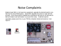
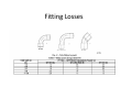
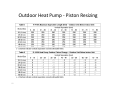
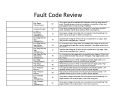
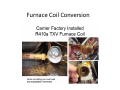
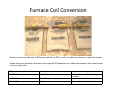
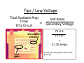
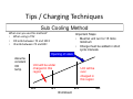
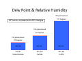
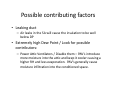
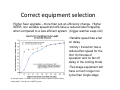
Safety
Always observe the Manufacturers Safety
Precautions and Warning Tags
• Read and follow all safety instructions given in
the manufacturer's installation instructions.
• Always turn off the main power to a system
before making any repairs. There may be more
than one disconnect switch. If applicable, turn
off the accessory power.
• Tag and lock out all disconnect switches.
Safety
Always observe the Manufacturers Safety
Precautions and Warning Tags
• Always remove rings, watches, and other jewelry to
lesson the chance of electrical shock.
• When taking voltage or continuity measurements on a
compressor in a pressurized system, do not take the
measurement directly at the compressor terminals.
– Disconnect the compressor leads at the contactor to take the
measurements.
Noise Complaints
INSTALLATION RECOMMENDATIONS
NOTE: In some cases noise in the living area has been traced to gas pulsations from improper
installation of equipment.
1. Locate unit away from windows, patios, decks, etc. where unit operation sound may disturb
customer.
2. Ensure that vapor and liquid tube diameters are appropriate for unit capacity.
3. Run refrigerant tubes as directly as possible by avoiding unnecessary turns and bends.
4. Leave some slack between structure and unit to absorb vibration.
5. When passing refrigerant tubes through the wall, seal opening with RTV or other pliable silicon-based caulk.
(See Fig. 1.)
6. Avoid direct tubing contact with water pipes, duct work, floor joists, wall studs, floors, and walls.
7. Do not suspend refrigerant tubing from joists and studs with a rigid wire or strap which comes in
direct contact
with tubing. (See Fig. 1.)
8. Ensure that tubing insulation is pliable and completely surrounds vapor tube.
9. When necessary, use hanger straps which are 1 in. wide and conform to shape of tubing insulation.
(See Fig. 1.)
10. Isolate hanger straps from insulation by using metal sleeves bent to conform to shape of insulation.
Noise Complaints
• Operational vibration could indicate a charge issue.
• Verify charge and ensure proper piping and
structural penetration insulation.
• Tubing that is too rigid to building rafters without
proper insulation could transfer noise throughout the
structure.
• On some occasions a sound dampener or
mass weight (RCD part no. 328209--751) placed on
the
vibrating tubing has been known to reduce this noise.
• Utilizing compressor split post grommets (see Fig)
may
also reduce this vibration if piping cannot be
remedied.
Split Post Grommet part number: KA75UG100
Noise Complaints
• An operational high pitch frequency or “waa
waa” sound that appears to resonate through
the suction line could indicate a need to add
more flex or muffling in the lines.
• This has been occasional in scroll compressor
applications and is usually remedied by adding
a field--fabricated suction line loop.
• Reciprocating compressors may
have a noticeable discharge pulsation that
could be remedied with a field installed
discharge muffler.
• Recommend loop by continuous tubing with
no more than 12 inches vertical and 6 inch
horizontal loop.
Noise Complaints
Enable Quiet Shift or (for lower tier equipment) upgrade the defrost board to one
that has the Quiet Shift feature. Quiet Shift Upgrade document to help with the
process. Once Quiet Shift is enabled the compressor will stop for 30 seconds at
defrost initiation and termination to prevent this noise. If defrost board is
upgraded, please send me or your TM the complete model and serial so I can
report it
Quiet Shift
Upgrade.pdf
Noise Complaints
• Nuisance “moose call” noise
from HP going in/out of defrost.
•
Part number EF17BZ251
• Field Solution
• Replace With
• EF17BZ252
– Developing repeatable test to
replicate the noise, each and every
time
– Supplier of reversing valve has
visited and verified the noise.
– Working to isolate the root cause of
the moose call from a component
to system solution.
– Issue appears to be a flow related
noise that occurs after the mid
point of the shift coming out of
defrost.
Reversing Valve Troubleshooting
Light Commercial Split
A Bi-Flow kit must be added to the LLSV to convert them to heat pump operation.
Ordering Number
Liquid Line Size
Mfg Part Number
Used on
Sight Glass
EF680033
3/8”
ALC-066208
AUQ07, 575Jx07,
CHS07
HMI-1TT3
EF680034
1/2”
ALC066209
AUQ08-12, 575Jx08-12,
CHS091-121
HMI-1TT4
EF680037
Solenoid Coil Assy
AMG-24/5060
All units
EF680039
Bi-Flow Kit
ALC066224
All Heat Pumps
SuperHeat
Normal / 5-20˚
10psig = 4.3˚ (average based on SST range/29.5˚-55.1˚)
Fitting Losses
Outdoor Heat Pump - Piston Resizing
12
Outdoor Heat Pump Unit - Piston Resizing
13
Fault Code Review
Fault Code Review
Using Nitrogen Is Not Optional
•Use of nitrogen
during brazing
Carbon deposits resulting from not
using nitrogen
during brazing
16
Brazing
• Purge with nitrogen while brazing
• Nitrogen prevents carbon that can be washed
with POE oil and can cause restrictions and
oil decomposition
17
Part# UNF3 / $55.00
FB4CNF018-060 & piston use
DSB 10-0008 provides most of the information needed to answerer these questions.
DSB 10-0008.pdf
This document is the highlight slide from the Spring Update class on the FB4C.
FB4 Update Class
Slide.pdf
Picture examples of the indoor (cooling) and outdoor (heating) pistons. Notice the note on the
bottom of slide 1 (You may use FB4C’s as a R-22 fan coil replacement by removing the R410a
piston and re-installing the R-22 piston that was in the old Carrier, Bryant or Payne fan coil.)
FB4C_Piston
Models.pdf
FB4CNF018-060 & piston use
Current Super Heat chart for use with a cooling piston as the older slide charts are not compatible
with the current product.
New_HP_Superh
eat_Chart.doc
Part number and drill size of old style and new style pistons
Piston_Models.xls
Additional outdoor units (including piston size) approved to be used with the FB4C, with a piston,
since the release of DSB10-0008.
Pistons by
model_05_08_2010.xl...
Remember to always check PD for proper matches and ratings.
Furnace Coil Conversion
Furnace Coil Conversion
Convert a current production 410A furnace coil back to R22 in order to satisfy a customers in warranty request.
Action: Reuse the old piston that was in the original R22 evaporator coil. Solder the equalizer tube closed at the
suction header tube.
RCD part numbers :
Description
Usage location
324177-701
Adapter Assembly
318289-301
Tube / Body Coupling Adapter
Attach to the new 410A distributor
assembly
Body to hold the piston
311682-201
Adapter
Piston retainer & liquid line connection
Furnace Coil Conversion
Useful Service Manuals
Residential
Residential 2009
Piping - Long...
Fan Coil Service
Manual 6sm.pd...
Mobile Home
HP-AC Small Packag...
Light Commercial
48TC 15-25 Ton
Service Manual....
50TC 3-10 Ton
Service Manual.p...
50TCQ 3-8.5
Ton Service Manual...
Res Split HP-AC
Service Manual...
Review
Tips / Low Voltage
Multi-Voltage Transformer
Check to see that the Control Transformer
Primary Connection is tapped for the correct voltage
When tapped for the
wrong primary:
Secondary voltage and
/ or Current will be
effected!
Tips / Low Voltage
Total Available Amp
Draw
Of a Circuit
=
SECONDARY
VOLTAGE
VOLT
AMPS
Volt Amps
Secondary Voltage
75 V.A.
24 VAC
=
3.125 Amps
Actual operating VAC will be more
accurate.
Tattle Tales
• Parts to make your own can be purchased at
Radio Shack
– 1 ¼” X ¼” in-line fuse holder
– 1 ¼” X ¼” glass fuse
• Measure the circuit current to determine fuse
size
Tips / Air, Acid, & Moisture
Vacuum Pump Maintenance
• The oil used in a vacuum pump can quickly
become contaminated. On average it should
be changed after every 10 hours of operation
or immediately after evacuating a wet or
contaminated system.
• All quality vacuum pumps have a gas ballast
that should be opened during the early stages
of an evacuation.
Tips / Charging Techniques
Weigh in Method
When can you use this method?
Anytime
What is the unit charged for from the factory?
15 feet
How much do you add per foot of line set?
.6 oz/ft Note: 16 oz/lb
Note: You must be using the standard line set size for the unit and not have
greater than 80 ft EL of tubing. Otherwise this method will not be
accurate.
Example:
You have unit with 60 ft of line set (assume proper diameters). How much charge
should be added?
60 ft – 15 ft = 45 ft
45 ft x .6 oz/ft = 27 oz.
27oz. X 1 lb/16oz. = 1.69 lbs
Tips / Charging Techniques
Sub Cooling Method
When can you use this method?
• When using a TXV
• OD amb between 70 and 100 F
• ID amb between 70 and 80 F
Important Steps
• Must let unit run for 15 mins
minimum
• Charge must be added in short
cycle intervals.
Opening of valve
Assume
constant
OD
temp
Unit will be under
charged in this
region
60 F
Unit will be
over
charged in
this region
70 F
80 F
ID Ambient
90 F
Fan Coil Conversion
Don’t forget the Drain Pan Support Bracket
Duct Sweating
-First we need to understand the problem!!
-To resolve sweating we must understand how to
evaluate the problem.
Dew Point
– Dew Point is the temperature at which condensation
forms. When air comes in contact with a surface that is at
or below its Dew Point temperature, condensation will
form on that surface.
– Dew Point calculation?
Duct Sweating
– All this means is that if condensation is
forming, the surface on which it is forming is
below Dew Point.
– To prevent the condensation, the surface must
be above Dew Point
– Dew Point in a attic can easily be above 80°
– Can the insulation surface temperature be
below 80°? YES!!
Dew Point & Relative Humidity
130 grains/pound
DP can be constant while RH changes
121 Degrees
130 grains/pound
97 Degrees
130 grains/pound
75 Degrees
DP=74°
DP=74°
DP=74°
100 RH
50% RH
25% RH
Inside structure
Outside
In Attic
Duct Sweating
Dew Point Table
% Relative Humidity
Air Temp °F
110
105
100
95
90
85
80
75
70
65
60
55
50
45
40
35
32
100 95 90 85 80 75 70 65 60 55 50 45 40 35 30
110 108 106 104 102 100 98 95 93 90 87 84 80 76 72
105 103 101 99 97 95 93 91 88 85 83 80 76 72 67
100 99 97 95 93 91 89 86 84 81 78 75 71 67 63
95 93 92 90 88 86 84 81 79 76 73 70 67 63 59
90 88 87 85 83 81 79 76 74 71 68 65 62 59 54
85 83 81 80 78 76 74 72 69 67 64 61 58 54 50
80 78 77 75 73 71 69 67 65 62 59 56 53 50 45
75 73 72 70 68 66 64 62 60 58 55 52 49 45 41
70 68 67 65 63 61 59 57 55 53 50 47 44 40 37
65 63 62 60 59 57 55 53 50 48 45 42 40 36 32
60 58 57 55 53 52 50 48 45 43 41 38 35 32
55 53 52 50 49 47 45 43 40 38 36 33 32
50 48 46 45 44 42 40 38 36 34 32
45 43 42 40 39 37 35 33 32
40 39 37 35 34 32
35 34 32
32
25
65
62
58
54
49
45
40
36
32
20
60
55
52
48
43
38
35
32
15
51
47
44
40
36
32
32
10
41
37
32
32
32
Insulation required to prevent
condensation
Possible contributing factors
• Low airflow / causes a cold coil and Low SAT
– Zoning bypass open for long periods can cause the same
• Low insulation R-value
–
–
–
–
–
Wet insulation
Wrap not properly installed / to tight
Wrap the supply plenum and add duct liner
Wrap the fan/coil
Use mesh hanging material under duct wrap and seal penetration with
mastic
– Hanging duct helps with evaporation and insulation compression
• If attic temp is high and RH is low, evaporation helps prevent duct
sweating
– Install duct wrap over damper actuators
Possible contributing factors
• Leaking duct
– Air leaks in the SA will cause the insulation to be well
below DP
• Extremely high Dew Point / Look for possible
contributors:
– Power Attic Ventilators / Disable them – PAV’s introduce
more moisture into the attic and keep it cooler causing a
higher RH and less evaporation. PAV’s generally cause
moisture infiltration into the conditioned space.
Sweating Bottom Line
– Hotter is better. The hotter the attic, the warmer
the surface temperatures and the lower the RH.
• Warmer surface temperatures – less likely to be below
Dew Point
• Lower RH – Better chance for condensation to
evaporate.
• Hanging duct helps, so don’t lay it on the attic floor!
Problems When Resizing Equipment
• Customer perceptions—“Why do I have 3 tons when my
neighbor has 5 tons?” Opportunity
Explain longer run cycle = better life, efficiency, and humidity
control @ a higher set point
• Customer complaint—“Why is my equipment running so
long? Its never done that before.”
Must be explained Pre-sale
• Greater vulnerability to poorly installed systems - duct
leakage, improper refrigerant charge, or low airflow.
• Higher recovery times from deep setbacks - instruct
customers to “set & forget” thermostats.
Correct equipment selection
Higher Seer upgrade – more than just an efficiency change. Higher
SEER, non variable speed fan/coils have a reduced latent capacity
when compared to a less efficient system. (bigger-warmer evap coil)
•Variable speed has a fan
on delay
•Infinity / Evolution has a
reduced fan speed for the
first 10 minutes of
operation and no fan off
delay in the cooling mode
•Two stage equipment will
have a much longer run
cycle than single stage
On average it takes a 13 SEER system 10–15 minutes to obtain full latent capacity,
Compared to 5-7 minutes for a 10SEER system
No load humidity control
• Supplemental dehumidification system
– Used to control indoor humidity when there is no
sensible load.
• Cool, cloudy, and/or rainy days. Also at night.
– A better option than lowering the cooling set
point
• This will actually raise the RH and cause possible
condensation of the structure