1
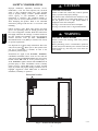
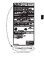
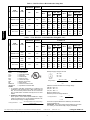
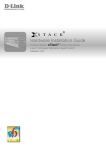
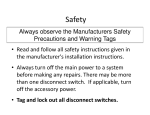
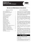
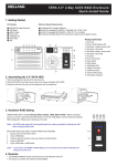
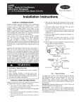
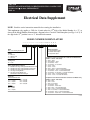
580J*16D SINGLE PACKAGE ROOFTOP, GAS HEATING/ELECTRIC COOLING UNIT WITH PURONR (R-- 410A) REFRIGERANT SIZE: 16 Electrical Data Supplement NOTE: Read the entire instruction manual before starting the installation This supplement only applies to 580J size 16 units when the 13th digit of the Model Number is a “3”, as shown in the Model Number Nomenclature diagram below. Check the Unit Nameplate (see Figs. 1 & 2). If the digit in the 13th position is not a “3” discard this document. MODEL NUMBER NOMENCLATURE 1 2 3 4 5 6 7 8 9 10 11 12 13 14 15 16 17 5 8 0 J E 1 6 D 2 Model 580J = Gas Heating Rooftop Unit Voltage E = 460-3-60 P = 208/230-3-60 T = 575-3-60 Cooling Tons 16 = 15 ton Refirg. System/Gas Heat Options A = Standard One Stage Cooling Models/Natural Gas Heat B = Standard One Stage Cooling Models/Low NOx Heat C = Standard One Stage Cooling Models/SS HX Heat D = Two Stage Cooling Models F = Two Stage Cooling Models and Stainless Steel Gas Heat Exchanger Heat Level Standard/Stainless Steel 072 = 72,000 224 115 = 115,000 240 150 = 150,000 250 180 = 180,000 350 Low Nox 060 = 60,000 090 = 90,000 120 = 120,000 = = = = 224,000 240,000 250,000 350,000 4 0 A 3 A 0 A A Indoor Fan Options 1 = Standard Static Option 2 = Medium Static Option 3 = High Static Option Coil Options For Round Tube/Plate Fin Condenser Coil Models Only (Outdoor – Indoor – Hail Guard) A = Al/Cu – Al/Cu B = Precoat Al/Cu – Al/Cu C = E-coat Al/Cu – Al/Cu D = E-coat Al/Cu – E-Coat Al/Cu E = Cu/Cu – Al/Cu F = Cu/Cu – Cu/Cu M = Al/Cu – Al/Cu – Louvered Hail Guards N = Precoat Al/Cu – Al/Cu – Louvered Hail Guards P = E-coat Al/Cu – Al/Cu – Louvered Hail Guards Q = E-coat Al/Cu – E-coat Al/Cu – Louvered Hail Guards R = Cu/Cu – Al/Cu – Louvered Hail Guards S = Cu/Cu – Cu/Cu – Louvered Hail Guards Coil Options For All Aluminum-Novation Condenser Coil Models Only (Outdoor – Indoor – Hail Guard) G = Al/Al – Al/Cu H = Al/Al – Cu/Cu J = Al/Al – E-coat Al/Cu K = E-coat Al/Al – Al/Cu L = E-coat Al/Al – E-coat Al/Cu T = Al/Al – Al/Cu – Louvered Hail Guards U = Al/Al – Cu/Cu – Louvered Hail Guards V = Al/Al – E-coat Al/Cu – Louvered Hail Guards W = E-coat Al/Al – Al/Cu – Louvered Hail Guards X = E-coat Al/Al – E-coat Al/Cu – Louvered Hail Guards C11016 SAFETY CONSIDERATIONS ! 580J*16D Improper installation, adjustment, alteration, service, maintenance, or use can cause explosion, fire, electrical shock or other conditions which may cause personal injury or property damage. Consult a qualified installer, service agency, or your distributor or branch for information or assistance. The qualified installer or agency must use factory-- authorized kits or accessories when modifying this product. Refer to the individual instructions packaged with the kits or accessories when installing. CAUTION ELECTRICAL HAZARD Failure to follow this caution may result in personal injury or product and property damage. The electrical data contained in this document is only for use with 48TC size 16 units which display a “3” in the 13th position of the 17 digit model number as displayed on the unit’s nameplate. See Fig. 1 for location of the unit’s nameplate. See Fig. 2 for details of the 17 digit model number. Follow all safety codes. Wear safety glasses and work gloves. Use quenching cloths for brazing operations and have a fire extinguisher available. Read these instructions thoroughly and follow all warnings or cautions attached to the unit. Consult local building codes and appropriate national electrical codes (in USA, ANSI/NFPA70, National Electrical Code (NEC); in Canada, CSA C22.1) for special requirements. ! WARNING ELECTRICAL SHOCK HAZARD Failure to follow this warning could cause personal injury or death. Before performing service or maintenance operations on unit, always turn off main power switch to unit and install lockout tag. Unit may have more than one power switch. It is important to recognize safety information. This is the . When you see this symbol on the safety-- alert symbol unit and in instructions or manuals, be alert to the potential for personal injury. Understand the signal words DANGER, WARNING, CAUTION, and NOTE. These words are used with the safety-- alert symbol. DANGER identifies the most serious hazards which will result in severe personal injury or death. WARNING signifies hazards which could result in personal injury or death. CAUTION is used to identify unsafe practices, which may result in minor personal injury or product and property damage. NOTE is used to highlight suggestions which will result in enhanced installation, reliability, or operation. Nameplate Location Fig. 1 - Location of Unit Nameplate 2 C11014 580J*16D 580JE16D240A3A0AA Model Number 5 8 0 J E 1 6D2 4 0 A 3 A 0 AA 1 2 3 4 5 6 7 8 9 10 11 12 13 14 15 16 17 Position of Digit Fig. 2 - Example of Nameplate with Model Number 3 C11017 Table 1 – Unit Wire/Fuse or HACR Breaker Sizing Data UNIT COMBUSTION FAN MOTOR NOM. V ---Ph---Hz IFM TYPE POWER EXHAUST NO C.O. or UNPWR C.O. NO P.E. FLA FLA MCA FUSE or HACR BRKR 68.3 80 STD 580J*16D 208/230---3---60 460--- 3--- 60 MED FLA LRA 71 396 72.1 80 DISC. SIZE FLA LRA 76 400 70.8 80 74 413 74.6 90 79 417 77.8/75.8 100/100 82/80 424 81.6/79.6 100/100 87/84 428 STD 34.0 45 35 234 35.8 45 37 236 35.0 45 37 243 36.8 45 39 245 38.2 50 40 248 40.0 50 42 250 26.5 30 28 184 30.3 40 32 188 26.5 30 28 184 30.3 40 32 188 29.8 35 31 187 33.6 40 36 191 MED 0.48 3.8 0.25 1.8 STD 580J*16D MCA FUSE or HACR BRKR DISC. SIZE HIGH HIGH 575--- 3--- 60 w/ P.E. (pwrd fr/ unit) MED 0.24 3.8 HIGH Table 1 — Unit Wire/Fuse or HACR Breaker Sizing Data (cont) UNIT COMBUSTION FAN MOTOR NOM. V ---Ph---Hz 208/230---3---60 IFM TYPE POWER EXHAUST NO P.E. FLA FLA MCA MCA FUSE or HACR BRKR DISC. SIZE FLA LRA DISC. SIZE FLA LRA 73.1 80 77 401 76.9 100 81 405 75.6 100 80 418 79.4 100 84 422 82.6/80.6 100/100 88/85 429 86.4/84.4 100/100 92/90 433 36.2 45 38 236 38.0 50 40 238 37.2 50 39 245 39.0 50 41 247 40.4 50 43 250 42.2 50 45 252 28.2 35 30 186 32.0 40 34 190 28.2 35 30 186 32.0 40 34 190 31.5 40 33 189 35.3 45 38 193 0.48 3.8 MED 0.25 1.8 HIGH STD 575--- 3--- 60 w/ P.E. (pwrd fr/ unit) STD STD 460--- 3--- 60 FUSE or HACR BRKR MED HIGH 580J*16D w/ PWRD C.O. MED 0.24 3.8 HIGH Legend and Notes for Table 1 LEGEND: BRKR --- Circuit breaker CO --- Convenience outlet DISC --- Disconnect FLA --- Full load amps IFM --- Indoor fan motor LRA --- Locked rotor amps MCA --- Minimum circuit amps PE --- Power exhaust PWRD CO --- Powered convenient outlet UNPWR CO --- Unpowered convenient outlet NOTES: 1. In compliance with NEC requirements for multimotor and combination load equipment (refer to NEC Articles 430 and 440), the overcurrent protective device for the unit shall be fuse or HACR breaker. Canadian units may be fuse or circuit breaker. 2. Unbalanced 3-Phase Supply Voltage Never operate a motor where a phase imbalance in supply voltage is greater than 2%. Use the following formula to determine the percentage of voltage imbalance. % Voltage Imbalance = 100 x max voltage deviation from average voltage average voltage 2011 Bryant Heating and Cooling Systems. D 7310 W. Morris St. D Indianapolis, IN 46231 Example: Supply voltage is 230-3-60 AB = 224 v BC = 231 v AC = 226 v Average Voltage = (224 + 231 + 226) 3 = 681 = 3 227 Determine maximum deviation from average voltage. (AB) 227 – 224 = 3 v (BC) 231 – 227 = 4 v (AC) 227 – 226 = 1 v Maximum deviation is 4 v. Determine percent of voltage imbalance. % Voltage Imbalance = 100 x 4 227 = 1.76% This amount of phase imbalance is satisfactory as it is below the maximum allowable 2%. IMPORTANT: If the supply voltage phase imbalance is more than 2%, contact your local electric utility company immediately. Printed in U.S.A. Edition Date: 01/11 Manufacturer reserves the right to change, at any time, specifications and designs without notice and without obligations. 4 Catalog No: SS580J---02 Replaces: New