1
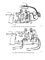
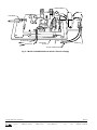
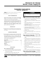
Electronic Air Cleaner
120-60-1 Power Supply Kit
Cancels: IIK 901K-12-5
IIK 901K-12-7
7-95
Installation Instructions
Part No. 322044-701
NOTE: Read the entire instruction manual before starting the
installation.
→ This symbol indicates a change since the last issue.
SAFETY CONSIDERATIONS
Recognize safety information. This is the safety-alert symbol
.
When you see this symbol on the unit and in instructions or
manuals, be alert to the potential for personal injury.
Understand the signal words DANGER, WARNING, and CAUTION. These words are used with the safety-alert symbol. DANGER identifies the most serious hazards which will result in severe
personal injury or death. WARNING signifies a hazard which
could result in personal injury or death. CAUTION is used to
identify unsafe practices which would result in minor personal
injury or product and property damage.
Use care when attaching wires or bus bar to the new power
supply to avoid damaging terminals and/or printed-circuit
board.
Step 2—Install New Power Supply in Model 31MB or
907A
1. Cut terminal ends off wires disconnected from failed power
supply and strip 1/2 in. insulation from wires.
2. Using 4 sheet-metal screws provided in kit, install new power
supply.
3. Choose proper length bus bar (2-3/16 in.) and assemble angle
bracket to bus bar. (See Fig. 1.)
4. Using machine screw and nut, attach existing surge resistor to
angle bracket. (See Fig. 1.)
5. Attach bus bar to high-voltage terminal of power supply.
INTRODUCTION
→ This instruction covers the installation of power supply kit Part No.
322044-701 in an electronic air cleaner with a 120v-60Hz-1 phase
power supply.
→ The
kit is designed to replace both current and previous design
power supplies for duct-mounted models only. See Step 2 for
models 31MB and 907A; see Step 3 for models 31MM, 31MP,
901A and B also 907B and C; see Step 4 for models 31SX, 120v
31KAX, 901E and G, 120v 901KAX; see Step 5 for 240v models
31SX, 31KAX, 901E, 901KAX, and 901G.
The kit contains the following items:
1
1 each
4
4
2
1
1
1
1
INSTALLATION
Step 1—Remove Power Supply
→
1. Turn off main electrical supply to air cleaner and air handler.
2. Remove power door from air cleaner. Remove inside of door
to expose the power supply.
3. Disconnect existing wires from existing power supply.
4. Remove existing power supply from power door.
7. Route wires so they will not contact high-voltage circuit and
install wire clip.
8. Reinstall power door in air cleaner.
9. Turn on main electrical supply to the air cleaner and air
handler.
DESCRIPTION AND USAGE
Power supply
Busbar assembly (2-3/16 in., 4-13/16 in., and 8-1/2 in.)
Wirenut
Phillips-head sheet-metal screw
6-32 machine screw
Hex nut
Wire clip
Angle bracket
Installation Instructions
6. Using wire nuts provided in kit, splice wires. Violet wire can
attach to either red wire. (See Fig. 1.)
10. Check air cleaner for proper operation before leaving job.
→ Step
3—Install New Power Supply in Models 31MM,
31MP, 901A and B, also 907B and C
1. Using 4 sheet-metal screws provided in kit, install new power
supply.
2. Cut terminal ends off wires disconnected from failed power
supply and strip 1/2 in. of insulation from wire. Splice wires
to new power supply wires with wire nuts provided in kit. (See
Fig. 1.)
3. Remove existing surge resistor, if applicable, and discard.
Surge resistor is an integral part of the new power supply.
4. Install proper length bus bar.
5. Route wires so they will not contact high-voltage circuit and
install wire clip.
6. Reinstall power door in air cleaner.
7. Turn on main electrical supply to the air cleaner and air
handler.
8. Check air cleaner for proper operation before leaving the job.
→ Step
4—Install of New Power Supply in 120v Models
31KAX, 31SX, 901E and G, and 901KAX
1. Using 4 sheet-metal screws provided in kit, install new power
supply.
Manufacturer reserves the right to discontinue, or change at any time, specifications or designs without notice and without incurring obligations.
Book 1 4
PC 101
Catalog No. 533-104
Printed in U.S.A.
Form 31KAX-11SI
Pg 1
7-95
Replaces: 31KAX-6SI
Tab 7a 9a
TYPICAL WIRENUT
(WHEN REQUIRED)
WIRE CLIP
BLK
RED OR
VIO
EXISTING
WIRES
WHT
RED
RED
WHT
EXISTING SURGE
RESISTOR
BLK
VIO
BUSBAR
GND
A95271
Fig. 1—Models 31MB, 31MM, 31MP, 31SX, 907A, 901A/B, 901E/G, 907B/C with 120-60-1 Electrical Supply
2. Remove wires from power supply and discard.
3. Connect existing wires and bus bar for models 31SX and 901E
also G. (See Fig. 2.) Do the same for models 31KAX and
901KAX. (See Fig. 4.)
3. Connect existing wires and busbar for models 31SX and 901E
also G. (See Fig. 1.) Do the same for models 31KAX and
901KAX. (See Fig. 3.)
4. Reinstall power door in air cleaner.
4. Reinstall power door in air cleaner.
5. Turn on main electrical supply to air cleaner and air handler.
5. Turn on main electrical supply to air cleaner and air handler.
6. Check air cleaner for proper operation before leaving job. If
the unit fails to operate, check for faulty transformer.
6. Check air cleaner for proper operation before leaving job.
Step 5—Install New Power Supply in 240v Models
31KAX, 31SX, 901E also G, and 901KAX
1. Using 4 sheet-metal screws provided in kit, install new power
supply.
2. Remove and discard wires from power supply.
2
WIRE TIE
YEL
BLK
VIO
RED
BLK
BLK
BUSBAR
YEL
YEL
VIO
GND
A95272
Fig. 2—Models 31SX, 901E, and 901G with 240-60-1 Electrical Supply
BUSBAR
BLUE/SILVER
BLK
BLUE/GOLD
WHT
A95273
Fig. 3—Models 31KAX/901KAX with 120-60-1 Electrical Supply
3
TRANSFORMER
BLK
BLK
"Z" BUSBAR
WHT
WHT
BLUE/SILVER
BLUE/GOLD
MOUNTING
PLATE
WHT
BLK
WIRE CLIP
SPLICE CONNECTORS
Fig. 4—Models 31KAX/901KAX with 240-60-1 Electrical Supply
Copyright 1995 Carrier Corporation
901k127
Manufacturer reserves the right to discontinue, or change at any time, specifications or designs without notice and without incurring obligations.
Book 1 4
PC 101
Catalog No. 533-104
Printed in U.S.A.
Form 31KAX-11SI
Pg 4
7-95
Replaces: 31KAX-6SI
Tab 7a 9a