1
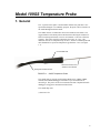
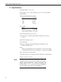
Model 109SS
Temperature Probe
9/08
C o p y r i g h t © 1 9 8 3 - 2 0 0 8
C a m p b e l l S c i e n t i f i c , I n c .
Warranty and Assistance
The MODEL 109SS TEMPERATURE PROBE FOR HARSH
ENVIRONMENTS is warranted by CAMPBELL SCIENTIFIC, INC. to be
free from defects in materials and workmanship under normal use and service
for twelve (12) months from date of shipment unless specified otherwise.
Batteries have no warranty. CAMPBELL SCIENTIFIC, INC.'s obligation
under this warranty is limited to repairing or replacing (at CAMPBELL
SCIENTIFIC, INC.'s option) defective products. The customer shall assume
all costs of removing, reinstalling, and shipping defective products to
CAMPBELL SCIENTIFIC, INC. CAMPBELL SCIENTIFIC, INC. will
return such products by surface carrier prepaid. This warranty shall not apply
to any CAMPBELL SCIENTIFIC, INC. products which have been subjected
to modification, misuse, neglect, accidents of nature, or shipping damage. This
warranty is in lieu of all other warranties, expressed or implied, including
warranties of merchantability or fitness for a particular purpose. CAMPBELL
SCIENTIFIC, INC. is not liable for special, indirect, incidental, or
consequential damages.
Products may not be returned without prior authorization. The following
contact information is for US and International customers residing in countries
served by Campbell Scientific, Inc. directly. Affiliate companies handle
repairs for customers within their territories. Please visit
www.campbellsci.com to determine which Campbell Scientific company
serves your country.
To obtain a Returned Materials Authorization (RMA), contact CAMPBELL
SCIENTIFIC, INC., phone (435) 753-2342. After an applications engineer
determines the nature of the problem, an RMA number will be issued. Please
write this number clearly on the outside of the shipping container.
CAMPBELL SCIENTIFIC's shipping address is:
CAMPBELL SCIENTIFIC, INC.
RMA#_____
815 West 1800 North
Logan, Utah 84321-1784
For all returns, the customer must fill out a “Declaration of Hazardous Material
and Decontamination” form and comply with the requirements specified in it.
The form is available from our website at www.campbellsci.com/repair. A
completed form must be either emailed to [email protected] or faxed
to 435-750-9579. Campbell Scientific will not process any returns until we
receive this form. If the form is not received within three days of product
receipt or is incomplete, the product will be returned to the customer at the
customer’s expense. Campbell Scientific reserves the right to refuse service on
products that were exposed to contaminants that may cause health or safety
concerns for our employees.
CAMPBELL SCIENTIFIC, INC. does not accept collect calls.
109SS Table of Contents
PDF viewers note: These page numbers refer to the printed version of this document. Use
the Adobe Acrobat® bookmarks tab for links to specific sections.
1. General .........................................................................1
1.1 Specifications............................................................................................2
2. Accuracy.......................................................................3
3. Installation and Wiring ................................................4
3.1 Burial ........................................................................................................4
3.2 Submersion ...............................................................................................4
4. Wiring............................................................................4
5. Programming ...............................................................4
5.1 CRBasic ....................................................................................................5
5.1.1 CRBasic Examples..........................................................................5
5.1.1.1 Sample Program for CR200 Series Datalogger.....................6
5.1.1.2 Example 2. Sample Program for CR1000 Datalogger .........6
5.1.1.3 Sample Program for CR5000 ................................................7
5.2 Edlog.........................................................................................................7
5.2.1 Example Edlog Program .................................................................7
5.3 Electrical Noisy Environments .................................................................9
5.4 Long Lead Lengths...................................................................................9
6. Measurement Details.................................................10
7. Maintenance and Calibration....................................11
8. Troubleshooting ........................................................11
Figures
1-1.
2-1.
2-2.
6-1.
109SS Temperature Probe.......................................................................1
Steinhart and Hart....................................................................................3
Possible Errors.........................................................................................3
109SS Thermistor Probe Schematic......................................................10
Tables
4-1. Connections to Campbell Scientific Dataloggers ....................................4
5-1. Wiring for Example Programs ................................................................5
5-2. Wiring for Example Program ..................................................................7
i
Model 109SS Temperature Probe
1. General
The –L portion of this probe’s model number indicates the probe has a userspecified lead length. For readability purposes, the probe will be referred to as
the 109SS throughout this document.
The 109SS consists of a thermistor encased in a stainless-steel sheath. The
rugged stainless-steel sheath protects the thermistor allowing the 109SS to be
buried or submerged in harsh, corrosive environments. It also has a fast time
response. This probe measures temperature from -40°C to +70°C. The
thermistor can survive temperatures up to 100°C, but the overmolded joint and
cable should not be exposed to temperatures greater than +70°C (see Figure
1-1).
Overmolded Joint
Thermistor Encased in
Stainless-Steel Sheath
Santoprene-Jacketed Cable
FIGURE 1-1. 109SS Temperature Probe
The 109SS probe is typically used with the CR200-series, CR800, CR850,
CR1000, and CR3000 dataloggers which have a special instruction for
measuring it. The probe can also be measured with other Campbell Scientific
dataloggers using generic measurement instructions.
The 109SS ships with:
(1) Resource CD
1
Model 109SS Temperature Probe
1.1 Specifications
Temperature Range: -40° to +70°C
Survival Range: -50° to +100°C (thermistor); -50°C to +70°C (overmolded
joint and cable)
Thermistor Interchangeability Tolerance:
Temperature
Tolerance
-40°C
±0.6°C
0°C
±0.38°C
25°C
±0.1°C
50°C
±0.3°C
70°C
±0.45°C
Time Constant:
Fluid
Still Air
Air @ 3 meter/second
Antifreeze/Water Rolling
τ
31 seconds
7.5 seconds
0.5 seconds
Water submersion depth: 50 feet (21 psi)
Linearization Error: Steinhart & Hart equation; maximum error is 0.02°C
at -40°C.
Maximum Lead Length: 1000 ft
Other Information:
Thermistor: BetaTherm - Micro-BetaCHIP Probe 10K3MCD1 0.018"
diameter, 10Kohms at 25 C
Probe:
stainless steel sheath 0.063 inch (0.16 cm) diameter, 2.3 inch (5.84 cm) length
overmolded joint 0.40 inch (1.02 cm) diameter, 1.67 inch (4.24 cm) length
Cable: Santoprene 0.220 inch diameter
Cable/probe connection: "ATUM" heat shrink, "Macromelt" overmolded joint
Weight: 0.2 lbs/10 1/2 ft cable
NOTE
2
The black outer jacket of the cable is Santoprene® rubber. This
compound was chosen for its resistance to temperature extremes,
moisture, and UV degradation. However, this jacket will
support combustion in air. It is rated as slow burning when
tested according to U.L. 94 H.B. and will pass FMVSS302.
Local fire codes may preclude its use inside buildings.
Model 109SS Temperature Probe
2. Accuracy
The overall probe accuracy is a combination of the thermistor's interchangeability
specification and the accuracy of the bridge resistor. The Steinhart and Hart
equation used to calculate temperature has a negligible error (Figure 2-1). In a
"worst case" the errors add to an accuracy of ±0.6°C over the range of -40° to 70°C
and ±0.49°C over the range of -20°C to 70°C. The major error component is the
interchangeability specification (tolerance) of the thermistor. The bridge resistor
has a 0.1% tolerance with a 10 ppm temperature coefficient. Figure 2-2 shows the
possible worst case probe and measurement errors.
Steinhart & Hart - Tabulated values
0.03
0.025
Error Degrees C
0.02
0.015
0.01
0.005
0
-50
-40
-30
-20
-10
0
10
20
30
40
50
60
70
-0.005
Temperature Degrees C
FIGURE 2-1. Steinhart and Hart
FIGURE 2-2. Possible Errors
3
Model 109SS Temperature Probe
3. Installation and Wiring
3.1 Burial
The 109SS is suitable for shallow burial only. It should be placed horizontally
at the desired depth to avoid thermal conduction from the surface to the
thermistor. Placement of the cable inside a rugged conduit may be advisable
for long cable runs, especially in locations subject to digging, mowing, traffic,
use of power tools, or lightning strikes.
3.2 Submersion
The 109SS can be submerged to 50 ft. Please note that the 109SS is not
weighted. Therefore, the installer should either add a weighting system or
secure the probe to a fixed or submerged object such as a piling.
4. Wiring
Connections to Campbell Scientific dataloggers are given in Table 4-1.
Temperature is measured with one Single-Ended input channel and a Voltage
Excitation channel. Multiple probes can be connected to the same excitation
channel (the number of probes per excitation channel is physically limited by
the number of lead wires that can be inserted into a single voltage excitation
terminal, approximately six).
TABLE 4-1. Connections to Campbell Scientific Dataloggers
CR200
CR800
CR850
CR3000
CR1000
CR510
CR500
CR10(X)
CR5000
21X
CR7
CR23X
Color
Description
Black
Excitation
Switched
Voltage
Excitation
Switched
Voltage
Excitation
Switched
Voltage
Excitation
Red
Temperature
Signal
Single-Ended
Input
Single-Ended
Input
Single-Ended
Input
Purple
Signal Ground
AG
Clear
Shield
G
5. Programming
NOTE
4
This section is for users who write their own datalogger
programs. A datalogger program to measure this sensor can be
generated using Campbell Scientific’s Short Cut Program
Builder software. You do not need to read this section to use
Short Cut.
Model 109SS Temperature Probe
The datalogger is programmed using either CRBasic or Edlog. Dataloggers
that use CRBasic include our CR200-series, CR800, CR850, CR1000,
CR3000, CR5000, and CR9000(X); see Section 5.1. Dataloggers that use
Edlog include our CR10, CR10(X), CR23X, and CR7; refer to Section 5.2.
CRBasic and Edlog are included in our LoggerNet, PC400, and RTDAQ
software.
If applicable, please read “Section 5.3—Electrical Noisy Environments” and
“Section 5.4—Long Lead Lengths” prior to programming your datalogger.
Measurement details are provided in Section 6.
5.1 CRBasic
In the CR200-series, CR800, CR850, CR1000, and CR3000 dataloggers,
Instruction Therm109 is used to measure temperature. Therm109 provides
excitation, makes a single ended voltage measurement, and calculates
temperature.
The Therm109 instruction has the following form:
Therm109 (Dest, Repetitions, SE Chan, Ex Chan, Multiplier, Offset)
A multiplier of 1.0 and an offset of 0.0 yields temperature in Celsius. For
Fahrenheit, use a multiplier of 1.8 and an offset of 32. Sections 5.1.1.1 and
5.1.1.2 provide example programs that use the Therm109 instruction.
The CR5000 and CR9000(X) use the BrHalf instruction to read the 109SS’s
resistance. The Steinhart-Hart equation is entered as an expression to convert
the resistance to degrees Celsius (see Section 5.1.1.3).
5.1.1 CRBasic Examples
TABLE 5-1. Wiring for Example
Programs
Color
Description
CR200
CR1000
CR5000
Black
Excitation
EX1 or VX1
Red
Signal
SE1
Purple
Signal Ground
Clear
Shield
5
Model 109SS Temperature Probe
5.1.1.1 Sample Program for CR200 Series Datalogger
'CR200 Series Datalogger
‘This example program measures a single 109SS Thermistor Probe
‘once a second and stores the average temperature every 10 minutes.
‘Declare the variable for the temperature measurement
Public Air_Temp
‘Define a data table for 10 minute averages:
DataTable (AvgTemp,1,1000)
DataInterval (0,10,min)
Average (1,Air_Temp,0)
EndTable
BeginProg
Scan (1 ,sec)
‘Measure the temperature:
Therm109 (Air_Temp,1,1,Ex1,1.0,0)
Call the data table:
CallTable AvgTemp
NextScan
EndProg
5.1.1.2 Example 2. Sample Program for CR1000 Datalogger
'CR1000
'Declare Variables and Units
Public T109_C
Units T109_C=Deg C
'Define Data Tables
DataTable(Table1,True,-1)
DataInterval(0,10,Min,10)
Average(1,T109_C,FP2,False)
EndTable
'Main Program
BeginProg
Scan(1,Sec,1,0)
'Default Datalogger Battery Voltage measurement Batt_Volt:
'109SS Temperature Probe measurement T109_C:
Therm109(T109_C,1,1,1,0,_60Hz,1.0,0.0)
'Call Data Tables and Store Data
CallTable(Table1)
NextScan
EndProg
6
Model 109SS Temperature Probe
5.1.1.3 Sample Program for CR5000
'CR5000
'This example program measures a single 109 Thermistor probe
'once a second and stores the average temperature every 10 minutes.
'Declare the variable for the temperature.
Public Air_Temp
'Declare variables for the raw measurement, thermistor resistance, and ln(resistance):
Dim V_Vx, Rtherm, lnRt
'Define a data table for 10 minute averages:
DataTable (AvgTemp,1,1000)
DataInterval (0,10,min,10)
Average (1,Air_Temp,IEEE4,0)
EndTable
BeginProg
Scan (1 ,sec,5,0)
'Measure the 109 probe. The result is V/Vx:
BrHalf (V_Vx,1,mV5000,3,Vx1,1,5000,True ,0,_60Hz,1.0,0)
'Calculate reistance:
RTherm=24900*(1/V_Vx-1)
'Calculate the natural log of the resistance:
lnRt=Log(Rtherm)
'Apply the Steinhart and Hart equation and convert to degrees C in one step:
Air_Temp=1/(1.129241e-3+2.341077e-4*lnRt+8.775468e-8*(lnRt^3))-273.15
'Call the data table:
CallTable AvgTemp
NextScan
EndProg
5.2 Edlog
In Edlog, Instruction 5 is typically used to measure the 109SS resistance.
Instruction 55 is used to apply the Steinhart and Hart equation. Instruction 55
does not allow entering the coefficients with scientific notation. In order to use
this instruction with as much resolution as possible, the ln resistance term is
pre scaled by 10-3. This allows the first order coefficient (B) to be multiplied
by 103, and the 3rd order coefficient (C) to be multiplied by 109 (see Section
5.2.1).
5.2.1 Example Edlog Program
TABLE 5-2. Wiring for Example Program
Color
Black
Red
Purple
Clear
Description
Excitation
Signal
Signal Ground
Shield
CR10X
E1
SE1
AG
G
7
Model 109SS Temperature Probe
Example Program for CR10X
;{CR10X}
;
*Table 1 Program
01: 1
Execution Interval (seconds)
1: AC Half Bridge (P5)
1: 1
Reps
2: 25
2500 mV 60 Hz Rejection Range
3: 1
SE Channel
4: 1
Excite all reps w/Exchan 1
5: 2500
mV Excitation
6: 1
Loc [ V_Vx
]
7: 1.0
Mult
8: 0.0
Offset
2: Z=1/X (P42)
1: 1
2: 2
X Loc [ V_Vx
Z Loc [ Vx_V
3: Z=X+F (P34)
1: 2
2: -1
3: 3
X Loc [ Vx_V
]
F
Z Loc [ Vx_V_1 ]
4: Z=X*F (P37)
1: 3
2: 24900
3: 4
X Loc [ Vx_V_1 ]
F
Z Loc [ Rtherm ]
]
]
5: Z=LN(X) (P40)
1: 4
X Loc [ Rtherm ]
2: 5
Z Loc [ lnRt
]
6: Z=X*F (P37)
1: 5
2: .001
3: 6
X Loc [ lnRt
]
F
Z Loc [ Scal_lnRt ]
7: Polynomial (P55)
1: 1
Reps
2: 6
X Loc [ Scal_lnRt ]
3: 7
F(X) Loc [ 1_Tk
]
4: .001129
C0
5: .234108
C1
6: 0.0
C2
7: 87.7547
C3
8: 0.0
C4
9: 0.0
C5
8: Z=1/X (P42)
1: 7
2: 8
8
X Loc [ 1_Tk
]
Z Loc [ Tk
]
Model 109SS Temperature Probe
9: Z=X+F (P34)
1: 8
2: -273.15
3: 9
X Loc [ Tk
]
F
Z Loc [ Air_Temp ]
10: If time is (P92)
1: 0
Minutes (Seconds --) into a
2: 10
Interval (same units as above)
3: 10
Set Output Flag High (Flag 0)
11: Real Time (P77)
1: 110
Day,Hour/Minute (midnight = 0000)
12: Average (P71)
1: 1
Reps
2: 9
Loc [ Air_Temp ]
*Table 2 Program
02: 0.0000
Execution Interval (seconds)
*Table 3 Subroutines
End Program
5.3 Electrical Noisy Environments
AC power lines, pumps, and motors, can be the source of electrical noise. If
the 109SS probe or datalogger is located in an electrically noisy environment,
the 109SS probe should be measured with the 60 or 50 Hz rejection option as
shown in the examples in Section 5.1.1.2 and Section 5.2.1.
5.4 Long Lead Lengths
Additional settling time may be required for lead lengths longer than 300 feet,
where settling time is the delay before the measurement is made.
For the CR200-series, CR800, CR850, CR1000, and CR3000, the 60 and 50
Hz integration options include a 3 ms settling time; longer settling times can be
entered into the Settling Time parameter. The example Therm109 instruction
listed below has a 20 mSec (20000 μSec) delay:
‘Therm109 ( Dest, Reps, SEChan, ExChan, SettlingTime, Integ, Mult, Offset )
Therm109(T109_C,1,1,1,20000,_60Hz,1.0,0.0)
In Edlog, use the DC Half Bridge instruction (P4) with a 20 millisecond delay
as shown below. Use P4 in place of P5 in Section 5.2.1 (the instructions that
follow P5 to convert the measurement result to temperature are still required).
9
Model 109SS Temperature Probe
1: Excite-Delay (SE) (P4)
1: 1
Reps
2: 25
2500 mV 60 Hz Rejection Range (Delay must be zero)
3: 1
SE Channel
4: 1
Excite all reps w/Exchan 1
5: 2
Delay (0.01 sec units)
6: 2500
mV Excitation
7: 3
Loc [V_Vx ]
8: .0004
Multiplier
9: 0.0
Offset
6. Measurement Details
Understanding the details in this section are not necessary for general
operation of the 109SS Probe with CSI's dataloggers.
The Therm109 Instruction outputs a 2500 mV excitation and measures the
voltage across the 24.9 K resistor (Figure 6-1). The thermistor resistance
changes with temperature.
EX
BLACK
10K3AI
THERMISTOR
HI
RED
24.9K Ω, 0.1%
AG
G
PURPLE
CLEAR
FIGURE 6-1. 109SS Thermistor Probe Schematic
The measured voltage, V, is:
V = VEX
24,900
24,900 + Rt
Where VEX is the excitation voltage, 24,900 ohms is the resistance of the fixed
resistor and Rt is the resistance of the thermistor
10
Model 109SS Temperature Probe
The resistance of the thermistor is:
⎛V
⎞
Rt = 24,900⎜ EX − 1⎟
⎝ V
⎠
The Steinhart and Hart equation is used to calculate temperature from
Resistance:
TK =
1
A + B ln( RT ) + C (ln( RT ))3
Where TK is the temperature in Kelvin. The Steinhart and Hart coefficients
used in the Therm109 instruction are:
A = 1.129241x10⁻³
B = 2.341077x10⁻⁴
C = 8.775468x10⁻⁸
7. Maintenance and Calibration
The 109SS Probe requires minimal maintenance. Periodically check cabling
for proper connections, signs of damage, and possible moisture intrusion. For
all factory repairs and recalibrations, customers must get a returned materials
authorization (RMA). Customers must also properly fill out a “Declaration of
Hazardous Material and Decontamination” form, and comply with the
requirements specified in it. Refer to the “Warranty and Assistance” page for
more information.
8. Troubleshooting
Symptom: Temperature is NAN, -INF, -9999, -273
Verify the red wire is connected to the correct Single-Ended analog input
channel as specified by the measurement instruction, the black wire is
connected to the switched excitation channel as specified by the measurement
instruction, and the purple wire is connected to datalogger ground.
Symptom: Incorrect Temperature
Verify the multiplier and offset parameters are correct for the desired units
(Section 5). Check the cable for signs of damage and possible moisture
intrusion.
NOTE
For all factory repairs, customers must get an RMA. Customers
must also properly fill out a “Declaration of Hazardous Material
and Decontamination” form and comply with the requirements
specified in it. Refer to the “Warranty and Assistance” page for
more information.
11
Model 109SS Temperature Probe
Symptom: Unstable Temperature
Try using the 60 or 50 Hz integration options, and/or increasing the settling
time as described in Sections 8 and 9. Make sure the clear shield wire is
connected to datalogger ground, and the datalogger is properly grounded.
12
This is a blank page.
Campbell Scientific Companies
Campbell Scientific, Inc. (CSI)
815 West 1800 North
Logan, Utah 84321
UNITED STATES
www.campbellsci.com
[email protected]
Campbell Scientific Africa Pty. Ltd. (CSAf)
PO Box 2450
Somerset West 7129
SOUTH AFRICA
www.csafrica.co.za
[email protected]
Campbell Scientific Australia Pty. Ltd. (CSA)
PO Box 444
Thuringowa Central
QLD 4812 AUSTRALIA
www.campbellsci.com.au
[email protected]
Campbell Scientific do Brazil Ltda. (CSB)
Rua Luisa Crapsi Orsi, 15 Butantã
CEP: 005543-000 São Paulo SP BRAZIL
www.campbellsci.com.br
[email protected]
Campbell Scientific Canada Corp. (CSC)
11564 - 149th Street NW
Edmonton, Alberta T5M 1W7
CANADA
www.campbellsci.ca
[email protected]
Campbell Scientific Ltd. (CSL)
Campbell Park
80 Hathern Road
Shepshed, Loughborough LE12 9GX
UNITED KINGDOM
www.campbellsci.co.uk
[email protected]
Campbell Scientific Ltd. (France)
Miniparc du Verger - Bat. H
1, rue de Terre Neuve - Les Ulis
91967 COURTABOEUF CEDEX
FRANCE
www.campbellsci.fr
[email protected]
Campbell Scientific Spain, S. L.
Psg. Font 14, local 8
08013 Barcelona
SPAIN
www.campbellsci.es
[email protected]
Please visit www.campbellsci.com to obtain contact information for your local US or International representative.