1
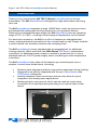
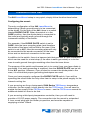
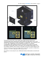
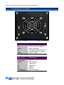
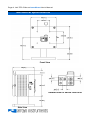
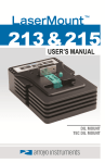
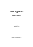
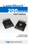
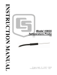
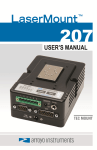
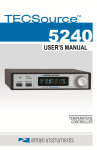
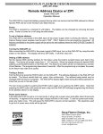
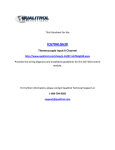
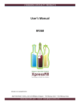
Page 2 · 242 TEC C-Mount LaserMount User’s Manual Introduction Thank you for choosing the 242 TEC C-Mount LaserMount from Arroyo Instruments. The 242 LaserMount is designed for high performance and long term use. The 242 LaserMount integrates a large 120W Peltier cooler for precise control and substantial heating and cooling capacity for your powerful devices. Featuring an integrated nitrogen purge, the 242 LaserMount has an operating range of -5°C to +85°C, covering a broad range of temperature control needs. For electrical connection, the 242 LaserMount features an integrated lead clamp, making electrical connection to the c-mount lead a snap. Simply load the c-mount device into the fixture and turn the clamping knob. The 242 LaserMount comes standard with an integrated fan for additional cooling capacity. When used with the 5300 Series TECSource temperature controllers, no additional power supply is needed to power the fan, or use a standard external 12V DC power supply when connecting to other temperature controllers. The 242 LaserMount also offers all the features you would expect from a modern c-mount laser diode fixture, including: Stainless steel alignment plate for easy device alignment during loading Designed to be quickly integrated with Arroyo’s LaserSource and TECSource instruments. Industry-standard D-sub connectors and pin-outs allow for quick integration into existing laser applications. Banana plug for case ground, which can be used as a wrist strap connection or to assure proper grounding to an optical table or test bench. 242 TEC C-Mount LaserMount User’s Manual · Page 3 Installation and Use The 242 LaserMount setup is very quick, simply follow the directions below. Configuring the mount: The only configuration of the 242 LaserMount is determining if earth ground/case is to be connected to the diode. On the side of the 242, there is a switch labeled DIODE PLATE. When the switch is in the CASE position, then the diode plate is connected to the case (and typically earth ground through the instrument cables) of the fixture. For example, if the DIODE PLATE switch is set to CASE, then the laser mounting plate (and therefore the anode of the laser) will be tied to the case. If the switch is set to N/C, then the mounting plate will only be connected to the anode connection of the laser driver and no electrical connection to the case. In addition to the switch, there is a banana jack that provides a case connection which can be used for a wrist strap (if the case is earth grounded) or to tie the case to earth ground through something other than the laser driver. The purpose of the switch and banana jack is to control how your laser diode is grounded. If no earth grounding is required, then the DIODE PLATE can be left in the N/C position. However, if you to elect to connect the diode plate to the case, it is critical that proper grounding techniques are used. Once you have properly configured the DIODE PLATE switch, if you will be operating the mount then the only other item to setup is the power supply for the internal cooling fan. If you are using an Arroyo Instruments 5300 Series TECSource temperature controller, the fan supply is built directly into the TECSource. You will need to enable the fan supply in the TECSource menu – see the TECSource manual for additional details on how to do that. If you are using a third-party temperature controller, then you will need to provide a 12V DC power supply. The connection into the mount is a standard 2.1mm round plug with the center pin positive, and must be capable of supplying at least 150mA. Page 4 · 242 TEC C-Mount LaserMount User’s Manual Connect to Laser Diode Driver and TEC Controller: Next, connect the 242 LaserMount to your laser diode driver and temperature controller. Make sure the temperature controller’s current limit is set to a maximum value of 7.4A. Where possible, we recommend the use of Arroyo Instruments laser and TEC cables. Use p/n 1262 TECSource Cable for the temperature controller connection, and p/n 1220 LaserSource Cable for the laser connection. NOTE Arroyo Instruments offers Laser and TEC cables designed to connect directly between our LaserSource and TECSource products. If you use your own cables, ensure the connections are properly made between the instrument and the mount, and that proper grounding techniques are used. The pin-out of the connectors can be found later in this document. WARNING Be sure you are properly ESD protected before handling your laser. For additional information, read the section titled “Laser Diode Protection” later in this manual. Mounting your device: Start by turning the knob on the top of the fixture counter-clockwise to open the lead clamp. Make sure the clamp is high enough to allow sufficient space for loading the device. The 242 LaserMount has a stainless steel alignment plate which is there to help properly align the device to the mounting hole and clamping block. Using the alignment plate to guide the device, place the device onto the mount and use the 2-56 x 3/16” screw provided with the fixture to fasten the device to the fixture. After the device has been mounted, tighten the clamp by turning the knob on the top of the fixture clockwise until the lead is help tightly against the clamp block. Do not over-tighten the clamp or you may damage the clamping mechanism. The drawing and two photos below illustrate the unloaded configuration with the clamp all the way open (left), and a device loaded and clamp tightened down on the device lead (right). 242 TEC C-Mount LaserMount User’s Manual · Page 5 The mount comes with a cover plate and nitrogen purge nipple that is recommended when operating the device below the dew point, which is the temperature what which moisture will begin to condensate. This is typically 10°C to 15°C, but is dependent on your laboratory conditions. To prevent condensation, after loading the device, mount the cover plate by using the provided 4-40 flat head screws, and screw in the nitrogen purge nipple (if it is not already installed), then connect a nitrogen source to the input nipple on the side of the mount. A very low nitrogen flow is required to prevent condensation, typically 1 to 2 SCFH (standard cubic feet per hour). Your fixture is now ready for use. Additional technical information can be found below. Page 6 · 242 TEC C-Mount LaserMount User’s Manual Connector Pin-Outs 242 TEC C-Mount LaserMount Rear Connectors DB-9 Pin Description 1&2 No Connection 3 Chassis Ground (GND) 4&5 Laser Cathode 6 Photodiode (PD) Cathode 7 Photodiode (PD) Anode 8&9 Laser Anode Laser DB-9 Connector Pin-Out DB-15 Pin Description 1, 2, & 9 TE (+) 3, 4, & 10 TE (–) 5&6 Earth Ground 7 Thermistor 8 Thermistor 11 FAN (+) 12 FAN (–) 13 thru 15 No Connection TEC DB-15 Connector Pin-Out 242 TEC C-Mount LaserMount User’s Manual · Page 7 Connection Description Tip +12VDC (8 to 12VDC) Sleeve Fan Ground 12V Fan Connector Pin-Out Technical Specifications FICATIONS 242 TEC C-Mount LaserMount LASER PACKAGE SUPPORTED Package TEMPERATURE CONTROL Temperature Range (°C) Sensor Type TE Module INPUT CONNECTORS Laser Diode Temperature Controller Fan Nitrogen GENERAL Recommended nitrogen flow Size without base (H x W x D) [in(mm)] Mounting holes C-mount -5 to +85 BetaTHERM 10K3A1IA 10kΩ Thermistor Imax = 7.4A Vmax = 16.4V Qmax = 78W DB-9, male DB-15, male 2.1mm round, 8 to 12VDC 1/8” barb 1 to 2 SCFH 4.0 (101.6) x 4.0 (101.6) x 3.5 (76.2) Slotted holes for ¼-20 (base) ¼-20 x 2 (for post mount) M6 (for post mount) 4-40 x 4 for nitrogen cover plate Calculating Temperature Using the Steinhart-Hart Formula The thermistor resistance can easily be converted to temperature using the Steinhart-Hart equation, and is expressed as: 1 A B * ln( R) C * ln( R) 3 T Where R is the thermistor resistance in Ohms, and A, B, and C are listed below. Steinhart-Hart Constants for Thermistor Temperature Calculation A 1.129241x10⁻³ B 2.341077x10⁻⁴ C 8.775468x10⁻⁸ Page 8 · 242 TEC C-Mount LaserMount User’s Manual Mechanical Specifications Front View Detailed View of Device Load Area Side View 242 TEC C-Mount LaserMount User’s Manual · Page 9 Laser Diode Protection Electrostatic discharge and current spikes can be a significant cause of damage to laser diodes, but when proper precautions are taken, these risks can be greatly reduced or eliminated. Arroyo Instruments’ controllers offer state-of-art laser diode protection, but no instrument can fully shield the laser from damage. Please take these considerations into account when operating your laser: 1. 2. 3. 4. 5. 6. Always set the current limit at or below the maximum current your laser can handle. This prevents the device from accidentally driving the current too high, either via the set point or from the modulation port. This also provides additional current limiting protection from ESD. Always work in an ESD safe operating environment, including the use of wrist straps, ESD grounded work surfaces and floors, and ESD-safe tools. Where the AC power to the laser driver to temperature controller may be noisy, use isolation transformers or uninterruptible power supplies that provide isolation. Make sure all cables are securely connected and fastening screws are screwed in tight. Do not route power cords or other cables in parallel with the laser or temperature controller cables, as coupling may occur between the cables and inject noise into the laser diode. While it is not possible to create a ground loop through the LaserSource because of it’s isolation of all inputs, it is possible when using other equipment. Ensure that any other equipment is properly isolated to avoid any ground loop problems. Page 10 · 242 TEC C-Mount LaserMount User’s Manual Warranty Arroyo Instruments warrants this product to be free from defects in material and workmanship under normal use and service for a period of one (1) year from date of shipment. It does not apply when the product has been misused, altered or damaged by accident or abnormal conditions of operation. If found to be defective during the warranty period, the product will either be repaired or replaced at Arroyo Instruments's option. THIS WARRANTY IS IN LIEU OF ALL OTHER WARRANTIES, EXPRESSED OR IMPLIED, INCLUDING IMPLIED WARRANTIES OF MERCHANTABILITY OR FITNESS FOR ANY PARTICULAR PURPOSE. ARROYO INSTRUMENTS SHALL NOT BE LIABLE FOR ANY INDIRECT, SPECIAL, OR CONSEQUENTIAL DAMAGES RESULTING FROM THE PURCHASE OR USE OF ITS PRODUCTS. Service and Support For service and support, contact your local distributor or Arroyo Instruments. By mail: By phone: By fax: By email: On the web: Arroyo Instruments 624 Clarion Court San Luis Obispo, CA 93401 USA +1 (805) 543-1302 +1 (805) 543-1303 [email protected] http://www.arroyoinstruments.com 242 TEC C-Mount LaserMount User’s Manual · Page 11 NOTES: Copyright © 2011, Arroyo Instruments. All Rights Reserved P/N 530-1004 Rev E