1
SmartSwitch Router
User Reference Manual
9032578-05
Copyright
© 2000 by Cabletron Systems, Inc. All rights reserved.
Cabletron Systems, Inc.
35 Industrial Way
Rochester, NH 03867-5005
Printed in the United States of America
Changes
Cabletron Systems, Inc., reserves the right to make changes in specifications and other information
contained in this document without prior notice. The reader should in all cases consult Cabletron
Systems, Inc., to determine whether any such changes have been made.
The hardware, firmware, or software described in this manual is subject to change without notice.
Disclaimer
IN NO EVENT SHALL CABLETRON SYSTEMS BE LIABLE FOR ANY INCIDENTAL, INDIRECT,
SPECIAL, OR CONSEQUENTIAL DAMAGES WHATSOEVER (INCLUDING BUT NOT LIMITED
TO LOST PROFITS) ARISING OUT OF OR RELATED TO THIS MANUAL OR THE INFORMATION
CONTAINED IN IT, EVEN IF CABLETRON SYSTEMS HAS BEEN ADVISED OF, KNOWN, OR
SHOULD HAVE KNOWN, THE POSSIBILITY OF SUCH DAMAGES.
Trademarks
Cabletron Systems is a registered trademark and Cabletron and SmartSwitch are trademarks of
Cabletron Systems, Inc.
All other product names mentioned in this manual may be trademarks or registered trademarks of
their respective companies.
Regulatory Compliance Information
Regulatory Compliance Information
This product complies with the following:
Safety
UL 1950; CSA C22.2, No. 950; 73/23/EEC; EN 60950; IEC 950
Electromagnetic
FCC Part 15; CSA C108.8; 89/336/EEC; EN 55022; EN 61000-3-2
Compatibility (EMC)
EN 61000-3-3; EN 50082-1, AS/NZS 3548; VCCI V-3
Regulatory Compliance Statements
FCC Compliance Statement
This device complies with Part 15 of the FCC rules. Operation is subject to the following two
conditions: (1) this device may not cause harmful interference, and (2) this device must accept any
interference received, including interference that may cause undesired operation.
NOTE: This equipment has been tested and found to comply with the limits for a Class A digital
device, pursuant to Part 15 of the FCC rules. These limits are designed to provide reasonable
protection against harmful interference when the equipment is operated in a commercial environment.
This equipment uses, generates, and can radiate radio frequency energy and if not installed in
accordance with the operator’s manual, may cause harmful interference to radio communications.
Operation of this equipment in a residential area is likely to cause interference in which case the user
will be required to correct the interference at his own expense.
WARNING: Changes or modifications made to this device that are not expressly approved by the
party responsible for compliance could void the user’s authority to operate the equipment.
SmartSwitch Router User Reference Manual
iii
Regulatory Compliance Statements
Industry Canada Compliance Statement
This digital apparatus does not exceed the Class A limits for radio noise emissions from digital
apparatus set out in the Radio Interference Regulations of the Canadian Department of
Communications.
Le présent appareil numérique n’émet pas de bruits radioélectriques dépassant les limites applicables
aux appareils numériques de la class A prescrites dans le Règlement sur le brouillage radioélectrique
édicté par le ministère des Communications du Canada.
NOTICE: The Industry Canada label identifies certified equipment. This certification means that the
equipment meets telecommunications network protective, operational, and safety requirements as
prescribed in the appropriate Terminal Equipment Technical Requirements document(s). The
department does not guarantee the equipment will operate to the user’s satisfaction.
Before installing this equipment, users should ensure that it is permissible to be connected to the
facilities of the local telecommunications company. The equipment must also be installed using an
acceptable method of connection. The customer should be aware that compliance with the above
conditions may not prevent degradation of service in some situations.
Repairs to certified equipment should be coordinated by a representative designated by the supplier.
Any repairs or alterations made by the user to this equipment, or equipment malfunctions, may give
the telecommunications company cause to request the user to disconnect the equipment.
Users should ensure for their own protection that the electrical ground connections of the power
utility, telephone lines, and internal metallic water pipe system, if present, are connected together. This
precaution may be particularly important in rural areas. CAUTION: Users should not attempt to
make such connections themselves, but should contact the appropriate electric inspection authority, or
electrician, as appropriate.
NOTICE: The Ringer Equivalence Number (REN) assigned to each terminal device provides an
indication of the maximum number of terminals allowed to be connected to a telephone interface. The
termination on an interface may consist of any combination of devices subject only to the requirement
that the sum of the Ringer Equivalence Numbers of all the devices does not exceed 5.
VCCI Compliance Statement
This is a Class A product based on the standard of the Voluntary Control Council for Interference by
Information Technology Equipment (VCCI). If this equipment is used in a domestic environment,
radio disturbance may arise. When such trouble occurs, the user may be required to take corrective
actions.
iv
SmartSwitch Router User Reference Manual
Safety Information: Class 1 Laser Transceivers
Safety Information: Class 1 Laser Transceivers
This product may use Class 1 laser transceivers. Read the following safety information before
installing or operating this product.
The Class 1 laser transceivers use an optical feedback loop to maintain Class 1 operation limits. This
control loop eliminates the need for maintenance checks or adjustments. The output is factory set and
does not allow any user adjustment. Class 1 laser transceivers comply with the following safety
standards:
•
21 CFR 1040.10 and 1040.11, U.S. Department of Health and Human Services (FDA)
•
IEC Publication 825 (International Electrotechnical Commission)
•
CENELEC EN 60825 (European Committee for Electrotechnical Standardization)
When operating within their performance limitations, laser transceiver output meets the Class 1
accessible emission limit of all three standards. Class 1 levels of laser radiation are not considered
hazardous.
Laser Radiation and Connectors
When the connector is in place, all laser radiation remains within the fiber. The maximum amount of
radiant power exiting the fiber (under normal conditions) is –12.6 dBm or 55 x 10 -6 watts.
Removing the optical connector from the transceiver allows laser radiation to emit directly from the
optical port. The maximum radiance from the optical port (under worst case conditions) is 0.8 W cm-2
or 8 x 10³ W m2 sr–1.
Do not use optical instruments to view the laser output. The use of optical instruments to view
laser output increases eye hazard. When viewing the output optical port, power must be removed
from the network adapter.
SmartSwitch Router User Reference Manual
v
Cabletron Systems, Inc. Program License Agreement
Cabletron Systems, Inc.
Program License Agreement
IMPORTANT: THIS LICENSE APPLIES FOR USE OF PRODUCT IN THE FOLLOWING
GEOGRAPHICAL REGIONS:
CANADA
MEXICO
CENTRAL AMERICA
SOUTH AMERICA
BEFORE OPENING OR UTILIZING THE ENCLOSED PRODUCT, CAREFULLY READ THIS
LICENSE AGREEMENT.
This document is an agreement (“Agreement”) between You, the end user, and Cabletron Systems, Inc.
(“Cabletron”) that sets forth your rights and obligations with respect to the Cabletron software
program (“Program”) in the package. The Program may be contained in firmware, chips or other
media. UTILIZING THE ENCLOSED PRODUCT, YOU ARE AGREEING TO BECOME BOUND BY
THE TERMS OF THIS AGREEMENT, WHICH INCLUDES THE LICENSE AND THE LIMITATION
OF WARRANTY AND DISCLAIMER OF LIABILITY. IF YOU DO NOT AGREE TO THE TERMS OF
THIS AGREEMENT, RETURN THE UNOPENED PRODUCT TO CABLETRON OR YOUR DEALER,
IF ANY, WITHIN TEN (10) DAYS FOLLOWING THE DATE OF RECEIPT FOR A FULL REFUND.
IF YOU HAVE ANY QUESTIONS ABOUT THIS AGREEMENT, CONTACT CABLETRON SYSTEMS
(603) 332-9400. Attn: Legal Department.
1.
LICENSE. You have the right to use only the one (1) copy of the Program provided in this
package subject to the terms and conditions of this License Agreement.
You may not copy, reproduce or transmit any part of the Program except as permitted by the
Copyright Act of the United States or as authorized in writing by Cabletron.
2.
OTHER RESTRICTIONS. You may not reverse engineer, decompile, or disassemble the
Program.
3.
APPLICABLE LAW. This License Agreement shall be interpreted and governed under the laws
and in the state and federal courts of New Hampshire. You accept the personal jurisdiction and
venue of the New Hampshire courts.
4.
EXPORT REQUIREMENTS. You understand that Cabletron and its Affiliates are subject to
regulation by agencies of the U.S. Government, including the U.S. Department of Commerce,
which prohibit export or diversion of certain technical products to certain countries, unless a
license to export the product is obtained from the U.S. Government or an exception from obtaining
such license may be relied upon by the exporting party.
If the Program is exported from the United States pursuant to the License Exception CIV under the
U.S. Export Administration Regulations, You agree that You are a civil end user of the Program and
agree that You will use the Program for civil end uses only and not for military purposes.
vi
SmartSwitch Router User Reference Manual
Cabletron Systems, Inc. Program License Agreement
If the Program is exported from the United States pursuant to the License Exception TSR under the
U.S. Export Administration Regulations, in addition to the restriction on transfer set forth in
Sections 1 or 2 of this Agreement, You agree not to (i) reexport or release the Program, the source
code for the Program or technology to a national of a country in Country Groups D:1 or E:2
(Albania, Armenia, Azerbaijan, Belarus, Bulgaria, Cambodia, Cuba, Estonia, Georgia, Iraq,
Kazakhstan, Kyrgyzstan, Laos, Latvia, Libya, Lithuania, Moldova, North Korea, the People’s
Republic of China, Romania, Russia, Rwanda, Tajikistan, Turkmenistan, Ukraine, Uzbekistan,
Vietnam, or such other countries as may be designated by the United States Government), (ii)
export to Country Groups D:1 or E:2 (as defined herein) the direct product of the Program or the
technology, if such foreign produced direct product is subject to national security controls as
identified on the U.S. Commerce Control List, or (iii) if the direct product of the technology is a
complete plant o r any major component of a plant, export to Country Groups D:1 or E:2 the direct
product of the plant or a major component thereof, if such foreign produced direct product is
subject to national security controls as identified on the U.S. Commerce Control List or is subject to
State Department controls under the U.S. Munitions List.
5.
UNITED STATES GOVERNMENT RESTRICTED RIGHTS. The enclosed Product (i) was
developed solely at private expense; (ii) contains “restricted computer software” submitted with
restricted rights in accordance with section 52.227-19 (a) through (d) of the Commercial Computer
Software-Restricted Rights Clause and its successors, and (iii) in all respects is proprietary data
belonging to Cabletron and/or its suppliers. For Department of Defense units, the Product is
considered commercial computer software in accordance with DFARS section 227.7202-3 and its
successors, and use, duplication, or disclosure by the Government is subject to restrictions set
forth herein.
6.
EXCLUSION OF WARRANTY. Except as may be specifically provided by Cabletron in writing,
Cabletron makes no warranty, expressed or implied, concerning the Program (including its
documentation and media).
CABLETRON DISCLAIMS ALL WARRANTIES, OTHER THAN THOSE SUPPLIED TO YOU BY
CABLETRON IN WRITING, EITHER EXPRESS OR IMPLIED, INCLUDING BUT NOT LIMITED
TO IMPLIED WARRANTIES OF MERCHANTABILITY AND FITNESS FOR A PARTICULAR
PURPOSE, WITH RESPECT TO THE PROGRAM, THE ACCOMPANYING WRITTEN
MATERIALS, AND ANY ACCOMPANYING HARDWARE.
7.
NO LIABILITY FOR CONSEQUENTIAL DAMAGES. IN NO EVENT SHALL CABLETRON OR
ITS SUPPLIERS BE LIABLE FOR ANY DAMAGES WHATSOEVER (INCLUDING, WITHOUT
LIMITATION, DAMAGES FOR LOSS OF BUSINESS, PROFITS, BUSINESS INTERRUPTION,
LOSS OF BUSINESS INFORMATION, SPECIAL, INCIDENTAL, CONSEQUENTIAL, OR
RELIANCE DAMAGES, OR OTHER LOSS) ARISING OUT OF THE USE OR INABILITY TO USE
THIS CABLETRON PRODUCT, EVEN IF CABLETRON HAS BEEN ADVISED OF THE
POSSIBILITY OF SUCH DAMAGES. BECAUSE SOME STATES DO NOT ALLOW THE
EXCLUSION OR LIMITATION OF LIABILITY FOR CONSEQUENTIAL OR INCIDENTAL
DAMAGES, OR IN THE DURATION OR LIMITATION OF IMPLIED WARRANTIES IN SOME
INSTANCES, THE ABOVE LIMITATION AND EXCLUSIONS MAY NOT APPLY TO YOU.
SmartSwitch Router User Reference Manual
vii
Cabletron Systems Sales and Service, Inc. Program License Agreement
Cabletron Systems Sales and Service, Inc.
Program License Agreement
IMPORTANT: THIS LICENSE APPLIES FOR USE OF PRODUCT IN THE UNITED STATES OF
AMERICA AND BY UNITED STATES OF AMERICA GOVERNMENT END USERS.
BEFORE OPENING OR UTILIZING THE ENCLOSED PRODUCT, CAREFULLY READ THIS
LICENSE AGREEMENT.
This document is an agreement (“Agreement”) between You, the end user, and Cabletron Systems
Sales and Service, Inc. (“Cabletron”) that sets forth your rights and obligations with respect to the
Cabletron software program (“Program”) in the package. The Program may be contained in firmware,
chips or other media. UTILIZING THE ENCLOSED PRODUCT, YOU ARE AGREEING TO BECOME
BOUND BY THE TERMS OF THIS AGREEMENT, WHICH INCLUDES THE LICENSE AND THE
LIMITATION OF WARRANTY AND DISCLAIMER OF LIABILITY. IF YOU DO NOT AGREE TO THE
TERMS OF THIS AGREEMENT, RETURN THE UNOPENED PRODUCT TO CABLETRON OR YOUR
DEALER, IF ANY, WITHIN TEN (10) DAYS FOLLOWING THE DATE OF RECEIPT FOR A FULL
REFUND.
IF YOU HAVE ANY QUESTIONS ABOUT THIS AGREEMENT, CONTACT CABLETRON SYSTEMS
(603) 332-9400. Attn: Legal Department.
1.
LICENSE. You have the right to use only the one (1) copy of the Program provided in this
package subject to the terms and conditions of this License Agreement.
You may not copy, reproduce or transmit any part of the Program except as permitted by the
Copyright Act of the United States or as authorized in writing by Cabletron.
2.
OTHER RESTRICTIONS. You may not reverse engineer, decompile, or disassemble the
Program.
3.
APPLICABLE LAW. This License Agreement shall be interpreted and governed under the laws
and in the state and federal courts of New Hampshire. You accept the personal jurisdiction and
venue of the New Hampshire courts.
4.
EXPORT REQUIREMENTS. You understand that Cabletron and its Affiliates are subject to
regulation by agencies of the U.S. Government, including the U.S. Department of Commerce,
which prohibit export or diversion of certain technical products to certain countries, unless a
license to export the product is obtained from the U.S. Government or an exception from obtaining
such license may be relied upon by the exporting party.
If the Program is exported from the United States pursuant to the License Exception CIV under the
U.S. Export Administration Regulations, You agree that You are a civil end user of the Program and
agree that You will use the Program for civil end uses only and not for military purposes.
viii
SmartSwitch Router User Reference Manual
Cabletron Systems Sales and Service, Inc. Program License Agreement
If the Program is exported from the United States pursuant to the License Exception TSR under the
U.S. Export Administration Regulations, in addition to the restriction on transfer set forth in
Sections 1 or 2 of this Agreement, You agree not to (i) reexport or release the Program, the source
code for the Program or technology to a national of a country in Country Groups D:1 or E:2
(Albania, Armenia, Azerbaijan, Belarus, Bulgaria, Cambodia, Cuba, Estonia, Georgia, Iraq,
Kazakhstan, Kyrgyzstan, Laos, Latvia, Libya, Lithuania, Moldova, North Korea, the People’s
Republic of China, Romania, Russia, Rwanda, Tajikistan, Turkmenistan, Ukraine, Uzbekistan,
Vietnam, or such other countries as may be designated by the United States Government), (ii)
export to Country Groups D:1 or E:2 (as defined herein) the direct product of the Program or the
technology, if such foreign produced direct product is subject to national security controls as
identified on the U.S. Commerce Control List, or (iii) if the direct product of the technology is a
complete plant o r any major component of a plant, export to Country Groups D:1 or E:2 the direct
product of the plant or a major component thereof, if such foreign produced direct product is
subject to national security controls as identified on the U.S. Commerce Control List or is subject to
State Department controls under the U.S. Munitions List.
5.
UNITED STATES GOVERNMENT RESTRICTED RIGHTS. The enclosed Product (i) was
developed solely at private expense; (ii) contains “restricted computer software” submitted with
restricted rights in accordance with section 52.227-19 (a) through (d) of the Commercial Computer
Software-Restricted Rights Clause and its successors, and (iii) in all respects is proprietary data
belonging to Cabletron and/or its suppliers. For Department of Defense units, the Product is
considered commercial computer software in accordance with DFARS section 227.7202-3 and its
successors, and use, duplication, or disclosure by the Government is subject to restrictions set
forth herein.
6.
EXCLUSION OF WARRANTY. Except as may be specifically provided by Cabletron in writing,
Cabletron makes no warranty, expressed or implied, concerning the Program (including its
documentation and media).
CABLETRON DISCLAIMS ALL WARRANTIES, OTHER THAN THOSE SUPPLIED TO YOU BY
CABLETRON IN WRITING, EITHER EXPRESS OR IMPLIED, INCLUDING BUT NOT LIMITED
TO IMPLIED WARRANTIES OF MERCHANTABILITY AND FITNESS FOR A PARTICULAR
PURPOSE, WITH RESPECT TO THE PROGRAM, THE ACCOMPANYING WRITTEN
MATERIALS, AND ANY ACCOMPANYING HARDWARE.
7.
NO LIABILITY FOR CONSEQUENTIAL DAMAGES. IN NO EVENT SHALL CABLETRON
OR ITS SUPPLIERS BE LIABLE FOR ANY DAMAGES WHATSOEVER (INCLUDING,
WITHOUT LIMITATION, DAMAGES FOR LOSS OF BUSINESS, PROFITS, BUSINESS
INTERRUPTION, LOSS OF BUSINESS INFORMATION, SPECIAL, INCIDENTAL,
CONSEQUENTIAL, OR RELIANCE DAMAGES, OR OTHER LOSS) ARISING OUT OF THE USE
OR INABILITY TO USE THIS CABLETRON PRODUCT, EVEN IF CABLETRON HAS BEEN
ADVISED OF THE POSSIBILITY OF SUCH DAMAGES. BECAUSE SOME STATES DO NOT
ALLOW THE EXCLUSION OR LIMITATION OF LIABILITY FOR CONSEQUENTIAL OR
INCIDENTAL DAMAGES, OR IN THE DURATION OR LIMITATION OF IMPLIED
WARRANTIES IN SOME INSTANCES, THE ABOVE LIMITATION AND EXCLUSIONS MAY
NOT APPLY TO YOU.
SmartSwitch Router User Reference Manual
ix
Cabletron Systems Limited Program License Agreement
Cabletron Systems Limited
Program License Agreement
IMPORTANT: THIS LICENSE APPLIES FOR THE USE OF THE PRODUCT IN THE FOLLOWING
GEOGRAPHICAL REGIONS:
EUROPE
MIDDLE EAST
AFRICA
ASIA
AUSTRALIA
PACIFIC RIM
BEFORE OPENING OR UTILIZING THE ENCLOSED PRODUCT, CAREFULLY READ THIS
LICENSE AGREEMENT.
This document is an agreement (“Agreement”) between You, the end user, and Cabletron Systems
Limited (“Cabletron”) that sets forth your rights and obligations with respect to the Cabletron
software program (“Program”) in the package. The Program may be contained in firmware, chips or
other media. UTILIZING THE ENCLOSED PRODUCT, YOU ARE AGREEING TO BECOME BOUND
BY THE TERMS OF THIS AGREEMENT, WHICH INCLUDES THE LICENSE AND THE
LIMITATION OF WARRANTY AND DISCLAIMER OF LIABILITY. IF YOU DO NOT AGREE TO THE
TERMS OF THIS AGREEMENT, RETURN THE UNOPENED PRODUCT TO CABLETRON OR YOUR
DEALER, IF ANY, WITHIN TEN (10) DAYS FOLLOWING THE DATE OF RECEIPT FOR A FULL
REFUND.
IF YOU HAVE ANY QUESTIONS ABOUT THIS AGREEMENT, CONTACT CABLETRON SYSTEMS
(603) 332-9400. Attn: Legal Department.
1.
LICENSE. You have the right to use only the one (1) copy of the Program provided in this
package subject to the terms and conditions of this License Agreement.
You may not copy, reproduce or transmit any part of the Program except as permitted by the
Copyright Act of the United States or as authorized in writing by Cabletron.
2.
OTHER RESTRICTIONS. You may not reverse engineer, decompile, or disassemble the
Program.
3.
APPLICABLE LAW. This License Agreement shall be governed in accordance with English law.
The English courts shall have exclusive jurisdiction in the event of any disputes.
4.
EXPORT REQUIREMENTS. You understand that Cabletron and its Affiliates are subject to
regulation by agencies of the U.S. Government, including the U.S. Department of Commerce,
which prohibit export or diversion of certain technical products to certain countries, unless a
license to export the product is obtained from the U.S. Government or an exception from obtaining
such license may be relied upon by the exporting party.
If the Program is exported from the United States pursuant to the License Exception CIV under the
U.S. Export Administration Regulations, You agree that You are a civil end user of the Program and
agree that You will use the Program for civil end uses only and not for military purposes.
x
SmartSwitch Router User Reference Manual
Cabletron Systems Limited Program License Agreement
If the Program is exported from the United States pursuant to the License Exception TSR under the
U.S. Export Administration Regulations, in addition to the restriction on transfer set forth in
Sections 1 or 2 of this Agreement, You agree not to (i) reexport or release the Program, the source
code for the Program or technology to a national of a country in Country Groups D:1 or E:2
(Albania, Armenia, Azerbaijan, Belarus, Bulgaria, Cambodia, Cuba, Estonia, Georgia, Iraq,
Kazakhstan, Kyrgyzstan, Laos, Latvia, Libya, Lithuania, Moldova, North Korea, the People’s
Republic of China, Romania, Russia, Rwanda, Tajikistan, Turkmenistan, Ukraine, Uzbekistan,
Vietnam, or such other countries as may be designated by the United States Government), (ii)
export to Country Groups D:1 or E:2 (as defined herein) the direct product of the Program or the
technology, if such foreign produced direct product is subject to national security controls as
identified on the U.S. Commerce Control List, or (iii) if the direct product of the technology is a
complete plant o r any major component of a plant, export to Country Groups D:1 or E:2 the direct
product of the plant or a major component thereof, if such foreign produced direct product is
subject to national security controls as identified on the U.S. Commerce Control List or is subject to
State Department controls under the U.S. Munitions List.
5.
UNITED STATES GOVERNMENT RESTRICTED RIGHTS. The enclosed Product (i) was
developed solely at private expense; (ii) contains “restricted computer software” submitted with
restricted rights in accordance with section 52.227-19 (a) through (d) of the Commercial Computer
Software-Restricted Rights Clause and its successors, and (iii) in all respects is proprietary data
belonging to Cabletron and/or its suppliers. For Department of Defense units, the Product is
considered commercial computer software in accordance with DFARS section 227.7202-3 and its
successors, and use, duplication, or disclosure by the Government is subject to restrictions set
forth herein.
6.
EXCLUSION OF WARRANTY. Except as may be specifically provided by Cabletron in writing,
Cabletron makes no warranty, expressed or implied, concerning the Program (including its
documentation and media).
CABLETRON DISCLAIMS ALL WARRANTIES, OTHER THAN THOSE SUPPLIED TO YOU BY
CABLETRON IN WRITING, EITHER EXPRESS OR IMPLIED, INCLUDING BUT NOT LIMITED
TO IMPLIED WARRANTIES OF MERCHANTABILITY AND FITNESS FOR A PARTICULAR
PURPOSE, WITH RESPECT TO THE PROGRAM, THE ACCOMPANYING WRITTEN
MATERIALS, AND ANY ACCOMPANYING HARDWARE.
7.
NO LIABILITY FOR CONSEQUENTIAL DAMAGES. IN NO EVENT SHALL CABLETRON OR
ITS SUPPLIERS BE LIABLE FOR ANY DAMAGES WHATSOEVER (INCLUDING, WITHOUT
LIMITATION, DAMAGES FOR LOSS OF BUSINESS, PROFITS, BUSINESS INTERRUPTION,
LOSS OF BUSINESS INFORMATION, SPECIAL, INCIDENTAL, CONSEQUENTIAL, OR
RELIANCE DAMAGES, OR OTHER LOSS) ARISING OUT OF THE USE OR INABILITY TO USE
THIS CABLETRON PRODUCT, EVEN IF CABLETRON HAS BEEN ADVISED OF THE
POSSIBILITY OF SUCH DAMAGES. BECAUSE SOME STATES DO NOT ALLOW THE
EXCLUSION OR LIMITATION OF LIABILITY FOR CONSEQUENTIAL OR INCIDENTAL
DAMAGES, OR IN THE DURATION OR LIMITATION OF IMPLIED WARRANTIES IN SOME
INSTANCES, THE ABOVE LIMITATION AND EXCLUSIONS MAY NOT APPLY TO YOU.
SmartSwitch Router User Reference Manual
xi
Declaration of Conformity Addendum
Declaration of Conformity
Addendum
Application of Council Directive(s)
89/336/EEC
73/23/EEC
Manufacturer’s Name
Manufacturer’s Address
Cabletron Systems, Inc.
35 Industrial Way
PO Box 5005
Rochester, NH 03867
European Representative’s Name
European Representative’s Address
Mr. J. Solari
Cabletron Systems Limited
Nexus House, Newbury
Business Park
London Road, Newbury
Berkshire RG13 2PZ, England
Conformance to Directive(s)/Product
Standards
EC Directive 89/336/EEC
EC Directive 73/23/EEC
EN 55022
EN 50082-1
EN 60950
Equipment Type/Environment
Networking equipment for use in a commercial
or light-industrial environment
We the undersigned, hereby declare, under our sole responsibility, that the equipment packaged
with this notice conforms to the above directives.
Manufacturer
Legal Representative in Europe
Mr. Ronald Fotino
Full Name
Mr. J. Solari
Full Name
Principal Compliance Engineer
Title
Managing Director, E.M.E.A.
Title
Rochester, NH, USA
Location
Newbury, Berkshire, England
Location
xii
SmartSwitch Router User Reference Manual
Contents
About This Manual ................................................................................... 1
Related Documentation.......................................................................................................... .1
Document Conventions...........................................................................................................1
Chapter 1: Introduction ............................................................................ 3
Configuration Files ............................................................................................................ ......3
Using the Command Line Interface ......................................................................................4
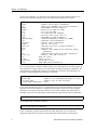
Command Modes..............................................................................................................4
User Mode...................................................................................................................4
Enable Mode...............................................................................................................4
Configure Mode .........................................................................................................5
Boot PROM Mode......................................................................................................5
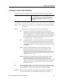
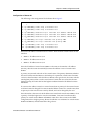
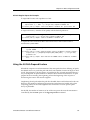
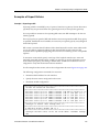
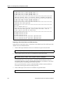
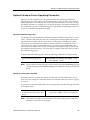
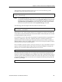
Getting Help with CLI Commands ................................................................................5
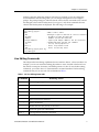
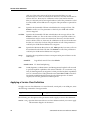
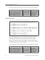
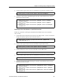
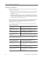
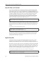
Line Editing Commands ..................................................................................................7
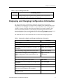
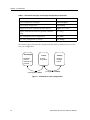
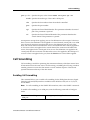
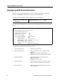
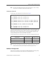
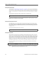
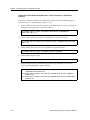
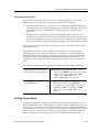
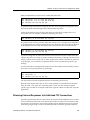
Displaying and Changing Configuration Information.......................................................9
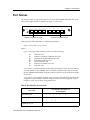
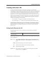
Port Names..................................................................................................................... .........11
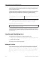
Chapter 2: Hot Swapping Line Cards and Control Modules................ 13
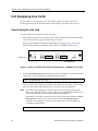
Hot Swapping Overview ......................................................................................................13
Hot Swapping Line Cards ....................................................................................................14
Deactivating the Line Card............................................................................................14
Removing the Line Card................................................................................................15
Installing a New Line Card ...........................................................................................15
Hot Swapping One Type of Line Card With Another...............................................15
Hot Swapping a Secondary Control Module.....................................................................16
Deactivating the Control Module .................................................................................16
Removing the Control Module .....................................................................................17
Installing a Control Module ..........................................................................................17
Hot Swapping a Switching Fabric Module (SSR 8600 only)............................................18
Removing the Switching Fabric Module .....................................................................19
Installing a Switching Fabric Module ..........................................................................19
Chapter 3: Bridging Configuration Guide ............................................. 21
Bridging Overview.................................................................................................................21
Spanning Tree (IEEE 802.1d) .........................................................................................21
Bridging Modes (Flow-Based and Address-Based) ...................................................22
VLAN Overview ....................................................................................................................22
Port-based VLANs...................................................................................................23
SmartSwitch Router User Reference Manual
xiii
Contents
MAC-address-based VLANs................................................................................. 23
Protocol-based VLANs........................................................................................... 23
Subnet-based VLANs ............................................................................................. 23
Multicast-based VLANs......................................................................................... 24
Policy-based VLANs .............................................................................................. 24
SSR VLAN Support........................................................................................................ 24
VLANs and the SSR................................................................................................ 24
Ports, VLANs, and L3 Interfaces .......................................................................... 25
Access Ports and Trunk Ports (802.1Q support)................................................. 25
Explicit and Implicit VLANs................................................................................. 26
Configuring SSR Bridging Functions ................................................................................. 26
Configuring Address-based or Flow-based Bridging............................................... 26
Configuring Spanning Tree .......................................................................................... 28
Adjusting Spanning-Tree Parameters ......................................................................... 28
Setting the Bridge Priority ..................................................................................... 29
Setting a Port Priority ............................................................................................. 29
Assigning Port Costs .............................................................................................. 29
Adjusting Bridge Protocol Data Unit (BPDU) Intervals.................................... 30
Adjusting the Interval between Hello Times............................................... 30
Defining the Forward Delay Interval............................................................ 30
Defining the Maximum Age .......................................................................... 30
Configuring a Port- or Protocol-Based VLAN ........................................................... 31
Creating a Port or Protocol Based VLAN............................................................ 31
Adding Ports to a VLAN ....................................................................................... 31
Configuring VLAN Trunk Ports .................................................................................. 31
Configuring VLANs for Bridging................................................................................ 32
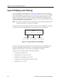
Configuring Layer-2 Filters .......................................................................................... 32
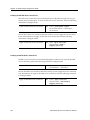
Monitoring Bridging ............................................................................................................ . 33
Configuration Examples....................................................................................................... 33
Creating an IP or IPX VLAN ........................................................................................ 33
Creating a non-IP/non-IPX VLAN.............................................................................. 34
Chapter 4: SmartTRUNK Configuration Guide ...................................... 35
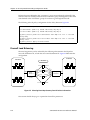
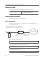
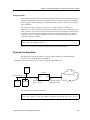
Overview ................................................................................................................................ 35
Configuring SmartTRUNKs ................................................................................................ 36
Creating a SmartTRUNK .............................................................................................. 36
Add Physical Ports to the SmartTRUNK.................................................................... 36
Specify Traffic Distribution Policy (Optional) ........................................................... 37
Monitoring SmartTRUNKs .................................................................................................. 37
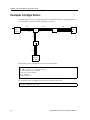
Example Configurations....................................................................................................... 38
Chapter 5: ATM Configuration Guide.................................................... 41
ATM Overview ...................................................................................................................... 41
Virtual Channels.................................................................................................................... 41
Creating a Virtual Channel ........................................................................................... 42
Service Class Definition........................................................................................................ 42
Creating a Service Class Definition ............................................................................. 43
Applying a Service Class Definition............................................................................ 44
Cell Scrambling...................................................................................................................... 45
xiv
SmartSwitch Router User Reference Manual
Contents
Enabling Cell Scrambling ..............................................................................................45
Cell Mapping ..........................................................................................................................46
Selecting the Cell Mapping Format..............................................................................46
Creating a Non-Zero VPI ......................................................................................................47
Setting the Bit Allocation for VPI..................................................................................47
Displaying ATM Port Information ......................................................................................48
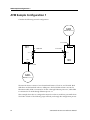
ATM Sample Configuration 1 ..............................................................................................52
Configuring an Interface on an Ethernet Port ............................................................53
Creating a Virtual Channel............................................................................................53
Defining an ATM Service Class ....................................................................................53
Applying an ATM Service Class...................................................................................54
Configuring an Interface on an ATM Port ..................................................................54
Configuring an IP Route ................................................................................................54
Chapter 6: Packet-over-SONET Configuration Guide ........................... 57
Overview .................................................................................................................................57
Configuring IP Interfaces for PoS Links ......................................................................58
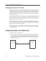
Configuring Packet-over-SONET Links .............................................................................58
Configuring Automatic Protection Switching ...................................................................59
Configuring Working and Protecting Ports................................................................60
Specifying Bit Error Rate Thresholds ..................................................................................61
Monitoring PoS Ports.............................................................................................................62
Example Configurations .......................................................................................................63
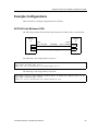
APS PoS Links Between SSRs........................................................................................63
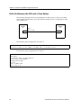
PoS Link Between the SSR and a Cisco Router...........................................................64
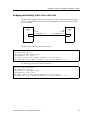
Bridging and Routing Traffic Over a PoS Link ..........................................................65
Chapter 7: DHCP Configuration Guide .................................................. 67
DHCP Overview ....................................................................................................................67
Configuring DHCP ................................................................................................................68
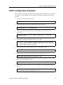
Configuring an IP Address Pool...................................................................................68
Configuring Client Parameters .....................................................................................68
Configuring a Static IP Address ...................................................................................69
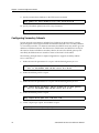
Grouping Scopes with a Common Interface...............................................................69
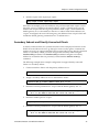
Configuring DHCP Server Parameters........................................................................70
Updating the Lease Database ...............................................................................................70
Monitoring the DHCP Server...............................................................................................70
DHCP Configuration Examples...........................................................................................71
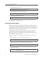
Configuring Secondary Subnets ...................................................................................72
Secondary Subnets and Directly-Connected Clients .................................................73
Interacting with Relay Agents.......................................................................................74
Chapter 8: IP Routing Configuration Guide .......................................... 77
IP Routing Protocols ..............................................................................................................77
Unicast Routing Protocols .............................................................................................77
Multicast Routing Protocols ..........................................................................................78
Configuring IP Interfaces and Parameters .........................................................................78
Configuring IP Interfaces to Ports ................................................................................79
Configuring IP Interfaces for a VLAN.........................................................................79
SmartSwitch Router User Reference Manual
xv
Contents
Specifying Ethernet Encapsulation Method............................................................... 79
Configuring Jumbo Frames .......................................................................................... 80
Configuring Address Resolution Protocol (ARP) ..................................................... 81
Configuring ARP Cache Entries ........................................................................... 81
Unresolved MAC Addresses for ARP Entries .................................................... 81
Configuring Proxy ARP ......................................................................................... 82
Configuring Reverse Address Resolution Protocol (RARP).................................... 82
Specifying IP Interfaces for RARP........................................................................ 83
Defining MAC-to-IP Address Mappings ............................................................ 83
Monitoring RARP ................................................................................................... 84
Configuring DNS Parameters ...................................................................................... 84
Configuring IP Services (ICMP)................................................................................... 84
Configuring IP Helper................................................................................................... 84
Configuring Direct Broadcast....................................................................................... 85
Configuring Denial of Service (DOS) .......................................................................... 86
Monitoring IP Parameters............................................................................................. 86
Configuring Router Discovery ............................................................................................ 87
Configuration Examples....................................................................................................... 90
Assigning IP/IPX Interfaces ......................................................................................... 90
Chapter 9: VRRP Configuration Guide ................................................... 91
VRRP Overview..................................................................................................................... 91
Configuring VRRP ................................................................................................................ 91
Basic VRRP Configuration ............................................................................................ 92
Configuration of Router R1 ................................................................................... 92
Configuration for Router R2.................................................................................. 93
Symmetrical Configuration .......................................................................................... 93
Configuration of Router R1 ................................................................................... 94
Configuration of Router R2 ................................................................................... 95
Multi-Backup Configuration ........................................................................................ 95
Configuration of Router R1 ................................................................................... 97
Configuration of Router R2 ................................................................................... 98
Configuration of Router R3 ................................................................................... 99
Additional Configuration ............................................................................................. 99
Setting the Backup Priority.................................................................................. 100
Setting the Advertisement Interval .................................................................... 100
Setting Pre-empt Mode ........................................................................................ 100
Setting an Authentication Key ............................................................................ 101
Monitoring VRRP ................................................................................................................ 101
ip-redundancy trace..................................................................................................... 101
ip-redundancy show.................................................................................................... 102
VRRP Configuration Notes................................................................................................ 103
Chapter 10: RIP Configuration Guide................................................... 105
RIP Overview....................................................................................................................... 105
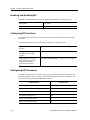
Configuring RIP................................................................................................................... 105
Enabling and Disabling RIP........................................................................................ 106
Configuring RIP Interfaces ......................................................................................... 106
Configuring RIP Parameters....................................................................................... 106
xvi
SmartSwitch Router User Reference Manual
Contents
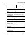
Configuring RIP Route Preference .............................................................................108
Configuring RIP Route Default-Metric......................................................................108
Monitoring RIP .....................................................................................................................108
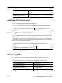
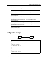
Configuration Example .......................................................................................................109
Chapter 11: OSPF Configuration Guide............................................... 111
OSPF Overview ....................................................................................................................111
OSPF Multipath.............................................................................................................112
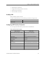
Configuring OSPF ................................................................................................................112
Enabling OSPF...............................................................................................................113
Configuring OSPF Interface Parameters ...................................................................113
Default Cost of an OSPF Interface ..............................................................................114
Configuring an OSPF Area ..........................................................................................115
Configuring OSPF Area Parameters ..........................................................................116
Creating Virtual Links..................................................................................................116
Configuring Autonomous System External (ASE) Link Advertisements ............117
Configuring OSPF for Different Types of Interfaces ...............................................117
Monitoring OSPF..................................................................................................................118
OSPF Configuration Examples...........................................................................................120
Exporting All Interface & Static Routes to OSPF .......................................121
Exporting All RIP, Interface & Static Routes to OSPF...............................121
Chapter 12: BGP Configuration Guide................................................. 125
BGP Overview ......................................................................................................................125
The SSR BGP Implementation.....................................................................................126
Basic BGP Tasks....................................................................................................................126
Setting the Autonomous System Number ................................................................127
Setting the Router ID ....................................................................................................127
Configuring a BGP Peer Group ..................................................................................127
Adding and Removing a BGP Peer ............................................................................129
Starting BGP...................................................................................................................129
Using AS-Path Regular Expressions ..........................................................................129
AS-Path Regular Expression Examples ..............................................................131
Using the AS Path Prepend Feature...........................................................................131
Notes on Using the AS Path Prepend Feature...................................................132
BGP Configuration Examples ............................................................................................132
BGP Peering Session Example ....................................................................................133
IBGP Configuration Example......................................................................................135
IBGP Routing Group Example.............................................................................136
IBGP Internal Group Example.............................................................................139
EBGP Multihop Configuration Example...................................................................142
Community Attribute Example ..................................................................................145
Notes on Using Communities..............................................................................152
Local Preference Examples ..........................................................................................152
Using the local-pref Option..................................................................................154
Using the set-pref Option .....................................................................................154
Multi-Exit Discriminator Attribute Example ............................................................155
EBGP Aggregation Example .......................................................................................156
Route Reflection Example............................................................................................157
SmartSwitch Router User Reference Manual
xvii
Contents
Notes on Using Route Reflection........................................................................ 160
Chapter 13: Routing Policy Configuration Guide................................ 161
Route Import and Export Policy Overview..................................................................... 161
Preference ...................................................................................................................... 162
Import Policies.............................................................................................................. 163
Import-Source........................................................................................................ 163
Route-Filter ............................................................................................................ 164
Export Policies .............................................................................................................. 164
Export-Destination................................................................................................ 164
Export-Source ........................................................................................................ 164
Route-Filter ............................................................................................................ 165
Specifying a Route Filter ............................................................................................. 165
Aggregates and Generates .......................................................................................... 166
Aggregate-Destination ......................................................................................... 167
Aggregate-Source.................................................................................................. 167
Route-Filter ............................................................................................................ 168
Authentication .............................................................................................................. 168
Authentication Methods ...................................................................................... 168
Authentication Keys and Key Management ..................................................... 169
Configuring Simple Routing Policies ............................................................................... 169
Redistributing Static Routes ....................................................................................... 170
Redistributing Directly Attached Networks ............................................................ 170
Redistributing RIP into RIP ........................................................................................ 171
Redistributing RIP into OSPF..................................................................................... 171
Redistributing OSPF to RIP ........................................................................................ 171
Redistributing Aggregate Routes .............................................................................. 171
Simple Route Redistribution Examples .................................................................... 172
Example 1: Redistribution into RIP .................................................................... 172
Exporting a Given Static Route to All RIP Interfaces ............................... 173
Exporting All Static Routes to All RIP Interfaces...................................... 173
Exporting All Static Routes Except the Default Route to All RIP Interfaces
173
Example 2: Redistribution into OSPF................................................................. 173
Exporting All Interface & Static Routes to OSPF ...................................... 174
Exporting All RIP, Interface & Static Routes to OSPF.............................. 174
Configuring Advanced Routing Policies ......................................................................... 175
Export Policies .............................................................................................................. 175
Creating an Export Destination.................................................................................. 177
Creating an Export Source .......................................................................................... 177
Import Policies.............................................................................................................. 177
Creating an Import Source.......................................................................................... 178
Creating a Route Filter ................................................................................................ 178
Creating an Aggregate Route ..................................................................................... 179
Creating an Aggregate Destination ........................................................................... 180
Creating an Aggregate Source.................................................................................... 180
Examples of Import Policies ....................................................................................... 180
Example 1: Importing from RIP.......................................................................... 180
Importing a Selected Subset of Routes from One RIP Trusted Gateway ....
183
xviii
SmartSwitch Router User Reference Manual
Contents
Importing a Selected Subset of Routes from All RIP Peers Accessible Over
a Certain Interface ...................................................................................183
Example 2: Importing from OSPF .......................................................................184
Importing a Selected Subset of OSPF-ASE Routes ....................................186
Examples of Export Policies ........................................................................................187
Example 1: Exporting to RIP ................................................................................187
Exporting a Given Static Route to All RIP Interfaces ................................188
Exporting a Given Static Route to a Specific RIP Interface ......................189
Exporting All Static Routes Reachable Over a Given Interface to a Specific
RIP-Interface.............................................................................................190
Exporting Aggregate-Routes into RIP .........................................................191
Example 2: Exporting to OSPF.............................................................................192
Exporting All Interface & Static Routes to OSPF .......................................193
Exporting All RIP, Interface & Static Routes to OSPF...............................194
Chapter 14: Multicast Routing Configuration Guide ......................... 197
IP Multicast Overview.........................................................................................................197
IGMP Overview ............................................................................................................197
DVMRP Overview ........................................................................................................198
Configuring IGMP ...............................................................................................................199
Configuring IGMP on an IP Interface ........................................................................199
Configuring IGMP Query Interval .............................................................................199
Configuring IGMP Response Wait Time...................................................................199
Configuring Per-Interface Control of IGMP Membership......................................200
Configuring Static IGMP Groups ...............................................................................200
Configuring DVMRP ...........................................................................................................200
Starting and Stopping DVMRP...................................................................................201
Configuring DVMRP on an Interface ........................................................................201
Configuring DVMRP Parameters ...............................................................................201
Configuring the DVMRP Routing Metric .................................................................202
Configuring DVMRP TTL & Scope ............................................................................202
Configuring a DVMRP Tunnel ...................................................................................203
Monitoring IGMP & DVMRP.............................................................................................203
Configuration Examples .....................................................................................................204
Chapter 15: IP Policy-Based Forwarding Configuration Guide.......... 207
Overview ...............................................................................................................................207
Configuring IP Policies........................................................................................................208
Defining an ACL Profile ..............................................................................................208
Associating the Profile with an IP Policy ..................................................................208
Creating Multi-Statement IP Policies..................................................................209
Setting the IP Policy Action..................................................................................209
Setting Load Distribution for Next-Hop Gateways..........................................210
Applying an IP Policy to an Interface ........................................................................210
Applying an IP Policy to Locally Generated Packets .......................................210
IP Policy Configuration Examples.....................................................................................211
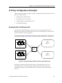
Routing Traffic to Different ISPs.................................................................................211
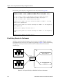
Prioritizing Service to Customers...............................................................................212
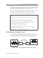
Authenticating Users through a Firewall..................................................................213
SmartSwitch Router User Reference Manual
xix
Contents
Firewall Load Balancing.............................................................................................. 214
Monitoring IP Policies ........................................................................................................ 215
Chapter 16: Network Address Translation Configuration Guide ...... 219
Overview .............................................................................................................................. 219
Configuring NAT ................................................................................................................ 220
Setting Inside and Outside Interfaces ....................................................................... 220
Setting NAT Rules........................................................................................................ 221
Static........................................................................................................................ 221
Dynamic ................................................................................................................. 221
Forcing Flows through NAT.............................................................................................. 221
Managing Dynamic Bindings............................................................................................ 222
NAT and DNS...................................................................................................................... 222
NAT and ICMP Packets ..................................................................................................... 223
NAT and FTP ....................................................................................................................... 223
Monitoring NAT.................................................................................................................. 224
Configuration Examples..................................................................................................... 224
Static Configuration ..................................................................................................... 224
Using Static NAT .................................................................................................. 225
Dynamic Configuration............................................................................................... 225
Using Dynamic NAT ............................................................................................ 226
Dynamic NAT with IP Overload (PAT) Configuration ......................................... 227
Using Dynamic NAT with IP Overload ............................................................ 227
Dynamic NAT with DNS ............................................................................................ 228
Using Dynamic NAT with DNS ......................................................................... 229
Dynamic NAT with Outside Interface Redundancy .............................................. 229
Using Dynamic NAT with Matching Interface Redundancy......................... 230
Chapter 17: Web Hosting Configuration Guide.................................. 231
Overview .............................................................................................................................. 231
Load Balancing .................................................................................................................... 232
Configuring Load Balancing ...................................................................................... 232
Creating the Server Group................................................................................... 232
Adding Servers to the Load Balancing Group.................................................. 232
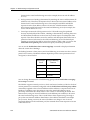
Session Persistence....................................................................................................... 233
Optional Group or Server Operating Parameters ................................................... 235
Specifying Load Balancing Policy ...................................................................... 235
Specifying a Connection Threshold ................................................................... 235
Verifying Servers and Applications ................................................................... 236
Verifying Extended Content................................................................................ 237
Setting Server Status .................................................................................................... 237
Load Balancing and FTP ............................................................................................. 238
Allowing Access to Load Balancing Servers ............................................................ 238
Setting Timeouts for Load Balancing Mappings ..................................................... 238
Displaying Load Balancing Information .................................................................. 239
Configuration Examples ............................................................................................. 239
Web Hosting with One Virtual Group and Multiple Destination Servers... 240
Web Hosting with Multiple Virtual Groups and Multiple Destination Servers
241
xx
SmartSwitch Router User Reference Manual
Contents
Virtual IP Address Ranges ...................................................................................242
Session and Netmask Persistence........................................................................243
Web Caching.........................................................................................................................244
Configuring Web Caching ...........................................................................................244
Creating the Cache Group....................................................................................244
Specifying the Client(s) for the Cache Group (Optional).................................245
Redirecting HTTP Traffic on an Interface ..........................................................245
Configuration Example ................................................................................................246
Other Configurations ...................................................................................................246
Bypassing Cache Servers ......................................................................................246
Proxy Server Redundancy ....................................................................................247
Distributing Frequently-Accessed Sites Across Cache Servers.......................247
Monitoring Web-Caching ............................................................................................247
Chapter 18: IPX Routing Configuration Guide.................................... 249
IPX Routing Overview ........................................................................................................249
RIP (Routing Information Protocol) ...........................................................................249
SAP (Service Advertising Protocol) ...........................................................................250
Configuring IPX RIP & SAP ...............................................................................................251
IPX RIP............................................................................................................................251
IPX SAP ..........................................................................................................................251
Creating IPX Interfaces ................................................................................................251
IPX Addresses................................................................................................................251
Configuring IPX Interfaces and Parameters.....................................................................252
Configuring IPX Addresses to Ports ..........................................................................252
Configuring Secondary Addresses on an IPX Interface..........................................252
Configuring IPX Interfaces for a VLAN ....................................................................252
Specifying IPX Encapsulation Method ......................................................................253
Configuring IPX Routing ....................................................................................................253
Enabling IPX RIP...........................................................................................................253
Enabling SAP .................................................................................................................253
Configuring Static Routes............................................................................................254
Configuring Static SAP Table Entries ........................................................................254
Controlling Access to IPX Networks..........................................................................254
Creating an IPX Access Control List ...................................................................254
Creating an IPX Type 20 Access Control List ....................................................255
Creating an IPX SAP Access Control List ..........................................................255
Creating an IPX GNS Access Control List..........................................................256
Creating an IPX RIP Access Control List............................................................256
Monitoring an IPX Network...............................................................................................257
Configuration Examples .....................................................................................................257
Chapter 19: Access Control List Configuration Guide ........................ 259
ACL Basics ............................................................................................................................260
Defining Selection Criteria in ACL Rules..................................................................260
How ACL Rules are Evaluated...................................................................................262
Implicit Deny Rule........................................................................................................262
Allowing External Responses to Established TCP Connections ............................263
Creating and Modifying ACLs...........................................................................................264
SmartSwitch Router User Reference Manual
xxi
Contents
Editing ACLs Offline ................................................................................................... 264
Maintaining ACLs Using the ACL Editor ................................................................ 265
Using ACLs .......................................................................................................................... 266
Applying ACLs to Interfaces...................................................................................... 266
Applying ACLs to Services......................................................................................... 267
Applying ACLs to Layer-4 Bridging Ports............................................................... 267
Using ACLs as Profiles ................................................................................................ 268
Using Profile ACLs with the IP Policy Facility................................................. 269
Using Profile ACLs with the Traffic Rate Limiting Facility............................ 269
Using Profile ACLs with Dynamic NAT ........................................................... 270
Using Profile ACLs with the Port Mirroring Facility ...................................... 271
Using Profile ACLs with the Web Caching Facility......................................... 271
Redirecting HTTP Traffic to Cache Servers ............................................... 272
Preventing Web Objects From Being Cached............................................ 272
Enabling ACL Logging....................................................................................................... 273
Monitoring ACLs................................................................................................................. 274
Chapter 20: Security Configuration Guide .......................................... 275
Security Overview............................................................................................................... 275
Configuring SSR Access Security...................................................................................... 276
Configuring RADIUS .................................................................................................. 276
Monitoring RADIUS............................................................................................. 277
Configuring TACACS ................................................................................................. 277
Monitoring TACACS............................................................................................ 277
Configuring TACACS Plus......................................................................................... 278
Monitoring TACACS Plus ................................................................................... 279
Configuring Passwords............................................................................................... 279
Layer-2 Security Filters....................................................................................................... 279
Configuring Layer-2 Address Filters ........................................................................ 280
Configuring Layer-2 Port-to-Address Lock Filters ................................................. 281
Configuring Layer-2 Static Entry Filters................................................................... 281
Configuring Layer-2 Secure Port Filters ................................................................... 282
Monitoring Layer-2 Security Filters .......................................................................... 283
Layer-2 Filter Examples............................................................................................... 283
Example 1: Address Filters .................................................................................. 283
Static Entries Example................................................................................... 284
Port-to-Address Lock Examples .................................................................. 284
Example 2 : Secure Ports ...................................................................................... 285
Layer-3 Access Control Lists (ACLs)................................................................................ 285
Layer-4 Bridging and Filtering .......................................................................................... 286
Creating a Port-Based VLAN for Layer-4 Bridging ................................................ 287
Placing the Ports on the Same VLAN ....................................................................... 287
Enabling Layer-4 Bridging on the VLAN ................................................................. 287
Creating ACLs to Specify Selection Criteria for Layer-4 Bridging ....................... 287
Applying a Layer-4 Bridging ACL to a Port ............................................................ 288
Notes .............................................................................................................................. 288
Chapter 21: QoS Configuration Guide................................................. 291
QoS & Layer-2/Layer-3/Layer-4 Flow Overview.......................................................... 291
xxii
SmartSwitch Router User Reference Manual
Contents
Layer-2 and Layer-3 & Layer-4 Flow Specification..................................................292
Precedence for Layer-3 Flows .....................................................................................293
SSR Queuing Policies....................................................................................................293
Traffic Prioritization for Layer-2 Flows ............................................................................293
Configuring Layer-2 QoS.............................................................................................294
802.1p Priority Mapping ..............................................................................................294
Creating and Applying a New Priority Map.....................................................295
Removing or Disabling Per-Port Priority Map..................................................295
Displaying Priority Map Information.................................................................296
Traffic Prioritization for Layer-3 & Layer-4 Flows..........................................................296
Configuring IP QoS Policies ........................................................................................296
Setting an IP QoS Policy .......................................................................................297
Specifying Precedence for an IP QoS Policy ......................................................297
Configuring IPX QoS Policies .....................................................................................297
Setting an IPX QoS Policy.....................................................................................297
Specifying Precedence for an IPX QoS Policy ...................................................298
Configuring SSR Queueing Policy.....................................................................................298
Allocating Bandwidth for a Weighted-Fair Queuing Policy ..................................298
Weighted Random Early Detection (WRED) ...................................................................299
ToS Rewrite ...........................................................................................................................299
Configuring ToS Rewrite for IP Packets....................................................................300
Monitoring QoS ....................................................................................................................302
Limiting Traffic Rate............................................................................................................303
Rate Limiting Modes ....................................................................................................303
Per-Flow Rate Limiting ................................................................................................304
Port Rate Limiting.........................................................................................................304
Aggregate Rate Limiting..............................................................................................305
Example Configurations ..............................................................................................306
Per-Flow Rate Limiting.........................................................................................306
Aggregate Rate Limiting.......................................................................................307
Displaying Rate Limit Information ............................................................................308
Chapter 22: Performance Monitoring Guide ...................................... 309
Performance Monitoring Overview ..................................................................................309
Configuring the SSR for Port Mirroring ...........................................................................311
Monitoring Broadcast Traffic .............................................................................................311
Chapter 23: RMON Configuration Guide ............................................ 313
RMON Overview .................................................................................................................313
Configuring and Enabling RMON ....................................................................................314
Example of RMON Configuration Commands ........................................................314
RMON Groups ..............................................................................................................315
Lite RMON Groups ...............................................................................................315
Standard RMON Groups......................................................................................316
Professional RMON Groups ................................................................................316
Control Tables ...............................................................................................................317
Using RMON ........................................................................................................................318
Configuring RMON Groups...............................................................................................319
SmartSwitch Router User Reference Manual
xxiii
Contents
Configuration Examples ............................................................................................. 321
Displaying RMON Information ........................................................................................ 322
RMON CLI Filters ........................................................................................................ 323
Creating RMON CLI Filters................................................................................. 325
Using RMON CLI Filters ..................................................................................... 325
Troubleshooting RMON..................................................................................................... 325
Allocating Memory to RMON........................................................................................... 327
Chapter 24: LFAP Configuration Guide................................................ 329
Overview .............................................................................................................................. 329
Cabletron’s Traffic Accounting Services.......................................................................... 330
Configuring the LFAP Agent on the SSR......................................................................... 330
Monitoring the LFAP Agent on the SSR .......................................................................... 332
Chapter 25: WAN Configuration Guide ............................................... 333
WAN Overview................................................................................................................... 333
High-Speed Serial Interface (HSSI) and Standard Serial Interfaces ..................... 333
Configuring WAN Interfaces ..................................................................................... 334
Primary and Secondary Addresses ........................................................................... 334
Static, Mapped, and Dynamic Peer IP/IPX Addresses .......................................... 334
Static Addresses .................................................................................................... 334
Mapped Addresses ............................................................................................... 335
Dynamic Addresses.............................................................................................. 335
Forcing Bridged Encapsulation.................................................................................. 336
Packet Compression..................................................................................................... 336
Average Packet Size.............................................................................................. 337
Nature of the Data ................................................................................................ 337
Link Integrity ......................................................................................................... 337
Latency Requirements.......................................................................................... 337
Example Configurations ...................................................................................... 337
Packet Encryption ........................................................................................................ 338
WAN Quality of Service.............................................................................................. 338
Source Filtering and ACLs................................................................................... 339
Weighted-Fair Queueing ..................................................................................... 339
Congestion Management ..................................................................................... 339
Random Early Discard (RED) ...................................................................... 339
Adaptive Shaping .......................................................................................... 340
Frame Relay Overview ....................................................................................................... 340
Virtual Circuits ............................................................................................................. 340
Permanent Virtual Circuits (PVCs) .................................................................... 341
Configuring Frame Relay Interfaces for the SSR ............................................................ 341
Defining the Type and Location of a Frame Relay and VC Interface................... 341
Setting up a Frame Relay Service Profile.................................................................. 342
Applying a Service Profile to an Active Frame Relay WAN Port......................... 342
Monitoring Frame Relay WAN Ports............................................................................... 343
Frame Relay Port Configuration ....................................................................................... 343
Point-to-Point Protocol (PPP) Overview.......................................................................... 345
Use of LCP Magic Numbers ....................................................................................... 345
Configuring PPP Interfaces................................................................................................ 345
xxiv
SmartSwitch Router User Reference Manual
Contents
Defining the Type and Location of a PPP Interface .................................................346
Setting up a PPP Service Profile..................................................................................346
Applying a Service Profile to an Active PPP Port....................................................347
Configuring Multilink PPP Bundles ..........................................................................347
Compression on MLP Bundles or Links.............................................................347
Monitoring PPP WAN Ports...............................................................................................348
PPP Port Configuration .......................................................................................................348
WAN Configuration Examples ..........................................................................................350
Simple Configuration File............................................................................................350
Multi-Router WAN Configuration.............................................................................351
Router R1 Configuration File ...............................................................................352
Router R2 Configuration File ...............................................................................352
Router R3 Configuration File ...............................................................................353
Router R4 Configuration File ...............................................................................353
Router R5 Configuration File ...............................................................................354
Router R6 Configuration File ...............................................................................354
Appendix A: New Features Supported on Line Cards........................ 357
Introduction ..........................................................................................................................357
SSR 8000/8600 Line Cards ..................................................................................................357
Line Cards Available Prior to the 3.0 Firmware Release ........................................357
Line Cards Introduced at the 3.0 Firmware Release (-AA Revision) ....................358
Line Cards Introduced at the 3.1 Firmware Release (T-Series) ..............................359
SSR 2000 Line Cards ............................................................................................................361
New Features that Require Specific Line Cards ..............................................................362
Network Address Translation.....................................................................................362
Load Balancing (LSNAT).............................................................................................364
Layer 4 Bridging............................................................................................................365
Per-Protocol VLAN.......................................................................................................366
QoS Rate Limiting.........................................................................................................367
Per-Flow Rate Limiting.........................................................................................367
Aggregate Rate Limiting.......................................................................................367
Port Rate Limiting..................................................................................................367
ToS Rewrite....................................................................................................................368
Established Bit ACL......................................................................................................368
Multiple IPX Encapsulation.........................................................................................368
Weighted Random Early Detection (WRED)............................................................369
Jumbo Frames................................................................................................................369
Summary ...............................................................................................................................369
Identifying a Line Card .......................................................................................................370
Example 1:...............................................................................................................370
Example 2:...............................................................................................................371
Example 3:...............................................................................................................371
SmartSwitch Router User Reference Manual
xxv
Contents
xxvi
SmartSwitch Router User Reference Manual
About This Manual
This manual provides information and procedures for configuring the SmartSwitch
Router (SSR) software. If you have not yet installed the SSR, use the instructions in the
SmartSwitch Router Getting Started Guide to install the chassis and perform basic setup
tasks, then return to this manual for more detailed configuration information.
Related Documentation
The SmartSwitch Router documentation set includes the following items. Refer to these
other documents to learn more about your product.
For Information About
See
Installing and setting up the SSR
SmartSwitch Router Getting Started Guide
Managing the SSR using Cabletron’s
element management application
CoreWatch User’s Manual and the
CoreWatch online help
Syntax for CLI commands
SmartSwitch Router Command Line
Interface Reference Manual
Document Conventions
Commands shown in this manual use the following conventions:
Convention
Description
boldface
Indicates commands and keywords that you enter as shown.
<italics>
Indicates arguments for which you supply values.
SmartSwitch Router User Reference Manual
1
Preface
2
Convention
Description
[x] or
[<italics>] or
[x <italics>]
Keywords and arguments within a set of square brackets are
optional.
x|y|z|<italics> or
[x|y|z|<italics>]
Keywords or arguments separated by vertical bars indicate a
choice. Select one keyword or argument.
{x|y|z|<italics>}
Braces group required choices. Select one keyword or
argument.
SmartSwitch Router User Reference Manual
Chapter 1
Introduction
This chapter provides information that you need to know before configuring the
SmartSwitch Router (SSR). If you have not yet installed the SSR, use the instructions in the
SmartSwitch Router Getting Started Guide to install the chassis and perform basic setup
tasks, then return to this manual for more detailed configuration information.
Configuration Files
The SmartSwitch Router Getting Started Guide introduced the following configuration files
used by the SSR:
•
Startup – The configuration file that the SSR uses to configure itself when the system
is powered on. The Startup configuration remains even when the system is rebooted.
•
Active – The commands from the Startup configuration file and any configuration
commands that you have made active from the scratchpad. The active configuration
remains in effect until you power down or reboot the system.
•
Scratchpad – The configuration commands you have entered during a CLI session.
These commands are temporary and do not become active until you explicitly make
them part of the active configuration.
Note:
Because some commands depend on other commands for successful execution,
the SSR scratchpad simplifies system configuration by allowing you to enter
configuration commands in any order, even when dependencies exist. When you
activate the commands in the scratchpad, the SSR sorts out the dependencies and
executes the command in the proper sequence.
Entering commands and saving configuration files are discussed in more detail in the
following section.
SmartSwitch Router User Reference Manual
3
Chapter 1: Introduction
Using the Command Line Interface
Note:
The SSR provides both a graphical user interface (CoreWatch) and a command
line interface (CLI) to configure and manage the SSR. In this manual, example
configurations show how to use the CLI commands to configure the SSR. Using
CoreWatch is described in the CoreWatch User’s Manual.
The CLI allows you to enter and execute commands from the SSR Console or from Telnet
sessions. Up to four simultaneous Telnet sessions are allowed. CLI commands are
grouped by subsystems. For example, the set of commands that let you configure and
display IP routing table information all start with ip. Within the set of ip commands are
commands such as set, show, start, stop, configure, etc. The complete set of commands
for each subsystem is described in the SmartSwitch Router Command Line Interface Reference
Manual.
Command Modes
The CLI provides access to four different command modes. Each command mode
provides a group of related commands. This section describes how to access and list the
commands available in each command mode and explains the primary uses for each
command mode.
User Mode
After you log in to the SSR, you are automatically in User mode. The User commands
available are a subset of those available in Enable mode. In general, the User commands
allow you to display basic information and use basic utilities such as ping.
The User mode command prompt consists of the SSR name followed by the angle bracket
(>), as shown below:
ssr>
The default name is SSR unless it has been changed during initial configuration. Refer to
the SmartSwitch Router Getting Started Guide for the procedures for changing the system
name.
Enable Mode
Enable mode provides more facilities than User mode. You can display critical features
within Enable mode including router configuration, access control lists, and SNMP
statistics. To enter Enable mode from the User mode, enter the command enable (or en),
then supply the password when prompted.
4
SmartSwitch Router User Reference Manual
Chapter 1: Introduction
The Enable mode command prompt consists of the SSR name followed by the pound
sign(#):
ssr#
To exit Enable mode and return to User mode, either type exit and press Return, or press
Ctrl+Z.
Configure Mode
Configure mode provides the capabilities to configure all features and functions on the
SSR. These include router configuration, access control lists and spanning tree. To enter
Configure mode, enter the command config from Enable mode.
Note:
As mentioned previously, up to four Telnet sessions can be run simultaneously on
the SSR. All four sessions can be in Configure mode at the same time, so you
should consider limiting access to the SSR to authorized users.
The Configure mode command prompt consists of the SSR name followed by (config) and
a pound sign (#):
ssr(config)#
To exit Configure mode and return to Enable mode, either type exit and press Return, or
press Ctrl+Z.
Boot PROM Mode
If your SSR does not find a valid system image on the external PCMCIA flash, the system
might enter programmable read-only memory (PROM) mode. You should then reboot the
SSR (enter the command reboot at the boot PROM prompt) to restart the system. If the
system fails to reboot successfully, please call Cabletron Systems Technical Support to
resolve the problem.
For information on how to upgrade the boot PROM software and boot using the
upgraded image, see the SmartSwitch Router Getting Started Guide.
Getting Help with CLI Commands
Interactive help is available from CLI by entering the question mark (?) character at any
time. The help is context-sensitive; the help provided is based on where in the command
SmartSwitch Router User Reference Manual
5
Chapter 1: Introduction
you are. For example, if you are at the User mode prompt, enter a question mark (?) as
shown in the following example to list the commands available in User mode:
ssr> ?
aging
cli
dvmrp
enable
exit
file
help
igmp
ip-redundancy
ipx
l2-tables
logout
multicast
ping
pvst
sfs
statistics
stp
telnet
traceroute
vlan
-
-
Show L2 and L3 Aging information
Modify the command line interface behavior
Show DVMRP related parameters
Enable privileged user mode
Exit current mode
File manipulation commands
Describe online help facility
Show IGMP related parameters
Show IP Redundancy information (VRRP)
Show IPX related parameters
Show L2 Tables information
Log off the system
Configure Multicast related parameters
Ping utility
Show Per Vlan Spanning Tree Protocol (PVST)
parameters
- Show SecureFast Switching (SFS) parameters
- Show or clear SSR statistics
Show STP status
Telnet utility
Traceroute utility
Show VLAN-related parameters
You can also type the ? character while entering in a command line to see a description of
the parameters or options that you can enter. Once the help information is displayed, the
command line is redisplayed as before but without the ? character. The following is an
example of invoking help while entering a command:
ssr(config)# load-balance
group-name
vip-range-name
ssr(config)# load-balance
create ?
- Name of this Load Balanced group of servers
- Name of this Virtual IP range
create
If you enter enough characters of a command keyword to uniquely identify it and press
the space bar, the CLI attempts to complete the command. If you do not enter enough
characters or you enter the wrong characters, CLI cannot complete the command. For
example, if you enter the following in Enable mode and press the spacebar as indicated:
ssr# system show e[space]
CLI completes the command as follows:
ssr# system show environmental
If you are entering several commands for the same subsystem, you can enter the
subsystem name from CLI. Then, execute individual commands for the subsystem
6
SmartSwitch Router User Reference Manual
Chapter 1: Introduction
without typing the subsystem name in each time. For example, if you are configuring
several entries for the IP routing table, you can simply enter ip at the CLI Configure
prompt. The prompt changes to indicate that the context for the commands to be entered
has changed to that of the IP subsystem. If you type a ?, only those commands that are
valid for the IP subsystem are displayed. The following is an example:
ssr(config)# ip
ssr(config)(ip)# ?
add
- Add a static route
dos
- Configure specific denial of service features
disable
- Disable certain IP function
enable
- Enable certain IP function
helper-address
- Specify IP helper address for an interface
l3-hash
- Change IP hash variant for channel
set
- Set ip stack properties
Ctrl-z
- Exits to previous level
top
- Exits to the top level
ssr(config)(ip)# [Ctrl-Z]
ssr(config)#
Line Editing Commands
The SSR provides line editing capabilities that are similar to Emacs, a Unix text editor. For
example, you can use certain line editing keystrokes to move forward or backward on a
line, delete or transpose characters, and delete portions of a line. To use the line editing
commands, you need to have a VT-100 terminal or terminal emulator. The line editing
commands that you can use with CLI are detailed in Table 1.
Table 1. CLI Line Editing Commands
Command
Resulting Action
Ctrl-a
Move to beginning of line
Ctrl-b
Move back one character
Ctrl-c
Abort current line
Ctrl-d
Delete character under cursor
Ctrl-e
Move to end of line
Ctrl-f
Move forward one character
Ctrl-g
Abort current line
Ctrl-h
Delete character just priority to the cursor
Ctrl-i
Insert one space (tab substitution)
Ctrl-j
Carriage return (executes command)
SmartSwitch Router User Reference Manual
7
Chapter 1: Introduction
Table 1. CLI Line Editing Commands
Command
8
Resulting Action
Ctrl-k
Kill line from cursor to end of line
Ctrl-l
Refresh current line
Ctrl-m
Carriage return (executes command)
Ctrl-n
Next command from history buffer
Ctrl-o
None
Ctrl-p
Previous command from history buffer
Ctrl-q
None
Ctrl-r
Refresh current line
Ctrl-s
None
Ctrl-t
Transpose character under cursor with the character just prior to the
cursor
Ctrl-u
Delete line from the beginning of line to cursor
Ctrl-v
None
Ctrl-w
None
Ctrl-x
Move forward one word
Ctrl-y
Paste back what was deleted by the previous Ctrl-k or Ctrl-w command.
Text is pasted back at the cursor location
Ctrl-z
If inside a subsystem, it exits back to the top level. If in Enable mode, it
exits back to User mode. If in Configure mode, it exits back to Enable
mode.
ESC-b
Move backward one word
ESC-d
Kill word from cursor’s current location until the first white space.
ESC-f
Move forward one word
ESCBackSpace
Delete backwards from cursor to the previous space (essentially a deleteword-backward command)
SPACE
Attempts to complete command keyword. If word is not expected to be a
keyword, the space character is inserted.
!*
Show all commands currently stored in the history buffer.
!#
Recall a specific history command. ‘#’ is the number of the history
command to be recalled as shown via the ‘!*’ command.
SmartSwitch Router User Reference Manual
Chapter 1: Introduction
Table 1. CLI Line Editing Commands
Command
“<string>”
Resulting Action
Opaque strings may be specified using double quotes. This prevents
interpretation of otherwise special CLI characters.
Displaying and Changing Configuration Information
The SSR provides many commands for displaying and changing configuration
information. For example, the CLI allows for the “disabling” of a command in the active
configuration. Use the negate command on a specific line of the active configuration to
“disable” a feature or function which has been enabled. For example, Spanning Tree
Protocol is disabled by default. If, after enabling the Spanning Tree Protocol on the
SmartSwitch Router, you want to disable STP, you must specify the negate command with
the line number in the active configuration that contains the stp enable command.
The table below shows some commands that are useful when configuring the SSR.
Table 2. Commands to Display and Change Configuration Information
Task
Command
Enable Mode:
Show active configuration of the system.
system show active
Show the non-activated configuration changes in the
scratchpad.
system show scratchpad
Show the startup configuration for the next reboot.
system show startup
Copy between scratchpad, active configuration,
startup configuration, TFTP server, RCP server, or
URL.
copy <source> to
<destination>
Configure Mode:
Show active configuration of the system.
show active
Show the non-activated configuration changes in the
scratchpad.
show scratchpad
Show the startup configuration for the next reboot.
show startup
Show the running system configuration, followed by
the non-activated changes in the scratchpad.
show
Compare activated commands with the startup
configuration file.
diff <filename> | startup
SmartSwitch Router User Reference Manual
9
Chapter 1: Introduction
Table 2. Commands to Display and Change Configuration Information
Task
Command
Erase commands in scratchpad.
erase scratchpad
Erase startup configuration.
erase startup
Negate one or more commands by line numbers.
negate <line number>
Negate commands that match a specified command
string.
no <string>
Save scratchpad to active configuration.
save active
Save active configuration to startup.
save startup
The following figure illustrates the configuration files and the commands you can use to
save your configuration:
Scratchpad
temporary
location;
contents lost
at reboot
Active
Startup
in effect
until reboot
remains
through
reboot
(config)# save active
(config)# save startup
Figure 1. Commands to Save Configurations
10
SmartSwitch Router User Reference Manual
Chapter 1: Introduction
Port Names
The term port refers to a physical connector on a line card installed in the SSR. The figure
below shows eight 10 Base-T/100 Base-TX ports on a line card.
SSR-HTX12-08
1
10/100BASE-TX
2
3
4
5
6
7
8
Offline
Hot
Swap
Online
10 BASE-T/100 BASE-TX ports
10 BASE-T/100 BASE-TX ports
Each port in the SSR is referred to in the following manner:
<type>.<slot-number>.<port-number>
where:
<type> is the type of line card and can be one of the following:
at
et
gi
hs
se
so
at
ATM line card
10 Base-X/100 Base-X Ethernet line card
1000 Base-X Gigabit Ethernet line card
Dual HSSI WAN line card
Serial WAN line card
Packet-over-SONET line card
ATM line card
<slot-number> is determined by the SSR model and the physical slot in which the line
card is installed. On the SSR 2000, the slot number is printed on the side of each slot.
On the SSR 8000 and SSR 8600, a legend printed on the fan tray shows the slot number
of each slot.
<port-number> is the number assigned to the connector on the line card. The range and
assignment of port numbers varies by the type of line card. The assignment of port
numbers by line card is shown in the table below:
Table 3. Port Numbers for Line Cards
Port Number Arrangement
(Left to Right)
Line Card
10/100 Base TX
1
2
100 Base FX
3
1
4
2
1000 Base SX/LX
1
2
SmartSwitch Router User Reference Manual
3
4
7
5
5
6
7
8
8
6
11
Chapter 1: Introduction
Table 3. Port Numbers for Line Cards
Port Number Arrangement
(Left to Right)
Line Card
1000 Base LLX
1
Quad Serial WAN
1,2
HSSI WAN
1
2
SONET (OC-3c)
1
2
SONET (OC-12c)
1
2
ATM (OC-3)
1
2
16-slot 100 Base TX
5
1
6
2
3,4
3
4
7
3
8
4
13
9
14 15 16
10
11 12
For example, the port name et.2.8 refers to the port on the Ethernet line card located in slot
2, connector 8, while the port name gi.3.2 refers to the port on the Gigabit Ethernet line
card located in slot 3, connector 2.
There are a few shortcut notations you can use to reference a range of port numbers. For
example:
12
•
et.(1-3).(1-8) references all the following ports: et.1.1 through et.1.8, et.2.1 through
et.2.8, and et.3.1 through et.3.8.
•
et.(1,3).(1-8) references the following ports: et.1.1 through et.1.8, and et.3.1 through
et.3.8
•
et.(1-3).(1,8) references the following ports: et.1.1, et.1.8, et.2.1, et.2.8, et.3.1, et.3.8
SmartSwitch Router User Reference Manual
Chapter 2
Hot Swapping
Line Cards and
Control Modules
Hot Swapping Overview
This chapter describes the hot swapping functionality of the SSR. Hot swapping is the
ability to replace a line card or Control Module while the SSR is operating. Hot swapping
allows you to remove or install line cards without switching off or rebooting the SSR.
Swapped-in line cards are recognized by the SSR and begin functioning immediately after
they are installed.
On the SSR 8000 and SSR 8600, you can hot swap line cards and secondary control
modules. On the SSR 8600, you can also hot swap the secondary switching fabric module.
This chapter provides instructions for the following tasks:
•
Hot swapping line cards
•
Hot swapping secondary Control Modules
•
Hot swapping the secondary Switching Fabric Module (SSR 8600 only)
SmartSwitch Router User Reference Manual
13
Chapter 2: Hot Swapping Line Cards and Control Modules
Hot Swapping Line Cards
The procedure for hot swapping a line card consists of deactivating the line card,
removing it from its slot in the SSR chassis, and installing a new line card in the slot.
Deactivating the Line Card
To deactivate the line card, do one of the following:
•
Press the Hot Swap button on the line card. The Hot Swap button is recessed in the line
card's front panel. Use a pen or similar object to reach it.
When you press the Hot Swap button, the Offline LED lights. Figure 2 shows the
location of the Offline LED and Hot Swap button on a 1000Base-SX line card.
SSR-GSX11-02
Offline
Tx Link
1000BASE-SX
1
Tx Link
2
Hot
Offline LED
Online
Rx AN
Rx AN
Swap
Hot Swap Button
Figure 2. Location of Offline LED and Hot Swap Button on a 1000Base-SX Line Card
•
Use the system hotswap out command in the CLI. For example, to deactivate the line
card in slot 7, enter the following command in Enable mode:
ssr# system hotswap out slot 7
After you enter this command, the Offline LED on the line card lights, and messages
appear on the console indicating the ports on the line card are inoperative.
Note:
If you have deactivated a line card and want to activate it again, simply pull it
from its slot and push it back in again. (Make sure the Offline LED is lit before you
pull out the line card.) The line card is activated automatically.
Alternately, if you have not removed a line card you deactivated with the system
hotswap out command, you can reactivate it with the system hotswap in
command. For example, to reactivate a line card in slot 7, enter the following
command in Enable mode:
ssr# system hotswap in slot 7
14
SmartSwitch Router User Reference Manual
Chapter 2: Hot Swapping Line Cards and Control Modules
Removing the Line Card
To remove a line card from the SSR:
1.
Make sure the Offline LED on the line card is lit.
Warning: Do not remove the line card unless the Offline LED is lit. Doing so can cause the
SSR to crash.
2.
Loosen the captive screws on each side of the line card.
3.
Carefully remove the line card from its slot in the SSR chassis.
Installing a New Line Card
To install a new line card:
1.
Slide the line card all the way into the slot, firmly but gently pressing the line card
fully in place to ensure that the pins on the back of the line card are completely seated
in the backplane.
Note:
2.
Make sure the circuit card (and not the metal plate) is between the card
guides. Check both the upper and lower tracks.
Tighten the captive screws on each side of the line card to secure it to the chassis.
Once the line card is installed, the SSR recognizes and activates it. The Online LED
button lights.
Hot Swapping One Type of Line Card With Another
You can hot swap one type of line card with another type. For example, you can replace a
10/100Base-TX line card with a 1000Base-SX line card. The SSR can be configured to
accommodate whichever line card is installed in the slot. When one line card is installed,
configuration statements for that line card are used; when you remove the line card from
the slot and replace it with a different type, configuration statements for the new line card
take effect.
To set this up, you must include configuration statements for both line cards in the SSR
configuration file. The SSR determines which line card is installed in the slot and uses the
appropriate configuration statements.
For example, you may have an SSR with a 10/100Base-TX line card in slot 7 and want to
hot swap it with a 1000Base-SX line card. If you include statements for both line cards in
the SSR configuration file, the statements for the 1000Base-SX take effect immediately
after you install it in slot 7.
SmartSwitch Router User Reference Manual
15
Chapter 2: Hot Swapping Line Cards and Control Modules
Hot Swapping a Secondary Control Module
If you have a secondary Control Module installed on the SSR, you can hot swap it with
another Control Module or line card.
Warning: You can only hot swap an inactive Control Module. You should never remove the
active Control Module from the SSR. Doing so will crash the system.
The procedure for hot swapping a Control Module is similar to the procedure for hot
swapping a line card. You must deactivate the Control Module, remove it from the SSR,
and insert another Control Module or line card in the slot.
Deactivating the Control Module
To deactivate the Control Module:
1.
Determine which is the secondary Control Module.
Control Modules can reside in slot CM or slot CM/1 on the SSR. Usually slot CM
contains the primary Control Module, and slot CM/1 contains the secondary Control
Module. On the primary Control Module, the Online LED is lit, and on the secondary
Control Module, the Offline LED is lit.
Note:
2.
The Offline LED on the Control Module has a different function from the
Offline LED on a line card. On a line card, it means that the line card has been
deactivated. On a Control Module, a lit Offline LED means that it is standing
by to take over as the primary Control Module if necessary; it does not mean
that the Control Module has been deactivated.
Press the Hot Swap button on the secondary Control Module.
When you press the Hot Swap button, all the LEDs on the Control Module (including
the Offline LED) are deactivated. Figure 3 shows the location of the Offline LED and
Hot Swap button on a Control Module.
SSR-CM2
SYS
RST
Console
CONTROL MODULE
10/100 Mgmt
OK HBT
Offline LED
Online Offline
Hot
Swap
ERR DIAG
Hot Swap Button
Figure 3. Location of Offline LED and Hot Swap Button on a Control Module
16
SmartSwitch Router User Reference Manual
Chapter 2: Hot Swapping Line Cards and Control Modules
You can also use the system hotswap out command in the CLI to deactivate the Control
Module. For example, to deactivate the secondary Control Module in slot CM/1, enter the
following command in Enable mode:
ssr# system hotswap out slot 1
After you enter this command, the Offline LED on the Control Module lights, and
messages appear on the console indicating the Control Module is inoperative.
Removing the Control Module
To remove a Control Module from the SSR:
1.
Make sure that none of the LEDs on the Control Module are lit.
2.
Loosen the captive screws on each side of the Control Module.
3.
Carefully remove the Control Module from its slot in the SSR chassis.
Installing a Control Module
To install a new Control Module or line card into the slot:
Note:
1.
You can install either a line card or a Control Module in slot CM/1, but you can
install only a Control Module in slot CM.
Slide the Control Module or line card all the way into the slot, firmly but gently
pressing it in place to ensure that the pins on the back of the card are completely
seated in the backplane.
Note:
2.
Make sure the circuit card (and not the metal plate) is between the card
guides. Check both the upper and lower tracks.
Tighten the captive screws on each side of the Control Module or line card to secure it
to the chassis.
On a line card, the Online LED lights, indicating it is now active.
On a secondary Control Module, the Offline LED lights, indicating it is standing by to
take over as the primary Control Module if necessary.
SmartSwitch Router User Reference Manual
17
Chapter 2: Hot Swapping Line Cards and Control Modules
Hot Swapping a Switching Fabric Module (SSR 8600
only)
The SSR 8600 has slots for two Switching Fabric Modules. While the SSR 8600 is operating,
you can install a second Switching Fabric Module. If two Switching Fabric Modules are
installed, you can hot swap one of them.
When you remove one of the Switching Fabric Modules, the other goes online and stays
online until it is removed or the SSR 8600 is powered off. When the SSR 8600 is powered
on again, the Switching Fabric Module in slot “Fabric 1,” if one is installed there, becomes
the active Switching Fabric Module.
Warning: You can only hot swap a Switching Fabric Module if two are installed on the SSR
8600. If only one Switching Fabric Module is installed, and you remove it, the SSR 8600
will crash.
The procedure for hot swapping a Switching Fabric Module is similar to the procedure for
hot swapping a line card or Control Module. You deactivate the Switching Fabric Module,
remove it from the SSR, and insert another Switching Fabric Module in the slot.
Note:
You cannot deactivate the Switching Fabric Module with the system hotswap
command.
To deactivate the Switching Fabric Module:
1.
Press the Hot Swap button on the Switching Fabric Module you want to deactivate.
The Online LED goes out and the Offline LED lights. Figure 4 shows the location of the
Offline LED and Hot Swap button on a Switching Fabric Module.
Offline LED
SSR-SF-16
Switching Fabric
Offline
Online
Hot
Active
Swap
Hot Swap Button
Figure 4. Location of Offline LED and Hot Swap Button on a Switching Fabric
Module
18
SmartSwitch Router User Reference Manual
Chapter 2: Hot Swapping Line Cards and Control Modules
Removing the Switching Fabric Module
To remove the Switching Fabric Module:
1.
Loosen the captive screws on each side of the Switching Fabric Module.
2.
Pull the metal tabs on the Switching Fabric Module to free it from the connectors
holding it in place in the chassis.
3.
Carefully remove the Switching Fabric Module from its slot.
Installing a Switching Fabric Module
To install a Switching Fabric Module:
1.
Slide the Switching Fabric Module all the way into the slot, firmly but gently pressing
to ensure that the pins on the back of the module are completely seated in the
backplane.
Note:
2.
Make sure the circuit card (and not the metal plate) is between the card
guides. Check both the upper and lower tracks.
Tighten the captive screws on each side of the Switching Fabric Module to secure it to
the chassis.
SmartSwitch Router User Reference Manual
19
Chapter 2: Hot Swapping Line Cards and Control Modules
20
SmartSwitch Router User Reference Manual
Chapter 3
Bridging
Configuration
Guide
Bridging Overview
The SmartSwitch Router provides the following bridging functions:
•
Compliance with the IEEE 802.1d standard
•
Compliance with the IGMP multicast bridging standard
•
Wire-speed address-based bridging or flow-based bridging
•
Ability to logically segment a transparently bridged network into virtual local-area
networks (VLANs), based on physical ports or protocol (IP or IPX or bridged protocols
like Appletalk)
•
Frame filtering based on MAC address for bridged and multicast traffic
•
Integrated routing and bridging, which supports bridging of intra-VLAN traffic and
routing of inter-VLAN traffic
Spanning Tree (IEEE 802.1d)
Spanning tree (IEEE 802.1d) allows bridges to dynamically discover a subset of the
topology that is loop-free. In addition, the loop-free tree that is discovered contains paths
to every LAN segment.
SmartSwitch Router User Reference Manual
21
Chapter 3: Bridging Configuration Guide
Bridging Modes (Flow-Based and Address-Based)
The SSR provides the following types of wire-speed bridging:
Address-based bridging - The SSR performs this type of bridging by looking up the
destination address in an L2 lookup table on the line card that receives the bridge packet
from the network. The L2 lookup table indicates the exit port(s) for the bridged packet. If
the packet is addressed to the SSR's own MAC address, the packet is routed rather than
bridged.
Flow-based bridging - The SSR performs this type of bridging by looking up an entry in
the L2 lookup table containing both the source and destination addresses of the received
packet in order to determine how the packet is to be handled.
The SSR ports perform address-based bridging by default but can be configured to
perform flow-based bridging instead, on a per-port basis. A port cannot be configured to
perform both types of bridging at the same time.
The SSR performance is equivalent when performing flow-based bridging or addressbased bridging. However, address-based bridging is more efficient because it requires
fewer table entries while flow-based bridging provides tighter management and control
over bridged traffic.
VLAN Overview
Virtual LANs (VLANs) are a means of dividing a physical network into several logical
(virtual) LANs. The division can be done on the basis of various criteria, giving rise to
different types of VLANs. For example, the simplest type of VLAN is the port-based
VLAN. Port-based VLANs divide a network into a number of VLANs by assigning a
VLAN to each port of a switching device. Then, any traffic received on a given port of a
switch belongs to the VLAN associated with that port.
VLANs are primarily used for broadcast containment. A layer-2 (L2) broadcast frame is
normally transmitted all over a bridged network. By dividing the network into VLANs,
the range of a broadcast is limited, i.e., the broadcast frame is transmitted only to the
VLAN to which it belongs. This reduces the broadcast traffic on a network by an
appreciable factor.
The type of VLAN depends upon one criterion: how a received frame is classified as
belonging to a particular VLAN. VLANs can be categorized into the following types:
22
•
Port based
•
MAC address based
•
Protocol based
•
Subnet based
SmartSwitch Router User Reference Manual
Chapter 3: Bridging Configuration Guide
•
Multicast based
•
Policy based
Detailed information about these types of VLANs is beyond the scope of this manual.
Each type of VLAN is briefly explained in the following subsections.
Port-based VLANs
Ports of L2 devices (switches, bridges) are assigned to VLANs. Any traffic received by a
port is classified as belonging to the VLAN to which the port belongs. For example, if
ports 1, 2, and 3 belong to the VLAN named “Marketing”, then a broadcast frame received
by port 1 is transmitted on ports 2 and 3. It is not transmitted on any other port.
MAC-address-based VLANs
In this type of VLAN, each switch (or a central VLAN information server) keeps track of
all MAC addresses in a network and maps them to VLANs based on information
configured by the network administrator. When a frame is received at a port, its
destination MAC address is looked up in the VLAN database. The VLAN database
returns the name of the VLAN to which this frame belongs.
This type of VLAN is powerful in the sense that network devices such as printers and
workstations can be moved anywhere in the network without the need for network
reconfiguration. However, the administration is intensive because all MAC addresses on
the network need to be known and configured.
Protocol-based VLANs
Protocol-based VLANs divide the physical network into logical VLANs based on
protocol. When a frame is received at a port, its VLAN is determined by the protocol of
the packet. For example, there could be separate VLANs for IP, IPX and Appletalk. An IP
broadcast frame will only be sent to all ports in the IP VLAN.
Subnet-based VLANs
Subnet-based VLANs are a subset of protocol based VLANs and determine the VLAN of a
frame based on the subnet to which the frame belongs. To do this, the switch must look
into the network layer header of the incoming frame. This type of VLAN behaves similar
to a router by segregating different subnets into different broadcast domains.
SmartSwitch Router User Reference Manual
23
Chapter 3: Bridging Configuration Guide
Multicast-based VLANs
Multicast-based VLANs are created dynamically for multicast groups. Typically, each
multicast group corresponds to a different VLAN. This ensures that multicast frames are
received only by those ports that are connected to members of the appropriate multicast
group.
Policy-based VLANs
Policy-based VLANs are the most general definition of VLANs. Each incoming
(untagged) frame is looked up in a policy database, which determines the VLAN to which
the frame belongs. For example, you could set up a policy which creates a special VLAN
for all E-mail traffic between the management officers of a company, so that this traffic will
not be seen anywhere else.
SSR VLAN Support
The SSR supports:
•
Port-based VLANs
•
Protocol-based VLANs
•
Subnet-based VLANs
When using the SSR as an L2 bridge/switch, use the port-based and protocol-based
VLAN types. When using the SSR as a combined switch and router, use the subnet-based
VLANs in addition to port-based and protocol-based VLANs. It is not necessary to
remember the types of VLANs in order to configure the SSR, as seen in the section on
configuring the SSR.
VLANs and the SSR
VLANs are an integral part of the SSR family of switching routers. The SSR switching
routers can function as layer-2 (L2) switches as well as fully-functional layer-3 (L3)
routers. Hence they can be viewed as a switch and a router in one box. To provide
maximum performance and functionality, the L2 and L3 aspects of the SSR switching
routers are tightly coupled.
The SSR can be used purely as an L2 switch. Frames arriving at any port are bridged and
not routed. In this case, setting up VLANs and associating ports with VLANs is all that is
required. You can set up the SSR switching router to use port-based VLANs, protocolbased VLANs, or a mixture of the two types.
The SSR can also be used purely as a router, i.e., each physical port of the SSR is a separate
routing interface. Packets received at any interface are routed and not bridged. In this
case, no VLAN configuration is required. Note that VLANs are still created implicitly by
24
SmartSwitch Router User Reference Manual
Chapter 3: Bridging Configuration Guide
the SSR as a result of creating L3 interfaces for IP and/or IPX. However, these implicit
VLANs do not need to be created or configured manually. The implicit VLANs created by
the SSR are subnet-based VLANs.
Most commonly, an SSR is used as a combined switch and router. For example, it may be
connected to two subnets S1 and S2. Ports 1-8 belong to S1 and ports 9-16 belong to S2.
The required behavior of the SSR is that intra-subnet frames be bridged and inter-subnet
packets be routed. In other words, traffic between two workstations that belong to the
same subnet should be bridged, and traffic between two workstations that belong to
different subnets should be routed.
The SSR switching routers use VLANs to achieve this behavior. This means that a L3
subnet (i.e., an IP or IPX subnet) is mapped to a VLAN. A given subnet maps to exactly
one and only one VLAN. With this definition, the terms VLAN and subnet are almost
interchangeable.
To configure an SSR as a combined switch and router, the administrator must create
VLANs whenever multiple ports of the SSR are to belong to a particular VLAN/subnet.
Then the VLAN must be bound to an L3 (IP/IPX) interface so that the SSR knows which
VLAN maps to which IP/IPX subnet.
Ports, VLANs, and L3 Interfaces
The term port refers to a physical connector on the SSR, such as an ethernet port. Each
port must belong to at least one VLAN. When the SSR is unconfigured, each port belongs
to a VLAN called the “default VLAN”. By creating VLANs and adding ports to the
created VLANs, the ports are moved from the default VLAN to the newly created VLANs.
Unlike traditional routers, the SSR has the concept of logical interfaces rather than
physical interfaces. An L3 interface is a logical entity created by the administrator. It can
contain more than one physical port. When an L3 interface contains exactly one physical
port, it is equivalent to an interface on a traditional router. When an L3 interface contains
several ports, it is equivalent to an interface of a traditional router which is connected to a
layer-2 device such as a switch or bridge.
Access Ports and Trunk Ports (802.1Q support)
The ports of an SSR can be classified into two types, based on VLAN functionality: access
ports and trunk ports. By default, a port is an access port. An access port can belong to at
most one VLAN of the following types: IP, IPX or bridged protocols. The SSR can
automatically determine whether a received frame is an IP frame, an IPX frame or neither.
Based on this, it selects a VLAN for the frame. Frames transmitted out of an access port
are untagged, meaning that they contain no special information about the VLAN to which
they belong. Untagged frames are classified as belonging to a particular VLAN based on
the protocol of the frame and the VLAN configured on the receiving port for that protocol.
SmartSwitch Router User Reference Manual
25
Chapter 3: Bridging Configuration Guide
For example, if port 1 belongs to VLAN IPX_VLAN for IPX, VLAN IP_VLAN for IP and
VLAN OTHER_VLAN for any other protocol, then an IP frame received by port 1 is
classified as belonging to VLAN IP_VLAN.
Trunk ports (802.1Q) are usually used to connect one VLAN-aware switch to another.
They carry traffic belonging to several VLANs. For example, suppose that SSR A and B
are both configured with VLANs V1 and V2.
Then a frame arriving at a port on SSR A must be sent to SSR B, if the frame belongs to
VLAN V1 or to VLAN V2. Thus the ports on SSR A and B which connect the two SSRs
together must belong to both VLAN V1 and VLAN V2. Also, when these ports receive a
frame, they must be able to determine whether the frame belongs to V1 or to V2. This is
accomplished by “tagging” the frames, i.e., by prepending information to the frame in
order to identify the VLAN to which the frame belongs. In the SSR switching routers,
trunk ports always transmit and receive tagged frames only. The format of the tag is
specified by the IEEE 802.1Q standard. The only exception to this is Spanning Tree
Protocol frames, which are transmitted as untagged frames.
Explicit and Implicit VLANs
As mentioned earlier, VLANs can either be created explicitly by the administrator (explicit
VLANs) or are created implicitly by the SSR when L3 interfaces are created (implicit
VLANs).
Configuring SSR Bridging Functions
Configuring Address-based or Flow-based Bridging
The SSR ports perform address-based bridging by default but can be configured to
perform flow-based bridging instead of address-based bridging, on a per-port basis. A
port cannot be configured to perform both types of bridging at the same time.
The SSR performance is equivalent when performing flow-based bridging or addressbased bridging. However, address-based bridging is more efficient because it requires
fewer table entries while flow-based bridging provides tighter management and control
over bridged traffic.
For example, the following illustration shows an SSR with traffic being sent from port A to
port B, port B to port A, port B to port C, and port A to port C.
26
SmartSwitch Router User Reference Manual
Chapter 3: Bridging Configuration Guide
SSR
A
B
C
The corresponding bridge tables for address-based and flow-based bridging are shown
below. As shown, the bridge table contains more information on the traffic patterns when
flow-based bridging is enabled compared to address-based bridging.
Address-Based Bridge Table
Flow-Based Bridge Table
A (source)
A→B
B (source)
B→A
C (destination)
B→C
A→C
With the SSR configured in flow-based bridging mode, the network manager has “per
flow” control of layer-2 traffic. The network manager can then apply Quality of Service
(QoS) policies or security filters based on layer-2 traffic flows.
To enable flow-based bridging on a port, enter the following command in Configure
mode.
Configure a port for flow-based
bridging.
port flow-bridging <port-list>|all-ports
To change a port from flow-based bridging to address-based bridging, enter the following
command in Configure mode:
Change a port from flowbased bridging to addressbased bridging.
SmartSwitch Router User Reference Manual
negate <line-number of active config containing command>:
port flow-bridging <port-list>|all-ports
27
Chapter 3: Bridging Configuration Guide
Configuring Spanning Tree
Note:
Some commands in this facility require updated SSR hardware. Please refer to
Appendix A for details.
The SSR supports per VLAN spanning tree. By default, all the VLANs defined belong to
the default spanning tree. You can create a separate instance of spanning tree using the
following command:
Create spanning tree for a VLAN.
pvst create spanningtree vlan-name
<string>
By default, spanning tree is disabled on the SSR. To enable spanning tree on the SSR, you
perform the following tasks on the ports where you want spanning tree enabled..
Enable spanning tree on one or
more ports for default spanning
tree.
stp enable port <port-list>
Enable spanning tree on one or
more ports for a particular VLAN.
pvst enable port <port-list> spanning-tree
<string>
Adjusting Spanning-Tree Parameters
You may need to adjust certain spanning-tree parameters if the default values are not
suitable for your bridge configuration. Parameters affecting the entire spanning tree are
configured with variations of the bridge global configuration command. Interface-specific
parameters are configured with variations of the bridge-group interface configuration
command.
You can adjust spanning-tree parameters by performing any of the tasks in the following
sections:
•
Set the Bridge Priority
•
Set an Interface Priority
Note:
28
Only network administrators with a good understanding of how bridges and the
Spanning-Tree Protocol work should make adjustments to spanning-tree
parameters. Poorly chosen adjustments to these parameters can have a negative
impact on performance. A good source on bridging is the IEEE 802.1d
specification.
SmartSwitch Router User Reference Manual
Chapter 3: Bridging Configuration Guide
Setting the Bridge Priority
You can globally configure the priority of an individual bridge when two bridges tie for
position as the root bridge, or you can configure the likelihood that a bridge will be
selected as the root bridge. The lower the bridge's priority, the more likely the bridge will
be selected as the root bridge. This priority is determined by default; however, you can
change it.
To set the bridge priority, enter the following command in Configure mode:
Set the bridge priority for default
spanning tree.
stp set bridging priority <num>
Set the bridge priority for a
particular instance of spanning tree.
pvst set bridging spanning-tree <string>
priority <num>
Setting a Port Priority
You can set a priority for an interface. When two bridges tie for position as the root bridge,
you configure an interface priority to break the tie. The bridge with the lowest interface
value is elected.
To set an interface priority, enter the following command in Configure mode:
Establish a priority for a specified
interface for default spanning tree.
stp set port <port-list> priority <num>
Establish a priority for a specified
interface for a particular instance of
spanning tree.
pvst set port <port-list> spanning-tree
<string> priority <num>
Assigning Port Costs
Each interface has a port cost associated with it. By convention, the port cost is 1000/data
rate of the attached LAN, in Mbps. You can set different port costs.
To assign port costs, enter the following command in Configure mode:
Set a different port cost other than
the defaults for default spanning
tree.
stp set port <port-list> port-cost <num>
Set a different port cost other than
the defaults for a particular instance
of spanning tree.
pvst set port <port-list> spanning-tree
<string> port-cost <num>
SmartSwitch Router User Reference Manual
29
Chapter 3: Bridging Configuration Guide
Adjusting Bridge Protocol Data Unit (BPDU) Intervals
You can adjust BPDU intervals as described in the following sections:
•
Adjust the Interval between Hello BPDUs
•
Define the Forward Delay Interval
•
Define the Maximum Idle Interval
Adjusting the Interval between Hello Times
You can specify the interval between hello time.
To adjust this interval, enter the following command in Configure mode:
Specify the interval between hello
time for default spanning tree.
stp set bridging hello-time <num>
Specify the interval between hello
time for a particular instance of
spanning tree.
pvst set bridging spanning-tree <string>
hello-time <num>
Defining the Forward Delay Interval
The forward delay interval is the amount of time spent listening for topology change
information after an interface has been activated for bridging and before forwarding
actually begins.
To change the default interval setting, enter the following command in Configure mode:
Set the default of the forward delay
interval for default spanning tree.
stp set bridging forward-delay <num>
Set the default of the forward delay
interval for a particular instance of
spanning tree.
pvst set bridging spanning-tree <string>
forward-delay <num>
Defining the Maximum Age
If a bridge does not hear BPDUs from the root bridge within a specified interval, it
assumes that the network has changed and recomputes the spanning-tree topology.
30
SmartSwitch Router User Reference Manual
Chapter 3: Bridging Configuration Guide
To change the default interval setting, enter the following command in Configure mode:
Change the amount of time a bridge will
wait to hear BPDUs from the root bridge
for default spanning tree.
stp set bridging max-age <num>
Change the amount of time a bridge will
wait to hear BPDUs from the root bridge
for a particular instance of spanning tree.
pvst set bridging spanning-tree
<string> max-age <num>
Configuring a Port- or Protocol-Based VLAN
To create a port or protocol based VLAN, perform the following steps in the Configure
mode.
1.
Create a port or protocol based VLAN.
2.
Add physical ports to a VLAN.
Creating a Port or Protocol Based VLAN
To create a VLAN, enter the following command in Configure mode.
Create a VLAN.
vlan create <vlan-name> <type> id <num>
Adding Ports to a VLAN
To add ports to a VLAN, enter the following command in Configure mode.
Add ports to a VLAN.
vlan add ports <port-list> to <vlan-name>
Configuring VLAN Trunk Ports
The SSR supports standards-based VLAN trunking between multiple SSRs as defined by
IEEE 802.1Q. 802.1Q adds a header to a standard Ethernet frame which includes a unique
VLAN id per trunk between two SSRs. These VLAN IDs extend the VLAN broadcast
domain to more than one SSR.
To configure a VLAN trunk, enter the following command in the Configure mode.
Configure 802.1Q VLAN trunks.
SmartSwitch Router User Reference Manual
vlan make <port-type> <port-list>
31
Chapter 3: Bridging Configuration Guide
Configuring VLANs for Bridging
The SSR allows you to create VLANs for AppleTalk, DECnet, SNA, and IPv6 traffic as well
as for IP and IPX traffic. You can create a VLAN for handling traffic for a single protocol,
such as a DECnet VLAN. Or, you can create a VLAN that supports several specific
protocols, such as SNA and IP traffic.
Note:
Some commands in this facility require updated SSR hardware. Please refer to
Appendix A for details.
Configuring Layer-2 Filters
Layer-2 security filters on the SSR allow you to configure ports to filter specific MAC
addresses. When defining a Layer-2 security filter, you specify to which ports you want
the filter to apply. Refer to the “Security Configuration Chapter” for details on configuring
Layer-2 filters. You can specify the following security filters:
•
Address filters
These filters block traffic based on the frame's source MAC address, destination MAC
address, or both source and destination MAC addresses in flow bridging mode.
Address filters are always configured and applied to the input port.
•
Port-to-address lock filters
These filters prohibit a user connected to a locked port or set of ports from using
another port.
•
Static entry filters
These filters allow or force traffic to go to a set of destination ports based on a frame's
source MAC address, destination MAC address, or both source and destination MAC
addresses in flow bridging mode. Static entries are always configured and applied at
the input port.
•
Secure port filters
A secure filter shuts down access to the SSR based on MAC addresses. All packets
received by a port are dropped. When combined with static entries, however, these
filters can be used to drop all received traffic but allow some frames to go through.
32
SmartSwitch Router User Reference Manual
Chapter 3: Bridging Configuration Guide
Monitoring Bridging
The SSR provides display of bridging statistics and configurations contained in the SSR.
To display bridging information, enter the following commands in Enable mode.
Show IP routing table.
ip show routes
Show all MAC addresses currently
in the l2 tables.
l2-tables show all-macs
Show l2 table information on a
specific port.
l2-tables show port-macs
Show information the master MAC
table.
l2-tables show mac-table-stats
Show information on a specific
MAC address.
l2-tables show mac
Show information on MACs
registered.
l2-table show bridge-management
Show all VLANs.
vlan show
Configuration Examples
VLANs are used to associate physical ports on the SSR with connected hosts that may be
physically separated but need to participate in the same broadcast domain. To associate
ports to a VLAN, you must first create a VLAN and then assign ports to the VLAN. This
section shows examples of creating an IP or IPX VLAN and a DECnet, SNA, and
AppleTalk VLAN.
Creating an IP or IPX VLAN
In this example, servers connected to port gi.1.(1-2) on the SSR need to communicate with
clients connected to et.4.(1-8). You can associate all the ports containing the clients and
servers to an IP VLAN called ‘BLUE’.
First, create an IP VLAN named ‘BLUE’
ssr(config)# vlan create BLUE ip
Next, assign ports to the ‘BLUE’ VLAN.
ssr(config)# vlan add ports et.4.(1-8),gi.1.(1-2) to BLUE
SmartSwitch Router User Reference Manual
33
Chapter 3: Bridging Configuration Guide
Creating a non-IP/non-IPX VLAN
In this example, SNA, DECnet, and AppleTalk hosts are connected to et.1.1 and et.2.(1-4).
You can associate all the ports containing these hosts to a VLAN called ‘RED’ with the
VLAN ID 5.
First, create a VLAN named ‘RED’
ssr(config)# vlan create RED sna dec appletalk id 5
Next, assign ports to the ‘RED’ VLAN.
ssr(config)# vlan add ports et.1.1, et.2.(1-4) to RED
34
SmartSwitch Router User Reference Manual
Chapter 4
SmartTRUNK
Configuration
Guide
Overview
This chapter explains how to configure and monitor SmartTRUNKs on the SSR. A
SmartTRUNK is Cabletron Systems’ technology for load balancing and load sharing. For a
description of the SmartTRUNK commands, see the “smarttrunk commands” section of
the SmartSwitch Router Command Line Interface Reference Manual.
On the SSR, aSmartTRUNK is a group of two or more ports that have been logically
combined into a single port. Multiple physical connections between devices are
aggregated into a single logical, high-speed path that acts as a single link. Traffic is
balanced across all interfaces in the combined link, increasing overall available system
bandwidth.
SmartTRUNKs allow administrators the ability to increase bandwidth at congestion
points in the network, thus eliminating potential traffic bottlenecks. SmartTRUNKs also
provide improved data link resiliency. If one port in a SmartTRUNK should fail, its load is
distributed evenly among the remaining ports and the entire SmartTRUNK link remains
operational.
SmartTRUNK is Cabletron’s standard for building high-performance links between
Cabletron’s switching platforms. SmartTRUNKs can interoperate with switches, routers,
and servers from other vendors as well as Cabletron platforms.
SmartTRUNKs are compatible with all SSR features, including VLANs, STP, VRRP, etc.
SmartTRUNK operation is supported over different media types and a variety of
technologies including 10/100/1000 Mbps Ethernet.
SmartSwitch Router User Reference Manual
35
Chapter 4: SmartTRUNK Configuration Guide
Configuring SmartTRUNKs
To create a SmartTRUNK:
1.
Create a SmartTRUNK and specify a control protocol for it.
2.
Add physical ports to the SmartTRUNK.
3.
Specify the policy for distributing traffic across SmartTRUNK ports. This step is
optional; by default, the SSR distributes traffic to ports in a round-robin (sequential)
manner.
Creating a SmartTRUNK
When you create a SmartTRUNK, you specify if the DEC Hunt Group control protocol is
to be used or no control protocol is to be used:
•
If you are connecting the SmartTRUNK to another SSR, other Cabletron devices (such
as the SmartSwitch 6000 or SmartSwitch 9000), or Digital GIGAswitch/Router, specify
the DEC Hunt Group control protocol. The Hunt Group protocol is useful in detecting
errors like transmit/receive failures, misconfiguration, etc.
•
If you are connecting the SmartTRUNK to a device that does not support the DEC Hunt
Group control protocol, such as those devices that support Cisco’s EtherChannel
technology, specify no control protocol. Only link failures are detected in this mode.
To create a SmartTRUNK, enter the following command in Configure mode:
Create a SmartTRUNK that will be connected to a device
that supports the DEC Hunt Group control protocol.
smarttrunk create <smarttrunk>
protocol huntgroup
Create a SmartTRUNK that will be connected to a device
that does not support the DEC Hunt Group control
protocol.
smarttrunk create <smarttrunk>
protocol no-protocol
Add Physical Ports to the SmartTRUNK
You can add any number of ports to a SmartTRUNK. The limit is the number of ports on
the SSR. Any port on any module can be part of a SmartTRUNK. If one module should go
down, the remaining ports on other modules will remain operational.
Ports added to a SmartTRUNK must:
36
•
Be set to full duplex.
•
Be in the same VLAN.
•
Have the same properties (L2 aging, STP state, and so on).
SmartSwitch Router User Reference Manual
Chapter 4: SmartTRUNK Configuration Guide
To add ports to a SmartTRUNK, enter the following command in Configure mode::
Create a SmartTRUNK that will be connected
to a device that supports the DEC Hunt Group
control protocol.
smarttrunk add ports <port list>
to <smarttrunk>
Specify Traffic Distribution Policy (Optional)
The default policy for distributing traffic across the ports in a SmartTRUNK is “roundrobin,” where the SSR selects the port on a rotating basis. The other policy that can be
chosen is “link-utilization,” where packets are sent to the least-used port in a
SmartTRUNK. You can choose to specify the link-utilization policy for a particular
SmartTRUNK, a list of SmartTRUNKs, or for all SmartTRUNKs on the SSR.
Specify traffic distribution
policy.
smarttrunk set load-policy on <smarttrunk
list>|all-smarttrunks round-robin|linkutilization
Monitoring SmartTRUNKs
Statistics are gathered for data flowing through a SmartTRUNK and each port in the
SmartTRUNK.
To display SmartTRUNK statistics, enter one of the following commands in Enable mode:.
Display information about all
SmartTRUNKS and the control
protocol used.
Display statistics on traffic
distribution on SmartTRUNK
smarttrunk show trunks
smarttrunk show distribution <smarttrunk
list>|all-smarttrunks
Display information about the
control protocol on a
SmartTRUNK.
smarttrunk show protocol-state <smarttrunk
list>|all-smarttrunks
Display information about the
SmartTRUNK connection (DEC
Hunt Group control protocol
connections only).
smarttrunk show connections <smarttrunk
list>|all-smarttrunks
To clear statistics for SmartTRUNK ports, enter the following command in Enable mode:.
Clear load distribution statistics
for SmartTRUNK ports.
SmartSwitch Router User Reference Manual
smarttrunk clear load-distribution
<smarttrunk list>|all-smarttrunk
37
Chapter 4: SmartTRUNK Configuration Guide
Example Configurations
The following shows a network design based on SmartTRUNKs. R1 is an SSR operating as
a router, while S1 and S2 are SSRs operating as switches.
Cisco
7500
Router
st.1
10.1.1.1/24
st.2
10.1.1.2/24
to-cisco
Router
R1
11.1.1.2/24
to-s1
st.4
Switch
S1
Server
12.1.1.2/24
to-s2
st.3
Switch
S2
st.5
Cisco
Catalyst
5K Switch
The following is the configuration for the Cisco 7500 router:
interface port-channel 1
ip address 10.1.1.1 255.255.255.0
ip route-cache distributed
interface fasteth 0/0
no ip address
channel-group 1
The following is the configuration for the Cisco Catalyst 5K switch:
set port channel 3/1-2 on
38
SmartSwitch Router User Reference Manual
Chapter 4: SmartTRUNK Configuration Guide
The following is the SmartTRUNK configuration for the SSR labeled ‘R1’ in the diagram:
smarttrunk create st.1 protocol no-protocol
smarttrunk create st.2 protocol huntgroup
smarttrunk create st.3 protocol huntgroup
smarttrunk add ports et.1(1-2) to st.1
smarttrunk add ports et.2(1-2) to st.2
smarttrunk add ports et.3(1-2) to st.3
interface create ip to-cisco address-netmask 10.1.1.2/24 port st.1
interface create ip to-s1 address-netmask 11.1.1.2/24 port st.2
interface create ip to-s2 address-netmask 12.1.1.2/24 port st.3
The following is the SmartTRUNK configuration for the SSR labeled ‘S1’ in the diagram:
smarttrunk
smarttrunk
smarttrunk
smarttrunk
create st.2 protocol huntgroup
create st.4 protocol no-protocol
add ports et.1(1-2) to st.2
add ports et.2(1-2) to st.4
The following is the SmartTRUNK configuration for the SSR labeled ‘S2’ in the diagram:
smarttrunk
smarttrunk
smarttrunk
smarttrunk
create st.3 protocol huntgroup
create st.5 protocol no-protocol
add ports et.1(1-2) to st.3
add ports et.2(1-2) to st.5
SmartSwitch Router User Reference Manual
39
Chapter 4: SmartTRUNK Configuration Guide
40
SmartSwitch Router User Reference Manual
Chapter 5
ATM Configuration
Guide
ATM Overview
This chapter provides an overview of the Asynchronous Transfer Mode (ATM) features
available for the SmartSwitch Router. ATM is a cell switching technology used to establish
multiple connections over a physical link, and configure each of these connections with its
own traffic parameters. This provides more control over specific connections within a
network.
The ATM line card provides an ATM interface, allowing integration of ATM with Ethernet
and other interfaces within a network topology supported by the SmartSwitch Router.
This chapter discusses the following tasks:
•
Creating a Virtual Channel
•
Creating a Service Class Definition
•
Applying a Service Class Definition
•
Enabling Cell Scrambling
•
Selecting the Cell Mapping Format
•
Setting the Bit Allocation for VPI
•
Displaying ATM Statistics
Virtual Channels
A virtual channel is a point-to-point connection that exists within a physical connection.
You can create multiple virtual channels within one physical connection, with each virtual
SmartSwitch Router User Reference Manual
41
Service Class Definition
channel having its own traffic parameters. The name “virtual” implies that the connection
is located in silicon instead of a physical wire. Refer to “Creating a Service Class
Definition” on page 43 for information about defining a set of traffic parameters for a
virtual channel.
Creating a Virtual Channel
To create a virtual channel, enter the following command in Configure mode:
Creates a virtual channel.
atm create vcl port <port list>
The following is a description of the parameter used to create a virtual channel:
port <port list> This parameter identifies the ATM port as well as the virtual channel
identifier (vci) and virtual path identifier (vpi). Specify this parameter in
the format: media.slot.port.vpi.vci
media Specifies the media type. This is at for ATM ports.
slot
Specifies the slot number where the module is installed.
port
Specifies the port on where you want to create a virtual channel.
vpi
Specifies the Virtual Path Identifier. This number identifies a particular
virtual path.
vci
Specifies the Virtual Channel Identifier. This number identifies a
particular virtual channel.
The combination of VPI and VCI is known as the VPI/VCI pair, and identifies the virtual
channel.
Note:
Do not specify a VPI of 0 with VCI numbers 0 through 31. These VPI/VCI pairs
are reserved by the ATM forum for signaling and setup connections.
Service Class Definition
ATM provides the ability to specify traffic parameters for each virtual channel. These
parameters define the bandwidth characteristics and delay guarantees. You can apply a
different set of traffic parameters for each virtual channel. This provides network
administrators more control of their network resources and more options in connections
to accommodate different user needs.
42
SmartSwitch Router User Reference Manual
Service Class Definition
Creating a Service Class Definition
To create a service class definition, enter the following command in Configure mode:
Creates a service class definition.
atm define service <string> [srv-cat cbr| ubr| rtvbr| nrt-vbr] [pcr] [pcr-kbits] [scr] [scr-kbits]
[mbs] [encap routed-llc| routed-vcmux] [oam
on| off]
The following is a description of the parameters used to create a service class definition:
service <string> Specifies a name for the service class definition. The maximum length is
32 characters.
Defines the service category for the service class definition:
srv-cat
cbr
Constant Bit Rate provides a guaranteed constant bandwidth
specified by the Peak Cell Rate (PCR). This service category requires
only the PCR value. The Sustainable Cell Rate (SCR) and Maximum
Burst Size (MBS) values are ignored. This service category is intended
for applications that require constant cell rate guarantees such as
uncompressed voice or video transmission.
ubr
Unspecified Bit Rate is strictly best effort and runs at the available
bandwidth. Users may limit the bandwidth by specifying a PCR
value. The SCR and MBS are ignored. This service class is intended
for applications that do not require specific traffic guarantees. UBR is
the default.
rt-vbr Real-Time Variable Bit Rate provides a guaranteed constant
bandwidth (specified by the SCR), but also provides for peak
bandwidth requirements (specified by the PCR). This service
category requires the PCR, SCR, and MBS options and is intended for
applications that can accommodate bursty real-time traffic such as
compressed voice or video.
nrt-vbr Non Real-Time Variable Bit Rate provides a guaranteed constant
bandwidth (specified by the SCR), but also provides for peak
bandwidth requirements (specified by the PCR). This service
category requires the PCR, SCR, and MBS options and is intended for
applications that can accommodate bursty traffic with no need for
real-time guarantees.
pcr
Specifies the Peak Cell Rate, which defines the maximum cell transmission
rate. The default is 176603 cells/sec. This parameter is valid for CBR, rtVBR,
and nrtVBR service categories. This parameter is optional for UBR.
pcr-kbits
Specifies the Peak Cell Rate, which defines the maximum cell transmission
rate, expressed in kbits/sec. The default is 149759 kbits/sec (176603
SmartSwitch Router User Reference Manual
43
Service Class Definition
cells/sec). This is the same as PCR, but is expressed in kbits/sec, and
therefore may be a more convenient form. However, since the natural unit for
ATM is cells/sec, there may be a difference in the actual rate because the
kbit/sec value may not be an integral number of cells. This parameter is valid
for CBR, rtVBR, and nrtVBR service categories. This parameter is optional for
UBR.
scr
Specifies the Sustainable Cell Rate which defines the average cell rate. The
default is 0 cells/sec. This parameter is valid only for rtVBR and nrtVBR
service categories.
scr-kbits
Specifies the Sustainable Cell Rate which defines the average cell rate. The
default is 0 kbits/sec. This is the same as SCR, but is expressed in kbits/sec,
and therefore may be a more convenient form. However, since the natural
unit for ATM is cells/sec, there may be a difference in the actual rate because
the kbit/sec value may not be an integral number of cells. This parameter is
valid only for rtVBR and nrtVBR service categories.
mbs
Specifies the Maximum Burst Size in cells. MBS specifies how many cells can
be transmitted at the Peak Cell Rate. The default is 0 cells. This parameter is
valid only for rtVBR and nrtVBR service categories.
encap
Specifies the encapsulation scheme to transport multi protocol data over the
AAL5 layer:
routed-llc
Logical link control. This is the default.
routed-vcmux VC-based multiplexing.
oam
OAM (Operation, Administration, and Management) loopback cells are used
to provide loopback capabilities and confirm whether a VC connection is up.
Only F5 OAM segments are supported, which provides loopback capabilities
on a VC connection level. This parameter turns OAM ON or OFF on the PVC.
The default is OFF. OAM OFF means that the SSR responds to F5 OAM
requests, but will not generate F5 OAM responses.
Applying a Service Class Definition
To apply a service class definition to a virtual channel, virtual path, or an ATM port, enter
the following command in Configure mode:
Applies a service class definition.
atm apply service <string> port <port list>
The following is a description of the parameters used to apply a service class definition:
service <string> Specifies the name of the service class definition which you want to apply.
The maximum length is 32 characters.
44
SmartSwitch Router User Reference Manual
Cell Scrambling
port <port list> Specifies the port, in the format: media.slot.port.vpi.vci
media Specifies the media type. This is at for ATM ports.
slot
Specifies the slot number where the module is installed.
port
Specifies the port number.
vpi
Specifies the Virtual Path Identifier. This parameter identifies the virtual
path. This parameter is optional.
vci
Specifies the Virtual Channel Identifier. This parameter identifies the
virtual channel. This parameter is optional.
An important concept when applying service class definitions is the concept of inheritance.
Since a service class definition can be applied to a virtual channel, virtual path, or an ATM
port, the actual connection can inherit the service class definition from any one of the
three. The virtual channel will inherit the service class definition that is directly applied on
it. If no service class was applied to the virtual channel, the connection will inherit the
service class applied to the virtual path. If no service class definition was applied to the
virtual path, then the connection will inherit the service class applied to the ATM port. If
no service class was applied to the port, then the default service class UBR is applied.
Cell Scrambling
Cell scrambling is useful for optimizing the transmission density of the data stream. Since
all transmissions use the same source clock for timing, scrambling the cell using a random
number generator converts the data stream to a more random sequence. This ensures
optimal transmission density of the data stream.
Enabling Cell Scrambling
This command allows you to enable cell scrambling for the PDH (plesiochronous digital
hierarchy) physical (PHY) interfaces available on the ATM line card, such as T1, T3, E1,
and E3 PHYs.
Note:
For cell scrambling on the SONET PHY interfaces, refer to the SONET commands.
To enable cell scrambling on an ATM port, enter the following command in Configure
mode:
Enables cell scrambling on an
ATM port.
SmartSwitch Router User Reference Manual
atm set port <port list> pdh-cell-scramble on| off
45
Cell Mapping
The following is a description of the parameters used to enable cell scrambling:
port <port list> Specifies the port, in the format: media.slot.port. Specify all-ports to
enable cell scrambling on all ports.
media Specifies the media type. This is at for ATM ports.
slot
Specifies the slot number where the module is installed.
port
Specifies the port number.
pdh-cell-scramble on|off
Specify on to enable cell scrambling. Specify off to disable cell
scrambling.
Cell Mapping
The ATM cells are mapped into a PDH (E3, T3, E1) frame using two different mapping
formats. The two mapping formats available are direct ATM cell mapping and physical
layer convergence protocol (PLCP) mapping.
Selecting the Cell Mapping Format
To select a cell mapping format on an ATM port, enter the following command in
Configure mode:
Selects a cell mapping format on
an ATM port.
atm set port <port list> cell-mapping direct| plcp
The following is a description of the parameters used to select the cell mapping format:
port <port list> Specifies the port, in the format: media.slot.port. Specify all-ports to
select the cell mapping format for all ports.
media Specifies the media type. This is at for ATM ports.
slot
Specifies the slot number where the module is installed.
port
Specifies the port number.
cell-mapping direct|plcp
Specify direct to select direct ATM cell mapping. Specify plcp to select
PLCP mapping.
46
SmartSwitch Router User Reference Manual
Creating a Non-Zero VPI
Creating a Non-Zero VPI
The Virtual Path Identifier defines a virtual path, a grouping of virtual channels
transmitting across the same physical connection. The actual number of virtual paths and
virtual channels available on an ATM port depends upon how many bits are allocated for
the VPI and VCI, respectively. By default, there are 0 bits allocated for VPI and 12 bits
allocated for VCI. You can specify a different allocation of bits for VPI and VCI for a port.
There are 12 bits available for each VPI/VCI pair per port. The number of bits allocated
define the amount of VPI and VCI values available. The following equations define the
number of virtual paths and virtual channels:
# of virtual paths = 2n; where n is the number of bits allocated for VPI
# of virtual channels = 2(12-n); where (12-n) is the number of bits allocated for VCI
The bit allocation command allows you to set the number of bits allocated for VPI; the
remaining number of bits are allocated for VCI. Since there are only 12 bits available for
each VPI/VCI pair on an ATM port, the more bits you allocate for VPI, the fewer bits
remain for VCI.
Setting the Bit Allocation for VPI
To set the bit allocation for VPI on an ATM port, enter the following command in
Configure mode:
Sets the number of bits allocated
for VPI on a port.
atm set port <port list> vpi-bits <num>
The following is a description of the parameter used to set the number of bits allocated for
VPI on an ATM port:
port <port list> This parameter identifies the ATM port. Specify this parameter in the
format: media.slot.port. Specify all-ports to set bit allocation on all
ports.
media Specifies the media type. This is at for ATM ports.
slot
Specifies the slot number where the module is installed.
port
Specifies the port number.
vpi-bits <num> This parameter sets the number of bits for VPI. Specify any number
between 1 and 11. The default is 1.
SmartSwitch Router User Reference Manual
47
Displaying ATM Port Information
Displaying ATM Port Information
There are a variety of ATM statistics that can be accessed through the command line
interface. The atm show commands can only be used in Enable mode.
To display information about the VPL configurations on an ATM port:
Displays the VPL configurations
on an ATM port.
atm show vpl port <port list> | all-ports
The following is an example of the information that is displayed with the command listed
above:
ssr(atm-show)# vpl port at.9.1
VPL Table Contents for Slot 9, Port 1:
Virtual Path Identifier: 1
Administrative Status:
Up
Operational Status:
Up
Last State Change:
1581
Service Definition:
ubr-default
Service Class:
UBR
Peak Bit Rate:
Best Effort
Sustained Bit Rate: 0 Kbits/sec (0 cps)
Maximum Burst Size: 0 cells
Encapsulation Type: Routed LLC
F5-OAM:
Requests & Responses
The following is a description of the display fields:
48
•
Virtual Path Identifier
Identifies a particular VP.
•
Administrative Status
Shows whether the VP is a viable network
element.
Up indicates a viable network element.
Down indicates a non-viable network element.
•
Operational Status
Shows whether the VP is passing traffic.
Up indicates traffic.
Down indicates no traffic.
•
Last State Change
Shows the last time the VP went up or down.
Time is in seconds relative to system bootup.
•
Service Definition
Shows the name of the defined service and its
traffic parameters
SmartSwitch Router User Reference Manual
Displaying ATM Port Information
To display information about the service definition on an ATM port:
Displays the service definition on
an ATM port.
atm show service| all
The following is an example of the information that is displayed with the command listed
above:
ssr# atm show service all
ubr-default
Service Class:
Peak Bit Rate:
Sustained Bit Rate:
Maximum Burst Size:
Encapsulation Type:
F5-OAM:
UBR
Best Effort
0 Kbits/sec (0 cps)
0 cells
Routed LLC
Responses Only
The following is a description of the display fields:
•
Service Class
Shows the type of service class.
UBR indicates Unspecified Bit Rate
CBR indicates Constant Bit Rate
RT-VBR indicates Real-time Variable Bit Rate
NRT-VBR indicates Non Real-time Variable Bit
Rate
•
Peak Bit Rate
Shows the maximum bit transmission rate.
•
Sustained Bit Rate
Shows the average bit transmission rate (in
Kilobits per second).
•
Maximum Burst Size
Shows how many cells can be transmitted at the
Peak Bit Rate.
•
Encapsulation Type
Shows the encapsulation scheme to transport
multi protocol data over the AAL5 layer.
Routed-LLC indicates logical link control
encapsulation (default).
Routed-VCMUX indicates VC-based
multiplexing encapsulation.
•
F5-OAM
Shows how OAM (Operation, Administration,
and Management) loopback cells provide
loopback capabilities and confirm whether a VC
connection is up. Only F5 OAM segments are
supported, which provides loopback capabilities
on a VC connection level.
Responses Only indicates that the port will
respond but doesn’t generate OAM cells.
Requests & Responses indicates that the port
will respond and generate OAM cells.
SmartSwitch Router User Reference Manual
49
Displaying ATM Port Information
To display information about the port settings on an ATM port:
Displays the port setting
configurations on an ATM port.
atm show port-settings <port list>| all-ports
The following is an example of the information that is displayed with the command listed
above (for a PDH PHY interface):
ssr(atm-show)# port-settings at.9.1
Port information for Slot 9, Port 1:
Port Type:
T3 ATM coaxial cable
Xmt Clock Source:
Local
Scramble Mode:
Payload
Line Coding:
B3ZS
Cell Mapping:
Direct
Framing
Cbit-Parity
VC Mode:
1 bit of VPI, 11 bits of VCI
Service Definition: ubr-default
Service Class:
UBR
Peak Bit Rate:
Best Effort
Sustained Bit Rate: 0 Kbits/sec (0 cps)
Maximum Burst Size: 0 cells
Encapsulation Type: Routed LLC
F5-OAM:
Requests & Responses
50
•
Port Type
Shows the type of PHY interface for the port.
•
Xmt Clock Source
Shows the timing source for the port.
Local indicates the onboard clock oscillator as the
timing source.
Loop indicates the receiver input as the timing
source.
•
Scramble Mode
Shows the scramble/descramble mode for the
port.
None indicates no scrambling.
Payload indicates scrambling of the payload
only.
Frame indicates scrambling of the stream only.
Both indicates scrambling of payload and stream.
•
Line Coding
Shows the particular DS1/T1 and DS3/T3 coding
convention.
•
Cell Mapping
Shows the format used to map ATM cells.
Direct indicates direct cell mapping.
Plcp indicates physical layer convergence
protocol mapping.
•
Framing
Shows the type of framing scheme.
cbit-parity is used for T3 framing.
m23 is used for T3 framing.
SmartSwitch Router User Reference Manual
Displaying ATM Port Information
esf indicates extended super frame and is used
for T1 framing.
g832 is used for E3 framing.
g751 is used for E3 framing.
•
VC Mode
Shows the bit allocation for vpi and vci.
•
Service Definition
Shows the name of the defined service on the port
and its traffic parameters.
The following is an example of the information that is displayed with the command listed
above (for a SONET PHY interface):
ssr(atm-show)# port-settings at.8.1
Port information for Slot 8, Port 1:
Port Type:
SONET STS-3c MMF
Xmt Clock Source:
Local
VC Mode:
1 bit of VPI, 11 bits of VCI
Service Definition: ubr-default
Service Class:
UBR
Peak Bit Rate:
Best Effort
Encapsulation Type: Routed LLC
F5-OAM:
Requests & Responses
•
Port Type
Shows the type of PHY interface for the port.
•
Xmt Clock Source
Shows the timing source for the port.
Local indicates the onboard clock oscillator as the
timing source.
Loop indicates the receiver input as the timing
source.
•
VC Mode
Shows the bit allocation for vpi and vci.
•
Service Definition
Shows the name of the defined service on the port
and its traffic parameters.
SmartSwitch Router User Reference Manual
51
ATM Sample Configuration 1
ATM Sample Configuration 1
Consider the following network configuration:
VLAN B
Subnet 11.1.2.0
11.1.2.1/24
SSR 1
et.1.1
11.1.100.1/24
at.1.1
et.2.1
11.1.2.1/24
at.2.1
SSR 2
11.1.1.1/24
VLAN A
Subnet 11.1.1.0
The network shown consists of two SmartSwitch Routers, VLAN A, and VLAN B. Both
SSRs have an ATM module with two ATM ports. Also both SSRs contain a 10/100 TX
Ethernet module. SSR1 is connected to VLAN A through Ethernet port et.2.1, while SSR2
is connected to VLAN B through Ethernet port et.1.1.
This example shows how to configure this network so that we are able to pass traffic from
VLAN B to VLAN A. The following steps will lead you through the configuration process.
52
SmartSwitch Router User Reference Manual
ATM Sample Configuration 1
Configuring an Interface on an Ethernet Port
There are two separate VLANs in this network, VLAN A and VLAN B. VLAN A is
connected to Ethernet port et.2.1 on SSR1, and VLAN B is connected to Ethernet port et.1.1
on SSRSSR2.
Apply an interface on both Ethernet ports. Creating an interface on an Ethernet port
assigns a network IP address and submask on that port.
Creating a Virtual Channel
Create a VC to connect ATM port at.1.1 on SSR1 to ATM port at.2.1 on SSR2. Use the
following command to create a virtual channel on SSR1 with vpi=0 and vci=100:
ssr1(config)# atm create vcl port at.1.1.0.100
You must now configure a corresponding vpi/vci pair on ATM port at.2.1. Use the
following command to create a virtual channel on SSR2 with vpi=0 and vci=100:
ssr2(config)# atm create vcl port at.2.1.0.100
Note that you are using the same vpi and vci on both SSRs. This establishes a common VC
from one ATM port to another ATM port.
Defining an ATM Service Class
After creating a VC connection from ATM port at.1.1 to at.2.1, the next step is to define an
ATM service class for this connection.
The following command lines defines a service class named ‘cbr1m’ on both SSR1 and
SSR2 where CBR is the service category and peak cell rate is set to 10000 kcells/second:
ssr1(config)# atm define service cbr1m srv-cat cbr pcr-kbits 10000
ssr2(config)# atm define service cbr1m srv-cat cbr pcr-kbits 10000
SmartSwitch Router User Reference Manual
53
ATM Sample Configuration 1
Applying an ATM Service Class
After defining a service class on SSR1 and SSR2, apply them to the VC connection we
created earlier.
The following command line applies the service class ‘cbr1m’ to the VC (vpi=0, vci=100)
on ATM port at.1.1 of SSR1:
ssr1(config)# atm apply service cbr1m port at.1.1.0.100
The following command line applies the service class ‘cbr1m’ to the VC (vpi=0, vci=100)
on ATM port at.2.1 of SSR2:
ssr2(config)# atm apply service cbr1m port at.2.1.0.100
Configuring an Interface on an ATM Port
The next step is to configure an interface for each ATM port. Creating an interface on an
ATM port assigns a network IP address and submask on that port, and assigns it to a
specified VC (VPI/VCI pair). Since a VC is a connection in the ATM Layer only, creating
an interface for an ATM port is necessary to establish a connection in the IP network layer.
You can assign a peer-address to an ATM port interface. This peer-address specifies the IP
address for the other end of the VC connection.
Set the IP interface name as ‘atm1’ and IP address as 11.1.100.1/24 on ATM port
at.1.1.0.100. The following command line configures the interface on SSR1:
1(config)# interface create ip atm1 address-netmask 11.1.100.1/24 peeraddress 11.1.100.2/24 port at.1.1.0.100 up
Set the IP interface name as ‘atm2’ and IP address as 11.1.100.2/24 on ATM port
at.2.1.0.100. The following command line configures the interface on SSR2:
ssr2(config)# interface create ip atm2 address-netmask 11.1.100.2/24
peer-address 11.1.100.1/24 port at.2.1.0.100 up
Configuring an IP Route
The next step is to add an IP route which will specify a gateway address to reach a certain
subnet. You already configured IP interfaces for both Ethernet ports. VLAN B (connected
to IP interface 11.1.2.1/24) belongs to the subnet 11.1.2.0. Similarly, VLAN A (connected to
IP interface 11.1.1.1/24) belongs to the subnet 11.1.1.0.
54
SmartSwitch Router User Reference Manual
ATM Sample Configuration 1
Creating an IP route allows the interfaces on the ATM ports to act as gateways to any
subnet. Traffic from VLAN A reaches the Ethernet port on SSR1 and is automatically
directed to the gateway address (interface on the ATM port for SSR2). Then the traffic
travels through the VC and arrives at the Ethernet port connected to VLAN B.
Add the IP route for the subnet 11.1.2.0. The following command line configures the route
on SSR1:
ssr1(config)# ip add route 11.1.2.0/24 gateway 11.1.100.2
Add the IP route for the subnet 11.1.1.0. The following command line configures the route
on SSR2:
ssr2(config)# ip add route 11.1.1.0/24 gateway 11.1.100.1
Note that the gateways specified are actually the interface for the ATM port on the other
end of the VC connection.
SmartSwitch Router User Reference Manual
55
ATM Sample Configuration 1
56
SmartSwitch Router User Reference Manual
Chapter 6
Packet-over-SONET
Configuration
Guide
Overview
This chapter explains how to configure and monitor packet-over-SONET (PoS) on the
SSR. See the sonet commands section of the SmartSwitch Router Command Line Interface
Reference Manual for a description of each command.
PoS requires installation of the OC-3c or OC-12c PoS line cards in an SSR 8000 or an SSR
8600. The OC-3c line card has four PoS ports, while the OC-12c line card has two PoS
ports. You must use the “so.” prefix for PoS interface ports. For example, you would
specify a PoS port located at router slot 13, port 1 as “so.13.1.”
By default, PoS ports are set for point-to-point protocol (PPP) encapsulation. You cannot
change this encapsulation type for PoS ports.
Note:
While PoS ports use PPP encapsulation, other PPP characteristics such as service
profiles, encryption, compression, and MLP bundles are not supported for PoS
ports.
By default, PoS ports are configured to receive a maximum transmission unit (MTU) size
of 1500 octets. The actual MTU size used for transmissions over a PoS link is a result of
PPP negotiation. For transmission of “jumbo frames” (MTUs up to 65535 octets), you can
increase the MTU size of the PoS port. The MTU must be set at the port level.
SmartSwitch Router User Reference Manual
57
Chapter 6: Packet-over-SONET Configuration Guide
Configuring IP Interfaces for PoS Links
Configuring IP interfaces for PoS links is generally the same as for WANs and for LANs.
You assign an IP address to each interface and define routing mechanisms such as OSPF
or RIP as with any IP network. You can configure the IP interface on the physical port or
you can configure the interface as part of a VLAN for PoS links. You can also configure
multiple IP addresses for each interface, as described in “Configuring IP Interfaces and
Parameters” on page 78.
When creating the IP interface for a PoS link, you can either specify the peer address if it is
known (static address), or allow the peer address to be automatically discovered via IPCP
negotiation (dynamic address). If the peer address is specified, any address supplied by the
peer during IPCP negotiation is ignored.
IP interfaces for PoS links can have primary and secondary IP addresses. The primary
addresses may be either dynamic or static, but the secondary address must be static. This
is because only the primary addresses of both the local and peer devices are exchanged
during IP Control Protocol (IPCP) negotiation.
Source filtering and ACLs can be applied to an IP interface for a PoS link. Unlike WAN
ports, the applied filter or ACL presents no limitation. Different filters can be configured
on different PoS ports.
Configuring Packet-over-SONET Links
To configure a packet-over-SONET link:
1.
On the SSR, assign an interface to the PoS port to which you will connect via fiber
cable in a point-to-point link. Assign an IP address and netmask to the interface. If
possible, determine the peer address of the interface at the other end of the point-topoint link. In the following example, the port so.13.1 on the SSR will be associated
with the interface pos11:
Router A
so.13.1 pos11
20.11.11.20/24
58
Router B
pos21
20.11.11.21/24
SmartSwitch Router User Reference Manual
Chapter 6: Packet-over-SONET Configuration Guide
2.
Create a point-to-point interface with the interface create command, specifying the IP
address and netmask for the interface on the SSR and the peer address of the other
end of the connection:
interface create ip pos11 address-netmask 20.11.11.20/24 peer-address
20.11.11.21 port so.13.1
When you create the point-to-point interface as shown above, the SSR creates an
implicit VLAN called “SYS_L3_<interface-name>.” In the above example, the SSR
creates the VLAN ‘SYS_L3_pos11.’
3.
If you want to increase the MTU size on a port, specify the parameter mtu with the
‘port set’ command and define a value up to 65535 (octets). See “Configuring Jumbo
Frames” on page 80 for more information.
4.
Specify the bit error rate thresholds, if necessary. See “Specifying Bit Error Rate
Thresholds” for more information.
5.
Modify any other PoS operating parameters, as needed. The following table lists the
operating parameters that you can modify and the configuration commands that you
use.
Table 4: PoS Optional Operating Parameters
Parameter
Default Value
Configuration Command
Framing
SONET
sonet set <port> framing sdh|sonet
Loopback
Disabled
sonet set <port> loopback
Path tracing
(none)
sonet set <port> pathtrace
Circuit identifier
(none)
sonet set <port> circuit-id
Frame Check Sequence
32-bit
sonet set <port> fcs-16-bit
Scrambling
Enabled
sonet set <port> no-scramble
Configuring Automatic Protection Switching
Automatic protection switching (APS) provides a mechanism to support redundant
transmission circuits between SONET devices. The SSR supports the following APS
features:
•
Linear network topology. Ring topologies are not supported.
•
1+1 switching. Each working line is protected by one protecting line and the same
signal is transmitted on both the working and protecting lines. The two transmission
copies that arrive at the receiving end are compared, and the best copy is used. If there
is a line failure or line degradation, the end node switches the connection over to the
protecting line.
SmartSwitch Router User Reference Manual
59
Chapter 6: Packet-over-SONET Configuration Guide
Note:
In APS terminology, bridge means to transmit identical traffic on both the working
and protecting lines, while switch means to select traffic from either the protecting
line or the working line.
•
Unidirectional switching, where one set of line terminating equipment (LTE) can
switch the line independent of the other LTE. Bidirectional switching (where both sets
of LTEs perform a coordinated switch) is not supported.
•
Revertive switching. You can enable automatic switchover from the protecting line to
the working line after the working line becomes available.
If the working circuit is disrupted or the bit error rates on the working circuit exceed the
configured thresholds, traffic is automatically switched over to the protecting circuit. Any
physical or logical characteristics configured for the working port are applied to the
protecting port. This includes the IP address and netmask configured for the interface,
spanning tree protocol (STP), per-VLAN spanning tree (PVST), etc.
Configuring Working and Protecting Ports
APS on the SSR requires configuration of a working port and a corresponding protecting
port. You can configure any number of PoS ports. The limit is the number of PoS ports on
the SSR. Any port on any module can be configured for APS. If one module should go
down, the remaining ports on other modules will remain operational.
Note:
The working and protecting ports must reside on the same SSR. You cannot
configure APS operation for working and protecting ports on two different SSRs.
The working port must:
•
Be associated with a point-to-point IP interface that is configured with an IP address
and netmask. See “Configuring Packet-over-SONET Links” for the details on
configuring the interface.
The protecting port must:
•
Be in the default VLAN. This means that the protecting port must not be configured for
an interface.
•
Not have any explicitly configured parameters. The protecting port inherits the
configuration of the working port.
To configure a working and a protecting PoS port, enter the following command in
Configure mode:
Configure working and protecting PoS ports.
60
sonet set <working-port>
protection 1+1 protected-by
<protecting-port>
SmartSwitch Router User Reference Manual
Chapter 6: Packet-over-SONET Configuration Guide
To manage the working and protecting PoS interfaces, enter the following commands in
Configure mode:
Prevent a working interface from switching to a
protecting port. This command can only be applied
to a port configured as a protecting port.
sonet set <port> protection-switch
lockoutprot
Force a switch to the specified port. This command
can be applied to either the working or protecting
port.
sonet set <port>
forced
Manually switch the line to the specified port. This
command can be applied to either the working or
protecting port.
sonet set <port> protection-switch
manual
Note:
protection-switch
You can only specify one option, lockoutprot, forced or manual, for a port. Also,
an option can be applied to either the working port or the protecting port, but not
both working and protecting ports at the same time.
To return the circuit to the working interface after the working interface becomes
available, enter the following commands in Configure mode:
Enable automatic switchover from the protecting
interface to the working interface after the working
interface becomes available. This command can only
be applied to a protecting port.
sonet set <port> reverting
revertive|nonrevertive
Sets the number of minutes after the working
interface becomes available that automatic
switchover from the protecting interface to the
working interface takes place. The default value is 5
minutes.
sonet set <port> WTR-timer <minutes>
Specifying Bit Error Rate Thresholds
If the bit error rate (BER) on the working line exceeds one of the configured thresholds, the
receiver automatically switches over to the protecting line.
BER is calculated with the following:
BER = errored bits received/total bits received
The default BER thresholds are:
•
Signal degrade BER threshold of 10 -6 (1 out of 1,000,000 bits transmitted is in error).
Signal degrade is associated with a “soft” failure. Signal degrade is determined when
the BER exceeds the configured rate.
SmartSwitch Router User Reference Manual
61
Chapter 6: Packet-over-SONET Configuration Guide
•
Signal failure BER threshold of 10-3 (1 out of 1,000 bits transmitted is in error). Signal
failure is associated with a “hard” failure. Signal fail is determined when any of the
following conditions are detected: loss of signal (LOS), loss of frame (LOF), line alarm
indication bridge and selector signal (AIS-L), or the BER threshold exceeds the
configured rate.
To specify different BER thresholds, enter the following commands in Enable mode:
Specify signal degrade BER
threshold.
sonet set <port> sd-ber <number>
Specify signal failure BER
threshold.
sonet set <port> sf-ber <number>
Monitoring PoS Ports
To display PoS port configuration information, enter one of the following commands in
Enable mode:
Show framing status, line type, and circuit
ID of the optical link.
sonet show medium <port list>
Show working or protecting line, direction,
and switch status.
sonet show aps <port list>
Show received path trace.
sonet show pathtrace <port list>
Show loopback status.
sonet show loopback <port list>
The following table describes additional monitoring commands for IP interfaces for PoS
links, designed to be used in Enable mode:
62
Display bridge NCP statistics for
specified PoS port.
ppp show stats port <port name> bridgencp
Display IP NCP statistics for
specified PoS port.
ppp show stats port <port name> ip-ncp
Display link-status statistics for
specified PoS port.
ppp show stats port <port name> linkstatus
Display summary information for
specified PoS port.
ppp show stats port <port name> summary
SmartSwitch Router User Reference Manual
Chapter 6: Packet-over-SONET Configuration Guide
Example Configurations
This section shows example configurations for PoS links.
APS PoS Links Between SSRs
The following example shows APS PoS links between two SSRs, router A and router B.
Router
A
so.7.1
pos21
20.11.11.21/24
so.7.2
Router
B
(working)
(protecting)
pos11
20.11.11.20/24 so.13.1
so.13.2
The following is the configuration for router A:
interface create ip pos21 address-netmask 20.11.11.21/24 peer-address 20.11.11.20
type point-to-point port so.7.1
sonet set so.7.1 protection 1+1 protected-by so.7.2
The following is the configuration for router B:
interface create ip pos11 address-netmask 20.11.11.20/24 peer-address 20.11.11.21
type point-to-point port so.13.1
sonet set so.13.1 protection 1+1 protected-by so.13.2
SmartSwitch Router User Reference Manual
63
Chapter 6: Packet-over-SONET Configuration Guide
PoS Link Between the SSR and a Cisco Router
The following example shows a PoS link between an SSR, router A, and a Cisco 12000
series Gigabit Switch Router, router B. The MTU on both routers is configured for same
size of 9216 octets.
Router
A
so.6.1
Router
B
so-1
40.1.1.1/16
POS1/0
The following is the configuration for router A:
port set so.6.1 mtu 9216
interface create ip so-1 address-netmask 40.1.1.1/16 port so.6.1
The following is the configuration for router B:
interface POS1/0
mtu 9216
ip address 40.1.1.2 255.255.0.0
no ip directed-broadcast
encapsulation ppp
crc 32
pos scramble-atm
pos flag c2 22
64
SmartSwitch Router User Reference Manual
Chapter 6: Packet-over-SONET Configuration Guide
Bridging and Routing Traffic Over a PoS Link
The following example shows how to configure a VLAN ‘v1’ that includes the PoS ports
on two connected SSRs, router A and router B. Bridged or routed traffic is transmitted
over the PoS link.
Router
A
so.7.1
int1
1.1.1.1/8
2.1.1.1/8 peer 2.1.1.2
int1
1.1.1.2/8
2.1.1.2/8 peer 2.1.1.1
Router
B
so.6.1
The following is the configuration for router A:
port set so.7.1 mtu 65535
stp enable port so.7.1
vlan create v1 port-based id 10
vlan add ports so.7.1 to v1
interface create ip int1 address-netmask 1.1.1.1/8 vlan v1
interface add ip int1 address-netmask 2.1.1.1/8 peer-address 2.1.1.2
The following is the configuration for router B:
port set so.6.1 mtu 65535
stp enable port so.6.1
vlan create v1 port-based id 10
vlan add ports so.6.1 to v1
interface create ip int1 address-netmask 1.1.1.2/8 vlan v1
interface add ip int1 address-netmask 2.1.1.2/8 peer-address 2.1.1.1
SmartSwitch Router User Reference Manual
65
Chapter 6: Packet-over-SONET Configuration Guide
66
SmartSwitch Router User Reference Manual
Chapter 7
DHCP
Configuration
Guide
DHCP Overview
The Dynamic Host Configuration Protocol (DHCP) server on the SSR provides dynamic
address assignment and configuration to DHCP capable end-user systems, such as
Windows 95/98/NT and Apple Macintosh systems. You can configure the server to
provide a dynamic IP address from a pre-allocated pool of IP addresses or a static IP
address. You can also configure parameters for use by the clients, such as default gateway
and network masks, and system-specific parameters, such as NetBIOS Name Server and
NetBIOS node type of the client.
The amount of time that a particular IP address is valid for a system is called a lease. The
SSR maintains a lease database which contains information about each assigned IP address,
the MAC address to which it is assigned, the lease expiration, and whether the address
assignment is dynamic or static. The DHCP lease database is stored in flash memory and
can be backed up on a remote TFTP or RCP server. You can configure the intervals at
which updates to the lease database (and backup) are done. Upon system reboot, the lease
database will be loaded either from flash memory or from the TFTP or RCP server.
Note:
The SSR DHCP server is not designed to work as the primary DHCP server in an
enterprise environment with hundreds or thousands of clients that are constantly
seeking IP address assignment or reassignment. A standalone DHCP server with
a redundant backup server may be more suitable for this enterprise environment.
SmartSwitch Router User Reference Manual
67
Chapter 7: DHCP Configuration Guide
Configuring DHCP
By default, the DHCP server is not enabled on the SSR. You can selectively enable DHCP
service on particular interfaces and not others. To enable DHCP service on an interface,
you must first define a DHCP scope. A scope consists of a pool of IP addresses and a set of
parameters for a DHCP client. The parameters are used by the client to configure its
network environment, for example, the default gateway and DNS domain name.
To configure DHCP on the SSR, you must configure an IP address pool, client parameters,
and optional static IP address for a specified scope. Where several subnets are accessed
through a single port, you can also define multiple scopes on the same interface and
group the scopes together into a “superscope.”
Configuring an IP Address Pool
To define a pool of IP addresses that the DHCP server can assign to a client, enter the
following command in Configure mode:
Define pool of IP addresses to be
used by clients.
dhcp <scope> define pool <ip-range>
Configuring Client Parameters
You can configure the client parameters shown in the table below.
Table 5. Client Parameters
Parameter
68
Value
address-mask
Address/netmask of the scope’s subnet (This parameter is
required and must be defined before any other client
parameters are specified.)
broadcast
Broadcast address
bootfile
Client boot file name
dns-domain
DNS domain name
dns-server
IP address of DNS server
gateway
IP address of default gateway
lease-time
Amount of time the assigned IP address is valid for the
system
SmartSwitch Router User Reference Manual
Chapter 7: DHCP Configuration Guide
Table 5. Client Parameters
Parameter
Value
netbios-name-server
IP address of NetBIOS Name Server (WINS server)
netbios-node-type
NetBIOS node type of the client
netbios-scope
NetBIOS scope of the client
To define the parameters that the DHCP server gives the clients, enter the following
command in Configure mode:
Define client parameters.
dhcp <scope> define parameters <parameter>
<value>...
Configuring a Static IP Address
To define a static IP address that the DHCP server can assign to a client with a specific
MAC address, enter the following command in Configure mode:
Define static IP address for a
particular MAC address.
dhcp <scope> define static-ip <ipaddr>
mac-address <macaddr> [<parameter>
<value>...]
Grouping Scopes with a Common Interface
You can apply several scopes to the same physical interface. For example, scopes can
define address pools on different subnets that all are accessed through the same SSR port.
In this case, scopes that use the same interface must be grouped together into a
“superscope.”
To attach a scope to a superscope, enter the following command in Configure mode:
Attach a scope to a superscope.
SmartSwitch Router User Reference Manual
dhcp <scope> attach superscope <name>
69
Chapter 7: DHCP Configuration Guide
Configuring DHCP Server Parameters
You can configure several “global” parameters that affect the behavior of the DHCP server
itself.
To configure global DHCP server parameters, enter the following commands in Configure
mode:
Specify a remote location to back up
the lease database.
dhcp global set lease-database <url>
Specify the intervals at which the
lease database is updated.
dhcp global set commit-interval <hours>
Updating the Lease Database
After each client transaction, the DHCP server does not immediately update the
information in the lease database. Lease update information is stored in flash memory and
flushed to the database at certain intervals. You can use the dhcp global set commitinterval command to specify this interval; the default is one hour.
To force the DHCP server to immediately update its lease database, enter the following
command in Enable mode:
Force the server to update its lease
database.
dhcp flush
Monitoring the DHCP Server
To display information from the lease database:
Show lease database information.
dhcp show binding
[active|expired|static]
To display the number of allocated bindings for the DHCP server and the maximum
number allowed::
Show the number of allocated
bindings for the DHCP server.
70
dhcp show num-clients
SmartSwitch Router User Reference Manual
Chapter 7: DHCP Configuration Guide
DHCP Configuration Examples
The following configuration describes DHCP configuration for a simple network with just
one interface on which DHCP service is enabled to provide both dynamic and static IP
addresses.
1.
Create an IP VLAN called ‘client_vlan’.
vlan create client_vlan ip
2.
Add all Fast Ethernet ports in the SSR to the VLAN ‘client_vlan’.
vlan add port et.*.* to client_vlan
3.
Create an IP interface called ‘clients’ with the address 10.1.1.1 for the VLAN
‘client_vlan’.
interface create ip clients address-netmask 10.1.1.1./16 vlan
client_vlan
4.
Define DHCP network parameters for the scope ‘scope1’.
dhcp scope1 define parameters address-netmask 10.1.0.0/16 gateway
10.1.1.1 lease-time 24 dns-domain acme.com dns-server 10.2.45.67
netbios-name-server 10.1.55.60
5.
Define an IP address pool for addresses 10.1.1.10 through 10.1.1.20.
dhcp scope1 define pool 10.1.1.10-10.1.1.20
6.
Define another IP address pool for addresses 10.1.1.40 through 10.1.1.50.
dhcp scope1 define pool 10.1.1.40-10.1.1.50
7.
Define a static IP address for 10.1.7.5.
dhcp scope1 define static-ip 10.1.7.5 mac-address 08:00:20:11:22:33
8.
Define another static IP address for 10.1.7.7. and give it a specific gateway address of
10.1.1.2.
dhcp scope1 define static-ip 10.1.7.7 mac-address
08:00:20:aa:bb:cc:dd gateway 10.1.1.2
SmartSwitch Router User Reference Manual
71
Chapter 7: DHCP Configuration Guide
9.
Specify a remote lease database on the TFTP server 10.1.89.88.
dhcp global set lease-database tftp://10.1.89.88/lease.db
10. Specify a database update interval of every 15 minutes.
dhcp global set commit-interval 15
Configuring Secondary Subnets
In some network environments, multiple logical subnets can be imposed on a single
physical segment. These logical subnets are sometimes referred to as “secondary subnets”
or “secondary networks.” For these environments, the DHCP server may need to give out
addresses on different subnets. The DNS server, DNS domain, and WINS server may be
the same for clients on different secondary subnets, however, the default gateway will
most likely be different since it must be a router on the client’s local subnet.
The following example shows a simple configuration to support secondary subnets
10.1.x.x and 10.2.x.x.
1.
Define the network parameters for ‘scope1’ with the default gateway 10.1.1.1.
dhcp scope1 define parameters address-netmask 10.1.0.0/16 gateway
10.1.1.1 dns-domain acme.com dns-server 10.1.44.55
2.
Define the address pool for ‘scope1’.
dhcp scope1 define pool 10.1.1.10-10.1.1.20
3.
Define the network parameters for ‘scope2’ with the default gateway 10.2.1.1.
dhcp scope2 define parameters address-netmask 10.2.0.0/16 gateway
10.2.1.1 dns-domain acme.com dns-server 10.1.77.88
4.
Define the address pool for ‘scope2’.
dhcp scope2 define pool 10.2.1.40-10.2.1.50
5.
Create a superscope ‘super1’ that includes ‘scope1’.
dhcp scope1 attach superscope super1
72
SmartSwitch Router User Reference Manual
Chapter 7: DHCP Configuration Guide
6.
Include ‘scope2’ in the superscope ‘super1’.
dhcp scope2 attach superscope super1
Since there are multiple pools of IP addresses, the pool associated with ‘scope1’ is used
first since ‘scope1’ is applied to the interface before ‘scope2’. Clients that are given an
address from ‘scope1’ will also be given parameters from ‘scope1,’ which includes the
default gateway 10.1.1.1 that resides on the 10.1.x.x subnet. When all the addresses for
‘scope1’ are assigned, the server will start giving out addresses from ‘scope2’ which will
include the default gateway parameter 10.2.1.1 on subnet 10.2.x.x.
Secondary Subnets and Directly-Connected Clients
A directly-connected client is a system that resides on the same physical network as the
DHCP server and does not have to go through a router or relay agent to communicate
with the server. If you configure the DHCP server on the SSR to service directly-connected
clients on a secondary subnet, you must configure the secondary subnet using the
interface add ip command. The interface add ip command configures a secondary
address for an interface that was previously created with the interface create ip
command.
The following example shows a simple configuration to support directly-connected
clients on a secondary subnet.
1.
Create an interface ‘clients’ with the primary address 10.1.1.1.
interface create ip clients address-mask 10.1.1.1/16 port et.1.1
2.
Assign a secondary address 10.2.1.1 to the interface ‘clients’.
interface add ip clients address-mask 10.2.1.1/16
3.
Define the network parameters for ‘scope1’ with the default gateway 10.1.1.1.
dhcp scope1 define parameters address-netmask 10.1.0.0/16 gateway
10.1.1.1 dns-domain acme.com dns-server 10.1.44.55
4.
Define the address pool for ‘scope1’.
dhcp scope1 define pool 10.1.1.10-10.1.1.20
5.
Define the network parameters for ‘scope2’ with the default gateway 10.2.1.1.
dhcp scope2 define parameters address-netmask 10.2.0.0/16 gateway
10.2.1.1 dns-domain acme.com dns-server 10.1.77.88
SmartSwitch Router User Reference Manual
73
Chapter 7: DHCP Configuration Guide
6.
Define the address pool for ‘scope2’.
dhcp scope2 define pool 10.2.1.40-10.2.1.50
7.
Create a superscope ‘super1’ that includes ‘scope1’.
dhcp scope1 attach superscope super1
8.
Include ‘scope2’ in the superscope ‘super1’.
dhcp scope2 attach superscope super1
For clients on the secondary subnet, the default gateway is 10.2.1.1, which is also the
secondary address for the interface ‘clients’.
Interacting with Relay Agents
For clients that are not directly connected to the DHCP server, a relay agent (typically a
router) is needed to communicate between the client and the server. The relay agent is
usually only needed during the initial leasing of an IP address. Once the client obtains an
IP address and can connect to the network, the renewal of the lease is performed between
the client and server without the help of the relay agent.
The default gateway for the client must be capable of reaching the SSR’s DHCP server.
The SSR must also be capable of reaching the client’s network. The route must be
configured (with static routes, for example) or learned (with RIP or OSPF, for example) so
that the DHCP server can reach the client.
The following example shows a simple configuration to support clients across a relay
agent.
1.
Create an interface ‘clients’ with the primary address 10.1.1.1.
interface create ip clients address-mask 10.1.1.1/16 port et.3.3
2.
Define a static route to the 10.5.x.x. subnet using the gateway 10.1.7.10 which tells the
DHCP server how to send packets to the client on the 10.5.x.x subnet.
ip add route 10.5.0.0/16 gateway 10.1.7.10
3.
Define the network parameters for ‘scope1’ with the default gateway 10.5.1.1 (the
relay agent for the client).
dhcp scope1 define parameters address-netmask 10.5.0.0/16 gateway
10.5.1.1 dns-domain acme.com
74
SmartSwitch Router User Reference Manual
Chapter 7: DHCP Configuration Guide
4.
Define the address pool for ‘scope1’.
dhcp scope1 define pool 10.5.1.10-10.5.1.20
SmartSwitch Router User Reference Manual
75
Chapter 7: DHCP Configuration Guide
76
SmartSwitch Router User Reference Manual
Chapter 8
IP Routing
Configuration
Guide
The SSR supports standards-based TCP, UDP, and IP. This chapter describes how to
configure IP interfaces and general non-protocol-specific routing parameters.
IP Routing Protocols
The SSR supports standards-based unicast and multicast routing. Unicast routing protocol
support includes Interior Gateway Protocols and Exterior Gateway Protocols. Multicast
routing protocols are used to determine how multicast data is transferred in a routed
environment.
Unicast Routing Protocols
Interior Gateway Protocols are used for routing networks that are within an “autonomous
system,” a network of relatively limited size. All IP interior gateway protocols must be
specified with a list of associated networks before routing activities can begin. A routing
process listens to updates from other routers on these networks and broadcasts its own
routing information on those same networks. The SSR supports the following Interior
Gateway Protocols:
•
Routing Information Protocol (RIP) Version 1, 2 (RFC 1058, 1723). Configuring RIP for
the SSR is described in Chapter 10.
•
Open Shortest Path First (OSPF) Version 2 (RFC 1583). Configuring OSPF for the SSR
is described in Chapter 11.
SmartSwitch Router User Reference Manual
77
Chapter 8: IP Routing Configuration Guide
Exterior Gateway Protocols are used to transfer information between different
“autonomous systems”. The SSR supports the following Exterior Gateway Protocol:
•
Border Gateway Protocol (BGP) Version 3, 4 (RFC 1267, 1771). Configuring BGP for the
SSR is described in Chapter 12.
Multicast Routing Protocols
IP multicasting allows a host to send traffic to a subset of all hosts. These hosts subscribe
to group membership, thus notifying the SSR of participation in a multicast transmission.
Multicast routing protocols are used to determine which routers have directly attached
hosts, as specified by IGMP, that have membership to a multicast session. Once host
memberships are determined, routers use multicast routing protocols, such as DVMRP, to
forward multicast traffic between routers.
The SSR supports the following multicast routing protocols:
•
Distance Vector Multicast Routing Protocol (DVMRP) RFC 1075
•
Internet Group Management Protocol (IGMP) as described in RFC 2236
The SSR also supports the latest DVMRP Version 3.0 draft specification, which includes
mtrace, Generation ID and Pruning/Grafting. Configuring multicast routing for the SSR is
described in Chapter 14.
Configuring IP Interfaces and Parameters
You can configure an IP interface to a single port or to a VLAN. This section provides an
overview of configuring IP interfaces.
Interfaces on the SSR are logical interfaces. Therefore, you can associate an interface with a
single port or with multiple ports:
•
To associate an interface with a single port, use the port option with the
interface create command.
•
To associate an interface with multiple ports, first create an IP VLAN and add ports to
it, then use the vlan option with the interface create command.
The interface create ip command creates and configures an IP interface. Configuration of
an IP interface can include information such as the interface’s name, IP address, netmask,
broadcast address, and so on. You can also create an interface in a disabled (down) state
instead of the default enabled (up) state.
Note:
78
You must use either the port option or the vlan option with the interface create
command.
SmartSwitch Router User Reference Manual
Chapter 8: IP Routing Configuration Guide
Configuring IP Interfaces to Ports
You can configure an IP interface directly to a physical port. Each port can be assigned
multiple IP addresses representing multiple subnets connected to the physical port. For
example, to assign an IP interface ‘RED’ to physical port et.3.4, enter the following:
ssr(config)# interface create ip RED address-netmask
10.50.0.0/255.255.0.0 port et.3.4
To configure a secondary address of 10.23.4.36 with a 24-bit netmask (255.255.255.0) on the
IP interface int4:
ssr(config)# interface add ip int4 address-mask 10.23.4.36/24
Configuring IP Interfaces for a VLAN
You can configure one IP interface per VLAN. Once an IP interface has been assigned to a
VLAN, you can add a secondary IP address to the VLAN. To create a VLAN called IP3,
add ports et.3.1 through et.3.4 to the VLAN, then create an IP interface on the VLAN:
ssr(config)# vlan create IP3 ip
ssr(config)# vlan add ports et.3.1-4 to IP3
ssr(config)# interface create ip int3 address-mask 10.20.3.42/24 vlan IP3
To configure a secondary address of 10.23.4.36 with a 24-bit netmask (255.255.255.0) on the
IP interface int4:
ssr(config)# interface add ip int3 address-mask 10.23.4.36/24 vlan IP3
Specifying Ethernet Encapsulation Method
The SmartSwitch Router supports two encapsulation types for IP. Use the interface create
ip command to configure one of the following encapsulation types on a per-interface
basis:
•
Ethernet II: The standard ARPA Ethernet Version 2.0 encapsulation, which uses a 16bit protocol type code (the default encapsulation method).
•
802.3 SNAP: SNAP IEEE 802.3 encapsulation, in which the type code becomes the
frame length for the IEEE 802.2 LLC encapsulation (destination and source Service
Access Points, and a control byte).
SmartSwitch Router User Reference Manual
79
Chapter 8: IP Routing Configuration Guide
Configuring Jumbo Frames
Certain SSR line cards support jumbo frames (frames larger than the standard Ethernet
frame size of 1518 bytes). See Appendix A for more information about features supported
on line cards.
To transmit frames of up to 65535 octets, you increase the maximum transmission unit
(MTU) size from the default of 1500. You must set the MTU at the port level with the port
set mtu command. You can also set the MTU at the IP interface level; if you set the MTU at
the IP interface level, the MTU size must be less than the size configured for each port in
the interface. Note that the interface MTU only determines the size of the packets that are
forwarded in software.
In the following example, the ports gi.3.1 through gi.3.8 are configured with an MTU size
of 65535 octets. Ports gi.3.1 through gi.3.4 are configured to be part of the interface ‘int3,’
with an MTU size of 65000 octets.
ssr(config)# port set gi.3.1-8 mtu 65535
ssr(config)# vlan create JUMBO1 ip
ssr(config)# vlan add ports gi.3.1-4 to JUMBO1
ssr(config)# interface create ip int3 mtu 50000 address-mask 10.20.3.42/24
vlan JUMBO1
If you do not set the MTU at the interface level, the actual MTU of the interface is the
lowest MTU configured for a port in the interface. In the following example, port gi.3.1 is
configured with an MTU size of 50022 octets while ports gi.3.2-8 are configured with an
MTU size of 65535 octets. The interface MTU will be 50000 octets (50022 octets minus 22
octets of link layer overhead).
ssr(config)# port set gi.3.1 mtu 50022
ssr(config)# port set gi.3.2-8 mtu 65535
ssr(config)# vlan create JUMBO1 ip
ssr(config)# vlan add ports gi.3.1-4 to JUMBO1
ssr(config)# interface create ip int3 address-mask 10.20.3.42/24 vlan JUMBO1
80
SmartSwitch Router User Reference Manual
Chapter 8: IP Routing Configuration Guide
Configuring Address Resolution Protocol (ARP)
The SSR allows you to configure Address Resolution Protocol (ARP) table entries and
parameters. ARP is used to associate IP addresses with media or MAC addresses. Taking
an IP address as input, ARP determines the associated MAC address. Once a media or
MAC address is determined, the IP address/media address association is stored in an
ARP cache for rapid retrieval. Then the IP datagram is encapsulated in a link-layer frame
and sent over the network.
Configuring ARP Cache Entries
To create an ARP entry for the IP address 10.8.1.2 at port et.4.7 for 15 seconds:
ssr# arp add 10.8.1.2 mac-addr 08:00:20:a2:f3:49 exit-port et.4.7 keep-time 15
To create a permanent ARP entry for the host nfs2 at port et.3.1:
ssr(config)# arp add nfs2 mac-addr 080020:13a09f exit-port et.3.1
To remove the ARP entry for the host 10.8.1.2 from the ARP table:.
ssr# arp clear 10.8.1.2
To clear the entire ARP table.
ssr# arp clear all
If the Startup configuration file contains arp add commands, the Control Module re-adds
the ARP entries even if you have cleared them using the arp clear command. To
permanently remove an ARP entry, use the negate command or no command to remove
the entry.
Unresolved MAC Addresses for ARP Entries
When the SSR receives a packet for a host whose MAC address it has not resolved, the SSR
tries to resolve the next-hop MAC address by sending ARP requests. Five requests are
sent initially for each host, one every second.
You can configure the SSR to drop packets for hosts whose MAC addresses the SSR has
been unable to resolve. To enable dropping of packets for hosts with unresolved MAC
addresses:
ssr# arp set drop-unresolved enabled
SmartSwitch Router User Reference Manual
81
Chapter 8: IP Routing Configuration Guide
When you enable packets to be dropped for hosts with unresolved MAC addresses, the
SSR will still attempt to periodically resolve these MAC addresses. By default, the SSR
sends ARP requests at 30-second intervals to try to resolve up to 50 dropped entries.
To change the interval for sending ARP requests for unresolved entries to 45 seconds:
ssr# arp set unresolve-timer 45
To change the number of unresolved entries that the SSR attempts to resolve to 75:
ssr# arp set unresolve-threshold 75
Configuring Proxy ARP
The SSR can be configured for proxy ARP. The SSR uses proxy ARP (as defined in RFC
1027) to help hosts with no knowledge of routing determine the MAC address of hosts on
other networks or subnets. Through proxy ARP, the SSR will respond to ARP requests
from a host with a ARP reply packet containing the SSR MAC address. Proxy ARP is
enabled by default on the SSR. The following example disables proxy ARP on all
interfaces:
ssr(config)# ip disable-proxy-arp interface all
Configuring Reverse Address Resolution Protocol (RARP)
Reverse Address Resolution Protocol (RARP) works exactly the opposite of ARP. Taking a
MAC address as input, RARP determines the associated IP address. RARP is useful for Xterminals and diskless workstations that may not have an IP address when they boot.
They can submit their MAC address to a RARP server on the SSR, which returns an IP
address.
Configuring RARP on the SSR consists of two steps:
82
1.
Letting the SSR know which IP interfaces to respond to
2.
Defining the mappings of MAC addresses to IP addresses
SmartSwitch Router User Reference Manual
Chapter 8: IP Routing Configuration Guide
Specifying IP Interfaces for RARP
The rarpd set interface command allows you to specify which interfaces the SSR’s RARP
server responds to when sent RARP requests. You can specify individual interfaces or all
interfaces. To cause the SSR’s RARP server to respond to RARP requests from interface
int1:
ssr(config)# rarpd set interface int1
Defining MAC-to-IP Address Mappings
The rarpd add command allows you to map a MAC address to an IP address for use with
RARP. When a host makes a RARP request on the SSR, and its MAC address has been
mapped to an IP address with the rarp add command, the RARP server on the SSR
responds with the IP address that corresponds to the host’s MAC address. To map MAC
address 00:C0:4F:65:18:E0 to IP address 10.10.10.10:
ssr(config)# rarpd add hardware-address 00:C0:4F:65:18:E0 ip-address 10.10.10.10
There is no limit to the number of address mappings you can configure.
Optionally, you can create a list of mappings with a text editor and then use TFTP to
upload the text file to the SSR. The format of the text file must be as follows:
MAC-address1 IP-address1
MAC-address2 IP-address2
...
MAC-addressn IP-addressn
Then place the text file on a TFTP server that the SSR can access and enter the following
command in Enable mode:
ssr# copy tftp-server to ethers
TFTP server? <IPaddr-of-TFTP-server>
Source filename? <filename>
SmartSwitch Router User Reference Manual
83
Chapter 8: IP Routing Configuration Guide
Monitoring RARP
You can use the following commands to obtain information about the SSR’s RARP
configuration:
Display the interfaces to which the
RARP server responds.
rarpd show interface
Display the existing MAC-to-IP
address mappings
rarpd show mappings
Display RARP statistics.
statistics show rarp <InterfaceName>|all
Configuring DNS Parameters
The SSR can be configured to specify DNS servers, which supply name services for DNS
requests. You can specify up to three DNS servers.
To configure three DNS servers and configure the SSR’s DNS domain name to “mrb.com”:
ssr(config)# system set dns server “10.1.2.3 10.2.10.12 10.3.4.5” domain
mrb.com
Configuring IP Services (ICMP)
The SSR provides ICMP message capabilities including ping and traceroute. The ping
command allows you to determine the reachability of a certain IP host, while the
traceroute command allows you to trace the IP gateways to an IP host.
Configuring IP Helper
The ip helper-address command allows the user to forward specific UDP broadcast from
one interface to another. Typically, broadcast packets from one interface are not forwarded
(routed) to another interface. However, some applications use UDP broadcast to detect the
availability of a service. Other services, for example BOOTP/DHCP require broadcast
packets to be routed so that they can provide services to clients on another subnet. An IP
helper can be configured on each interface to have UDP broadcast packets forwarded to a
specific host for a specific service or forwarded to all other interfaces.
You can configure the SSR to forward UDP broadcast packets received on a given interface
to all other interfaces or to a specified IP address. You can specify a UDP port number for
which UDP broadcast packets with that destination port number will be forwarded. By
default, if no UDP port number is specified, the SSR will forward UDP broadcast packets
for the following six services:
84
SmartSwitch Router User Reference Manual
Chapter 8: IP Routing Configuration Guide
•
BOOTP/DHCP (port 67 and 68)
•
DNS (port 37)
•
NetBIOS Name Server (port 137)
•
NetBIOS Datagram Server (port 138)
•
TACACS Server (port 49)
•
Time Service (port 37)
To forward UDP broadcast packets received on interface int1 to the host 10.1.4.5 for the six
default UDP services:
ssr(config)# ip helper-address interface int1 10.1.4.5
To forward UDP broadcast packets received on interface int2 to the host 10.2.48.8 for
packets with the destination port 111 (port mapper):
ssr(config)# ip helper-address interface int2 10.2.48.8 111
To forward UDP broadcast packets received on interface int3 to all other interfaces:
ssr(config)# ip helper-address interface int3 all-interfaces
Configuring Direct Broadcast
Directed broadcast packets are network or subnet broadcast packets which are sent to a
router to be forwarded as broadcast packets. They can be misused to create Denial Of
Service attacks. The SSR protects against this possibility by not forwarding directed
broadcasts, by default. To enable the forwarding of directed broadcasts, use the ip enable
directed-broadcast command.
You can configure the SSR to forward all directed broadcast traffic from the local subnet to
a specified IP address or all associated IP addresses. This is a more efficient method than
defining only one local interface and remote IP address destination at a time with the iphelper command when you are forwarding traffic from more than one interface in the
local subnet to a remote destination IP address.
To enable directed broadcast forwarding on the “int4” network interface:
ssr(config)# ip enable directed-broadcast interface int4
SmartSwitch Router User Reference Manual
85
Chapter 8: IP Routing Configuration Guide
Configuring Denial of Service (DOS)
By default, the SSR installs flows in the hardware so that packets sent as directed
broadcasts are dropped in hardware, if directed broadcast is not enabled on the interface
where the packet is received. You can disable this feature, causing directed broadcast
packets to be processed on the SSR even if directed broadcast is not enabled on the
interface receiving the packet.
Similarly, the SSR installs flows to drop packets destined for the SSR for which service is
not provided by the SSR. This prevents packets for unknown services from slowing the
CPU. You can disable this behavior, causing these packets to be processed by the CPU.
To cause directed broadcast packets to be processed on the SSR, even if directed broadcast
is not enabled on the interface receiving the packet:
ssr(config)# ip dos disable directed-broadcast-protection
To allow packets destined for the SSR, but do not have a service defined for them on the
SSR, to be processed by the SSR’s CPU:
ssr(config)# ip dos disable port-attack-protection
Monitoring IP Parameters
The SSR provides display of IP statistics and configurations contained in the routing table.
Information displayed provides routing and performance information.
The ip show commands display IP information, such as routing tables, TCP/UDP
connections, and IP interface configuration, on the SSR. The following example displays
all established connections and services of the SSR.
ssr# ip show connections
Active Internet connections (including servers)
Proto Recv-Q Send-Q Local Address
Foreign Address
(state)
tcp
0
0 *:gated-gii
*:*
tcp
0
0 *:http
*:*
tcp
0
0 *:telnet
*:*
udp
0
0 127.0.0.1:1025
127.0.0.1:162
udp
0
0 *:snmp
*:*
udp
0
0 *:snmp-trap
*:*
udp
0
0 *:bootp-relay
*:*
udp
0
0 *:route
*:*
udp
0
0 *:*
*:*
86
LISTEN
LISTEN
LISTEN
SmartSwitch Router User Reference Manual
Chapter 8: IP Routing Configuration Guide
The following example displays the contents of the routing table. It shows that some of the
route entries are for locally connected interfaces (“directly connected”), while some of the
other routes are learned from RIP.
ssr# ip show routes
Destination
----------10.1.0.0/16
10.2.0.0/16
10.3.0.0/16
10.4.0.0/16
14.3.2.1
21.0.0.0/8
30.1.0.0/16
50.1.0.0/16
61.1.0.0/16
62.1.0.0/16
68.1.0.0/16
69.1.0.0/16
127.0.0.0/8
127.0.0.1
210.11.99.0/24
Gateway
------50.1.1.2
50.1.1.2
50.1.1.2
50.1.1.2
61.1.4.32
50.1.1.2
directly connected
directly connected
directly connected
50.1.1.2
directly connected
50.1.1.2
127.0.0.1
127.0.0.1
directly connected
Owner
----RIP
RIP
RIP
RIP
Static
RIP
RIP
RIP
Static
-
Netif
----to-linux2
to-linux2
to-linux2
to-linux2
int61
to-linux2
to-goya
to-linux2
int61
to-linux2
int68
to-linux2
lo
lo
int41
To display additional IP information, enter the following command in Enable mode:
Show ARP table entries.
arp show all
Show IP interface configuration.
interface show ip
Show DNS parameters.
system show dns
Configuring Router Discovery
The router discovery server on the SSR periodically sends out router advertisements to
announce the existence of the SSR to other hosts. The router advertisements are multicast
or broadcast to each interface on the SSR on which it is enabled and contain a list of the
addresses on the interface and the preference of each address for use as a default route for
the interface. A host can also send a router solicitation, to which the router discovery
server on the SSR will respond with a unicast router advertisement.
On systems that support IP multicasting, router advertisements are sent to the ‘all-hosts’
multicast address 224.0.0.1 by default. You can specify that broadcast be used, even if IP
multicasting is available. When router advertisements are sent to the all-hosts multicast
address or an interface is configured for the limited broadcast address 255.255.255.255, the
router advertisement includes all IP addresses configured on the physical interface. When
router advertisements are sent to a net or subnet broadcast, then only the address
associated with the net or subnet is included.
SmartSwitch Router User Reference Manual
87
Chapter 8: IP Routing Configuration Guide
To start router discovery on the SSR, enter the following command in Configure mode:
ssr(config)# rdisc start
The rdisc start command lets you start router discovery on the SSR. When router
discovery is started, the SSR multicasts or broadcasts periodic router advertisements on
each configured interface. The router advertisements contain a list of addresses on a given
interface and the preference of each address for use as the default route on the interface.
By default, router discovery is disabled.
The rdisc add address command lets you define addresses to be included in router
advertisements. If you configure this command, only the specified hostname(s) or IP
address(es) are included in the router advertisements. For example::
ssr(config)# rdisc add address 10.10.5.254
By default, all addresses on the interface are included in router advertisements sent by the
SSR. The rdisc add interface command lets you enable router advertisement on an
interface. For example::
ssr(config)# rdisc add interface ssr4
If you want to have only specific addresses included in router advertisements, use the
rdisc add address command to specify those addresses.
The rdisc set address command lets you specify the type of router advertisement in which
the address is included and the preference of the address for use as a default route. For
example, to specify that an address be included only in broadcast router advertisements
and that the address is ineligible to be a default route:
ssr#(config) rdisc set address 10.20.36.0 type broadcast preference
ineligible
The rdisc set interface command lets you specify the intervals between the sending of
router advertisements and the lifetime of addresses sent in a router advertisement. To
specify the maximum time between the sending of router advertisements on an interface:
ssr#(config) rdisc set interface ssr4 max-adv-interval 1200
88
SmartSwitch Router User Reference Manual
Chapter 8: IP Routing Configuration Guide
To display router discovery information:
ssr# rdisc show all
Task State: <Foreground NoResolv NoDetach>
1
Send buffer size 2048 at 812C68F8
Recv buffer size 2048 at 812C60D0
Timers:
RouterDiscoveryServer Priority 30
RouterDiscoveryServer_SSR2_SSR3_IP <OneShot>
2
last: 10:17:21 next: 10:25:05
Task RouterDiscoveryServer:
Interfaces:
Interface SSR2_SSR3_IP: 3
Group 224.0.0.1: 4
minadvint 7:30 maxadvint 10:00 lifetime 30:00
Address 10.10.5.254: Preference: 0
Interface policy:
Interface SSR2_SSR3_IP* MaxAdvInt 10:00
5
6
7
Legend:
1.
Information about the RDISC task.
2.
Shows when the last router advertisement was sent and when the next advertisement
will be sent.
3.
The interface on which router advertisement is enabled.
4.
Multicast address.
5.
Current values for the intervals between the sending of router advertisements and the
lifetime of addresses sent in a router advertisement.
6.
IP address that is included in router advertisement. The preference of this address as a
default route is 0, the default value.
7.
Shows configured values for the specified interface.
SmartSwitch Router User Reference Manual
89
Chapter 8: IP Routing Configuration Guide
Configuration Examples
Assigning IP/IPX Interfaces
To enable routing on the SSR, you must assign an IP or IPX interface to a VLAN. To assign
an IP or IPX interface named ‘RED’ to the ‘BLUE’ VLAN, enter the following command:
ssr(config)# interface create ip RED address-netmask
10.50.0.1/255.255.0.0 vlan BLUE
You can also assign an IP or IPX interface directly to a physical port.
90
SmartSwitch Router User Reference Manual
Chapter 9
VRRP
Configuration
Guide
VRRP Overview
This chapter explains how to set up and monitor the Virtual Router Redundancy Protocol
(VRRP) on the SSR. VRRP is defined in RFC 2338.
End host systems on a LAN are often configured to send packets to a statically configured
default router. If this default router becomes unavailable, all the hosts that use it as their
first hop router become isolated on the network. VRRP provides a way to ensure the
availability of an end host’s default router.
This is done by assigning IP addresses that end hosts use as their default route to a
“virtual router.” A Master router is assigned to forward traffic designated for the virtual
router. If the Master router should become unavailable, a backup router takes over and
begins forwarding traffic for the virtual router. As long as one of the routers in a VRRP
configuration is up, the IP addresses assigned to the virtual router are always available,
and the end hosts can send packets to these IP addresses without interruption.
Configuring VRRP
This section presents three sample VRRP configurations:
•
A basic VRRP configuration with one virtual router
•
A symmetrical VRRP configuration with two virtual routers
•
A multi-backup VRRP configuration with three virtual routers
SmartSwitch Router User Reference Manual
91
Chapter 9: VRRP Configuration Guide
Basic VRRP Configuration
Figure 5 shows a basic VRRP configuration with a single virtual router. Routers R1 and R2
are both configured with one virtual router (VRID=1). Router R1 serves as the Master and
Router R2 serves as the Backup. The four end hosts are configured to use 10.0.0.1/16 as
the default route. IP address 10.0.0.1/16 is associated with virtual router VRID=1.
Master
Backup
R1
R2
VRID=1
Interface Addr. = 10.0.0.1/16
VRID=1; Addr. = 10.0.0.1/16
Interface Addr. = 10.0.0.2/16
VRID=1; Addr. = 10.0.0.1/16
10.0.0.1/16
H1
H2
H3
H4
Default Route = 10.0.0.1/16
Figure 5. Basic VRRP Configuration
If Router R1 should become unavailable, Router R2 would take over virtual router VRID=1
and its associated IP addresses. Packets sent to 10.0.0.1/16 would go to Router R2. When
Router R1 comes up again, it would take over as Master, and Router R2 would revert to
Backup.
Configuration of Router R1
The following is the configuration file for Router R1 in Figure 5.
1:
2:
3:
4:
interface create ip test address-netmask 10.0.0.1/16 port et.1.1
ip-redundancy create vrrp 1 interface test
ip-redundancy associate vrrp 1 interface test address 10.0.0.1/16
ip-redundancy start vrrp 1 interface test
Line 1 adds IP address 10.0.0.1/16 to interface test, making Router R1 the owner of this IP
address. Line 2 creates virtual router VRID=1 on interface test. Line 3 associates IP address
10.0.0.1/16 with virtual router VRID=1. Line 4 starts VRRP on interface test.
92
SmartSwitch Router User Reference Manual
Chapter 9: VRRP Configuration Guide
In VRRP, the router that owns the IP address associated with the virtual router is the
Master. Any other routers that participate in this virtual router are Backups. In this
configuration, Router R1 is the Master for virtual router VRID=1 because it owns
10.0.0.1/16, the IP address associated with virtual router VRID=1.
Configuration for Router R2
The following is the configuration file for Router R2 in Figure 5.
1:
2:
3:
4:
interface create ip test address-netmask 10.0.0.2/16 port et.1.1
ip-redundancy create vrrp 1 interface test
ip-redundancy associate vrrp 1 interface test address 10.0.0.1/16
ip-redundancy start vrrp 1 interface test
The configuration for Router R2 is nearly identical to Router R1. The difference is that
Router R2 does not own IP address 10.0.0.1/16. Since Router R2 does not own this IP
address, it is the Backup. It will take over from the Master if it should become unavailable.
Symmetrical Configuration
Figure 6 shows a VRRP configuration with two routers and two virtual routers. Routers
R1 and R2 are both configured with two virtual routers (VRID=1 and VRID=2).
Router R1 serves as:
•
Master for VRID=1
•
Backup for VRID=2
Router R2 serves as:
•
Master for VRID=2
•
Backup for VRID=1
This configuration allows you to load-balance traffic coming from the hosts on the
10.0.0.0/16 subnet and provides a redundant path to either virtual router.
Note:
This is the recommended configuration on a network using VRRP.
SmartSwitch Router User Reference Manual
93
Chapter 9: VRRP Configuration Guide
Master for VRID=1
Backup for VRID=2
Master for VRID=2
Backup for VRID=1
R1
R2
Interface Addr. = 10.0.0.1/16
VRID=1; Addr. = 10.0.0.1/16
VRID=2; Addr. = 10.0.0.2/16
H1
VRID=1
10.0.0.1/16
H2
Default Route = 10.0.0.1/16
VRID=2
10.0.0.2/16
Interface Addr. = 10.0.0.2/16
VRID=1; Addr. = 10.0.0.1/16
VRID=2; Addr. = 10.0.0.2/16
H3
H4
Default Route = 10.0.0.2/16
Figure 6. Symmetrical VRRP Configuration
In this configuration, half the hosts use 10.0.0.1/16 as their default route, and half use
10.0.0.2/16. IP address 10.0.0.1/16 is associated with virtual router VRID=1, and IP address
10.0.0.2/16 is associated with virtual router VRID=2.
If Router R1, the Master for virtual router VRID=1, goes down, Router R2 would take over
the IP address 10.0.0.1/16. Similarly, if Router R2, the Master for virtual router VRID=2,
goes down, Router R1 would take over the IP address 10.0.0.2/16.
Configuration of Router R1
The following is the configuration file for Router R1 in Figure 6.
1: interface create ip test address-netmask 10.0.0.1/16 port et.1.1
!
2: ip-redundancy create vrrp 1 interface test
3: ip-redundancy create vrrp 2 interface test
!
4: ip-redundancy associate vrrp 1 interface test address 10.0.0.1/16
5: ip-redundancy associate vrrp 2 interface test address 10.0.0.2/16
!
6: ip-redundancy start vrrp 1 interface test
7: ip-redundancy start vrrp 2 interface test
Router R1 is the owner of IP address 10.0.0.1/16. Line 4 associates this IP address with
virtual router VRID=1, so Router R1 is the Master for virtual router VRID=1.
94
SmartSwitch Router User Reference Manual
Chapter 9: VRRP Configuration Guide
On line 5, Router R1 associates IP address 10.0.0.2/16 with virtual router VRID=2.
However, since Router R1 does not own IP address 10.0.0.2/16, it is not the default Master
for virtual router VRID=2.
Configuration of Router R2
The following is the configuration file for Router R2 in Figure 6.
1: interface create ip test address-netmask 10.0.0.2/16 port et.1.1
!
2: ip-redundancy create vrrp 1 interface test
3: ip-redundancy create vrrp 2 interface test
!
4: ip-redundancy associate vrrp 1 interface test address 10.0.0.1/16
5: ip-redundancy associate vrrp 2 interface test address 10.0.0.2/16
!
6: ip-redundancy start vrrp 1 interface test
7: ip-redundancy start vrrp 2 interface test
On line 1, Router R2 is made owner of IP address 10.0.0.2/16. Line 5 associates this IP
address with virtual router VRID=2, so Router R2 is the Master for virtual router VRID=2.
Line 4 associates IP address 10.0.0.1/16 with virtual router VRID=1, making Router R2 the
Backup for virtual router VRID=1.
Multi-Backup Configuration
Figure 7 shows a VRRP configuration with three routers and three virtual routers. Each
router serves as a Master for one virtual router and as a Backup for each of the others.
When a Master router goes down, one of the Backups takes over the IP addresses of its
virtual router.
In a VRRP configuration where more than one router is backing up a Master, you can
specify which Backup router takes over when the Master goes down by setting the
priority for the Backup routers.
SmartSwitch Router User Reference Manual
95
Chapter 9: VRRP Configuration Guide
Master for VRID=1
1st Backup for VRID=2
1st Backup for VRID=3
Master for VRID=2
1st Backup for VRID=1
2nd Backup for VRID=3
Master for VRID=3
2nd Backup for VRID=1
2nd Backup for VRID=2
R1
R2
R3
VRID=1
10.0.0.1/16
H1
H2
Default Route = 10.0.0.1/16
VRID=3
VRID=2
10.0.0.3/16
10.0.0.2/16
H3
H4
Default Route = 10.0.0.2/16
H5
H6
Default Route = 10.0.0.3/16
Figure 7. Multi-Backup VRRP Configuration
In this configuration, Router R1 is the Master for virtual router VRID=1 and the primary
Backup for virtual routers VRID=2 and VRID=3. If Router R2 or R3 were to go down,
Router R1 would assume the IP addresses associated with virtual routers VRID=2 and
VRID=3.
Router R2 is the Master for virtual router VRID=2, the primary backup for virtual router
VRID=1, and the secondary Backup for virtual router VRID=3. If Router R1 should fail,
Router R2 would become the Master for virtual router VRID=1. If both Routers R1 and R3
should fail, Router R2 would become the Master for all three virtual routers. Packets sent
to IP addresses 10.0.0.1/16, 10.0.0.2/16, and 10.0.0.3/16 would all go to Router R2.
Router R3 is the secondary Backup for virtual routers VRID=1 and VRID=2. It would
become a Master router only if both Routers R1 and R2 should fail. In such a case, Router
R3 would become the Master for all three virtual routers.
96
SmartSwitch Router User Reference Manual
Chapter 9: VRRP Configuration Guide
Configuration of Router R1
The following is the configuration file for Router R1 in Figure 7.
1: interface create ip test address-netmask 10.0.0.1/16 port et.1.1
!
2: ip-redundancy create vrrp 1 interface test
3: ip-redundancy create vrrp 2 interface test
4: ip-redundancy create vrrp 3 interface test
!
5: ip-redundancy associate vrrp 1 interface test address 10.0.0.1/16
6: ip-redundancy associate vrrp 2 interface test address 10.0.0.2/16
7: ip-redundancy associate vrrp 3 interface test address 10.0.0.3/16
!
8: ip-redundancy set vrrp 2 interface test priority 200
9: ip-redundancy set vrrp 3 interface test priority 200
!
10: ip-redundancy start vrrp 1 interface test
11: ip-redundancy start vrrp 2 interface test
12: ip-redundancy start vrrp 3 interface test
Router R1’s IP address on interface test is 10.0.0.1. There are three virtual routers on this
interface:
•
VRID=1 – IP address=10.0.0.1/16
•
VRID=2 – IP address=10.0.0.2/16
•
VRID=3 – IP address=10.0.0.3/16
Since the IP address of virtual router VRID=1 is the same as the interface’s IP address
(10.0.0.1), then the router automatically becomes the address owner of virtual router
VRID=1.
A priority is associated with each of the virtual routers. The priority determines whether
the router will become the Master or the Backup for a particular virtual router. Priorities
can have values between 1 and 255. When a Master router goes down, the router with the
next-highest priority takes over the virtual router. If more than one router has the nexthighest priority, the router that has the highest-numbered interface IP address becomes
the Master.
If a router is the address owner for a virtual router, then its priority for that virtual router
is 255 and cannot be changed. If a router is not the address-owner for a virtual-router, then
its priority for that virtual router is 100 by default, and can be changed by the user.
Since Router R1 is the owner of the IP address associated with virtual router VRID=1, it has
a priority of 255 (the highest) for virtual router VRID=1. Lines 8 and 9 set Router R1’s
priority for virtual routers VRID=2 and VRID=3 at 200. If no other routers in the VRRP
configuration have a higher priority, Router R1 will take over as Master for virtual routers
VRID=2 and VRID=3, should Router R2 or R3 go down.
SmartSwitch Router User Reference Manual
97
Chapter 9: VRRP Configuration Guide
The following table shows the priorities for each virtual router configured on Router R1.
Virtual Router
Default Priority
Configured Priority
VRID=1 – IP address=10.0.0.1/16
255 (address owner)
255 (address owner)
VRID=2 – IP address=10.0.0.2/16
100
200 (see line 8)
VRID=3 – IP address=10.0.0.3/16
100
200 (see line 9)
Configuration of Router R2
The following is the configuration file for Router R2 in Figure 7.
1: interface create ip test address-netmask 10.0.0.2/16 port et.1.1
!
2: ip-redundancy create vrrp 1 interface test
3: ip-redundancy create vrrp 2 interface test
4: ip-redundancy create vrrp 3 interface test
!
5: ip-redundancy associate vrrp 1 interface test address 10.0.0.1/16
6: ip-redundancy associate vrrp 2 interface test address 10.0.0.2/16
7: ip-redundancy associate vrrp 3 interface test address 10.0.0.3/16
!
8: ip-redundancy set vrrp 1 interface test priority 200
9: ip-redundancy set vrrp 3 interface test priority 100
!
10: ip-redundancy start vrrp 1 interface test
11: ip-redundancy start vrrp 2 interface test
12: ip-redundancy start vrrp 3 interface test
Line 8 sets the backup priority for virtual router VRID=1 to 200. Since this number is
higher than Router R3’s backup priority for virtual router VRID=1, Router R2 is the
primary Backup, and Router R3 is the secondary Backup for virtual router VRID=1.
On line 9, the backup priority for virtual router VRID=3 is set to 100. Since Router R1’s
backup priority for this virtual router is 200, Router R1 is the primary Backup, and Router
R2 is the secondary Backup for virtual router VRID=3.
The following table shows the priorities for each virtual router configured on Router R2.
Virtual Router
98
Default Priority
Configured Priority
VRID=1 – IP address=10.0.0.1/16
100
200 (see line 8)
VRID=2 – IP address=10.0.0.2/16
255 (address owner)
255 (address owner)
VRID=3 – IP address=10.0.0.3/16
100
100 (see line 9)
SmartSwitch Router User Reference Manual
Chapter 9: VRRP Configuration Guide
Note:
Since 100 is the default priority, line 9, which sets the priority to 100, is actually
unnecessary. It is included for illustration purposes only.
Configuration of Router R3
The following is the configuration file for Router R3 in Figure 7.
1: interface create ip test address-netmask 10.0.0.3/16 port et.1.1
!
2: ip-redundancy create vrrp 1 interface test
3: ip-redundancy create vrrp 2 interface test
4: ip-redundancy create vrrp 3 interface test
!
5: ip-redundancy associate vrrp 1 interface test address 10.0.0.1/16
6: ip-redundancy associate vrrp 2 interface test address 10.0.0.2/16
7: ip-redundancy associate vrrp 3 interface test address 10.0.0.3/16
!
8: ip-redundancy set vrrp 1 interface test priority 100
9: ip-redundancy set vrrp 2 interface test priority 100
!
10: ip-redundancy start vrrp 1 interface test
11: ip-redundancy start vrrp 2 interface test
12: ip-redundancy start vrrp 3 interface test
Lines 8 and 9 set the backup priority for Router R3 at 100 for virtual routers VRID=1 and
VRID=2. Since Router R1 has a priority of 200 for backing up virtual router VRID=2, and
Router R2 has a priority of 200 for backing up virtual router VRID=1, Router R3 is the
secondary Backup for both virtual routers VRID=1 and VRID=2.
The following table shows the priorities for each virtual router configured on Router R3.
Virtual Router
Default Priority
Configured Priority
VRID=1 – IP address=10.0.0.1/16
100
100 (see line 8)
VRID=2 – IP address=10.0.0.2/16
100
100 (see line 9)
VRID=3 – IP address=10.0.0.3/16
255 (address owner)
255 (address owner)
Note:
Since 100 is the default priority, lines 8 and 9, which set the priority to 100, are
actually unnecessary. They are included for illustration purposes only.
Additional Configuration
This section covers settings you can modify in a VRRP configuration, including backup
priority, advertisement interval, pre-empt mode, and authentication key.
SmartSwitch Router User Reference Manual
99
Chapter 9: VRRP Configuration Guide
Setting the Backup Priority
As described in “Multi-Backup Configuration” on page 95, you can specify which Backup
router takes over when the Master router goes down by setting the priority for the Backup
routers. To set the priority for a Backup router, enter the following command in Configure
mode:
To specify 200 as the priority used by virtual router 1 on interface int1:
ssr(config)# ip-redundancy set vrrp 1 interface int1 priority 200
The priority can be between 1 (lowest) and 254. The default is 100. The priority for the IP
address owner is 255 and cannot be changed.
Setting the Advertisement Interval
The VRRP Master router sends periodic advertisement messages to let the other routers
know that the Master is up and running. By default, advertisement messages are sent once
each second. To change the VRRP advertisement interval, enter the following command in
Configure mode:
To set the advertisement interval to 3 seconds:
ssr(config)# ip-redundancy set vrrp 1 interface int1 adv-interval 3
Setting Pre-empt Mode
When a Master router goes down, the Backup with the highest priority takes over the IP
addresses associated with the Master. By default, when the original Master comes back up
again, it takes over from the Backup router that assumed its role as Master. When a VRRP
router does this, it is said to be in pre-empt mode. Pre-empt mode is enabled by default on
the SSR. You can prevent a VRRP router from taking over from a lower-priority Master by
disabling pre-empt mode. To do this, enter the following command in Configure mode:
To prevent a Backup router from taking over as Master from a Master router that has a
lower priority:
ssr(config)# ip-redundancy set vrrp 1 interface int1 preempt-mode disabled
Note:
100
If the IP address owner is available, then it will always take over as the Master,
regardless of whether pre-empt mode is on or off.
SmartSwitch Router User Reference Manual
Chapter 9: VRRP Configuration Guide
Setting an Authentication Key
By default, no authentication of VRRP packets is performed on the SSR. You can specify a
clear-text password to be used to authenticate VRRP exchanges. To enable authentication,
enter the following command in Configure mode
To authenticate VRRP exchanges on virtual router 1 on interface int1 with a password of
‘yago’:
ssr(config)# ip-redundancy set vrrp 1 interface int1 auth-type text auth-key yago
Note:
The SSR does not currently support the IP Authentication Header method of
authentication.
Monitoring VRRP
The SSR provides two commands for monitoring a VRRP configuration: ip-redundancy
trace, which displays messages when VRRP events occur, and ip-redundancy show,
which reports statistics about virtual routers.
ip-redundancy trace
The ip-redundancy trace command is used for troubleshooting purposes. This command
causes messages to be displayed when certain VRRP events occur on the SSR. To trace
VRRP events, enter the following commands in Enable mode:
Display a message when any
VRRP event occurs. (Disabled
by default.)
ip-redundancy trace vrrp events enabled
Display a message when a
VRRP router changes from one
state to another; for example
Backup to Master. (Enabled by
default.)
ip-redundancy trace vrrp state-transitions
enabled
Display a message when a
VRRP packet error is detected.
(Enabled by default.)
ip-redundancy trace vrrp packet-errors
enabled
Enable all VRRP tracing.
ip-redundancy trace vrrp all enabled
SmartSwitch Router User Reference Manual
101
Chapter 9: VRRP Configuration Guide
ip-redundancy show
The ip-redundancy show command reports information about a VRRP configuration.
To display information about all virtual routers on interface int1:
ssr# ip-redundancy show vrrp interface int1
VRRP Virtual Router 100 - Interface int1
-----------------------------------------Uptime
0 days, 0 hours, 0 minutes, 17 seconds.
State
Backup
Priority
100 (default value)
Virtual MAC address
00005E:000164
Advertise Interval
1 sec(s) (default value)
Preempt Mode
Enabled (default value)
Authentication
None (default value)
Primary Address
10.8.0.2
Associated Addresses
10.8.0.1
100.0.0.1
VRRP Virtual Router 200 - Interface int1
-----------------------------------------Uptime
0 days, 0 hours, 0 minutes, 17 seconds.
State
Master
Priority
255 (default value)
Virtual MAC address
00005E:0001C8
Advertise Interval
1 sec(s) (default value)
Preempt Mode
Enabled (default value)
Authentication
None (default value)
Primary Address
10.8.0.2
Associated Addresses
10.8.0.2
102
SmartSwitch Router User Reference Manual
Chapter 9: VRRP Configuration Guide
To display VRRP statistics for virtual router 100 on interface int1:
ssr# ip-redundancy show vrrp 1 interface int1 verbose
VRRP Virtual Router 100 - Interface int1
-----------------------------------------Uptime
0 days, 0 hours, 0 minutes, 17 seconds.
State
Backup
Priority
100 (default value)
Virtual MAC address
00005E:000164
Advertise Interval
1 sec(s) (default value)
Preempt Mode
Enabled (default value)
Authentication
None (default value)
Primary Address
10.8.0.2
Associated Addresses
10.8.0.1
100.0.0.1
Stats:
Number of transitions to master state
VRRP advertisements rcvd
VRRP packets sent with 0 priority
VRRP packets rcvd with 0 priority
VRRP packets rcvd with IP-address list mismatch
VRRP packets rcvd with auth-type mismatch
VRRP packets rcvd with checksum error
VRRP packets rcvd with invalid version
VRRP packets rcvd with invalid VR-Id
VRRP packets rcvd with invalid adv-interval
VRRP packets rcvd with invalid TTL
VRRP packets rcvd with invalid 'type' field
VRRP packets rcvd with invalid auth-type
VRRP packets rcvd with invalid auth-key
2
0
1
0
0
0
0
0
0
0
0
0
0
0
To display VRRP information, enter the following commands in Enable mode.
Display information about all
virtual routers.
ip-redundancy show vrrp
VRRP Configuration Notes
•
The Master router sends keep-alive advertisements. The frequency of these keep-alive
advertisements is determined by setting the Advertisement interval parameter. The
default value is 1 second.
•
If a Backup router doesn’t receive a keep-alive advertisement from the current Master
within a certain period of time, it will transition to the Master state and start sending
advertisements itself. The amount of time that a Backup router will wait before it
becomes the new Master is based on the following equation:
Master-down-interval = (3 * advertisement-interval) + skew-time
SmartSwitch Router User Reference Manual
103
Chapter 9: VRRP Configuration Guide
The skew-time depends on the Backup router's configured priority:
Skew-time = ( (256 - Priority) / 256 )
Therefore, the higher the priority, the faster a Backup router will detect that the Master
is down. For example:
–
Default advertisement-interval = 1 second
–
Default Backup router priority = 100
–
Master-down-interval = time it takes a Backup to detect the Master is down
= (3 * adv-interval) + skew-time
= (3 * 1 second) + ((256 - 100) / 256)
= 3.6 seconds
•
If a Master router is manually rebooted, or if its interface is manually brought down, it
will send a special keep-alive advertisement that lets the Backup routers know that a
new Master is needed immediately.
•
A virtual router will respond to ARP requests with a virtual MAC address. This virtual
MAC depends on the virtual router ID:
virtual MAC address = 00005E:0001XX
where XX is the virtual router ID
This virtual MAC address is also used as the source MAC address of the keep-alive
Advertisements transmitted by the Master router.
•
If multiple virtual routers are created on a single interface, the virtual routers must
have unique identifiers. If virtual routers are created on different interfaces, you can
reuse virtual router IDs .
For example, the following configuration is valid:
ip-redundancy create vrrp 1 interface test-A
ip-redundancy create vrrp 1 interface test-B
•
As specified in RFC 2338, a Backup router that has transitioned to Master will not
respond to pings, accept telnet sessions, or field SNMP requests directed at the virtual
router's IP address.
Not responding allows network management to notice that the original Master router
(i.e., the IP address owner) is down.
104
SmartSwitch Router User Reference Manual
Chapter 10
RIP Configuration
Guide
RIP Overview
This chapter describes how to configure the Routing Information Protocol (RIP) on the
SmartSwitch Router. RIP is a distance-vector routing protocol for use in small networks.
RIP is described in RFC 1723. A router running RIP broadcasts updates at set intervals.
Each update contains paired values where each pair consists of an IP network address and
an integer distance to that network. RIP uses a hop count metric to measure the distance
to a destination.
The SmartSwitch Router provides support for RIP Version 1 and 2. The SSR implements
plain text and MD5 authentication methods for RIP Version 2.
The protocol independent features that apply to RIP are described in Chapter 8, “IP
Routing Configuration Guide” on page 77.
Configuring RIP
By default, RIP is disabled on the SSR and on each of the attached interfaces. To configure
RIP on the SSR, follow these steps:
1.
Start the RIP process by entering the rip start command.
2.
Use the rip add interface command to inform RIP about the attached interfaces.
SmartSwitch Router User Reference Manual
105
Chapter 10: RIP Configuration Guide
Enabling and Disabling RIP
To enable or disable RIP, enter one of the following commands in Configure mode.
Enable RIP.
rip start
Disable RIP.
rip stop
Configuring RIP Interfaces
To configure RIP in the SSR, you must first add interfaces to inform RIP about attached
interfaces.
To add RIP interfaces, enter the following commands in Configure mode.
Add interfaces to the RIP
process.
rip add interface <interfacename-or-IPaddr>
Add gateways from which
the SSR will accept RIP
updates.
rip add trusted-gateway <interfacename-or-IPaddr>
Define the list of routers to
which RIP sends packets
directly, not through
multicast or broadcast.
rip add source-gateway <interfacename-or-IPaddr>
Configuring RIP Parameters
No further configuration is required, and the system default parameters will be used by
RIP to exchange routing information. These default parameters may be modified to suit
your needs by using the rip set interface command.
RIP Parameter
106
Default Value
Version number
RIP v1
Check-zero for RIP reserved parameters
Enabled
Whether RIP packets should be broadcast
Choose
Preference for RIP routes
100
Metric for incoming routes
1
Metric for outgoing routes
0
SmartSwitch Router User Reference Manual
Chapter 10: RIP Configuration Guide
RIP Parameter
Default Value
Authentication
None
Update interval
30 seconds
To change RIP parameters, enter the following commands in Configure mode.
Set RIP Version on an interface
to RIP V1.
rip set interface <interfacename-or-IPaddr>|all
version 1
Set RIP Version on an interface
to RIP V2.
rip set interface <interfacename-or-IPaddr>|all
version 2
Specify that RIP V2 packets
should be multicast on this
interface.
rip set interface <interfacename-or-IPaddr>|all
type multicast
Specify that RIP V2 packets that
are RIP V1-compatible should
be broadcast on this interface.
rip set interface <interfacename-or-IPaddr>|all
type broadcast
Change the metric on incoming
RIP routes.
rip set interface <interfacename-or-IPaddr>|all
metric-in <num>
Change the metric on outgoing
RIP routes.
rip set interface <interfacename-or-IPaddr>|all
metric-out <num>
Set the authentication method
to simple text up to 8
characters.
rip set interface <interfacename-or-IPaddr>|all
authentication-method simple
Set the authentication method
to MD5.
rip set interface <interfacename-or-IPaddr>|all
authentication-method md5
Specify the metric to be used
when advertising routes that
were learned from other
protocols.
rip set default-metric <num>
Enable automatic
summarization and
redistribution of RIP routes.
rip set auto-summary disable|enable
Specify broadcast of RIP
packets regardless of number of
interfaces present.
rip set broadcast-state always|choose|never
Check that reserved fields in
incoming RIP V1 packets are
zero.
rip set check-zero disable|enable
SmartSwitch Router User Reference Manual
107
Chapter 10: RIP Configuration Guide
Enable acceptance of RIP routes
that have a metric of zero.
rip set check-zero-metric disable|enable
Enable poison revers, as
specified by RFC 1058.
rip set poison-reverse disable|enable
Configuring RIP Route Preference
You can set the preference of routes learned from RIP.
To configure RIP route preference, enter the following command in Configure mode.
Set the preference of routes learned from RIP.
rip set preference <num>
Configuring RIP Route Default-Metric
You can define the metric used when advertising routes via RIP that were learned from
other protocols. The default value for this parameter is 16 (unreachable). To export routes
from other protocols into RIP, you must explicitly specify a value for the default-metric
parameter. The metric specified by the default-metric parameter may be overridden by a
metric specified in the export command.
To configure default-metric, enter the following command in Configure mode.
Define the metric used when advertising routes
via RIP that were learned from other protocols.
rip set default-metric <num>
For <num>, you must specify a number between 1 and 16.
Monitoring RIP
The rip trace command can be used to trace all rip request and response packets.
To monitor RIP information, enter the following commands in Enable mode.
108
Show all RIP information.
rip show all
Show RIP export policies.
rip show export-policy
Show RIP global information.
rip show globals
Show RIP import policies.
rip show import-policy
SmartSwitch Router User Reference Manual
Chapter 10: RIP Configuration Guide
Show RIP information on the specified
interface.
rip show interface <Name or IP-addr>
Show RIP interface policy information.
rip show interface-policy
Show detailed information of all RIP
packets.
rip trace packets detail
Show detailed information of all packets
received by the router.
rip trace packets receive
Show detailed information of all packets
sent by the router.
rip trace packets send
Show detailed information of all request
received by the router.
rip trace request receive
Show detailed information of all response
received by the router.
rip trace response receive
Show detailed information of response
packets sent by the router.
rip trace response send
Show detailed information of request
packets sent by the router.
rip trace send request
Show RIP timer information.
rip show timers
Configuration Example
SSR 1
Interface 1.1.1.1
SSR 2
Interface 3.2.1.1
! Example configuration
!
! Create interface SSR1-if1 with ip address 1.1.1.1/16 on port et.1.1 on SSR-1
interface create ip SSR1-if1 address-netmask 1.1.1.1/16 port et.1.1
!
! Configure rip on SSR-1
rip add interface SSR1-if1
rip set interface SSR1-if1 version 2
rip start
!
!
! Set authentication method to md5
rip set interface SSR1-if1 authentication-method md5
!
! Change default metric-in
rip set interface SSR1-if1 metric-in 2
SmartSwitch Router User Reference Manual
109
Chapter 10: RIP Configuration Guide
!
! Change default metric-out
rip set interface SSR1-if1 metric-out 3
110
SmartSwitch Router User Reference Manual
Chapter 11
OSPF
Configuration
Guide
OSPF Overview
Open Shortest Path First Routing (OSPF) is a shortest path first or link-state protocol. The
SSR supports OSPF Version 2.0, as defined in RFC 1583. OSPF is an interior gateway
protocol that distributes routing information between routers in a single autonomous
system. OSPF chooses the least-cost path as the best path. OSPF is suitable for complex
networks with a large number of routers because it provides equal-cost multi-path routing
where packets to a single destination can be sent via more than one interface
simultaneously.
In a link-state protocol, each router maintains a database that describes the entire AS
topology, which it builds out of the collected link state advertisements of all routers. Each
participating router distributes its local state (i.e., the router's usable interfaces and
reachable neighbors) throughout the AS by flooding. Each multi-access network that has
at least two attached routers has a designated router and a backup designated router. The
designated router floods a link state advertisement for the multi-access network and has
other special responsibilities. The designated router concept reduces the number of
adjacencies required on a multi-access network.
OSPF allows networks to be grouped into areas. Routing information passed between
areas is abstracted, potentially allowing a significant reduction in routing traffic. OSPF
uses four different types of routes, listed in order of preference:
•
Intra-area
•
Inter-area
SmartSwitch Router User Reference Manual
111
Chapter 11: OSPF Configuration Guide
•
Type 1 ASE
•
Type 2 ASE
Intra-area paths have destinations within the same area. Inter-area paths have
destinations in other OSPF areas. Both types of Autonomous System External (ASE)
routes are routes to destinations external to OSPF (and usually external to the AS). Routes
exported into OSPF ASE as type 1 ASE routes are supposed to be from interior gateway
protocols (e.g., RIP) whose external metrics are directly comparable to OSPF metrics.
When a routing decision is being made, OSPF will add the internal cost to the AS border
router to the external metric. Type 2 ASEs are used for exterior gateway protocols whose
metrics are not comparable to OSPF metrics. In this case, only the internal OSPF cost to the
AS border router is used in the routing decision.
The SSR supports the following OSPF functions:
•
Stub Areas: Definition of stub areas is supported.
•
Authentication: Simple password and MD5 authentication methods are supported
within an area.
•
Virtual Links: Virtual links are supported.
•
Route Redistribution: Routes learned via RIP, BGP, or any other sources can be
redistributed into OSPF. OSPF routes can be redistributed into RIP or BGP.
•
Interface Parameters: Parameters that can be configured include interface output cost,
retransmission interval, interface transmit delay, router priority, router dead and hello
intervals, and authentication key.
OSPF Multipath
The SSR also supports OSPF and static Multi-path. If multiple equal-cost OSPF or static
routes have been defined for any destination, then the SSR “discovers” and uses all of
them. The SSR will automatically learn up to four equal-cost OSPF or static routes and
retain them in its forwarding information base (FIB). The forwarding module then installs
flows for these destinations in a round-robin fashion.
Configuring OSPF
To configure OSPF on the SSR, you must enable OSPF, create OSPF areas, assign interfaces
to OSPF areas, and, if necessary, specify any of the OSPF interface parameters.
To configure OSPF, you may need to perform some or all of the following tasks:
112
•
Enable OSPF.
•
Create OSPF areas.
•
Create an IP interface or assign an IP interface to a VLAN.
SmartSwitch Router User Reference Manual
Chapter 11: OSPF Configuration Guide
•
Add IP interfaces to OSPF areas.
•
Configure OSPF interface parameters, if necessary.
•
Add IP networks to OSPF areas.
•
Create virtual links, if necessary.
Enabling OSPF
OSPF is disabled by default on the SSR.
To enable or disable OSPF, enter one of the following commands in Configure mode.
Enable OSPF.
ospf start
Disable OSPF.
ospf stop
Configuring OSPF Interface Parameters
You can configure the OSPF interface parameters shown in the table below.
Table 6. OSPF Interface Parameters
OSPF Parameter
Default Value
Interface OSPF State (Enable/Disable)
Enable (except for virtual links)
Cost
See “Default Cost of an OSPF Interface”
below.
No multicast
Default is using multicast mechanism.
Retransmit interval
5 seconds
Transit delay
1 second
Priority
1
Hello interval
10 seconds (broadcast), 30 (non broadcast)
Router dead interval
4 times the hello interval
Poll Interval
120 seconds
Key chain
N/A
Authentication Method
None
SmartSwitch Router User Reference Manual
113
Chapter 11: OSPF Configuration Guide
Default Cost of an OSPF Interface
The default cost of an OSPF interface is calculated using its bandwidth. A VLAN that is
attached to an interface could have several ports of differing speeds. The bandwidth of an
interface is represented by the highest bandwidth port that is part of the associated
VLAN. The cost of an OSPF interface is inversely proportional to this bandwidth. The cost
is calculated using the following formula:
Cost = 2000000000 / speed (in bps)
The following is a table of the port types and the OSPF default cost associated with each
type:
Table 7. OSPF Default Cost Per Port Type
Port Media Type
Speed
OSPF Default Cost
Ethernet 1000
1000 Mbps
2
Ethernet 10/100
100 Mbps
20
Ethernet 10/100
10 Mbps
200
WAN (T1)
1.5 Mbps
1333
WAN (T3)
45 Mbps
44
To configure OSPF interface parameters, enter one of the following commands in
Configure mode:
114
Enable OSPF state on interface.
ospf set interface <name-or-IPaddr>|all
state disable|enable
Specify the cost of sending a packet
on an OSPF interface.
ospf set interface <name-or-IPaddr>|all
cost <num>
Specify the priority for determining
the designated router on an OSPF
interface.
ospf set interface <name-or-IPaddr>|all
priority <num>
Specify the interval between OSPF
hello packets on an OSPF interface.
ospf set interface <name-or-IPaddr>|all
hello-interval <num>
Configure the retransmission interval
between link state advertisements for
adjacencies belonging to an OSPF
interface.
ospf set interface <name-or-IPaddr>|all
retransmit-interval <num>
SmartSwitch Router User Reference Manual
Chapter 11: OSPF Configuration Guide
Specify the number of seconds
required to transmit a link state
update on an OSPF interface.
ospf set interface <name-or-IPaddr>|all
transit-delay <num>
Specify the time a neighbor router
will listen for OSPF hello packets
before declaring the router down.
ospf set interface <name-or-IPaddr>|all
router-dead-interval <num>
Disable IP multicast for sending OSPF
packets to neighbors on an OSPF
interface.
ospf set interface <name-or-IPaddr>|all
no-multicast
Specify the poll interval on an OSPF
interface.
ospf set interface <name-or-IPaddr>|all
poll-interval <num>
Specify the identifier of the key chain
containing the authentication keys.
ospf set interface <name-or-IPaddr>|all
key-chain <num-or-string>
Specify the authentication method to
be used on this interface.
ospf set interface <name-or-IPaddr>|all
authentication-method
none|simple|md5
Configuring an OSPF Area
OSPF areas are a collection of subnets that are grouped in a logical fashion. These areas
communicate with other areas via the backbone area. Once OSPF areas are created, you
can add interfaces, stub hosts, and summary ranges to the area.
In order to reduce the amount of routing information propagated between areas, you can
configure summary-ranges on Area Border Routers (ABRs). On the SSR, summary-ranges
are created using the ospf add summary-range command – the networks specified using
this command describe the scope of an area. Intra-area Link State Advertisements (LSAs)
that fall within the specified ranges are not advertised into other areas as inter-area routes.
Instead, the specified ranges are advertised as summary network LSAs.
To create areas and assign interfaces, enter the following commands in the Configure
mode.
Create an OSPF area.
ospf create area <area-num>|backbone
Add an interface to an OSPF area.
ospf add interface <name-or-IPaddr>
to-area <area-addr> |backbone
[type broadcast|non-broadcast|
point-to-multipoint]
SmartSwitch Router User Reference Manual
115
Chapter 11: OSPF Configuration Guide
Add a stub host to an OSPF area.
ospf add stub-host to-area <areaaddr>|backbone cost <num>
Add a network to an OSPF area for
summarization.
ospf add network|summary-range
<IPaddr/mask> to-area <area-addr>|
backbone [restrict] [host-net]
Configuring OSPF Area Parameters
The SSR allows configuration of various OSPF area parameters, including stub areas, stub
cost and authentication method. Information about routes which are external to the OSPF
routing domain is not sent into a stub area. Instead, there is a default external route
generated by the ABR into the stub area for destinations outside the OSPF routing
domain. To further reduce the number of link state advertisements sent into a stub area,
you can specify the no-summary keyword with the stub option on the ABR to prevent it
from sending summary link advertisement (link state advertisements type 3) into the stub
area.
Stub cost specifies the cost to be used to inject a default route into a stub area. An
authentication method for OSPF packets can be specified on a per-area basis.
To configure OSPF area parameters, enter the following commands in the Configure
mode.
Specify an OSPF area to be a stub area.
ospf set area <area-num> stub [no-summary]
Specify the cost to be used to inject a
default route into a stub area.
ospf set area <area-num> stub-cost <num>
Note:
If this command is not specified,
no default route is injected into
the OSPF stub area.
Specify the authentication method to be
used by neighboring OSPF routers.
ospf set area <area-num> [stub]
[authentication-method none|simple|md5]
Creating Virtual Links
In OSPF, virtual links can be established:
•
To connect an area via a transit area to the backbone
•
To create a redundant backbone connection via another area
Each Area Border Router must be configured with the same virtual link. Note that virtual
links cannot be configured through a stub area.
116
SmartSwitch Router User Reference Manual
Chapter 11: OSPF Configuration Guide
To configure virtual links, enter the following commands in the Configure mode.
Create a virtual
link.
ospf add virtual-link <number-or-string> neighbor <IPaddr>
transit-area <area-num>
Set virtual link
parameters.
ospf set virtual-link <number-or-string>
[state disable|enable] [cost <num>]
[retransmit-interval <num>] [transit-delay <num>]
[priority <num>] [hello-interval <num>]
[router-dead-interval <num>] [poll-interval <num>]
Configuring Autonomous System External (ASE) Link
Advertisements
Because of the nature of OSPF, the rate at which ASEs are flooded may need to be limited.
The following parameters can be used to adjust those rate limits. These parameters specify
the defaults used when importing OSPF ASE routes into the routing table and exporting
routes from the routing table into OSPF ASEs.
To specify AS external link advertisements parameters, enter the following commands in
the Configure mode:
Specifies how often a batch of
ASE link state advertisements
will be generated and flooded
into OSPF. The default is 1 time
per second.
ospf set export-interval <num>
Specifies how many ASEs will
be generated and flooded in
each batch. The default is 250.
ospf set export-limit <num>
Specifies AS external link
advertisement default
parameters.
ospf set ase-defaults {[preference <num>]|
[cost <num>]|[type <num>] |
[inherit-metric]}
Configuring OSPF for Different Types of Interfaces
The SmartSwitch Router can run OSPF over a variety of physical connections: Serial
connections, LAN interfaces, ATM, or Frame Relay. The OSPF configuration supports four
different types of interfaces.
•
LAN. An example of a LAN interface is an Ethernet. The SSR will use multicast packets
on LAN interfaces to reach other OSPF routers. By default, an IP interface attached to
a VLAN that contains LAN ports is treated as an OSPF broadcast network.
SmartSwitch Router User Reference Manual
117
Chapter 11: OSPF Configuration Guide
•
Point-to-Point. A point-to-point interface can be a serial line using PPP. By default, an
IP interface associated with a serial line that is using PPP is treated as an OSPF pointto-point network. If an IP interface that is using PPP is to be treated as an OSPF
broadcast network, then use the type broadcast option of the interface create
command.
•
Non-Broadcast Multiple Access (NBMA). An example of a NBMA network is a fullymeshed Frame Relay or ATM network with virtual circuits. Because there is no general
multicast for these networks, each neighboring router that is reachable over the NBMA
network must be specified, so that routers can poll each other. The SSR will unicast
packets to the routers in the NBMA network.
•
Point-to-Multipoint (PMP). Point-to-multipoint connectivity is used when the network
does not provide full connectivity to all routers in the network. As in the case of NBMA
networks, a list of neighboring routers reachable over a PMP network should be
configured so that the router can discover its neighbors.
To configure OSPF for NBMA networks, enter the following command in Configure
mode:
Specify an OSPF NBMA
neighbor.
Note:
ospf add nbma-neighbor <hostname-or-IPaddr>
to-interface <name-or-IPaddr> [eligible]
When you assign an interface with the ospf add interface command, you must
specify type non-broadcast.
To configure OSPF for point-to-multipoint networks, enter the following command in
Configure mode:
Specify an OSPF point-tomultipoint neighbor.
Note:
ospf add pmp-neighbor <IPaddr> to-interface
<name-or-IPaddr>
When you assign an interface with the ospf add interface command, you must
specify type point-to-multipoint (instead of type non-broadcast).
Monitoring OSPF
The SmartSwitch Router provides two different command sets to display the various
OSPF tables:
•
118
ospf monitor commands allow you to display the OSPF tables for the router on which
the commands are being entered, as well as for other remote SmartSwitch Routers
running OSPF. The ospf monitor commands can be used to display a concise version
of the various OSPF tables. All of the ospf monitor commands accept a destination
option. This option is only required to display the OSPF tables of a remote SmartSwitch
Router.
SmartSwitch Router User Reference Manual
Chapter 11: OSPF Configuration Guide
•
ospf show commands allow you to display detailed versions of the various OSPF
tables. The ospf show commands can only display OSPF tables for the router on which
the commands are being entered.
To display OSPF information, enter the following commands in Enable mode.
Show IP routing table.
ip show table routing
Monitor OSPF error conditions.
ospf monitor errors [destination
<hostname-or-IPaddr>]
Show information about all interfaces
configured for OSPF.
ospf monitor interfaces [destination
<hostname-or-IPaddr>]
Display link state advertisement
information.
ospf monitor lsa [destination
<hostname-or-IPaddr>]
Display the link state database.
ospf monitor lsdb [destination
<hostname-or-IPaddr> ]
Shows information about all OSPF
routing neighbors.
ospf monitor neighbors [destination
<hostname-or-IPaddr>]
Show information on valid next hops.
ospf monitor next-hop-list
[destination <hostname-or-IPaddr>]
Display OSPF routing table.
ospf monitor routes [destination
<hostname-or-IPaddr>]
Monitor OSPF statistics for a specified
destination.
ospf monitor statistics [destination
<hostname-or-IPaddr> ]
Shows information about all OSPF
routing version
ospf monitor version
Shows OSPF Autonomous System
External Link State Database.
ospf show as-external-lsdb
Show all OSPF tables.
ospf show all
Show all OSPF areas.
ospf show areas
Show OSPF errors.
ospf show errors
Show information about OSPF export
policies.
ospf show export-policies
Shows routes redistributed into OSPF.
ospf show exported-routes
Show all OSPF global parameters.
ospf show globals
Show information about OSPF import
policies.
ospf show import-policies
Show OSPF interfaces.
ospf show interfaces
SmartSwitch Router User Reference Manual
119
Chapter 11: OSPF Configuration Guide
Shows information about all valid next
hops mostly derived from the SPF
calculation.
ospf show next-hop-list
Show OSPF statistics.
ospf show statistics
Shows information about OSPF Border
Routes.
ospf show summary-asb
Show OSPF timers.
ospf show timers
Show OSPF virtual-links.
ospf show virtual-links
OSPF Configuration Examples
For all examples in this section, refer to the configuration shown in Figure 8 on page 124.
The following configuration commands for router R1:
•
Determine the IP address for each interface
•
Specify the static routes configured on the router
•
Determine its OSPF configuration
!++++++++++++++++++++++++++++++++++++++++++++++++++++++++++++++++++++
! Create the various IP interfaces.
!++++++++++++++++++++++++++++++++++++++++++++++++++++++++++++++++++++
interface create ip to-r2 address-netmask 120.190.1.1/16 port et.1.2
interface create ip to-r3 address-netmask 130.1.1.1/16 port et.1.3
interface create ip to-r41 address-netmask 140.1.1.1/24 port et.1.4
interface create ip to-r42 address-netmask 140.1.2.1/24 port et.1.5
interface create ip to-r6 address-netmask 140.1.3.1/24 port et.1.6
!+++++++++++++++++++++++++++++++++++++++++++++++++++++++++++++++++++++
! Configure default routes to the other subnets reachable through R2.
!+++++++++++++++++++++++++++++++++++++++++++++++++++++++++++++++++++++
ip add route 202.1.0.0/16 gateway 120.1.1.2
ip add route 160.1.5.0/24 gateway 120.1.1.2
!++++++++++++++++++++++++++++++++++++++++++++++++++++++++++++++++++++
! OSPF Box Level Configuration
!++++++++++++++++++++++++++++++++++++++++++++++++++++++++++++++++++++
ospf start
ospf create area 140.1.0.0
ospf create area backbone
ospf set ase-defaults cost 4
!++++++++++++++++++++++++++++++++++++++++++++++++++++++++++++++++++++
! OSPF Interface Configuration
!++++++++++++++++++++++++++++++++++++++++++++++++++++++++++++++++++++
ospf add interface 140.1.1.1 to-area 140.1.0.0
ospf add interface 140.1.2.1 to-area 140.1.0.0
120
SmartSwitch Router User Reference Manual
Chapter 11: OSPF Configuration Guide
ospf add interface 140.1.3.1 to-area 140.1.0.0
ospf add interface 130.1.1.1 to-area backbone
Exporting All Interface & Static Routes to OSPF
Router R1 has several static routes. We would export these static routes as type-2 OSPF
routes. The interface routes would be redistributed as type-1 OSPF routes.
1.
Create a OSPF export destination for type-1 routes since we would like to redistribute
certain routes into OSPF as type 1 OSPF-ASE routes.
ip-router policy create ospf-export-destination ospfExpDstType1 type
1 metric 1
2.
Create a OSPF export destination for type-2 routes since we would like to redistribute
certain routes into OSPF as type 2 OSPF-ASE routes.
ip-router policy create ospf-export-destination ospfExpDstType2 type
2 metric 4
3.
Create a Static export source since we would like to export static routes.
ip-router policy create static-export-source statExpSrc
4.
Create a Direct export source since we would like to export interface/direct routes.
ip-router policy create direct-export-source directExpSrc
5.
Create the Export-Policy for redistributing all interface routes and static routes into
OSPF.
ip-router policy export destination ospfExpDstType1 source
directExpSrc network all
ip-router policy export destination ospfExpDstType2 source
statExpSrc network all
Exporting All RIP, Interface & Static Routes to OSPF
Note:
Also export interface, static, RIP, OSPF, and OSPF-ASE routes into RIP.
In the configuration shown in Figure 8 on page 124, RIP Version 2 is configured on the
interfaces of routers R1 and R2, which are attached to the sub-network 120.190.0.0/16.
We would like to redistribute these RIP routes as OSPF type-2 routes and associate the tag
100 with them. Router R1 would also like to redistribute its static routes as type 2 OSPF
routes. The interface routes are to be redistributed as type 1 OSPF routes.
SmartSwitch Router User Reference Manual
121
Chapter 11: OSPF Configuration Guide
Router R1 would like to redistribute its OSPF, OSPF-ASE, RIP, Static and Interface/Direct
routes into RIP.
1.
Enable RIP on interface 120.190.1.1/16.
rip add interface 120.190.1.1
rip set interface 120.190.1.1 version 2 type multicast
2.
Create a OSPF export destination for type-1 routes.
ip-router policy create ospf-export-destination ospfExpDstType1 type
1 metric 1
3.
Create a OSPF export destination for type-2 routes.
ip-router policy create ospf-export-destination ospfExpDstType2 type
2 metric 4
4.
Create a OSPF export destination for type-2 routes with a tag of 100.
ip-router policy create ospf-export-destination ospfExpDstType2t100
type 2 tag 100 metric 4
5.
Create a RIP export source.
ip-router policy create rip-export-source ripExpSrc
6.
Create a Static export source.
ip-router policy create static-export-source statExpSrc
7.
Create a Direct export source.
ip-router policy create direct-export-source directExpSrc
8.
Create the Export-Policy for redistributing all interface, RIP and static routes into
OSPF.
ip-router policy export destination ospfExpDstType1 source
directExpSrc network all
ip-router policy export destination ospfExpDstType2 source
statExpSrc network all
ip-router policy export destination ospfExpDstType2t100 source
ripExpSrc network all
122
SmartSwitch Router User Reference Manual
Chapter 11: OSPF Configuration Guide
9.
Create a RIP export destination.
ip-router policy create rip-export-destination ripExpDst
10. Create OSPF export source.
ip-router policy create ospf-export-source ospfExpSrc type OSPF
11. Create OSPF-ASE export source.
ip-router policy create ospf-export-source ospfAseExpSrc type OSPFASE
12. Create the Export-Policy for redistributing all interface, RIP, static, OSPF and OSPFASE routes into RIP.
ip-router policy
network all
ip-router policy
network all
ip-router policy
network all
ip-router policy
network all
ip-router policy
network all
export destination ripExpDst source statExpSrc
export destination ripExpDst source ripExpSrc
export destination ripExpDst source directExpSrc
export destination ripExpDst source ospfExpSrc
export destination ripExpDst source ospfAseExpSrc
SmartSwitch Router User Reference Manual
123
SmartSwitch Router User Reference Manual
Figure 8. Exporting to OSPF
R6
140.1.5/24
BGP
R41
140.1.1.2/24
A r e a 140.1.0.0
140.1.4/24
A r e a
150.20.3.1/16
140.1.1.1/24
140.1.3.1/24
140.1.2.1/24
R42
B a c k b o n e
130.1.1.1/16
R3
R1
190.1.1.1/16
R5
130.1.1.3/16
R7
R8
150.20.3.2/16
(RIP V2)
R11
A r e a 150.20.0.0
120.190.1.2/16
202.1.2.2/16
R2
160.1.5.2/24
R10
160.1.5.2/24
124
Chapter 11: OSPF Configuration Guide
120.190.1.1/16
Chapter 12
BGP Configuration
Guide
BGP Overview
The Border Gateway Protocol (BGP) is an exterior gateway protocol that allows IP routers
to exchange network reachability information. BGP became an internet standard in 1989
(RFC 1105) and the current version, BGP-4, was published in 1994 (RFC 1771). BGP is
typically run between Internet Service Providers. It is also frequently used by multihomed ISP customers, as well as in large commercial networks.
Autonomous systems that wish to connect their networks together must agree on a
method of exchanging routing information. Interior gateway protocols such as RIP and
OSPF may be inadequate for this task since they were not designed to handle multi-AS,
policy, and security issues. Similarly, using static routes may not be the best choice for
exchanging AS-AS routing information because there may be a large number of routes, or
the routes may change often.
Note:
This chapter uses the term Autonomous System (AS) throughout. An AS is defined
as a set of routers under a central technical administration that has a coherent
interior routing plan and accurately portrays to other ASs what routing
destinations are reachable by way of it.
In an environment where using static routes is not feasible, BGP is often the best choice for
an AS-AS routing protocol. BGP prevents the introduction of routing loops created by
multi-homed and meshed AS topologies. BGP also provides the ability to create and
enforce policies at the AS level, such as selectively determining which AS routes are to be
accepted or what routes are to be advertised to BGP peers.
SmartSwitch Router User Reference Manual
125
Chapter 12: BGP Configuration Guide
The SSR BGP Implementation
The SSR routing protocol implementation is based on GateD 4.0.3 code
(http://www.gated.org). GateD is a modular software program consisting of core
services, a routing database, and protocol modules supporting multiple routing protocols
(RIP versions 1 and 2, OSPF version 2, BGP version 2 through 4, and Integrated IS-IS).
Since the SSR IP routing code is based upon GateD, BGP can also be configured using a
GateD configuration file (gated.conf) instead of the SSR Command Line Interface (CLI).
Additionally, even if the SSR is configured using the CLI, the gated.conf equivalent can be
displayed by entering the ip-router show configuration-file command at the SSR Enable
prompt.
VLANs, interfaces, ACLs, and many other SSR configurable entities and functionality can
only be configured using the SSR CLI. Therefore, a gated.conf file is dependent upon some
SSR CLI configuration.
Basic BGP Tasks
This section describes the basic tasks necessary to configure BGP on the SSR. Due to the
abstract nature of BGP, many BGP designs can be extremely complex. For any one BGP
design challenge, there may only be one solution out of many that is relevant to common
practice.
When designing a BGP configuration, it may be prudent to refer to information in RFCs,
Internet drafts, and books about BGP. Some BGP designs may also require the aid of an
experienced BGP network consultant.
Basic BGP configuration involves the following tasks:
126
•
Setting the autonomous system number
•
Setting the router ID
•
Creating a BGP peer group
•
Adding and removing a BGP peer host
•
Starting BGP
•
Using AS path regular expressions
•
Using AS path prepend
SmartSwitch Router User Reference Manual
Chapter 12: BGP Configuration Guide
Setting the Autonomous System Number
An autonomous system number identifies your autonomous system to other routers. To
set the SSR’s autonomous system number, enter the following command in Configure
mode.
Set the SSR’s autonomous system
number.
ip-router global set autonomous-system <num1>
loops <num2>
The autonomous-system <num1> parameter sets the AS number for the router. Specify a
number from 1–65534. The loops <num2> parameter controls the number of times the AS
may appear in the as-path. The default is 1.
Setting the Router ID
The router ID uniquely identifies the SSR. To set the router ID to be used by BGP, enter the
following command in Configure mode.
Set the SSR’s router ID.
ip-router global set router-id <hostname-or-IPaddr>
If you do not explicitly specify the router ID, then an ID is chosen implicitly by the SSR. A
secondary address on the loopback interface (the primary address being 127.0.0.1) is the
most preferred candidate for selection as the SSR’s router ID. If there are no secondary
addresses on the loopback interface, then the default router ID is set to the address of the
first interface that is in the up state that the SSR encounters (except the interface en0,
which is the Control Module’s interface). The address of a non point-to-point interface is
preferred over the local address of a point-to-point interface. If the router ID is implicitly
chosen to be the address of a non-loopback interface, and if that interface were to go
down, then the router ID is changed. When the router ID changes, an OSPF router has to
flush all its LSAs from the routing domain.
If you explicitly specify a router ID, then it would not change, even if all interfaces were to
go down.
Configuring a BGP Peer Group
A BGP peer group is a group of neighbor routers that have the same update policies. To
configure a BGP peer group, enter the following command in Configure mode:
Configure a BGP peer group.
SmartSwitch Router User Reference Manual
bgp create peer-group <number-or-string>
type external|internal|routing
[autonomous-system <number>]
[proto any|rip|ospf|static]
[interface <interface-name-or-ipaddr> |all]
127
Chapter 12: BGP Configuration Guide
where:
peer-group <number-or-string>
Is a group ID, which can be a number or a character string.
type
Specifies the type of BGP group you are adding. You can specify one of the
following:
external In the classic external BGP group, full policy checking is applied to all
incoming and outgoing advertisements. The external neighbors must
be directly reachable through one of the machine's local interfaces.
routing
An internal group which uses the routes of an interior protocol to
resolve forwarding addresses. Type Routing groups will determine the
immediate next hops for routes by using the next hop received with a
route from a peer as a forwarding address, and using this to look up an
immediate next hop in an IGP’s routes. Such groups support distant
peers, but need to be informed of the IGP whose routes they are using
to determine immediate next hops. This implementation comes closest
to the IBGP implementation of other router vendors.
internal An internal group operating where there is no IP-level IGP, for example
an SMDS network. Type Internal groups expect all peers to be directly
attached to a shared subnet so that, like external peers, the next hops
received in BGP advertisements may be used directly for forwarding.
All Internal group peers should be L2 adjacent.
autonomous-system <number>
Specifies the autonomous system of the peer group. Specify a number from 1 –
65534.
proto
Specifies the interior protocol to be used to resolve BGP next hops. Specify one of
the following:
any
Use any igp to resolve BGP next hops.
rip
Use RIP to resolve BGP next hops.
ospf
Use OSPF to resolve BGP next hops.
static
Use static to resolve BGP next hops.
interface <name-or-IPaddr> | all
Interfaces whose routes are carried via the IGP for which third-party next hops
may be used instead. Use only for type Routing group. Specify the interface or all
for all interfaces.
128
SmartSwitch Router User Reference Manual
Chapter 12: BGP Configuration Guide
Adding and Removing a BGP Peer
There are two ways to add BGP peers to peer groups. You can explicitly add a peer host,
or you can add a network. Adding a network allows for peer connections from any
addresses in the range of network and mask pairs specified in the bgp add network
command.
To add BGP peers to BGP peer groups, enter one of the following commands in Configure
mode.
Add a host to a BGP peer
group.
bgp add peer-host <ipaddr> group <number-or-string>
Add a network to a BGP peer
group.
bgp add network <ip-addr-mask>|all group <numberor-string>
You may also remove a BGP peer from a peer group. To do so , enter the following
command in Configure mode:
Remove a host from a BGP peer
group.
bgp clear peer-host <ipaddr>
Starting BGP
BGP is disabled by default. To start BGP, enter the following command in Configure
mode.
Start BGP.
bgp start
Using AS-Path Regular Expressions
An AS-path regular expression is a regular expression where the alphabet is the set of AS
numbers. An AS-path regular expression is composed of one or more AS-path
expressions. An AS-path expression is composed of AS path terms and AS-path operators.
An AS path term is one of the following three objects:
autonomous_system
Is any valid autonomous system number, from one through 65534 inclusive.
. (dot)
Matches any autonomous system number.
SmartSwitch Router User Reference Manual
129
Chapter 12: BGP Configuration Guide
( aspath_regexp )
Parentheses group subexpressions. An operator, such as * or ? works on a single
element or on a regular expression enclosed in parentheses.
An AS-path operator is one of the following:
aspath_term {m,n}
A regular expression followed by {m,n} (where m and n are both non-negative
integers and m <= n) means at least m and at most n repetitions.
aspath_term {m}
A regular expression followed by {m} (where m is a positive integer) means exactly
m repetitions.
aspath_term {m,}
A regular expression followed by {m,} (where m is a positive integer) means m or
more repetitions.
aspath_term *
An AS path term followed by * means zero or more repetitions. This is shorthand
for {0,}.
aspath_term +
A regular expression followed by + means one or more repetitions. This is
shorthand for {1,}.
aspath_term ?
A regular expression followed by ? means zero or one repetition. This is shorthand
for {0,1}.
aspath_term | aspath_term
Matches the AS term on the left, or the AS term on the right.
For example:
(4250 .*)
Means anything beginning with 4250.
(.* 6301 .*) Means anything with 6301.
(.* 4250)
Means anything ending with 4250.
(. * 1104|1125|1888|1135 .*)
Means anything containing 1104 or 1125 or 1888 or 1135.
AS-path regular expressions are used as one of the parameters for determining which
routes are accepted and which routes are advertised.
130
SmartSwitch Router User Reference Manual
Chapter 12: BGP Configuration Guide
AS-Path Regular Expression Examples
To import MCI routes with a preference of 165:
ip-router policy create bgp-import-source mciRoutes aspath-regularexpression "(.* 3561 .*)" origin any sequence-number 10
ip-router policy import source mciRoutes network all preference 165
To import all routes (.* matches all AS paths) with the default preference:
ip-router policy create bgp-import-source allOthers aspath-regularexpression "(.*)" origin any sequence-number 20
ip-router policy import source allOthers network all
To export all active routes from 284 or 813 or 814 or 815 or 816 or 3369 or 3561 to
autonomous system 64800.
ip-router policy create bgp-export-destination to-64800 autonomoussystem 64800
ip-router policy create aspath-export-source allRoutes aspath-regularexpression "(.*(284|813|814|815|816|3369|3561) .*)" origin any
protocol all
ip-router policy export destination to-64800 source allRoutes network
all
Using the AS Path Prepend Feature
When BGP compares two advertisements of the same prefix that have differing AS paths,
the default action is to prefer the path with the lowest number of transit AS hops; in other
words, the preference is for the shorter AS path length. The AS path prepend feature is a
way to manipulate AS path attributes to influence downstream route selection. AS path
prepend involves inserting the originating AS into the beginning of the AS prior to
announcing the route to the exterior neighbor.
Lengthening the AS path makes the path less desirable than would otherwise be the case.
However, this method of influencing downstream path selection is feasible only when
comparing prefixes of the same length because an instance of a more specific prefix
always is preferable.
On the SSR, the number of instances of an AS that are put in the route advertisement is
controlled by the as-count option of the bgp set peer-host command.
SmartSwitch Router User Reference Manual
131
Chapter 12: BGP Configuration Guide
The following is an example:
#
# insert two instances of the AS when advertising the route to this peer
#
bgp set peer-host 194.178.244.33 group nlnet as-count 2
#
# insert three instances of the AS when advertising the route to this
# peer
#
bgp set peer-host 194.109.86.5 group webnet as-count 3
Notes on Using the AS Path Prepend Feature
•
Use the as-count option for external peer-hosts only.
•
If the as-count option is entered for an active BGP session, routes will not be resent to
reflect the new setting. To have routes reflect the new setting, you must restart the peer
session. To do this:
a.
Enter Configure mode.
b.
Negate the command that adds the peer-host to the peer-group. (If this causes the
number of peer-hosts in the peer-group to drop to zero, then you must also
negate the command that creates the peer group.)
c.
Exit Configure mode.
d. Re-enter Configure mode.
e.
Add the peer-host back to the peer-group.
If the as-count option is part of the startup configuration, the above steps are
unnecessary.
BGP Configuration Examples
This section presents sample configurations illustrating BGP features. The following
features are demonstrated:
132
•
BGP peering
•
Internal BGP (IBGP)
•
External BGP (EBGP) multihop
•
BGP community attribute
•
BGP local preference (local_pref) attribute
SmartSwitch Router User Reference Manual
Chapter 12: BGP Configuration Guide
•
BGP Multi-Exit Discriminator (MED) attribute
•
EBGP aggregation
•
Route reflection
BGP Peering Session Example
The router process used for a specific BGP peering session is known as a BGP speaker. A
single router can have several BGP speakers. Successful BGP peering depends on the
establishment of a neighbor relationship between BGP speakers. The first step in creating
a BGP neighbor relationship is the establishment of a TCP connection (using TCP port
179) between peers.
A BGP Open message can then be sent between peers across the TCP connection to
establish various BGP variables (BGP Version, AS number (ASN), hold time, BGP
identifier, and optional parameters). Upon successful completion of the BGP Open
negotiations, BGP Update messages containing the BGP routing table can be sent between
peers.
BGP does not require a periodic refresh of the entire BGP routing table between peers.
Only incremental routing changes are exchanged. Therefore, each BGP speaker is required
to retain the entire BGP routing table of their peer for the duration of the peer’s
connection.
BGP “keepalive” messages are sent between peers periodically to ensure that the peers
stay connected. If one of the routers encounters a fatal error condition, a BGP notification
message is sent to its BGP peer, and the TCP connection is closed.
SmartSwitch Router User Reference Manual
133
Chapter 12: BGP Configuration Guide
Figure 9 illustrates a sample BGP peering session.
AS-1
SSR1
AS-2
1.1
1.1
10.0.0.1/16
SSR2
10.0.0.2/16
Legend:
Physical Link
Peering Relationship
Figure 9. Sample BGP Peering Session
The CLI configuration for router SSR1 is as follows:
interface create ip et.1.1 address-netmask 10.0.0.1/16 port et.1.1
#
# Set the AS of the router
#
ip-router global set autonomous-system 1
#
# Set the router ID
#
ip-router global set router-id 10.0.0.1
#
# Create EBGP peer group pg1w2 for peering with AS 2
#
bgp create peer-group pg1w2 type external autonomous-system 2
#
# Add peer host 10.0.0.2 to group pg1w2
#
bgp add peer-host 10.0.0.2 group pg1w2
bgp start
134
SmartSwitch Router User Reference Manual
Chapter 12: BGP Configuration Guide
The gated.conf file for router SSR1 is as follows:
autonomoussystem 1 ;
routerid 10.0.0.1 ;
bgp yes {
group type external peeras 2
{
peer 10.0.0.2
;
};
};
The CLI configuration for router SSR2 is as follows:
interface create ip et.1.1 address-netmask 10.0.0.2/16 port et.1.1
ip-router global set autonomous-system 2
ip-router global set router-id 10.0.0.2
bgp create peer-group pg2w1 type external autonomous-system 1
bgp add peer-host 10.0.0.1 group pg2w1
bgp start
The gated.conf file for router SSR2 is as follows:
autonomoussystem 2 ;
routerid 10.0.0.2 ;
bgp yes {
group type external peeras 1
{
peer 10.0.0.1
;
};
};
IBGP Configuration Example
Connections between BGP speakers within the same AS are referred to as internal links. A
peer in the same AS is an internal peer. Internal BGP is commonly abbreviated IBGP;
external BGP is EBGP.
An AS that has two or more EBGP peers is referred to as a multihomed AS. A multihomed
AS can “transit” traffic between two ASs by advertising to one AS routes that it learned
from the other AS. To successfully provide transit services, all EBGP speakers in the
transit AS must have a consistent view of all of the routes reachable through their AS.
Multihomed transit ASs can use IBGP between EBGP-speaking routers in the AS to
synchronize their routing tables. IBGP requires a full-mesh configuration; all EBGP
speaking routers must have an IBGP peering session with every other EBGP speaking
router in the AS.
SmartSwitch Router User Reference Manual
135
Chapter 12: BGP Configuration Guide
An IGP, like OSPF, could possibly be used instead of IBGP to exchange routing
information between EBGP speakers within an AS. However, injecting full Internet routes
(50,000+ routes) into an IGP puts an expensive burden on the IGP routers. Additionally,
IGPs cannot communicate all of the BGP attributes for a given route. It is, therefore,
recommended that an IGP not be used to propagate full Internet routes between EBGP
speakers. IBGP should be used instead.
IBGP Routing Group Example
An IBGP Routing group uses the routes of an interior protocol to resolve forwarding
addresses. An IBGP Routing group will determine the immediate next hops for routes by
using the next hop received with a route from a peer as a forwarding address, and using
this to look up an immediate next hop in an IGP’s routes. Such groups support distant
peers, but need to be informed of the IGP whose routes they are using to determine
immediate next hops. This implementation comes closest to the IBGP implementation of
other router vendors.
You should use the IBGP Routing group as the mechanism to configure the SSR for IBGP.
If the peers are directly connected, then IBGP using group-type Internal can also be used.
Note that for running IBGP using group-type Routing you must run an IGP such as OSPF
to resolve the next hops that come with external routes. You could also use protocol any so
that all protocols are eligible to resolve the BGP forwarding address.
136
SmartSwitch Router User Reference Manual
Chapter 12: BGP Configuration Guide
Figure 10 shows a sample BGP configuration that uses the Routing group type.
AS-64801
10.12.1.1/30
Cisco
10.12.1.6/30
lo0 172.23.1.25/30
OSPF
10.12.1.5/30
10.12.1.2/30
SSR4
SSR1
IBGP
172.23.1.10/30
172.23.1.5/30
lo0 172.23.1.26/30
172.23.1.6/30
SSR6
172.23.1.9/30
Figure 10. Sample IBGP Configuration (Routing Group Type)
SmartSwitch Router User Reference Manual
137
Chapter 12: BGP Configuration Guide
In this example, OSPF is configured as the IGP in the autonomous system. The following
lines in the router SSR6 configuration file configure OSPF:
#
# Create a secondary address for the loopback interface
#
interface add ip lo0 address-netmask 172.23.1.26/30
ospf create area backbone
ospf add interface to-SSR4 to-area backbone
ospf add interface to-SSR1 to-area backbone
#
# This line is necessary because we want CISCO to peer with our loopback
# address.This will make sure that the loopback address gets announced
# into OSPF domain
#
ospf add stub-host 172.23.1.26 to-area backbone cost 1
ospf set interface to-SSR4 priority 2
ospf set interface to-SSR1 priority 2
ospf set interface to-SSR4 cost 2
ospf start
The following lines in the Cisco router configure OSPF:
The following lines on the CISCO 4500 configures it for OSPF.
router ospf 1
network 10.12.1.1 0.0.0.0 area 0
network 10.12.1.6 0.0.0.0 area 0
network 172.23.1.14 0.0.0.0 area 0
The following lines in the SSR6 set up peering with the Cisco router using the Routing
group type.
# Create a internal routing group.
bgp create peer-group ibgp1 type routing autonomous-system 64801 proto any
interface all
# Add CISCO to the above group
bgp add peer-host 172.23.1.25 group ibgp1
# Set our local address. This line is necessary because we want CISCO to
# peer with our loopback
bgp set peer-group ibgp1 local-address 172.23.1.26
# Start BGP
bgp start
138
SmartSwitch Router User Reference Manual
Chapter 12: BGP Configuration Guide
The following lines on the Cisco router set up IBGP peering with router SSR6.
router bgp 64801
!
! Disable synchronization between BGP and IGP
!
no synchronization
neighbor 172.23.1.26 remote-as 64801
!
! Allow internal BGP sessions to use any operational interface for TCP
! connections
!
neighbor 172.23.1.26 update-source Loopback0
IBGP Internal Group Example
The IBGP Internal group expects all peers to be directly attached to a shared subnet so
that, like external peers, the next hops received in BGP advertisements may be used
directly for forwarding. All Internal group peers should be L2 adjacent.
SmartSwitch Router User Reference Manual
139
Chapter 12: BGP Configuration Guide
Figure 11 illustrates a sample IBGP Internal group configuration.
C2
C1
16.122.128.8/24
16.122.128.9/24
16.122.128.1/24
16.122.128.1/24
AS-1
SSR1
SSR2
17.122.128.1/24
17.122.128.2/24
Legend:
Physical Link
Peering Relationship
Figure 11. Sample IBGP Configuration (Internal Group Type)
The CLI configuration for router SSR1 is as follows:
ip-router global set autonomous-system 1
bgp create peer-group int-ibgp-1 type internal autonomous-system 1
bgp add peer-host 16.122.128.2 group int-ibgp-1
bgp add peer-host 16.122.128.8 group int-ibgp-1
bgp add peer-host 16.122.128.9 group int-ibgp-1
140
SmartSwitch Router User Reference Manual
Chapter 12: BGP Configuration Guide
The gated.conf file for router SSR1 is as follows:
autonomoussystem 1 ;
routerid 16.122.128.1 ;
bgp yes {
traceoptions aspath detail packets detail open detail update ;
group type internal peeras 1
{
peer 16.122.128.2
;
peer 16.122.128.8
;
peer 16.122.128.9
;
};
};
The CLI configuration for router SSR2 is as follows:
ip-router global set autonomous-system 1
bgp create peer-group int-ibgp-1 type internal autonomous-system 1
bgp add peer-host 16.122.128.1 group int-ibgp-1
bgp add peer-host 16.122.128.8 group int-ibgp-1
bgp add peer-host 16.122.128.9 group int-ibgp-1
The gated.conf file for router SSR2 is as follows:
autonomoussystem 1 ;
routerid 16.122.128.2 ;
bgp yes {
traceoptions aspath detail packets detail open detail update ;
group type internal peeras 1
{
peer 16.122.128.1
;
peer 16.122.128.8
;
peer 16.122.128.9
;
};
};
SmartSwitch Router User Reference Manual
141
Chapter 12: BGP Configuration Guide
The configuration for router C1 (a Cisco router) is as follows:
router bgp 1
no synchronization
network 16.122.128.0 mask 255.255.255.0
network 17.122.128.0 mask 255.255.255.0
neighbor 16.122.128.1 remote-as 1
neighbor 16.122.128.1 next-hop-self
neighbor 16.122.128.1 soft-reconfiguration inbound
neighbor 16.122.128.2 remote-as 1
neighbor 16.122.128.2 next-hop-self
neighbor 16.122.128.2 soft-reconfiguration inbound
neighbor 16.122.128.9 remote-as 1
neighbor 16.122.128.9 next-hop-self
neighbor 16.122.128.9 soft-reconfiguration inbound
neighbor 18.122.128.4 remote-as 4
The configuration for router C2 (a Cisco router) is as follows:
router bgp 1
no synchronization
network 16.122.128.0 mask 255.255.255.0
network 17.122.128.0 mask 255.255.255.0
neighbor 14.122.128.5 remote-as 5
neighbor 16.122.128.1 remote-as 1
neighbor 16.122.128.1 next-hop-self
neighbor 16.122.128.1 soft-reconfiguration inbound
neighbor 16.122.128.2 remote-as 1
neighbor 16.122.128.2 next-hop-self
neighbor 16.122.128.2 soft-reconfiguration inbound
neighbor 16.122.128.8 remote-as 1
neighbor 16.122.128.8 next-hop-self
neighbor 16.122.128.8 soft-reconfiguration inbound
EBGP Multihop Configuration Example
EBGP Multihop refers to a configuration where external BGP neighbors are not connected
to the same subnet. Such neighbors are logically, but not physically connected. For
example, BGP can be run between external neighbors across non-BGP routers. Some
additional configuration is required to indicate that the external peers are not physically
attached.
142
SmartSwitch Router User Reference Manual
Chapter 12: BGP Configuration Guide
This sample configuration shows External BGP peers, SSR1 and SSR4, which are not
connected to the same subnet.
AS-64800
16.122.128.3/16
SSR1
17.122.128.4/16
SSR2
16.122.128.1/16
SSR3
17.122.128.3/16
18.122.128.3/16
AS-64801
18.122.128.2/16
Legend:
Physical Link
SSR4
Peering Relationship
The CLI configuration for router SSR1 is as follows:
bgp create peer-group ebgp_multihop autonomous-system 64801 type external
bgp add peer-host 18.122.128.2 group ebgp_multihop
!
! Specify the gateway option, which indicates EBGP multihop. Set the
! gateway option to the address of the router that has a route to the
! peer.
!
bgp set peer-host 18.122.128.2 gateway 16.122.128.3 group ebgp_multihop
SmartSwitch Router User Reference Manual
143
Chapter 12: BGP Configuration Guide
The gated.conf file for router SSR1 is as follows:
autonomoussystem 64800 ;
routerid 0.0.0.1 ;
bgp yes {
traceoptions state ;
group type external peeras 64801
{
peer 18.122.128.2
gateway 16.122.128.3
;
};
};
static {
18.122.0.0 masklen 16
gateway 16.122.128.3
;
};
The CLI configuration for router SSR2 is as follows:
interface create ip to-R1 address-netmask 16.122.128.3/16 port et.1.1
interface create ip to-R3 address-netmask 17.122.128.3/16 port et.1.2
#
# Static route needed to reach 18.122.0.0/16
#
ip add route 18.122.0.0/16 gateway 17.122.128.4
The gated.conf file for router SSR2 is as follows:
static {
18.122.0.0 masklen 16
gateway 17.122.128.4
;
};
The CLI configuration for router SSR3 is as follows:
interface create ip to-R2 address-netmask 17.122.128.4/16 port et.4.2
interface create ip to-R4 address-netmask 18.122.128.4/16 port et.4.4
ip add route 16.122.0.0/16 gateway 17.122.128.3
144
SmartSwitch Router User Reference Manual
Chapter 12: BGP Configuration Guide
The gated.conf file for router SSR3 is as follows:
static {
16.122.0.0 masklen 16
gateway 17.122.128.3
;
};
The CLI configuration for router SSR4 is as follows:
bgp create peer-group ebgp_multihop autonomous-system 64801 type external
bgp add peer-host 18.122.128.2 group ebgp_multihop
!
! Specify the gateway option, which indicates EBGP multihop. Set the
! gateway option to the address of the router that has a route to the
! peer.
!
bgp set peer-host 18.122.128.2 gateway 16.122.128.3 group ebgp_multihop
The gated.conf file for router SSR4 is as follows:
autonomoussystem 64800 ;
routerid 0.0.0.1 ;
bgp yes {
traceoptions state ;
group type external peeras 64801
{
peer 18.122.128.2
gateway 16.122.128.3
Community Attribute Example
The following configuration illustrates the BGP community attribute. Community is
specified as one of the parameters in the optional attributes list option of the ip-router
policy create command.
Figure 12 shows a BGP configuration where the specific community attribute is used.
Figure 13 shows a BGP configuration where the well-known community attribute is used.
SmartSwitch Router User Reference Manual
145
Chapter 12: BGP Configuration Guide
AS-64901
AS-64902
ISP2
ISP1
R11
1.6
172.25.1.1/16
172.25.1.2/16
1.1
1.1
1.6
192.168.20.2/16
AS-64900
100.200.13.1/24
172.26.1.2/16
AS-64899
192.168.20.1/16
100.200.12.1/24
R13
1.1
R10
1.3
192.169.20.1/16
1.6
1.8
CS1
172.26.1.1/16
192.169.20.2/16
1.8
1.6
CS2
10.200.14.1/24
1.1
R14
1.3
10.200.15.1/24
Legend:
Physical Link
Peering Relationship
Information Flow
Figure 12. Sample BGP Configuration (Specific Community)
146
SmartSwitch Router User Reference Manual
Chapter 12: BGP Configuration Guide
AS-64901
AS-64902
ISP2
SSR11
172.25.1.1/16
172.25.1.2/16
SSR13
10.220.1.1/16
192.168.20.2/16
AS-64900
192.168.20.1/16
Legend:
100.200.12.20/24
100.200.13.1/24
Physical Link
SSR10
Peering Relationship
Information Flow
Figure 13. Sample BGP Configuration (Well-Known Community)
The Community attribute can be used in three ways:
1.
In a BGP Group statement: Any packets sent to this group of BGP peers will have the
communities attribute in the BGP packet modified to be this communities attribute
value from this AS.
2.
In an Import Statement: Any packets received from a BGP peer will be checked for the
community attribute. The optional-attributes-list option of the ip-router policy
create command allows the specification of an import policy based on optional path
attributes (for instance, the community attribute) found in the BGP update. If multiple
communities are specified in the optional-attributes-list option, only updates
carrying all of the specified communities will be matched. If well-known-community
none is specified, only updates lacking the community attribute will be matched.
Note that it is quite possible for several BGP import clauses to match a given update.
If more than one clause matches, the first matching clause will be used; all later
matching clauses will be ignored. For this reason, it is generally desirable to order
import clauses from most to least specific. An import clause without an optionalattributes-list option will match any update with any (or no) communities.
SmartSwitch Router User Reference Manual
147
Chapter 12: BGP Configuration Guide
In Figure 13, router SSR11 has the following configuration:
#
# Create an optional attribute list with identifier color1 for a community
# attribute (community-id 160 AS 64901)
#
ip-router policy create optional-attributes-list color1 community-id 160
autonomous-system 64901
#
# Create an optional attribute list with identifier color2 for a community
# attribute (community-id 155 AS 64901)
#
ip-router policy create optional-attributes-list color2 community-id 155
autonomous-system 64901
#
# Create a BGP import source for importing routes from AS 64900 containing the
# community attribute (community-id 160 AS 64901). This import source is given an
# identifier 901color1 and sequence-number 1.
#
ip-router policy create bgp-import-source 901color1 optional-attributes-list
color1 autonomous-system 64900 sequence-number 1
ip-router policy create bgp-import-source 901color2 optional-attributes-list
color2 autonomous-system 64900 sequence-number 2
ip-router policy create bgp-import-source 901color3 optional-attributes-list
color1 autonomous-system 64902 sequence-number 3
ip-router policy create bgp-import-source 901color4 optional-attributes-list
color2 autonomous-system 64902 sequence-number 4
#
# Import all routes matching BGP import source 901color1 (from AS 64900 having
# community attribute with ID 160 AS 64901) with a preference of 160
#
ip-router policy import source 901color1 network all preference 160
ip-router policy import source 901color2 network all preference 155
ip-router policy import source 901color3 network all preference 160
ip-router policy import source 901color4 network all preference 155
148
SmartSwitch Router User Reference Manual
Chapter 12: BGP Configuration Guide
In Figure 13, router SSR13 has the following configuration:
ip-router policy create optional-attributes-list color1 community-id 160
autonomous-system 64902
ip-router policy create optional-attributes-list color2 community-id 155
autonomous-system 64902
ip-router policy create bgp-import-source 902color1 optional-attributes-list
color1 autonomous-system 64899 sequence-number 1
ip-router policy create bgp-import-source 902color2 optional-attributes-list
color2 autonomous-system 64899 sequence-number 2
ip-router policy create bgp-import-source 902color3 optional-attributes-list
color1 autonomous-system 64901 sequence-number 3
ip-router policy create bgp-import-source 902color4 optional-attributes-list
color2 autonomous-system 64901 sequence-number 4
ip-router policy import source 902color1 network all preference 160
ip-router policy import source 902color2 network all preference 155
ip-router policy import source 902color3 network all preference 160
ip-router policy import source 902color4 network all preference 155
3.
In an Export Statement: The optional-attributes-list option of the ip-router policy
create bgp-export-destination command may be used to send the BGP community
attribute. Any communities specified with the optional-attributes-list option are sent
in addition to any received in the route or specified with the group.
SmartSwitch Router User Reference Manual
149
Chapter 12: BGP Configuration Guide
In Figure 13, router SSR10 has the following configuration:
#
# Create an optional attribute list with identifier color1 for a community
# attribute (community-id 160 AS 64902)
#
ip-router policy create optional-attributes-list color1 community-id 160
autonomous-system 64902
#
# Create an optional attribute list with identifier color2 for a community
# attribute (community-id 155 AS 64902)
#
ip-router policy create optional-attributes-list color2 community-id 155
autonomous-system 64902
#
# Create a direct export source
#
ip-router policy create direct-export-source 900toanydir metric 10
#
# Create BGP export-destination for exporting routes to AS 64899 containing the
# community attribute (community-id 160 AS 64902). This export-destination has an
# identifier 900to899dest
#
ip-router policy create bgp-export-destination 900to899dest autonomous-system
64899 optional-attributes-list color1
ip-router policy create bgp-export-destination 900to901dest autonomous-system
64901 optional-attributes-list color2
#
# Export routes to AS 64899 with the community attribute (community-id 160 AS
# 64902)
#
ip-router policy export destination 900to899dest source 900toanydir network all
ip-router policy export destination 900to901dest source 900toanydir network all
In Figure 13, router SSR14 has the following configuration:
ip-router policy create bgp-export-destination 899to900dest autonomous-system
64900 optional-attributes-list color1
ip-router policy create bgp-export-destination 899to902dest autonomous-system
64902 optional-attributes-list color2
ip-router policy create bgp-export-source 900toany autonomous-system 64900 metric
10
ip-router policy create optional-attributes-list color1 community-id 160
autonomous-system 64901
ip-router policy create optional-attributes-list color2 community-id 155
autonomous-system 64901
ip-router policy export destination 899to900dest source 899toanydir network all
ip-router policy export destination 899to902dest source 899toanydir network all
Any communities specified with the optional-attributes-list option are sent in addition to
any received with the route or associated with a BGP export destination.
150
SmartSwitch Router User Reference Manual
Chapter 12: BGP Configuration Guide
The community attribute may be a single community or a set of communities. A
maximum of 10 communities may be specified.
The community attribute can take any of the following forms:
•
Specific community
The specific community consists of the combination of the AS-value and community
ID.
•
Well-known-community no-export
Well-known-community no-export is a special community which indicates that the
routes associated with this attribute must not be advertised outside a BGP
confederation boundary. Since the SSR’s implementation does not support
Confederations, this boundary is an AS boundary.
For example, router SSR10 in Figure 13 has the following configuration:
ip-router policy create optional-attributes-list noexport well-knowncommunity no-export
ip-router policy create bgp-export-destination 900to901dest autonomoussystem 64901 optional-attributes-list noexport
ip-router policy export destination 900to901dest source 900to901src
network all
ip-router policy export destination 900to901dest source 900to901dir
network all
•
Well-known-community no-advertise
Well-known-community no-advertise is a special community indicating that the routes
associated with this attribute must not be advertised to other bgp peers. A packet can
be modified to contain this attribute and passed to its neighbor. However, if a packet
is received with this attribute, it cannot be transmitted to another BGP peer.
•
Well-known-community no-export-subconfed
Well-known-community no-export-subconfed is a special community indicating the
routes associated with this attribute must not be advertised to external BGP peers.
(This includes peers in other members’ autonomous systems inside a BGP
confederation.)
A packet can be modified to contain this attribute and passed to its neighbor. However,
if a packet is received with this attribute, the routes (prefix-attribute pair) cannot be
advertised to an external BGP peer.
•
Well-known-community none
This is not actually a community, but rather a keyword that specifies that a received
BGP update is only to be matched if no communities are present. It has no effect when
originating communities.
SmartSwitch Router User Reference Manual
151
Chapter 12: BGP Configuration Guide
Notes on Using Communities
When originating BGP communities, the set of communities that is actually sent is the
union of the communities received with the route (if any), those specified in group policy
(if any), and those specified in export policy (if any).
When receiving BGP communities, the update is only matched if all communities
specified in the optional-attributes-list option of the ip-router policy create command are
present in the BGP update. (If additional communities are also present in the update, it
will still be matched.)
Local Preference Examples
There are two methods of specifying the local preference with the bgp set peer-group
command:
•
Setting the local-pref option. This option can only be used for the internal, routing, and
IGP group types and is not designed to be sent outside of the AS.
•
Setting the set-pref option, which allows GateD to set the local preference to reflect
GateD’s own internal preference for the route, as given by the global protocol
preference value. Note that in this case, local preference is a function of the GateD
preference and set-pref options.
Figure 14 shows a BGP configuration that uses the BGP local preference attribute in a
sample BGP configuration with two autonomous systems. All traffic exits Autonomous
System 64901 through the link between router SSR13 and router SSR11. This is
accomplished by configuring a higher local preference on router SSR13 than on router
152
SmartSwitch Router User Reference Manual
Chapter 12: BGP Configuration Guide
SSR12. Because local preference is exchanged between the routers within the AS, all traffic
from AS 64901 is sent to SSR13 as the exit point.
10.200.12.1/24
10.200.13.1/24
10.200.14.1/24
10.200.15.1/24
AS-64900
1.1
1.3
1.1
SSR10
192.169.20.2/16
192.169.20.1/16
1.6
1.6
192.168.20.1/16
172.28.1.1/16
EBGP
EBGP
192.168.20.2/16
172.28.1.2/16
1.1
SSR12
1.3
SSR11
AS-64901
1.1
1.3 SSR13
1.3
172.25.1.1/16
172.25.1.2/16
1.6
1.6
172.27.1.1/16
172.26.1.1/16
172.26.1.2/16
172.27.1.2/16
SSR14
1.3
1.1
Legend:
Physical Link
Peering Relationship
Information Flow
Figure 14. Sample BGP Configuration (Local Preference)
The following sections explain how to configure the local preference using the local-pref
and the set-pref options.
SmartSwitch Router User Reference Manual
153
Chapter 12: BGP Configuration Guide
Using the local-pref Option
For router SSR12’s CLI configuration file, local-pref is set to 194:
bgp set peer-group as901 local-pref 194
For router SSR13, local-pref is set to 204.
bgp set peer-group as901 local-pref 204
Using the set-pref Option
The formula used to compute the local preference is as follows:
Local_Pref = 254 – (global protocol preference for this route) + set-pref metric
Note:
A value greater than 254 will be reset to 254. GateD will only send Local_Pref
values between 0 and 254.
In a mixed GateD and non-GateD network, the non-GateD IBGP implementation may
send Local_Pref values that are greater than 254. When operating a mixed network of this
type, you should make sure that all routers are restricted to sending Local_Pref values in
the range metric to 254.
In router SSR12’s CLI configuration file, the import preference is set to 160:
#
# Set the set-pref metric for the IBGP peer group
#
bgp set peer-group as901 set-pref 100
ip-router policy create bgp-import-source as900 autonomous-system 64900
preference 160
Using the formula for local preference [Local_Pref = 254 - (global protocol preference for
this route) + metric], the Local_Pref value put out by router SSR12 is 254 - 160+100 = 194.
For router SSR13, the import preference is set to 150. The Local_Pref value put out by
router SSR13 is 254 - 150+100 = 204.
ip-router policy create bgp-import-source as900 autonomous-system 64900
preference 150
Note the following when using the set-pref option:
•
154
All routers in the same network that are running GateD and participating in IBGP
should use the set-pref option, and the set-pref metric should be set to the same value.
SmartSwitch Router User Reference Manual
Chapter 12: BGP Configuration Guide
For example, in Figure 14, routers SSR12, SSR13, and SSR14 have the following line in
their CLI configuration files:
bgp set peer-group as901 set-pref 100
•
The value of the set-pref option should be consistent with the import policy in the
network.
The metric value should be set high enough to avoid conflicts between BGP routes and
IGP or static routes. For example, if the import policy sets GateD preferences ranging
from 170 to 200, a set-pref metric of 170 would make sense. You should set the metric
high enough to avoid conflicts between BGP routes and IGP or static routes.
Multi-Exit Discriminator Attribute Example
Multi-Exit Discriminator (MED) is a BGP attribute that affects the route selection process.
MED is used on external links to discriminate among multiple exit or entry points to the
same neighboring AS. All other factors being equal, the exit or entry point with a lower
metric should be preferred. If received over external links, the MED attribute may be
propagated over internal links to other BGP speakers within the same AS. The MED
attribute is never propagated to other BGP speakers in neighboring autonomous systems.
Figure 15 shows a sample BGP configuration where the MED attribute has been used.
10.200.12.4/24
SSR4
172.16.200.4/24
172.16.200.6/24
SSR6
10.200.12.6/24
N1
10.200.12.0/24
AS 64752
10.200.12.15/24
Legend:
C1
AS 64751
Physical Link
Peering Relationship
Information Flow
Figure 15. Sample BGP Configuration (MED Attribute)
SmartSwitch Router User Reference Manual
155
Chapter 12: BGP Configuration Guide
Routers SSR4 and SSR6 inform router C1 about network 172.16.200.0/24 through External
BGP (EBGP). Router SSR6 announced the route with a MED of 10, whereas router SSR4
announces the route with a MED of 20. Of the two EBGP routes, router C1 chooses the one
with a smaller MED. Thus router C1 prefers the route from router SSR6, which has a MED
of 10.
Router SSR4 has the following CLI configuration:
bgp create peer-group pg752to751 type external autonomous-system 64751
bgp add peer-host 10.200.12.15 group pg752to751
#
# Set the MED to be announced to peer group pg752to751
#
bgp set peer-group pg752to751 metric-out 20
Router SSR6 has the following CLI configuration:
bgp create peer-group pg752to751 type external autonomous-system 64751
bgp add peer-host 10.200.12.15 group pg752to751
bgp set peer-group pg752to751 metric-out 10
EBGP Aggregation Example
Figure 16 shows a simple EBGP configuration in which one peer is exporting an
aggregated route to its upstream peer and restricting the advertisement of contributing
routes to the same peer. The aggregated route is 212.19.192.0/19.
AS-64900
AS-64901
212.19.199.62/24
212.19.198.1/24
SSR8
194.109.86.6
194.109.86.5
SSR9
212.19.192.2/24
Legend:
Physical Link
Peering Relationship
Figure 16. Sample BGP Configuration (Route Aggregation)
156
SmartSwitch Router User Reference Manual
Chapter 12: BGP Configuration Guide
Router SSR8 has the following CLI configuration:
interface add ip xleapnl address-netmask 212.19.192.2/24
interface create ip hobbygate address-netmask 212.19.199.62/24 port
et.1.2
interface create ip xenosite address-netmask 212.19.198.1/24 port
et.1.7
interface add ip lo0 address-netmask 212.19.192.1/30
bgp create peer-group webnet type external autonomous system 64901
bgp add peer-host 194.109.86.5 group webnet
#
# Create an aggregate route for 212.19.192.0/19 with all its subnets as
# contributing routes
#
ip-router policy summarize route 212.19.192.0/19
ip-router policy redistribute from-proto aggregate to-proto bgp targetas 64901 network 212.19.192.0/19
ip-router policy redistribute from-proto direct to-proto bgp target-as
64901 network all restrict
Router SSR9 has the following CLI configuration:
bgp create peer-group rtr8 type external autonomous system 64900
bgp add peer-host 194.109.86.6 group rtr8
Route Reflection Example
In some ISP networks, the internal BGP mesh becomes quite large, and the IBGP full mesh
does not scale well. For such situations, route reflection provides a way to alleviate the
need for a full IBGP mesh. In route reflection, the clients peer with the route reflector and
exchange routing information with it. In turn, the route reflector passes on (reflects)
information between clients.
The IBGP peers of the route reflector fall under two categories: clients and non-clients. A
route reflector and its clients form a cluster. All peers of the route reflector that are not part
of the cluster are non-clients. The SSR supports client peers as well as non-client peers of a
route reflector.
SmartSwitch Router User Reference Manual
157
Chapter 12: BGP Configuration Guide
Figure 17 shows a sample configuration that uses route reflection.
AS-64902
AS-64900
192.68.222.1
SSR14
SSR8
192.68.20.2
EBGP
Peer
EBGP
Peer
AS-64901
192.68.20.1
SSR12
SSR9
SSR13
172.16.30.2
IBGP
Cluster
Client
IBGP
Cluster
Client
IBGP
Cluster
Client
SSR11
SSR10
IBGP
Non-Cluster
Client
Figure 17. Sample BGP Configuration (Route Reflection)
In this example, there are two clusters. Router SSR10 is the route reflector for the first
cluster and router SSR11 is the route reflector for the second cluster. Router SSR10 has
router SSR9 as a client peer and router SSR11 as a non-client peer.
The following line in router SSR10’s configuration file causes it to be a route reflector.
bgp set peer-group SSR9 reflector-client
158
SmartSwitch Router User Reference Manual
Chapter 12: BGP Configuration Guide
Router SSR11 has router SSR12 and router SSR13 as client peers and router SSR10 as nonclient peer. The following line in router SSR11’s configuration file specifies it to be a route
reflector
bgp set peer-group rtr11 reflector-client
Even though the IBGP Peers are not fully meshed in AS 64901, the direct routes of router
SSR14, that is, 192.68.222.0/24 in AS 64902 (which are redistributed in BGP) do show up in
the route table of router SSR8 in AS64900, as shown below:
*********************************************
* Route Table (FIB) of Router 8
*
*********************************************
rtr-8# ip show routes
Destination
----------10.50.0.0/16
127.0.0.0/8
127.0.0.1
172.16.20.0/24
172.16.70.0/24
172.16.220.0/24
192.68.11.0/24
192.68.20.0/24
192.68.222.0/24
Gateway
------directly connected
127.0.0.1
127.0.0.1
directly connected
172.16.20.2
172.16.20.2
directly connected
172.16.20.2
172.16.20.2
Owner
----Static
BGP
BGP
BGP
BGP
Netif
----en
lo
lo
mls1
mls1
mls1
mls0
mls1
mls1
The direct routes of router SSR8, i.e. 192.68.11.0/24 in AS64900 (which are redistributed in
BGP), do show up in the route table of router SSR14 in AS64902, as shown below:
**********************************************************
* Route Table (FIB) of Router 14
*
**********************************************************
rtr-14# ip show routes
Destination
----------10.50.0.0/16
127.0.0.0/8
127.0.0.1
172.16.20.0/24
172.16.30.0/24
172.16.90.0/24
192.68.11.0/24
192.68.20.0/24
192.68.222.0/24
Gateway
------directly connected
127.0.0.1
127.0.0.1
192.68.20.1
192.68.20.1
192.68.20.1
192.68.20.1
directly connected
directly connected
SmartSwitch Router User Reference Manual
Owner
----Static
BGP
BGP
BGP
BGP
-
Netif
----en0
lo0
lo0
mls1
mls1
mls1
mls1
mls1
mls0
159
Chapter 12: BGP Configuration Guide
Notes on Using Route Reflection
•
Two types of route reflection are supported:
–
By default, all routes received by the route reflector from a client are sent to all
internal peers (including the client’s group, but not the client itself).
–
If the no-client-reflect option is enabled, routes received from a route reflection
client are sent only to internal peers that are not members of the client's group. In
this case, the client's group must itself be fully meshed.
In either case, all routes received from a non-client internal peer are sent to all route
reflection clients.
•
Typically, a single router acts as the reflector for a cluster of clients. However, for
redundancy, two or more may also be configured to be reflectors for the same cluster.
In this case, a cluster ID should be selected to identify all reflectors serving the cluster,
using the clusterid option. Gratuitous use of multiple redundant reflectors is not
advised, since it can lead to an increase in the memory required to store routes on the
redundant reflectors’ peers.
•
No special configuration is required on the route reflection clients. From a client's
perspective, a route reflector is simply a normal IBGP peer. Any BGP version 4 speaker
can be a reflector client.
•
It is necessary to export routes from the local AS into the local AS when acting as a
route reflector.
To accomplish this, routers SSR10 and SSR11 have the following line in their
configuration files:
ip-router policy redistribute from-proto bgp source-as 64901 toproto bgp target-as 64901
•
160
If the cluster ID is changed, all BGP sessions with reflector clients will be dropped and
restarted.
SmartSwitch Router User Reference Manual
Chapter 13
Routing Policy
Configuration
Guide
Route Import and Export Policy Overview
The SSR family of routers supports extremely flexible routing policies. The SSR allows the
network administrator to control import and export of routing information based on
criteria including:
•
Individual protocol
•
Source and destination autonomous system
•
Source and destination interface
•
Previous hop router
•
Autonomous system path
•
Tag associated with routes
•
Specific destination address
The network administrator can specify a preference level for each combination of routing
information being imported by using a flexible masking capability.
The SSR also provides the ability to create advanced and simple routing policies. Simple
routing policies provide a quick route redistribution between various routing protocols
(RIP and OSPF). Advanced routing policies provide more control over route
redistribution.
SmartSwitch Router User Reference Manual
161
Chapter 13: Routing Policy Configuration Guide
Preference
Preference is the value the SSR routing process uses to order preference of routes from one
protocol or peer over another. Preference can be set using several different configuration
commands. Preference can be set based on one network interface over another, from one
protocol over another, or from one remote gateway over another. Preference may not be
used to control the selection of routes within an Interior Gateway Protocol (IGP). This is
accomplished automatically by the protocol based on metric.
Preference may be used to select routes from the same Exterior Gateway Protocol (EGP)
learned from different peers or autonomous systems. Each route has only one preference
value associated with it, even though the preference can be set at many places using
configuration commands. The last or most specific preference value set for a route is the
value used. A preference value is an arbitrarily assigned value used to determine the
order of routes to the same destination in a single routing database. The active route is
chosen by the lowest preference value.
A default preference is assigned to each source from which the SSR routing process
receives routes. Preference values range from 0 to 255 with the lowest number indicating
the most preferred route.
The following table summarizes the default preference values for routes learned in
various ways. The table lists the CLI commands that set preference, and shows the types
of routes to which each CLI command applies. A default preference for each type of route
is listed, and the table notes preference precedence between protocols. The narrower the
scope of the statement, the higher precedence its preference value is given, but the smaller
the set of routes it affects.
Table 8. Default Preference Values
Preference
Defined by CLI Command
Direct connected networks
ip-router global set interface
0
OSPF routes
ospf
10
Static routes from config
ip add route
60
RIP routes
rip set preference
100
Point-to-point interface
162
Default
110
Routes to interfaces that are
down
ip-router global set interface
down-preference
120
Aggregate/generate routes
aggr-gen
130
OSPF AS external routes
ospf set ase-defaults preference
150
BGP routes
bgp set preference
170
SmartSwitch Router User Reference Manual
Chapter 13: Routing Policy Configuration Guide
Import Policies
Import policies control the importation of routes from routing protocols and their
installation in the routing databases (Routing Information Base and Forwarding
Information Base). Import Policies determine which routes received from other systems
are used by the SSR routing process. Every import policy can have up to two components:
•
Import-Source
•
Route-Filter
Import-Source
This component specifies the source of the imported routes. It can also specify the
preference to be associated with the routes imported from this source.
The routes to be imported can be identified by their associated attributes:
•
Type of the source protocol (RIP, OSPF, BGP).
•
Source interface or gateway from which the route was received.
•
Source autonomous system from which the route was learned.
•
AS path associated with a route. Besides autonomous system, BGP also supports
importation of routes using AS path regular expressions and AS path options.
•
If multiple communities are specified using the optional-attributes-list, only updates
carrying all of the specified communities will be matched. If the specified optionalattributes-list has the value none for the well-known-community option, then only
updates lacking the community attribute will be matched.
In some cases, a combination of the associated attributes can be specified to identify the
routes to be imported.
Note:
It is quite possible for several BGP import policies to match a given update. If
more than one policy matches, the first matching policy will be used. All later
matching policies will be ignored. For this reason, it is generally desirable to order
import policies from most to least specific. An import policy with an optionalattributes-list will match any update with any (or no) communities.
The importation of RIP routes may be controlled by source interface and source gateway.
RIP does not support the use of preference to choose between RIP routes. That is left to the
protocol metrics.
Due to the nature of OSPF, only the importation of ASE routes may be controlled. OSPF
intra-and inter-area routes are always imported into the routing table with a preference of
10. If a tag is specified with the import policy, routes with the specified tag will only be
imported.
SmartSwitch Router User Reference Manual
163
Chapter 13: Routing Policy Configuration Guide
It is only possible to restrict the importation of OSPF ASE routes when functioning as an
AS border router.
Like the other interior protocols, preference cannot be used to choose between OSPF ASE
routes. That is done by the OSPF costs.
Route-Filter
This component specifies the individual routes which are to be imported or restricted. The
preference to be associated with these routes can also be explicitly specified using this
component.
The preference associated with the imported routes are inherited unless explicitly
specified. If there is no preference specified with a route-filter, then the preference is
inherited from the one specified with the import-source.
Every protocol (RIP, OSPF, and BGP) has a configurable parameter that specifies the
default-preference associated with routes imported to that protocol. If a preference is not
explicitly specified with the route-filter, as well as the import-source, then it is inherited
from the default-preference associated with the protocol for which the routes are being
imported.
Export Policies
Export policies control the redistribution of routes to other systems. They determine
which routes are advertised by the Unicast Routing Process to other systems. Every export
policy can have up to three components:
•
Export-Destination
•
Export-Source
•
Route-Filter
Export-Destination
This component specifies the destination where the routes are to be exported. It also
specifies the attributes associated with the exported routes. The interface, gateway, or the
autonomous system to which the routes are to be redistributed are a few examples of
export-destinations. The metric, type, tag, and AS-Path are a few examples of attributes
associated with the exported routes.
Export-Source
This component specifies the source of the exported routes. It can also specify the metric
to be associated with the routes exported from this source.
164
SmartSwitch Router User Reference Manual
Chapter 13: Routing Policy Configuration Guide
The routes to be exported can be identified by their associated attributes:
•
Their protocol type (RIP, OSPF, BGP, Static, Direct, Aggregate).
•
Interface or the gateway from which the route was received.
•
Autonomous system from which the route was learned.
•
AS path associated with a route. When BGP is configured, all routes are assigned an AS
path when they are added to the routing table. For interior routes, this AS path
specifies IGP as the origin and no ASs in the AS path (the current AS is added when
the route is exported). For BGP routes, the AS path is stored as learned from BGP.
•
Tag associated with a route. Both OSPF and RIP version 2 currently support tags. All
other protocols have a tag of zero.
In some cases, a combination of the associated attributes can be specified to identify the
routes to be exported.
Route-Filter
This component specifies the individual routes which are to exported or restricted. The
metric to be associated with these routes can also be explicitly specified using this
component.
The metric associated with the exported routes are inherited unless explicitly specified. If
there is no metric specified with a route-filter, then the metric is inherited from the one
specified with the export-source.
If a metric was not explicitly specified with both the route-filter and the export-source,
then it is inherited from the one specified with the export-destination.
Every protocol (RIP, OSPF, and BGP) has a configurable parameter that specifies the
default-metric associated with routes exported to that protocol. If a metric is not explicitly
specified with the route-filter, export-source as well as export-destination, then it is
inherited from the default-metric associated with the protocol to which the routes are
being exported.
Specifying a Route Filter
Routes are filtered by specifying a route-filter that will match a certain set of routes by
destination, or by destination and mask. Among other places, route filters are used with
martians and in import and export policies.
The action taken when no match is found is dependent on the context. For instance, a
route that does match any of the route-filters associated with the specified import or
export policies is rejected.
SmartSwitch Router User Reference Manual
165
Chapter 13: Routing Policy Configuration Guide
A route will match the most specific filter that applies. Specifying more than one filter
with the same destination, mask, and modifiers generates an error.
There are three possible formats for a route filter. Not all of these formats are available in
all places. In most cases, it is possible to associate additional options with a filter. For
example, while creating a martian, it is possible to specify the allow option, while creating
an import policy, one can specify a preference, and while creating an export policy one
can specify a metric.
The three forms of a route-filter are:
•
Network
[ exact | refines | between number,number]
•
Network/mask
[ exact | refines | between number,number]
•
Network/masklen
[ exact | refines | between number,number]
Matching usually requires both an address and a mask, although the mask is implied in
the shorthand forms listed below. These three forms vary in how the mask is specified. In
the first form, the mask is implied to be the natural mask of the network. In the second,
the mask is explicitly specified. In the third, the mask is specified by the number of
contiguous one bits.
If no optional parameters (exact, refines, or between) are specified, any destination that
falls in the range given by the network and mask is matched, so the mask of the
destination is ignored. If a natural network is specified, the network, any subnets, and any
hosts will be matched. Three optional parameters that cause the mask of the destination to
also be considered are:
•
Exact: Specifies that the mask of the destination must match the supplied mask exactly.
This is used to match a network, but no subnets or hosts of that network.
•
Refines: Specifies that the mask of the destination must be more specified (i.e., longer)
than the filter mask. This is used to match subnets and/or hosts of a network, but not
the network.
•
Between number, number: Specifies that the mask of the destination must be as or
more specific (i.e., as long as or longer) than the lower limit (the first number
parameter) and no more specific (i.e., as long as or shorter) than the upper limit (the
second number). Note that exact and refines are both special cases of between.
Aggregates and Generates
Route aggregation is a method of generating a more general route, given the presence of a
specific route. It is used, for example, at an autonomous system border to generate a route
to a network to be advertised via BGP given the presence of one or more subnets of that
network learned via OSPF. The routing process does not perform any aggregation unless
explicitly requested.
166
SmartSwitch Router User Reference Manual
Chapter 13: Routing Policy Configuration Guide
Route aggregation is also used by regional and national networks to reduce the amount of
routing information passed around. With careful allocation of network addresses to
clients, regional networks can just announce one route to regional networks instead of
hundreds.
Aggregate routes are not actually used for packet forwarding by the originator of the
aggregate route, but only by the receiver (if it wishes). Instead of requiring a route-peer to
know about individual subnets which would increase the size of its routing table, the peer
is only informed about an aggregate-route which contains all the subnets.
Like export policies, aggregate-routes can have up to three components:
•
Aggregate-Destination
•
Aggregate-Source
•
Route-Filter
Aggregate-Destination
This component specifies the aggregate/summarized route. It also specifies the attributes
associated with the aggregate route. The preference to be associated with an aggregate
route can be specified using this component.
Aggregate-Source
This component specifies the source of the routes contributing to an
aggregate/summarized route. It can also specify the preference to be associated with the
contributing routes from this source. This preference can be overridden by explicitly
specifying a preference with the route-filter.
The routes contributing to an aggregate can be identified by their associated attributes:
•
Protocol type (RIP, OSPF, BGP, Static, Direct, Aggregate).
•
Autonomous system from which the route was learned.
•
AS path associated with a route. When BGP is configured, all routes are assigned an AS
path when they are added to the routing table. For interior routes, this AS path
specifies IGP as the origin and no ASs in the AS path (the current AS is added when
the route is exported). For BGP routes, the AS path is stored as learned from BGP.
•
Tag associated with a route. Both OSPF and RIP version 2 currently support tags. All
other protocols have a tag of zero.
In some cases, a combination of the associated attributes can be specified to identify the
routes contributing to an aggregate.
SmartSwitch Router User Reference Manual
167
Chapter 13: Routing Policy Configuration Guide
Route-Filter
This component specifies the individual routes that are to be aggregated or summarized.
The preference to be associated with these routes can also be explicitly specified using this
component.
The contributing routes are ordered according to the aggregation preference that applies
to them. If there is more than one contributing route with the same aggregating
preference, the route's own preferences are used to order the routes. The preference of the
aggregate route will be that of contributing route with the lowest aggregate preference.
A route may only contribute to an aggregate route that is more general than itself; it must
match the aggregate under its mask. Any given route may only contribute to one
aggregate route, which will be the most specific configured, but an aggregate route may
contribute to a more general aggregate.
An aggregate-route only comes into existence if at least one of its contributing routes is
active.
Authentication
Authentication guarantees that routing information is only imported from trusted routers.
Many protocols like RIP V2 and OSPF provide mechanisms for authenticating protocol
exchanges. A variety of authentication schemes can be used. Authentication has two
components – an Authentication Method and an Authentication Key. Many protocols
allow different authentication methods and keys to be used in different parts of the
network.
Authentication Methods
There are mainly two authentication methods:
Simple Password: In this method, an authentication key of up to 8 characters is included
in the packet. If this does not match what is expected, the packet is discarded. This
method provides little security, as it is possible to learn the authentication key by
watching the protocol packets.
MD5: This method uses the MD5 algorithm to create a crypto-checksum of the protocol
packet and an authentication key of up to 16 characters. The transmitted packet does not
contain the authentication key itself; instead, it contains a crypto-checksum, called the
digest. The receiving router performs a calculation using the correct authentication key
and discard the packet if the digest does not match. In addition, a sequence number is
maintained to prevent the replay of older packets. This method provides a much stronger
assurance that routing data originated from a router with a valid authentication key.
168
SmartSwitch Router User Reference Manual
Chapter 13: Routing Policy Configuration Guide
Many protocols allow the specification of two authentication keys per interface. Packets
are always sent using the primary keys, but received packets are checked with both the
primary and secondary keys before being discarded.
Authentication Keys and Key Management
An authentication key permits the generation and verification of the authentication field
in protocol packets. In many situations, the same primary and secondary keys are used on
several interfaces of a router. To make key management easier, the concept of a key-chain
was introduced. Each key-chain has an identifier and can contain up to two keys. One key
is the primary key and other is the secondary key. Outgoing packets use the primary
authentication key, but incoming packets may match either the primary or secondary
authentication key. In Configure mode, instead of specifying the key for each interface
(which can be up to 16 characters long), you can specify a key-chain identifier.
The SSR supports MD5 specification of OSPF RFC 2178 which uses the MD5 algorithm
and an authentication key of up to 16 characters. Thus there are now three authentication
schemes available per interface: none, simple and RFC 2178 OSPF MD5 authentication. It
is possible to configure different authentication schemes on different interfaces.
RFC 2178 allows multiple MD5 keys per interface. Each key has two times associated with
the key:
•
A time period that the key will be generated
•
A time period that the key will be accepted
The SSR only allows one MD5 key per interface. Also, there are no options provided to
specify the time period during which the key would be generated and accepted; the
specified MD5 key is always generated and accepted. Both these limitations would be
removed in a future release.
Configuring Simple Routing Policies
Simple routing policies provide an efficient way for routing information to be exchanged
between routing protocols. The redistribute command can be used to redistribute routes
from one routing domain into another routing domain. Redistribution of routes between
routing domains is based on route policies. A route policy is a set of conditions based on
which routes are redistributed. While the redistribute command may fulfill the export
policy requirement for most users, complex export policies may require the use of the
commands listed under Export Policies.
The general syntax of the redistribute command is as follows:
ip-router policy redistribute from-proto <protocol> to-proto <protocol> [network <ipAddrmask> [exact|refines|between <low-high>]] [metric <number>|restrict] [source-as
<number>] [target-as <number>]
SmartSwitch Router User Reference Manual
169
Chapter 13: Routing Policy Configuration Guide
The from-proto parameter specifies the protocol of the source routes. The values for the
from-proto parameter can be rip, ospf, bgp, direct, static, aggregate and ospf-ase. The toproto parameter specifies the destination protocol where the routes are to be exported.
The values for the to-proto parameter can be rip, ospf and bgp. The network parameter
provides a means to define a filter for the routes to be distributed. The network parameter
defines a filter that is made up of an IP address and a mask. Routes that match the filter
are considered as eligible for redistribution.
Every protocol (RIP, OSPF, and BGP) has a configurable parameter that specifies the
default-metric associated with routes exported to that protocol. If a metric is not explicitly
specified with the redistribute command, then it is inherited from the default-metric
associated with the protocol to which the routes are being exported.
Redistributing Static Routes
Static routes may be redistributed to another routing protocol such as RIP or OSPF by the
following command. The network parameter specifies the set of static routes that will be
redistributed by this command. If all static routes are to be redistributed set the network
parameter to all. Note that the network parameter is a filter that is used to specify routes
that are to be redistributed.
To redistribute static routes, enter one of the following commands in Configure mode:
To redistribute static routes
into RIP.
ip-router policy redistribute from-proto
static to-proto rip network all
To redistribute static routes
into OSPF.
ip-router policy redistribute from-proto
static to-proto ospf network all
Redistributing Directly Attached Networks
Routes to directly attached networks are redistributed to another routing protocol such as
RIP or OSPF by the following command. The network parameter specifies a set of routes
that will be redistributed by this command. If all direct routes are to be redistributed set
the network parameter to all. Note that the network parameter is a filter that is used to
specify routes that are to be redistributed.
To redistribute direct routes, enter one of the following commands in Configure mode:
170
To redistribute direct routes
into RIP.
ip-router policy redistribute from-proto
direct to-proto rip network all
To redistribute direct routes
into OSPF.
ip-router policy redistribute from-proto
direct to-proto ospf network all
SmartSwitch Router User Reference Manual
Chapter 13: Routing Policy Configuration Guide
Redistributing RIP into RIP
The SSR routing process requires RIP redistribution into RIP if a protocol is redistributed
into RIP.
To redistribute RIP into RIP, enter the following command in Configure mode:
To redistribute RIP into RIP.
ip-router policy redistribute from-proto rip
to-proto rip
Redistributing RIP into OSPF
RIP routes may be redistributed to OSPF.
To redistribute RIP into OSPF, enter the following command in Configure mode:
To redistribute RIP into OSPF.
ip-router policy redistribute from-proto rip
to-proto ospf
Redistributing OSPF to RIP
For the purposes of route redistribution and import-export policies, OSPF intra- and interarea routes are referred to as ospf routes, and external routes redistributed into OSPF are
referred to as ospf-ase routes. Examples of ospf-ase routes include static routes, rip
routes, direct routes, bgp routes, or aggregate routes, which are redistributed into an
OSPF domain.
OSPF routes may be redistributed into RIP. To redistribute OSPF into RIP, enter the
following command in Configure mode:
To redistribute ospf-ase
routes into rip.
ip-router policy redistribute from-proto
ospf-ase to-proto rip
To redistribute ospf routes
into rip.
ip-router policy redistribute from-proto
ospf to-proto rip
Redistributing Aggregate Routes
The aggregate parameter causes an aggregate route with the specified IP address and
subnet mask to be redistributed.
Note:
The aggregate route must first be created using the aggr-gen command. This
command creates a specified aggregate route for routes that match the aggregate.
SmartSwitch Router User Reference Manual
171
Chapter 13: Routing Policy Configuration Guide
To redistribute aggregate routes, enter one of the following commands in Configure
mode:
To redistribute aggregate
routes into RIP.
ip-router policy redistribute from-proto
aggregate to-proto rip
To redistribute aggregate
routes into OSPF.
ip-router policy redistribute from-proto
aggregate to-proto OSPF
Simple Route Redistribution Examples
Example 1: Redistribution into RIP
For all examples given in this section, refer to the configurations shown in Figure 18 on
page 181.
The following configuration commands for router R1:
•
Determine the IP address for each interface
•
Specify the static routes configured on the router
•
Determine its RIP configuration
!++++++++++++++++++++++++++++++++++++++++++++++++++++++++++++++++++++
! Create the various IP interfaces.
!++++++++++++++++++++++++++++++++++++++++++++++++++++++++++++++++++++
interface create ip to-r2 address-netmask 120.190.1.1/16 port et.1.2
interface create ip to-r3 address-netmask 130.1.1.1/16 port et.1.3
interface create ip to-r41 address-netmask 140.1.1.1/24 port et.1.4
interface create ip to-r42 address-netmask 140.1.2.1/24 port et.1.5
interface create ip to-r6 address-netmask 160.1.1.1/16 port et.1.6
interface create ip to-r7 address-netmask 170.1.1.1/16 port et.1.7
!++++++++++++++++++++++++++++++++++++++++++++++++++++++++++++++++++++
! Configure a default route through 170.1.1.7
!++++++++++++++++++++++++++++++++++++++++++++++++++++++++++++++++++++
ip add route default gateway 170.1.1.7
!+++++++++++++++++++++++++++++++++++++++++++++++++++++++++++++++++++++
! Configure static routes to the 135.3.0.0 subnets reachable through
! R3.
!+++++++++++++++++++++++++++++++++++++++++++++++++++++++++++++++++++++
ip add route 135.3.1.0/24 gateway 130.1.1.3
ip add route 135.3.2.0/24 gateway 130.1.1.3
ip add route 135.3.3.0/24 gateway 130.1.1.3
!+++++++++++++++++++++++++++++++++++++++++++++++++++++++++++++++++++++
! Configure default routes to the other subnets reachable through R2.
!+++++++++++++++++++++++++++++++++++++++++++++++++++++++++++++++++++++
ip add route 202.1.0.0/16 gateway 120.190.1.2
ip add route 160.1.5.0/24 gateway 120.190.1.2
172
SmartSwitch Router User Reference Manual
Chapter 13: Routing Policy Configuration Guide
!++++++++++++++++++++++++++++++++++++++++++++++++++++++++++++++++++++
! RIP Box Level Configuration
!++++++++++++++++++++++++++++++++++++++++++++++++++++++++++++++++++++
rip start
rip set default-metric 2
!++++++++++++++++++++++++++++++++++++++++++++++++++++++++++++++++++++
! RIP Interface Configuration. Create a RIP interfaces, and set
! their type to (version II, multicast).
!++++++++++++++++++++++++++++++++++++++++++++++++++++++++++++++++++++
rip add interface to-r41
rip add interface to-r42
rip add interface to-r6
rip set interface to-r41 version 2 type multicast
rip set interface to-r42 version 2 type multicast
rip set interface to-r6 version 2 type multicast
Exporting a Given Static Route to All RIP Interfaces
Router R1 has several static routes of which one is the default route. We would export this
default route over all RIP interfaces.
ip-router policy redistribute from-proto static to-proto rip network
default
Exporting All Static Routes to All RIP Interfaces
Router R1 has several static routes. We would export these routes over all RIP interfaces.
ip-router policy redistribute from-proto static to-proto rip network all
Exporting All Static Routes Except the Default Route to All RIP Interfaces
Router R1 has several static routes. We would export all these routes except the default
route to all RIP interfaces.
ip-router policy redistribute from-proto static to-proto rip network all
ip-router policy redistribute from-proto static to-proto rip network
default restrict
Example 2: Redistribution into OSPF
For all examples given in this section, refer to the configurations shown in Figure 19 on
page 185.
The following configuration commands for router R1:
•
Determine the IP address for each interface
SmartSwitch Router User Reference Manual
173
Chapter 13: Routing Policy Configuration Guide
•
Specify the static routes configured on the router
•
Determine its OSPF configuration
!++++++++++++++++++++++++++++++++++++++++++++++++++++++++++++++++++++
! Create the various IP interfaces.
!++++++++++++++++++++++++++++++++++++++++++++++++++++++++++++++++++++
interface create ip to-r2 address-netmask 120.190.1.1/16 port
et.1.2
interface create ip to-r3 address-netmask 130.1.1.1/16 port et.1.3
interface create ip to-r41 address-netmask 140.1.1.1/24 port et.1.4
interface create ip to-r42 address-netmask 140.1.2.1/24 port et.1.5
interface create ip to-r6 address-netmask 140.1.3.1/24 port et.1.6
!+++++++++++++++++++++++++++++++++++++++++++++++++++++++++++++++++++++
! Configure default routes to the other subnets reachable through R2.
!+++++++++++++++++++++++++++++++++++++++++++++++++++++++++++++++++++++
ip add route 202.1.0.0/16 gateway 120.1.1.2
ip add route 160.1.5.0/24 gateway 120.1.1.2
!++++++++++++++++++++++++++++++++++++++++++++++++++++++++++++++++++++
! OSPF Box Level Configuration
!++++++++++++++++++++++++++++++++++++++++++++++++++++++++++++++++++++
ospf start
ospf create area 140.1.0.0
ospf create area backbone
ospf set ase-defaults cost 4
!++++++++++++++++++++++++++++++++++++++++++++++++++++++++++++++++++++
! OSPF Interface Configuration
!++++++++++++++++++++++++++++++++++++++++++++++++++++++++++++++++++++
ospf add interface 140.1.1.1 to-area 140.1.0.0
ospf add interface 140.1.2.1 to-area 140.1.0.0
ospf add interface 140.1.3.1 to-area 140.1.0.0
ospf add interface 130.1.1.1 to-area backbone
Exporting All Interface & Static Routes to OSPF
Router R1 has several static routes. We would like to export all these static routes and
direct-routes (routes to connected networks) into OSPF.
ip-router policy redistribute from-proto static to-proto ospf
ip-router policy redistribute from-proto direct to-proto ospf
Note:
The network parameter specifying the network-filter is optional. The default
value for this parameter is all, indicating all networks. Since in the above
example, we would like to export all static and direct routes into OSPF, we have
not specified this parameter.
Exporting All RIP, Interface & Static Routes to OSPF
Note:
174
Also export interface, static, RIP, OSPF, and OSPF-ASE routes into RIP.
SmartSwitch Router User Reference Manual
Chapter 13: Routing Policy Configuration Guide
In the configuration shown in Figure 19 on page 185, suppose we decide to run RIP
Version 2 on network 120.190.0.0/16, connecting routers R1 and R2.
Router R1 would like to export all RIP, interface, and static routes to OSPF.
ip-router policy redistribute from-proto rip to-proto ospf
ip-router policy redistribute from-proto direct to-proto ospf
ip-router policy redistribute from-proto static to-proto ospf
Router R1 would also like to export interface, static, RIP, OSPF, and OSPF-ASE routes into
RIP.
ip-router
ip-router
ip-router
ip-router
ip-router
policy
policy
policy
policy
policy
redistribute
redistribute
redistribute
redistribute
redistribute
from-proto
from-proto
from-proto
from-proto
from-proto
direct to-proto rip
static to-proto rip
rip to-proto rip
ospf to-proto rip
ospf-ase to-proto rip
Configuring Advanced Routing Policies
Advanced Routing Policies are used for creating complex import/export policies that
cannot be done using the redistribute command. Advanced export policies provide
granular control over the targets where the routes are exported, the source of the exported
routes, and the individual routes which are exported. It provides the capability to send
different routes to the various route-peers. They can be used to provide the same route
with different attributes to the various route-peers.
Import policies control the importation of routes from routing protocols and their
installation in the routing database (Routing Information Base and Forwarding
Information Base). Import policies determine which routes received from other systems
are used by the SSR routing process. Using import policies, it is possible to ignore route
updates from an unreliable peer and give better preference to routes learned from a
trusted peer.
Export Policies
Advanced export policies can be constructed from one or more of the following building
blocks:
•
Export Destinations - This component specifies the destination where the routes are to
be exported. It also specifies the attributes associated with the exported routes. The
interface, gateway or the autonomous system to which the routes are to be
redistributed are a few examples of export-destinations. The metric, type, tag, and ASPath are a few examples of attributes associated with the exported routes.
•
Export Sources - This component specifies the source of the exported routes. It can also
specify the metric to be associated with the routes exported from this source. The
SmartSwitch Router User Reference Manual
175
Chapter 13: Routing Policy Configuration Guide
routes to be exported can be identified by their associated attributes, such as protocol
type, interface or the gateway from which the route was received, and so on.
•
Route Filter - This component provides the means to define a filter for the routes to be
distributed. Routes that match a filter are considered as eligible for redistribution. This
can be done using one of two methods:
–
Creating a route-filter and associating an identifier with it. A route-filter has
several network specifications associated with it. Every route is checked against
the set of network specifications associated with all route-filters to determine its
eligibility for redistribution. The identifier associated with a route-filter is used in
the ip-router policy export command.
–
Specifying the networks as needed in the ip-router policy export command.
If you want to create a complex route-filter, and you intend to use that route-filter in
several export policies, then the first method is recommended. It you do not have
complex filter requirements, then use the second method.
After you create one or more building blocks, they are tied together by the iprouter policy
export command.
To create route export policies, enter the following command in Configure mode:
Create an export
policy.
ip-router policy export destination <exp-dest-id>
[source <exp-src-id> [filter <filter-id>|[network
<ipAddr-mask> [exact|refines|between <low-high>]
[metric <number>|restrict]]]]
The <exp-dest-id> is the identifier of the export-destination which determines where the
routes are to be exported. If no routes to a particular destination are to be exported, then
no additional parameters are required.
The <exp-src-id>, if specified, is the identifier of the export-source which determines the
source of the exported routes. If a export-policy for a given export-destination has more
than one export-source, then the ip-router policy export destination <exp-dest-id> command
should be repeated for each <exp-src-id>.
The <filter-id>, if specified, is the identifier of the route-filter associated with this exportpolicy. If there is more than one route-filter for any export-destination and export-source
combination, then the ip-router policy export destination <exp-dest-id> source <exp-src-id>
command should be repeated for each <filter-id>.
176
SmartSwitch Router User Reference Manual
Chapter 13: Routing Policy Configuration Guide
Creating an Export Destination
To create an export destination, enter one the following commands in Configure mode:
Create a RIP export destination.
ip-router policy create rip-exportdestination <name>
Create an OSPF export
destination.
ip-router policy create ospf-exportdestination <name>
Creating an Export Source
To create an export source, enter one of the following commands in Configure mode:
Create a RIP export
source.
ip-router policy create rip-export-source <name>
Create an OSPF export
source.
ip-router policy create ospf-export-source <name>
Import Policies
Import policies can be constructed from one or more of the following building blocks:
•
Import-source - This component specifies the source of the imported routes. It can also
specify the preference to be associated with the routes imported from this source. The
routes to be imported can be identified by their associated attributes, including source
protocol, source interface, or gateway from which the route was received, and so on.
•
Route Filter - This component provides the means to define a filter for the routes to be
imported. Routes that match a filter are considered as eligible for importation. This can
be done using one of two methods:
–
Creating a route-filter and associating an identifier with it. A route-filter has
several network specifications associated with it. Every route is checked against
the set of network specifications associated with all route-filters to determine its
eligibility for importation. The identifier associated with a route-filter is used in the
ip-router policy import command.
–
Specifying the networks as needed in the ip-router policy import command.
If you want to create a complex route-filter, and you intend to use that route-filter in
several import policies, then the first method is recommended. It you do not have
complex filter requirements, then use the second method.
After you create one or more building blocks, they are tied together by the ip-router
policy import command.
SmartSwitch Router User Reference Manual
177
Chapter 13: Routing Policy Configuration Guide
To create route import policies, enter the following command in Configure mode:
Create an import policy.
ip-router policy import source <imp-src-id>
[filter <filter-id>|[network <ipAddr-mask>
[exact|refines|between <low-high>]
[preference <number>|restrict]]]
The <imp-src-id> is the identifier of the import-source that determines the source of the
imported routes. If no routes from a particular source are to be imported, then no
additional parameters are required.
The <filter-id>, if specified, is the identifier of the route-filter associated with this importpolicy. If there is more than one route-filter for any import-source, then the ip-router
policy import source <imp-src-id> command should be repeated for each <filter-id>.
Creating an Import Source
Import sources specify the routing protocol from which the routes are imported. The
source may be RIP or OSPF.
To create an import source, enter one of the following commands in Configure mode:
Create a RIP import
destination.
ip-router policy create rip-import-source <name>
Create an OSPF import
destination.
ip-router policy create ospf-import-source <name>
Creating a Route Filter
Route policies are defined by specifying a set of filters that will match a certain route by
destination or by destination and mask.
To create route filters, enter the following command in Configure mode:
Create a route filter.
ip-router policy create filter <name-id> network
<IP-address/mask>
178
SmartSwitch Router User Reference Manual
Chapter 13: Routing Policy Configuration Guide
Creating an Aggregate Route
Route aggregation is a method of generating a more general route, given the presence of a
specific route. The routing process does not perform any aggregation unless explicitly
requested. Aggregate-routes can be constructed from one or more of the following
building blocks:
•
Aggregate-Destination - This component specifies the aggregate/summarized route. It
also specifies the attributes associated with the aggregate route. The preference to be
associated with an aggregate route can be specified using this component.
•
Aggregate-Source - This component specifies the source of the routes contributing to
an aggregate/summarized route. It can also specify the preference to be associated
with the contributing routes from this source. The routes contributing to an aggregate
can be identified by their associated attributes, including protocol type, tag associated
with a route, and so on.
•
Route Filter - This component provides the means to define a filter for the routes to be
aggregated or summarized. Routes that match a filter are considered as eligible for
aggregation. This can be done using one of two methods:
•
–
Creating a route-filter and associating an identifier with it. A route-filter has
several network specifications associated with it. Every route is checked against
the set of network specifications associated with all route-filters to determine its
eligibility for aggregation. The identifier associated with a route-filter is used in the
ip-router policy aggr-gen command.
–
Specifying the networks as needed in the ip-router policy aggr-gen command.
If you want to create a complex route-filter, and you intend to use that route-filter in
several aggregates, then the first method is recommended. It you do not have complex
filter requirements, then use the second method.
After you create one or more building blocks, they are tied together by the ip-router
policy aggr-gen command.
To create aggregates, enter the following command in Configure mode:
Create an aggregate
route.
ip-router policy aggr-gen destination <aggr-dest-id>
[source <aggr-src-id> [filter <filter-id>|[network
<ipAddr-mask> [exact|refines|between <low-high>]
[preference <number>|restrict]]]]
The <aggr-dest-id> is the identifier of the aggregate-destination that specifies the
aggregate/summarized route.
The <aggr-src-id> is the identifier of the aggregate-source that contributes to an aggregate
route. If an aggregate has more than one aggregate-source, then the ip-router policy aggrgen destination <aggr-dest-id> command should be repeated for each <aggr-src-id>.
SmartSwitch Router User Reference Manual
179
Chapter 13: Routing Policy Configuration Guide
The <filter-id> is the identifier of the route-filter associated with this aggregate. If there is
more than one route-filter for any aggregate-destination and aggregate-source
combination, then the ip-router policy aggr-gen destination <aggr-dest-id> source <aggrsrc-id> command should be repeated for each <filter-id>.
Creating an Aggregate Destination
To create an aggregate destination, enter the following command in Configure mode:
Create an aggregate
destination.
ip-router policy create aggr-gen-dest <name>
network <ipAddr-mask>
Creating an Aggregate Source
To create an aggregate source, enter the following command in Configure mode:
Create an aggregate source.
ip-router policy create aggr-gen-source <name>
protocol <protocol-name>
Examples of Import Policies
Example 1: Importing from RIP
The importation of RIP routes may be controlled by any of protocol, source interface, or
source gateway. If more than one is specified, they are processed from most general
(protocol) to most specific (gateway).
RIP does not support the use of preference to choose between routes of the same protocol.
That is left to the protocol metrics.
For all examples in this section, refer to the configuration shown in Figure 18 on page 181.
180
SmartSwitch Router User Reference Manual
181
R6
R41
10.51.0.0/16
140.1.1.4/24
RIP V2
R42
RIP v2
140.1.2.1/24
R1
130.1.1.1/16
(RIP V1)
130.1.1.3/16
170.1.1.1/16
120.190.1.1/16
R3
135.3.2.1/24
135.3.3.1/24
de
fa
ul
t
120.190.1.2/16
202.1.0.0/10
135.3.1.1/24
140.1.1.1/24
160.1.1.1/16
R2
160.1.5.0/24
R7
170.1.1.7/16
Internet
SmartSwitch Router User Reference Manual
Chapter 13: Routing Policy Configuration Guide
Figure 18. Exporting to RIP
Chapter 13: Routing Policy Configuration Guide
The following configuration commands for router R1:
•
Determine the IP address for each interface.
•
Specify the static routes configured on the router.
•
Determine its RIP configuration.
!++++++++++++++++++++++++++++++++++++++++++++++++++++++++++++++++++++
! Create the various IP interfaces.
!++++++++++++++++++++++++++++++++++++++++++++++++++++++++++++++++++++
interface create ip to-r2 address-netmask 120.190.1.1/16 port et.1.2
interface create ip to-r3 address-netmask 130.1.1.1/16 port et.1.3
interface create ip to-r41 address-netmask 140.1.1.1/24 port et.1.4
interface create ip to-r42 address-netmask 140.1.2.1/24 port et.1.5
interface create ip to-r6 address-netmask 160.1.1.1/16 port et.1.6
interface create ip to-r7 address-netmask 170.1.1.1/16 port et.1.7
!++++++++++++++++++++++++++++++++++++++++++++++++++++++++++++++++++++
! Configure a default route through 170.1.1.7
!++++++++++++++++++++++++++++++++++++++++++++++++++++++++++++++++++++
ip add route default gateway 170.1.1.7
!+++++++++++++++++++++++++++++++++++++++++++++++++++++++++++++++++++++
! Configure default routes to the 135.3.0.0 subnets reachable through
! R3.
!+++++++++++++++++++++++++++++++++++++++++++++++++++++++++++++++++++++
ip add route 135.3.1.0/24 gateway 130.1.1.3
ip add route 135.3.2.0/24 gateway 130.1.1.3
ip add route 135.3.3.0/24 gateway 130.1.1.3
!+++++++++++++++++++++++++++++++++++++++++++++++++++++++++++++++++++++
! Configure default routes to the other subnets reachable through R2.
!+++++++++++++++++++++++++++++++++++++++++++++++++++++++++++++++++++++
ip add route 202.1.0.0/16 gateway 120.190.1.2
ip add route 160.1.5.0/24 gateway 120.190.1.2
!++++++++++++++++++++++++++++++++++++++++++++++++++++++++++++++++++++
! RIP Box Level Configuration
!++++++++++++++++++++++++++++++++++++++++++++++++++++++++++++++++++++
rip start
rip set default-metric 2
!++++++++++++++++++++++++++++++++++++++++++++++++++++++++++++++++++++
! RIP Interface Configuration. Create a RIP interfaces, and set
! their type to (version II, multicast).
!++++++++++++++++++++++++++++++++++++++++++++++++++++++++++++++++++++
rip add interface to-r41
rip add interface to-r42
rip add interface to-r6
rip set interface to-r41 version 2 type multicast
rip set interface to-r42 version 2 type multicast
rip set interface to-r6 version 2 type multicast
182
SmartSwitch Router User Reference Manual
Chapter 13: Routing Policy Configuration Guide
Importing a Selected Subset of Routes from One RIP Trusted Gateway
Router R1 has several RIP peers. Router R41 has an interface on the network 10.51.0.0. By
default, router R41 advertises network 10.51.0.0/16 in its RIP updates. Router R1 would
like to import all routes except the 10.51.0.0/16 route from its peer R41.
1.
Add the peer 140.1.1.41 to the list of trusted and source gateways.
rip add source-gateways 140.1.1.41
rip add trusted-gateways 140.1.1.41
2.
Create a RIP import source with the gateway as 140.1.1.41 since we would like to
import all routes except the 10.51.0.0/16 route from this gateway.
ip-router policy create rip-import-source ripImpSrc144 gateway
140.1.1.41
3.
Create the Import-Policy, importing all routes except the 10.51.0.0/16 route from
gateway 140.1.1.41.
ip-router policy import source ripImpSrc144 network all
ip-router policy import source ripImpSrc144 network 10.51.0.0/16
restrict
Importing a Selected Subset of Routes from All RIP Peers Accessible Over a Certain
Interface
Router R1 has several RIP peers. Router R41 has an interface on the network 10.51.0.0. By
default, router R41 advertises network 10.51.0.0/16 in its RIP updates. Router R1 would
like to import all routes except the 10.51.0.0/16 route from all its peer which are accessible
over interface 140.1.1.1.
1.
Create a RIP import source with the interface as 140.1.1.1, since we would like to
import all routes except the 10.51.0.0/16 route from this interface.
ip-router policy create rip-import-source ripImpSrc140 interface
140.1.1.1
2.
Create the Import-Policy importing all routes except the 10.51.0.0/16 route from
interface 140.1.1.1
ip-router policy import source ripImpSrc140 network all
ip-router policy import source ripImpSrc140 network 10.51.0.0/16
restrict
SmartSwitch Router User Reference Manual
183
Chapter 13: Routing Policy Configuration Guide
Example 2: Importing from OSPF
Due to the nature of OSPF, only the importation of ASE routes may be controlled. OSPF
intra-and inter-area routes are always imported into the SSR routing table with a
preference of 10. If a tag is specified, the import clause will only apply to routes with the
specified tag.
It is only possible to restrict the importation of OSPF ASE routes when functioning as an
AS border router.
Like the other interior protocols, preference cannot be used to choose between OSPF ASE
routes. That is done by the OSPF costs. Routes that are rejected by policy are stored in the
table with a negative preference.
For all examples in this section, refer to the configuration shown in Figure 19 on page 185.
184
SmartSwitch Router User Reference Manual
R6
140.1.5/24
185
BGP
R41
140.1.1.2/24
A r e a 140.1.0.0
140.1.4/24
A r e a
150.20.3.1/16
140.1.1.1/24
140.1.3.1/24
140.1.2.1/24
R42
B a c k b o n e
130.1.1.1/16
R3
R1
190.1.1.1/16
R5
130.1.1.3/16
R8
R7
150.20.3.2/16
120.190.1.1/16
(RIP V2)
R11
A r e a 150.20.0.0
120.190.1.2/16
202.1.2.2/16
R2
160.1.5.2/24
160.1.5.2/24
R10
SmartSwitch Router User Reference Manual
Chapter 13: Routing Policy Configuration Guide
Figure 19. Exporting to OSPF
Chapter 13: Routing Policy Configuration Guide
The following configuration commands for router R1:
•
Determine the IP address for each interface
•
Specify the static routes configured on the router
•
Determine its OSPF configuration
!++++++++++++++++++++++++++++++++++++++++++++++++++++++++++++++++++++
! Create the various IP interfaces.
!++++++++++++++++++++++++++++++++++++++++++++++++++++++++++++++++++++
interface create ip to-r2 address-netmask 120.190.1.1/16 port et.1.2
interface create ip to-r3 address-netmask 130.1.1.1/16 port et.1.3
interface create ip to-r41 address-netmask 140.1.1.1/24 port et.1.4
interface create ip to-r42 address-netmask 140.1.2.1/24 port et.1.5
interface create ip to-r6 address-netmask 140.1.3.1/24 port et.1.6
!+++++++++++++++++++++++++++++++++++++++++++++++++++++++++++++++++++++
! Configure default routes to the other subnets reachable through R2.
!+++++++++++++++++++++++++++++++++++++++++++++++++++++++++++++++++++++
ip add route 202.1.0.0/16 gateway 120.1.1.2
ip add route 160.1.5.0/24 gateway 120.1.1.2
!++++++++++++++++++++++++++++++++++++++++++++++++++++++++++++++++++++
! OSPF Box Level Configuration
!++++++++++++++++++++++++++++++++++++++++++++++++++++++++++++++++++++
ospf start
ospf create area 140.1.0.0
ospf create area backbone
ospf set ase-defaults cost 4
!++++++++++++++++++++++++++++++++++++++++++++++++++++++++++++++++++++
! OSPF Interface Configuration
!++++++++++++++++++++++++++++++++++++++++++++++++++++++++++++++++++++
ospf add interface 140.1.1.1 to-area 140.1.0.0
ospf add interface 140.1.2.1 to-area 140.1.0.0
ospf add interface 140.1.3.1 to-area 140.1.0.0
ospf add interface 130.1.1.1 to-area backbone
Importing a Selected Subset of OSPF-ASE Routes
1.
Create a OSPF import source so that only routes that have a tag of 100 are considered
for importation.
ip-router policy create ospf-import-source ospfImpSrct100 tag 100
2.
Create the Import-Policy importing all OSPF ASE routes with a tag of 100 except the
default ASE route.
ip-router policy import source ospfImpSrct100 network all
ip-router policy import source ospfImpSrct100 network default
restrict
186
SmartSwitch Router User Reference Manual
Chapter 13: Routing Policy Configuration Guide
Examples of Export Policies
Example 1: Exporting to RIP
Exporting to RIP is controlled by any of protocol, interface or gateway. If more than one is
specified, they are processed from most general (protocol) to most specific (gateway).
It is not possible to set metrics for exporting RIP routes into RIP. Attempts to do this are
silently ignored.
If no export policy is specified, RIP and interface routes are exported into RIP. If any policy
is specified, the defaults are overridden; it is necessary to explicitly specify everything that
should be exported.
RIP version 1 assumes that all subnets of the shared network have the same subnet mask
so it is only able to propagate subnets of that network. RIP version 2 removes that
restriction and is capable of propagating all routes when not sending version 1 compatible
updates.
To announce routes which specify a next hop of the loopback interface (i.e. static and
internally generated default routes) via RIP, it is necessary to specify the metric at some
level in the export policy. Just setting a default metric for RIP is not sufficient. This is a
safeguard to verify that the announcement is intended.
For all examples in this section, refer to the configuration shown in Figure 18 on page 181.
The following configuration commands for router R1:
•
Determine the IP address for each interface
•
Specify the static routes configured on the router
•
Determine its RIP configuration
!++++++++++++++++++++++++++++++++++++++++++++++++++++++++++++++++++++
! Create the various IP interfaces.
!++++++++++++++++++++++++++++++++++++++++++++++++++++++++++++++++++++
interface create ip to-r2 address-netmask 120.190.1.1/16 port et.1.2
interface create ip to-r3 address-netmask 130.1.1.1/16 port et.1.3
interface create ip to-r41 address-netmask 140.1.1.1/24 port et.1.4
interface create ip to-r42 address-netmask 140.1.2.1/24 port et.1.5
interface create ip to-r6 address-netmask 160.1.1.1/16 port et.1.6
interface create ip to-r7 address-netmask 170.1.1.1/16 port et.1.7
!++++++++++++++++++++++++++++++++++++++++++++++++++++++++++++++++++++
! Configure a default route through 170.1.1.7
!++++++++++++++++++++++++++++++++++++++++++++++++++++++++++++++++++++
ip add route default gateway 170.1.1.7
!+++++++++++++++++++++++++++++++++++++++++++++++++++++++++++++++++++++
! Configure default routes to the 135.3.0.0 subnets reachable through
! R3.
SmartSwitch Router User Reference Manual
187
Chapter 13: Routing Policy Configuration Guide
!+++++++++++++++++++++++++++++++++++++++++++++++++++++++++++++++++++++
ip add route 135.3.1.0/24 gateway 130.1.1.3
ip add route 135.3.2.0/24 gateway 130.1.1.3
ip add route 135.3.3.0/24 gateway 130.1.1.3
!+++++++++++++++++++++++++++++++++++++++++++++++++++++++++++++++++++++
! Configure default routes to the other subnets reachable through R2.
!+++++++++++++++++++++++++++++++++++++++++++++++++++++++++++++++++++++
ip add route 202.1.0.0/16 gateway 120.190.1.2
ip add route 160.1.5.0/24 gateway 120.190.1.2
!++++++++++++++++++++++++++++++++++++++++++++++++++++++++++++++++++++
! RIP Box Level Configuration
!++++++++++++++++++++++++++++++++++++++++++++++++++++++++++++++++++++
rip start
rip set default-metric 2
!++++++++++++++++++++++++++++++++++++++++++++++++++++++++++++++++++++
! RIP Interface Configuration. Create a RIP interfaces, and set
! their type to (version II, multicast).
!++++++++++++++++++++++++++++++++++++++++++++++++++++++++++++++++++++
rip add interface to-r41
rip add interface to-r42
rip add interface to-r6
rip set interface to-r41 version 2 type multicast
rip set interface to-r42 version 2 type multicast
rip set interface to-r6 version 2 type multicast
Exporting a Given Static Route to All RIP Interfaces
Router R1 has several static routes, of which one is the default route. We would export this
default route over all RIP interfaces.
1.
Create a RIP export destination since we would like to export routes into RIP.
ip-router policy create rip-export-destination ripExpDst
2.
Create a Static export source since we would like to export static routes.
ip-router policy create static-export-source statExpSrc
As mentioned above, if no export policy is specified, RIP and interface routes are
exported into RIP. If any policy is specified, the defaults are overridden; it is necessary
to explicitly specify everything that should be exported.
Since we would also like to export/redistribute RIP and direct routes into RIP, we
would also create export-sources for those protocols.
3.
Create a RIP export source since we would like to export RIP routes.
ip-router policy create rip-export-source ripExpSrc
188
SmartSwitch Router User Reference Manual
Chapter 13: Routing Policy Configuration Guide
4.
Create a Direct export source since we would like to export direct/interface routes.
ip-router policy create direct-export-source directExpSrc
5.
Create the export-policy redistributing the statically created default route, and all
(RIP, Direct) routes into RIP.
ip-router policy export destination ripExpDst source statExpSrc
network default
ip-router policy export destination ripExpDst source ripExpSrc
network all
ip-router policy export destination ripExpDst source directExpSrc
network all
Exporting a Given Static Route to a Specific RIP Interface
In this case, router R1 would export/redistribute the default route over its interface
140.1.1.1 only.
1.
Create a RIP export destination for interface with address 140.1.1.1, since we intend to
change the rip export policy only for interface 140.1.1.1.
ip-router policy create rip-export-destination ripExpDst141
interface 140.1.1.1
2.
Create a static export source since we would like to export static routes.
ip-router policy create static-export-source statExpSrc
3.
Create a RIP export source since we would like to export RIP routes.
ip-router policy create rip-export-source ripExpSrc
4.
Create a Direct export source since we would like to export direct/interface routes.
ip-router policy create direct-export-source directExpSrc
5.
Create the Export-Policy redistributing the statically created default route, and all
(RIP, Direct) routes into RIP.
ip-router policy export destination ripExpDst141 source statExpSrc
network default
ip-router policy export destination ripExpDst141 source ripExpSrc
network all
ip-router policy export destination ripExpDst141 source directExpSrc
network all
SmartSwitch Router User Reference Manual
189
Chapter 13: Routing Policy Configuration Guide
Exporting All Static Routes Reachable Over a Given Interface to a Specific RIPInterface
In this case, router R1 would export/redistribute all static routes accessible through its
interface 130.1.1.1 to its RIP-interface 140.1.1.1 only.
1.
Create a RIP export destination for interface with address 140.1.1.1, since we intend to
change the rip export policy for interface 140.1.1.1
ip-router policy create rip-export-destination ripExpDst141
interface 140.1.1.1
2.
Create a Static export source since we would like to export static routes.
ip-router policy create static-export-source statExpSrc130 interface
130.1.1.1
3.
Create a RIP export source since we would like to export RIP routes.
ip-router policy create rip-export-source ripExpSrc
4.
Create a Direct export source.
ip-router policy create direct-export-source directExpSrc
5.
Create the Export-Policy, redistributing all static routes reachable over interface
130.1.1.1 and all (RIP, Direct) routes into RIP.
ip-router policy export destination ripExpDst141 source
statExpSrc130 network all
ip-router policy export destination ripExpDst141 source ripExpSrc
network all
ip-router policy export destination ripExpDst141 source directExpSrc
network all
190
SmartSwitch Router User Reference Manual
Chapter 13: Routing Policy Configuration Guide
Exporting Aggregate-Routes into RIP
In the configuration shown in Figure 18 on page 181, suppose you decide to run RIP
Version 1 on network 130.1.0.0/16, connecting routers R1 and R3. Router R1 desires to
announce the 140.1.1.0/24 and 140.1.2.0/24 networks to router R3. RIP Version 1 does not
carry any information about subnet masks in its packets. Thus it would not be possible to
announce the subnets (140.1.1.0/24 and 140.1.2.0/24) into RIP Version 1 without
aggregating them.
1.
Create an Aggregate-Destination which represents the aggregate/summarized route.
ip-router policy create aggr-gen-dest aggrDst140 network
140.1.0.0/16
2.
Create an Aggregate-Source which qualifies the source of the routes contributing to
the aggregate. Since in this case, we do not care about the source of the contributing
routes, we would specify the protocol as all.
ip-router policy create aggr-gen-source allAggrSrc protocol all
3.
Create the aggregate/summarized route. This command binds the aggregated route
with the contributing routes.
ip-router aggr-gen destination aggrDst140 source allAggrSrc network
140.1.1.0/24
ip-router aggr-gen destination aggrDst140 source allAggrSrc network
140.1.2.0/24
4.
Create a RIP export destination for interface with address 130.1.1.1, since we intend to
change the rip export policy only for interface 130.1.1.1.
ip-router policy create rip-export-destination ripExpDst130
interface 130.1.1.1
5.
Create a Aggregate export source since we would to export/redistribute an
aggregate/summarized route.
ip-router policy create aggr-export-source aggrExpSrc
6.
Create a RIP export source since we would like to export RIP routes.
ip-router policy create rip-export-source ripExpSrc
7.
Create a Direct export source since we would like to export Direct routes.
ip-router policy create direct-export-source directExpSrc
SmartSwitch Router User Reference Manual
191
Chapter 13: Routing Policy Configuration Guide
8.
Create the Export-Policy redistributing all (RIP, Direct) routes and the aggregate route
140.1.0.0/16 into RIP.
ip-router policy export destination ripExpDst130 source aggrExpSrc
network 140.1.0.0/16
ip-router policy export destination ripExpDst130 source ripExpSrc
network all
ip-router policy export destination ripExpDst130 source directExpSrc
network all
Example 2: Exporting to OSPF
It is not possible to create OSPF intra- or inter-area routes by exporting routes from the
SSR routing table into OSPF. It is only possible to export from the SSR routing table into
OSPF ASE routes. It is also not possible to control the propagation of OSPF routes within
the OSPF protocol.
There are two types of OSPF ASE routes: type 1 and type 2. The default type is specified
by the ospf set ase-defaults type 1/2 command. This may be overridden by a specification
in the ip-router policy create ospf-export-destination command.
OSPF ASE routes also have the provision to carry a tag. This is an arbitrary 32-bit number
that can be used on OSPF routers to filter routing information. The default tag is specified
by the ospf set ase-defaults tag command. This may be overridden by a tag specified with
the ip-router policy create ospf-export-destination command.
Interface routes are not automatically exported into OSPF. They have to be explicitly done.
For all examples in this section, refer to the configuration shown in Figure 19 on page 185.
The following configuration commands for router R1:
192
•
Determine the IP address for each interface
•
Specify the static routes configured on the router
•
Determine its OSPF configuration
SmartSwitch Router User Reference Manual
Chapter 13: Routing Policy Configuration Guide
!++++++++++++++++++++++++++++++++++++++++++++++++++++++++++++++++++++
! Create the various IP interfaces.
!++++++++++++++++++++++++++++++++++++++++++++++++++++++++++++++++++++
interface create ip to-r2 address-netmask 120.190.1.1/16 port et.1.2
interface create ip to-r3 address-netmask 130.1.1.1/16 port et.1.3
interface create ip to-r41 address-netmask 140.1.1.1/24 port et.1.4
interface create ip to-r42 address-netmask 140.1.2.1/24 port et.1.5
interface create ip to-r6 address-netmask 140.1.3.1/24 port et.1.6
!+++++++++++++++++++++++++++++++++++++++++++++++++++++++++++++++++++++
! Configure default routes to the other subnets reachable through R2.
!+++++++++++++++++++++++++++++++++++++++++++++++++++++++++++++++++++++
ip add route 202.1.0.0/16 gateway 120.1.1.2
ip add route 160.1.5.0/24 gateway 120.1.1.2
!++++++++++++++++++++++++++++++++++++++++++++++++++++++++++++++++++++
! OSPF Box Level Configuration
!++++++++++++++++++++++++++++++++++++++++++++++++++++++++++++++++++++
ospf start
ospf create area 140.1.0.0
ospf create area backbone
ospf set ase-defaults cost 4
!++++++++++++++++++++++++++++++++++++++++++++++++++++++++++++++++++++
! OSPF Interface Configuration
!++++++++++++++++++++++++++++++++++++++++++++++++++++++++++++++++++++
ospf add interface 140.1.1.1 to-area 140.1.0.0
ospf add interface 140.1.2.1 to-area 140.1.0.0
ospf add interface 140.1.3.1 to-area 140.1.0.0
ospf add interface 130.1.1.1 to-area backbone
Exporting All Interface & Static Routes to OSPF
Router R1 has several static routes. We would export these static routes as type-2 OSPF
routes. The interface routes would redistributed as type 1 OSPF routes.
1.
Create a OSPF export destination for type-1 routes since we would like to redistribute
certain routes into OSPF as type 1 OSPF-ASE routes.
ip-router policy create ospf-export-destination ospfExpDstType1
type 1 metric 1
2.
Create a OSPF export destination for type-2 routes since we would like to redistribute
certain routes into OSPF as type 2 OSPF-ASE routes.
ip-router policy create ospf-export-destination ospfExpDstType2
type 2 metric 4
3.
Create a Static export source since we would like to export static routes.
ip-router policy create static-export-source statExpSrc
SmartSwitch Router User Reference Manual
193
Chapter 13: Routing Policy Configuration Guide
4.
Create a Direct export source since we would like to export interface/direct routes.
ip-router policy create direct-export-source directExpSrc
5.
Create the Export-Policy for redistributing all interface routes and static routes into
OSPF.
ip-router policy export destination ospfExpDstType1 source
directExpSrc network all
ip-router policy export destination ospfExpDstType2 source
statExpSrc network all
Exporting All RIP, Interface & Static Routes to OSPF
Note:
Also export interface, static, RIP, OSPF, and OSPF-ASE routes into RIP.
In the configuration shown in Figure 19 on page 185, suppose we decide to run RIP
Version 2 on network 120.190.0.0/16, connecting routers R1 and R2.
We would like to redistribute these RIP routes as OSPF type-2 routes, and associate the tag
100 with them. Router R1 would also like to redistribute its static routes as type 2 OSPF
routes. The interface routes would redistributed as type 1 OSPF routes.
Router R1 would like to redistribute its OSPF, OSPF-ASE, RIP, Static and Interface/Direct
routes into RIP.
1.
Enable RIP on interface 120.190.1.1/16.
rip add interface 120.190.1.1
rip set interface 120.190.1.1 version 2 type multicast
2.
Create a OSPF export destination for type-1 routes.
ip-router policy create ospf-export-destination ospfExpDstType1
type 1 metric 1
3.
Create a OSPF export destination for type-2 routes.
ip-router policy create ospf-export-destination ospfExpDstType2
type 2 metric 4
4.
Create a OSPF export destination for type-2 routes with a tag of 100.
ip-router policy create ospf-export-destination ospfExpDstType2t100
type 2 tag 100 metric 4
194
SmartSwitch Router User Reference Manual
Chapter 13: Routing Policy Configuration Guide
5.
Create a RIP export source.
ip-router policy export destination ripExpDst source ripExpSrc
network all
6.
Create a Static export source.
ip-router policy create static-export-source statExpSrc
7.
Create a Direct export source.
ip-router policy create direct-export-source directExpSrc
8.
Create the Export-Policy for redistributing all interface, RIP and static routes into
OSPF.
ip-router policy export destination ospfExpDstType1 source
directExpSrc network all
ip-router policy export destination ospfExpDstType2 source
statExpSrc network all
ip-router policy export destination ospfExpDstType2t100 source
ripExpSrc network all
9.
Create a RIP export destination.
ip-router policy create rip-export-destination ripExpDst
10. Create OSPF export source.
ip-router policy create ospf-export-source ospfExpSrc type OSPF
11. Create OSPF-ASE export source.
ip-router policy create ospf-export-source ospfAseExpSrc
type OSPF-ASE
SmartSwitch Router User Reference Manual
195
Chapter 13: Routing Policy Configuration Guide
12. Create the Export-Policy for redistributing all interface, RIP, static, OSPF and OSPFASE routes into RIP.
ip-router policy
network all
ip-router policy
network all
ip-router policy
network all
ip-router policy
network all
ip-router policy
network all
196
export destination ripExpDst source statExpSrc
export destination ripExpDst source ripExpSrc
export destination ripExpDst source directExpSrc
export destination ripExpDst source ospfExpSrc
export destination ripExpDst source ospfAseExpSrc
SmartSwitch Router User Reference Manual
Chapter 14
Multicast Routing
Configuration
Guide
IP Multicast Overview
Multicast routing on the SSR is supported through DVMRP and IGMP. IGMP is used to
determine host membership on directly attached subnets. DVMRP is used to determine
forwarding of multicast traffic between SSRs.
This chapter:
•
Provides an overview of the SSR’s implementation of the Internet Group Management
Protocol (IGMP)
•
Provides an overview of the SSR’s implementation of the Distance Vector Multicast
Routing Protocol (DVMRP)
•
Discusses configuring DVMRP routing on the SSR
•
Discusses configuring IGMP on the SSR
IGMP Overview
The SSR supports IGMP Version 2.0 as defined in RFC 2236. IGMP is run on a per-IP
interface basis. An IP interface can be configured to run just IGMP and not DVMRP. Since
multiple physical ports (VLANs) can be configured with the same IP interface on the SSR,
IGMP keeps track of multicast host members on a per-port basis. Ports belonging to an IP
VLAN without any IGMP membership will not be forwarded any multicast traffic.
SmartSwitch Router User Reference Manual
197
Chapter 14: Multicast Routing Configuration Guide
The SSR allows per-interface control of the host query interval and response time. Query
interval defines the time between IGMP queries. Response time defines the time the SSR
will wait for host responses to IGMP queries. The SSR can be configured to deny or accept
group membership filters.
DVMRP Overview
DVMRP is an IP multicast routing protocol. On the SSR, DVMRP routing is implemented
as specified in the draft-ietf-idmr-dvmrp-v3-06.txt file, which is an Internet Engineering
Task Force (IETF) document. The SSR’s implementation of DVMRP supports the
following:
•
The mtrace utility, which racks the multicast path from a source to a receiver.
•
Generation identifiers, which are assigned to DVMRP whenever that protocol is
started on a router.
•
Pruning, which is an operation DVMRP routers perform to exclude interfaces not in
the shortest path tree.
DVMRP uses the Reverse Path Multicasting (RPM) algorithm to perform pruning. In
RPM, a source network rather than a host is paired with a multicast group. This is known
as an (S,G) pair. RPM permits the SSR to maintain multiple (S,G) pairs.
On the SSR, DVMRP can be configured on a per-interface basis. An interface does not
have to run both DVMRP and IGMP. You can start and stop DVMRP independently from
other multicast routing protocols. IGMP starts and stops automatically with DVMRP. The
SSR supports up to 64 multicast interfaces.
To support backward compatibility on DVMRP interfaces, you can configure the router
expire time and prune time on each SSR DVMRP interface. This lets it work with older
versions of DVMRP.
You can use threshold values and scopes to control internetwork traffic on each DVMRP
interface. Threshold values determine whether traffic is either restricted or not restricted
to a subnet, site, or region. Scopes define a set of multicast addresses of devices to which
the SSR can send DVMRP data. Scopes can include only addresses of devices on a
company's internal network and cannot include addresses that require the SSR to send
DVMRP data on the Internet. The SSR also allows control of routing information exchange
with peers through route filter rules.
You can also configure tunnels on SSR DVMRP interfaces. A tunnel is used to send
packets between routers separated by gateways that do not support multicast routing. A
tunnel acts as a virtual network between two routers running DVMRP. A tunnel does not
run IGMP. The SSR supports a maximum of eight tunnels.
Note:
198
Tunnel traffic is not optimized on a per-port basis, and it goes to all ports on an
interface, even though IGMP keeps per-port membership information. This is
done to minimize CPU overload for tunneled traffic.
SmartSwitch Router User Reference Manual
Chapter 14: Multicast Routing Configuration Guide
Configuring IGMP
You configure IGMP on the SSR by performing the following configuration tasks:
•
Creating IP interfaces
•
Setting global parameters that will be used for all the interfaces on which DVMRP is
enabled
•
Configuring IGMP on individual interfaces. You do so by enabling and disabling
IGMP on interfaces and then setting IGMP parameters on the interfaces on which
IGMP is enabled
•
Start the multicast routing protocol (i.e., DVMRP)
Configuring IGMP on an IP Interface
By default IGMP is disabled on the SSR.
To enable IGMP on an interface, enter the following command in Configure mode:
Enable IGMP on an interface.
igmp enable interface <name/ipAddr>
Configuring IGMP Query Interval
You can configure the SSR with a different IGMP Host Membership Query time interval.
The interval you set applies to all ports on the SSR. The default query time interval is 125
seconds.
To configure the IGMP host membership query time interval, enter the following
command in Configure mode:
Configure the IGMP host
membership query time interval.
igmp set queryinterval <num>
Configuring IGMP Response Wait Time
You can configure the SSR with a wait time for IGMP Host Membership responses which
is different from the default. The wait time you set then applies to all ports on the SSR. The
default response time is 10 seconds.
SmartSwitch Router User Reference Manual
199
Chapter 14: Multicast Routing Configuration Guide
To configure the host response wait time, enter the following command in Configure
mode:
Configure the IGMP host response
wait time.
igmp set responsetime <num>
Configuring Per-Interface Control of IGMP Membership
You can configure the SSR to control IGMP membership on a per-interface basis. An
interface can be configured to be allowed or not allowed membership to a particular
group.
To configure the per-interface membership control, enter the following commands in
Configure mode:
Allow a host group membership to a specific group.
igmp set interface <name/ip-addr> allowedgroups <ip-addr/subnet mask>
Disallow a host group membership to a specific group.
igmp set interface <name/ip-addr> notallowed-groups <ip-addr/subnet mask>
Configuring Static IGMP Groups
If IGMP is enabled on an interface, at least one group member needs to be present on the
interface for the SSR to retain the group on its list of multicast group memberships for the
interface. You can configure a static IGMP group for an interface; a static group can exist
without any group members present on the interface.
To configure a static IGMP group on an interface, enter the following command in
Configure mode:
Configure a static IGMP group
on an interface.
igmp join group <ip-addr/subnet mask> interface
<name/ip-addr>
Configuring DVMRP
You configure DVMRP routing on the SSR by performing the following DVMRPconfiguration tasks:
200
•
Creating IP interfaces
•
Setting global parameters that will be used for all the interfaces on which DVMRP is
enabled
SmartSwitch Router User Reference Manual
Chapter 14: Multicast Routing Configuration Guide
•
Configuring DVMRP on individual interfaces. You do so by enabling and disabling
DVMRP on interfaces and then setting DVMRP parameters on the interfaces on which
DVMRP is disabled
•
Defining DVMRP tunnels, which IP uses to send multicast traffic between two end
points
Starting and Stopping DVMRP
DVMRP is disabled by default on the SSR.
To start or stop DVMRP, enter one of the following commands in Configure mode:
Start DVMRP.
dvmrp start
Stop DVMRP.
no dvmrp start
Configuring DVMRP on an Interface
DVMRP can be controlled/configured on per-interface basis. An interface does not have
to run both DVMRP and IGMP together. DVMRP can be started or stopped; IGMP starts
and stops automatically with DVMRP.
To enable IGMP on an interface, enter the following command in the Configure mode:
Enable DVMRP on an
interface.
dvmrp enable interface <ipAddr>|<interface-name>
Configuring DVMRP Parameters
In order to support backward compatibility, DVMRP neighbor timeout and prune time
can be configured on a per-interface basis. The default neighbor timeout is 35 seconds. The
default prune time is 7200 seconds (2 hours).
To configure neighbor timeout or prune time, enter one of the following commands in
Configure mode:
Configure the DVMRP neighbor
timeout.
dvmrp set interface <ip-addr> neighbortimeout <number>
Configure the DVMRP prune time.
dvmrp set interface <ip-addr> prunetime
<number>
SmartSwitch Router User Reference Manual
201
Chapter 14: Multicast Routing Configuration Guide
Configuring the DVMRP Routing Metric
You can configure the DVMRP routing metric associated with a set of destinations for
DVMRP reports. The default metric is 1.
To configure the DVMRP routing metric, enter the following command in Configure
mode:
Configure the DVMRP routing
metric.
dvmrp set interface <ip-addr> metric <number>
Configuring DVMRP TTL & Scope
For control over internet traffic, per-interface control is allowed through Scopes and TTL
thresholds.
The TTL value controls whether packets are forwarded from an interface. The following
are conventional guidelines for assigning TTL values to a multicast application and their
corresponding SSR setting for DVMRP threshold:
TTL = 1
Threshold = 1
Application restricted to subnet
TTL < 16
Threshold = 16
Application restricted to a site
TTL < 64
Threshold = 64
Application restricted to a region
TTL < 128 Threshold = 128
Application restricted to a continent
TTL = 255
Application not restricted
To configure the TTL Threshold, enter the following command in Configure mode:
Configure the TTL Threshold.
dvmrp set interface <ip-addr> threshold
<number>
TTL thresholding is not always considered useful. There is another approach of a range of
multicast addresses for “administrative” scoping. In other words, such addresses would
be usable within a certain administrative scope, a corporate network, for instance, but
would not be forwarded across the internet. The range from 239.0.0.0 through
239.255.255.255 is being reserved for administratively scoped applications. Any
organization can currently assign this range of addresses and the packets will not be sent
out of the organization. In addition, multiple scopes can be defined on per-interface basis.
202
SmartSwitch Router User Reference Manual
Chapter 14: Multicast Routing Configuration Guide
To prevent the SSR from forwarding any data destined to a scoped group on an interface,
enter the following command in the Configure mode:
Configure the DVMRP scope.
dvmrp set interface <ip-addr> scope
<ip-addr/mask>
Configuring a DVMRP Tunnel
The SSR supports DVMRP tunnels to the MBONE (the multicast backbone of the
Internet). You can configure a DVMRP tunnel on a router if the other end is running
DVMRP. The SSR then sends and receives multicast packets over the tunnel. Tunnels are
CPU-intensive; they are not switched directly through the SSR’s multitasking ASICs.
DVMRP tunnels need to be created before being enabled. Tunnels are recognized by the
tunnel name. Once a DVMRP tunnel is created, you can enable DVMRP on the interface.
The SSR supports a maximum of eight tunnels.
To configure a DVMRP tunnel, enter the following command in Configure mode:
Configure a DVMRP tunnel to MBONE.
dvmrp create tunnel <string> local
<ip-addr> remote <ip-addr>
You can also control the rate of DVMRP traffic in a DVMRP tunnel. The default rate is 500
Kbps.
To control the rate of DVMRP traffic, enter the following command in Configure mode:
Configure the rate in a DVMRP tunnel.
dvmrp set interface <ip-addr> rate
<number>
Monitoring IGMP & DVMRP
You can monitor IGMP and DVMRP information on the SSR.
To display IGMP and DVMRP information, enter the following commands in the Enable
mode.
Show all interfaces running
DVMRP. Also shows the neighbors
on each interface.
dvmrp show interface
Display DVMRP routing table.
dvmrp show routes
Shows all the interfaces and
membership details running IGMP.
igmp show interface
SmartSwitch Router User Reference Manual
203
Chapter 14: Multicast Routing Configuration Guide
Shows all IGMP group
memberships on a port basis.
igmp show memberships
Show all IGMP timers.
igmp show timers
Show information about multicasts
registered by IGMP.
l2-tables show igmp-mcast-registration
Show IGMP status on a VLAN.
l2-tables show vlan-igmp-status
Show all multicast Source, Group
entries.
mulitcast show cache
Show all interfaces running
multicast protocols (IGMP,
DVMRP).
multicast show interfaces
Show all multicast routes.
multicast show mroutes
Configuration Examples
The following is a sample SSR configuration for DVMRP and IGMP. Seven subnets are
created. IGMP is enabled on 4 IP interfaces. The IGMP query interval is set to 30 seconds.
DVMRP is enabled on 5 IP interfaces. IGMP is not running on “downstream” interfaces.
! Create VLANS.
!
vlan create upstream ip
vlan add ports et.5.3,et.5.4 to upstream
!
! Create IP intefaces
!
interface create ip mls15 address-netmask 172.1.1.10/24 port et.5.8
interface create ip company address-netmask 207.135.89.64/25 port et.5.1
interface create ip test address-netmask 10.135.89.10/25 port et.1.8
interface create ip rip address-netmask 190.1.0.1 port et.1.4
interface create ip mbone address-netmask 207.135.122.11/29 port et.1.1
interface create ip downstream address-netmask 10.40.1.10/24 vlan upstream
!
! Enable IGMP interfaces.
!
igmp enable interface 10.135.89.10
igmp enable interface 172.1.1.10
igmp enable interface 207.135.122.11
igmp enable interface 207.135.89.64
!
! Set IGMP Query Interval
!
igmp set queryinterval 30
!
! Enable DVMRP
!
dvmrp enable interface 10.135.89.10
204
SmartSwitch Router User Reference Manual
Chapter 14: Multicast Routing Configuration Guide
dvmrp enable interface 172.1.1.10
dvmrp enable interface 207.135.122.11
dvmrp enable interface 207.135.89.64
dvmrp enable interface 10.40.1.10
!
! Set DVMRP parameters
!
dvmrp set interface 172.1.1.10 neighbor-timeout 200
!
! Start DVMRP
!
dvmrp start
SmartSwitch Router User Reference Manual
205
Chapter 14: Multicast Routing Configuration Guide
206
SmartSwitch Router User Reference Manual
Chapter 15
IP Policy-Based
Forwarding
Configuration
Guide
Overview
You can configure the SSR to route IP packets according to policies that you define. IP
policy-based routing allows network managers to engineer traffic to make the most
efficient use of their network resources.
IP policies forward packets based on layer-3 or layer-4 IP header information. You can
define IP policies to route packets to a set of next-hop IP addresses based on any
combination of the following IP header fields:
•
IP protocol
•
Source IP address
•
Destination IP address
•
Source Socket
•
Destination Socket
•
Type of service
For example, you can set up an IP policy to send packets originating from a certain
network through a firewall, while letting other packets bypass the firewall. Sites that have
multiple Internet service providers can use IP policies to assign user groups to particular
SmartSwitch Router User Reference Manual
207
Chapter 15: IP Policy-Based Forwarding Configuration Guide
ISPs. You can also create IP policies to select service providers based on various traffic
types.
Configuring IP Policies
To implement an IP policy, you first create a profile for the packets to be forwarded using
an IP policy. For example, you can create a profile defined as “all telnet packets going from
network 9.1.0.0/16 to network 15.1.0.0/16”. You then associate the profile with an IP
policy. The IP policy specifies what to do with the packets that match the profile. For
example, you can create an IP policy that sends packets matching a given profile to nexthop gateway 100.1.1.1.
Configuring an IP policy consists of the following tasks:
•
Defining a profile
•
Associating the profile with a policy
•
Applying the IP policy to an interface
Defining an ACL Profile
An ACL profile specifies the criteria packets must meet to be eligible for IP policy routing.
You define profiles with the acl command. For IP policy routing, the SSR uses the packetrelated information from the acl command and ignores the other fields.
For example, the following acl command creates a profile called “prof1” for telnet packets
going from network 9.1.1.5 to network 15.1.1.2:
ssr(config)# acl prof1 permit ip 9.1.0.0/16 15.1.0.0/16 any any telnet 0
See the SmartSwitch Router Command Line Interface Reference Manual for complete syntax
information for the acl command.
Note:
ACLs for non-IP protocols cannot be used for IP policy routing.
Associating the Profile with an IP Policy
Once you have defined a profile with the acl command, you associate the profile with an
IP policy by entering one or more ip-policy statements. An ip-policy statement specifies
the next-hop gateway (or gateways) where packets matching a profile are forwarded. (See
the SmartSwitch Router Command Line Interface Reference Manual for complete syntax
information for the ip-policy command.)
208
SmartSwitch Router User Reference Manual
Chapter 15: IP Policy-Based Forwarding Configuration Guide
For example, the following command creates an IP policy called “p1” and specifies that
packets matching profile “prof1” are forwarded to next-hop gateway 10.10.10.10:
ssr(config)# ip-policy p1 permit acl prof1 next-hop-list 10.10.10.10
You can also set up a policy to prevent packets from being forwarded by an IP policy. For
example, the following command creates an IP policy called “p2” that prevents packets
matching prof1 from being forwarded using an IP policy:
ssr(config)# ip-policy p2 deny acl prof1
Packets matching the specified profile are forwarded using dynamic routes instead.
Creating Multi-Statement IP Policies
An IP policy can contain more than one ip-policy statement. For example, an IP policy can
contain one statement that sends all packets matching a profile to one next-hop gateway,
and another statement that sends packets matching a different profile to a different nexthop gateway. If an IP policy has multiple ip-policy statements, you can assign each
statement a sequence number that controls the order in which they are evaluated.
Statements are evaluated from lowest sequence number to highest.
For example, the following commands create an IP policy called “p3”, which consists of
two IP policy statements. The ip policy permit statement has a sequence number of 1,
which means it is evaluated before the ip policy deny statement, which has a sequence
number of 900.
ssr(config)# ip-policy p3 permit acl prof1 next-hop-list 10.10.10.10 sequence 1
ssr(config)# ip-policy p3 deny acl prof2 sequence 900
Setting the IP Policy Action
You can use the action parameter with the ip-policy permit command to specify when to
apply the IP policy route with respect to dynamic or statically configured routes. The
options of the action parameter can cause packets to use the IP policy route first, then the
dynamic route if the next-hop gateway specified in the IP policy is unavailable; use the
dynamic route first, then the IP policy route; or drop the packets if the next-hop gateway
specified in the IP policy is unavailable.
For example, the following command causes packets that match the profile to use
dynamic routes first and use the IP policy gateway only if a dynamic route is not
available:
ssr(config)# ip-policy p2 permit acl prof1 action policy-last
SmartSwitch Router User Reference Manual
209
Chapter 15: IP Policy-Based Forwarding Configuration Guide
Setting Load Distribution for Next-Hop Gateways
You can specify up to four next-hop gateways in an ip-policy statement. If you specify
more than one next-hop gateway, you can use the ip-policy set command to control how
the load is distributed among them and to check the availability of the next-hop gateways.
By default, each new flow uses the first available next-hop gateway. You can use the ippolicy set command to cause flows to use all the next-hop gateways in the ip-policy
permit statement sequentially. For example, the following command picks the next
gateway in the list for each new flow for policy ‘p1’:
ssr(config)# ip-policy p1 set load-policy round-robin
The ip-policy set command can also be used to check the availability of next-hop
gateways by periodically querying them with ICMP_ECHO_REQUESTS. Only gateways
that respond to these requests are used for forwarding packets. For example, the following
command checks the availability of next-hop gateways specified in the policy ‘p1’:
ssr(config)# ip-policy p1 set pinger on
Note:
Some hosts may have disabled responding to ICMP_ECHO packets. Make sure
each next-hop gateway can respond to ICMP_ECHO packets before using this
option.
Applying an IP Policy to an Interface
After you define the IP policy, it must be applied to an inbound IP interface with the ippolicy apply command. Once the IP policy is applied to the interface, packets start being
forwarded according to the IP policy. (See the SmartSwitch Router Command Line Interface
Reference Manual for complete syntax information for the ip-policy apply command.)
For example, the following command applies the IP policy ‘p2’ to the interface ‘int2’:
ssr(config)# ip-policy p2 apply interface int2
Applying an IP Policy to Locally Generated Packets
You can apply an IP policy to locally-generated packets (that is, packets generated by the
SSR). For example, the following command applies the IP policy ‘p2’ to locally-generated
packets:
ssr(config)# ip-policy p2 apply local
210
SmartSwitch Router User Reference Manual
Chapter 15: IP Policy-Based Forwarding Configuration Guide
IP Policy Configuration Examples
This section presents some examples of IP policy configurations. The following uses of IP
policies are demonstrated:
•
Routing traffic to different ISPs
•
Prioritizing service to customers
•
Authenticating users through a firewall
•
Firewall load balancing
Routing Traffic to Different ISPs
Sites that have multiple Internet service providers can create IP policies that cause
different user groups to use different ISPs. You can also create IP policies to select service
providers based on various traffic types.
In the sample configuration in Figure 20, the policy router is configured to divide traffic
originating within the corporate network between different ISPs (100.1.1.1 and 200.1.1.1).
ISP1
100.1.1.1
Group user-a
10.50.*.*
et.1.1
Policy
Router
et.1.2
ISP2
200.1.1.1
Group user-b
11.50.*.*
Figure 20. Using an IP Policy to Route Traffic to Two Different ISPs
HTTP traffic originating from network 10.50.0.0 for destination 207.31.0.0/16 is
forwarded to 100.1.1.1. Non-HTTP traffic originating from network 10.50.0.0 for
destination 207.31.0.0/16 is forwarded to 200.1.1.1. All other traffic is forwarded to
100.1.1.1.
SmartSwitch Router User Reference Manual
211
Chapter 15: IP Policy-Based Forwarding Configuration Guide
The following is the IP policy configuration for the Policy Router in Figure 20:
interface create ip user-a address-netmask 10.50.1.1/16 port et.1.1
interface create ip user-b address-netmask 11.50.1.1/16 port et.1.2
acl user-a-http permit ip 10.50.0.0/16 207.31.0.0/16 any http 0
acl user-a permit ip 10.50.0.0/16 207.31.0.0/16 any any 0
acl user-b permit ip 11.50.0.0/16 any any any 0
ip-policy net-a permit acl user-a-http next-hop-list 100.1.1.1 action
policy-first sequence 20
ip-policy net-a permit acl user-a next-hop-list 200.1.1.1 action policyonly sequence 25
ip-policy net-a apply interface user-a
ip-policy net-b permit acl user-b next-hop-list 200.1.1.1 action policyfirst
ip-policy net-b apply interface user-b
Prioritizing Service to Customers
An ISP can use policy-based routing on an access router to supply different customers
with different levels of service. The sample configuration in Figure 21 shows an SSR using
an IP policy to classify customers and route traffic to different networks based on
customer type.
ISP
High-Cost, High Availability
Network 100.1.1.1
Premium Customer
10.50.*.*
et.1.1
Policy
Router
et.1.2
Low-Cost Network
200.1.1.1
Standard Customer
11.50.*.*
Figure 21. Using an IP Policy to Prioritize Service to Customers
212
SmartSwitch Router User Reference Manual
Chapter 15: IP Policy-Based Forwarding Configuration Guide
Traffic from the premium customer is load balanced across two next-hop gateways in the
high-cost, high-availability network. If neither of these gateways is available, then packets
are forwarded based on dynamic routes learned via routing protocols.
Traffic from the standard customer always uses one gateway (200.1.1.1). If for some reason
that gateway is not available, packets from the standard customer are dropped.
The following is the IP policy configuration for the Policy Router in Figure 21:
interface create ip premium-customer address-netmask 10.50.1.1/16 port
et.1.1
interface create ip standard-customer address-netmask 11.50.1.1/16 port
et.1.2
acl premium-customer permit ip 10.50.0.0/16 any any any 0
acl standard-customer
permit ip 11.50.0.0/16 any any any 0
ip-policy p1 permit acl premium-customer next-hop-list "100.1.1.1
100.1.1.2" action policy-first sequence 20
ip-policy apply interface premium-customer
ip-policy p2 permit acl standard-customer next-hop-list 200.1.1.1
action policy-only sequence 30
ip-policy apply interface standard-customer
Authenticating Users through a Firewall
You can define an IP policy that authenticates packets from certain users via a firewall
before accessing the network. If for some reason the firewall is not responding, the packets
to be authenticated are dropped. Figure 22 illustrates this kind of configuration.
Firewall
contractors
10.50.1.0/24
11.1.1.1
Policy
12.1.1.1 Router
Router
Rout
Servers
full-timers
10.50.2.0/24
Figure 22. Using an IP Policy to Authenticate Users Through a Firewall
SmartSwitch Router User Reference Manual
213
Chapter 15: IP Policy-Based Forwarding Configuration Guide
Packets from users defined in the “contractors” group are sent through a firewall. If the
firewall cannot be reached packets from the contractors group are dropped. Packets from
users defined in the “full-timers” group do not have to go through the firewall.
The following is the IP policy configuration for the Policy Router in Figure 22:
interface create ip mls0 address-netmask 10.50.1.1/16 port et.1.1
acl contractors permit ip 10.50.1.0/24 any any any 0
acl full-timers permit ip 10.50.2.0/24 any any any 0
ip-policy access permit acl contractors next-hop-list 11.1.1.1 action
policy-only
ip-policy access permit acl full-timers next-hop-list 12.1.1.1 action
policy-first
ip-policy access apply interface mls0
Firewall Load Balancing
The next hop gateway can be selected by the following information in the IP packet:
source IP, destination IP, or both the source and destination IP. Figure 23 illustrates this
configuration.
Internet
Intranet
Firewalls
1.1.1.1 1
mls1
Policy
Router 1
et
.1.
.1
.1 1.1.1.2
1
2.2.2.2
t
e
2
e
t.
1.2
2
e t. 1 .
et.1
.3
.3
et.1 4
1.1.1.3
2.2.2.3
.
.t 1
e
3
.4
.1
et
1.1.1.5
2.2.2.1
1.1.1.4
4
Policy
Router 2
mls2
2.2.2.5
2.2.2.4
Figure 23. Selecting Next Hop Gateway from IP Packet Information
One session should always go to a particular firewall for persistence.
214
SmartSwitch Router User Reference Manual
Chapter 15: IP Policy-Based Forwarding Configuration Guide
The following is the configuration for Policy Router 1 in Figure 23.
vlan create firewall
vlan add ports et.1.(1-5) to firewall
interface create ip firewall address-netmask 1.1.1.5/16 vlan firewall
acl firewall permit ip any any any 0
ip-policy p1 permit acl firewall next-hop-list “1.1.1.1 1.1.1.2 1.1.1.3
1.1.1.4” action policy-only
ip-policy p1 set load-policy ip-hash both
ip-policy p1 apply interface mls1
The following is the configuration for Policy Router 2 in Figure 23.
vlan create firewall
vlan add ports et.1.(1-5) to firewall
interface create ip firewall address-netmask 2.2.2.5/16 vlan firewall
acl firewall permit ip any any any 0
ip-policy p2 permit acl firewall next-hop-list “2.2.2.1 2.2.2.2 2.2.2.3
2.2.2.4” action policy-only
ip-policy p2 set load-policy ip-hash both
ip-policy p2 apply interface mls2
Monitoring IP Policies
The ip-policy show command reports information about active IP policies, including
profile definitions, policy configuration settings, and next-hop gateways. The command
also displays statistics about packets that have matched an IP policy statement as well as
the number of packets that have been forwarded to each next-hop gateway.
SmartSwitch Router User Reference Manual
215
Chapter 15: IP Policy-Based Forwarding Configuration Guide
For example, to display information about an active IP policy called “p1”, enter the
following command in Enable mode:
ssr# ip-policy show policy-name p1
-------------------------------------------------------------------------------IP Policy name
: p1 1
2
Applied Interfaces : int1
3
Load Policy
: first available
4
5
ACL
--prof1
prof2
everything
6
Source IP/Mask
-------------9.1.1.5/32
2.2.2.2/32
anywhere
7
Dest. IP/Mask
------------15.1.1.2
anywhere
anywhere
8
SrcPort
--------any
any
any
9
10
DstPort
TOS Prot
--------- --- ---any
0 IP
any
0 IP
any
0 IP
N ext Hop Information
- ------------------11
Seq
--10
20
12
13
Rule
---permit
permit
ACL
-------prof1
prof2
14
Cnt
--0
0
999
permit everything 0
65536 deny
deny
0
15
16
Action
----------Policy Only
Policy Last
Next Hop
-------11.1.1.2
1.1.1.1
2.2.2.2
3.3.3.3
drop
normal fwd
Policy Only
N/A
17
Cnt
--0
0
0
0
N/A
N/A
18
Last
---Dwn
Dwn
Dwn
Dwn
N/A
N/A
19
Legend:
1.
The name of the IP policy.
2.
The interface where the IP policy was applied.
3.
The load distribution setting for IP-policy statements that have more than one nexthop gateway; either first available (the default) or round-robin.
4.
The names of the profiles (created with an acl statement) associated with this IP
policy.
5.
The source address and filtering mask of this flow.
6.
The destination address and filtering mask of this flow.
7.
For TCP or UDP, the number of the source TCP or UDP port.
8.
For TCP or UDP, the number of the destination TCP or UDP port.
9.
The TOS value in the packet.
10. IP protocol (ICMP, TCP UDP).
216
SmartSwitch Router User Reference Manual
Chapter 15: IP Policy-Based Forwarding Configuration Guide
11. The sequence in which the statement is evaluated. IP policy statements are listed in
the order they are evaluated (lowest sequence number to highest).
12. The rule to apply to the packets matching the profile: either permit or deny
13. The name of the profile (ACL) of the packets to be forwarded using an IP policy.
14. The number of packets that have matched the profile since the IP policy was applied
(or since the ip-policy clear command was last used)
15. The method by which IP policies are applied with respect to dynamic or statically
configured routes; possible values are Policy First, Policy Only, or Policy Last.
16. The list of next-hop gateways in effect for the policy statement.
17. The number of packets that have been forwarded to this next-hop gateway.
18. The state of the link the last time an attempt was made to forward a packet; possible
values are up, dwn, or N/A.
19. Implicit deny rule that is always evaluated last, causing all packets that do not match
one of the profiles to be forwarded normally (with dynamic routes).
See the SmartSwitch Router Command Line Interface Reference Manual for complete syntax
information for the ip-policy show command.
SmartSwitch Router User Reference Manual
217
Chapter 15: IP Policy-Based Forwarding Configuration Guide
218
SmartSwitch Router User Reference Manual
Chapter 16
Network Address
Translation
Configuration
Guide
Overview
Note:
Some commands in this facility require updated SSR hardware. Please refer to
Appendix A for details.
Network Address Translation (NAT) allows an IP address used within one network to be
translated into a different IP address used within another network. NAT is often used to
map addresses used in a private, local intranet to one or more addresses used in the
public, global Internet. NAT provides the following benefits:
•
Limits the number of IP addresses used for private intranets that are required to be
registered with the Internet Assigned Numbers Authority (IANA).
•
Conserves the number of global IP addresses needed by a private intranet (for
example, an entity can use a single IP address to communicate on the Internet).
•
Maintains privacy of local networks, as internal IP addresses are hidden from public
view.
With NAT, the local network is designated the inside network and the global Internet is
designated the outside network. In addition, the SSR supports Port Address Translation
(PAT) for either static or dynamic address bindings.
SmartSwitch Router User Reference Manual
219
Chapter 16: Network Address Translation Configuration Guide
The SSR allows you to create the following NAT address bindings:
•
Static, one-to-one binding of inside, local address or address pool to outside, global
address or address pool. A static address binding does not expire until the command
that defines the binding is negated. IP addresses defined for static bindings cannot be
reassigned. For static address bindings, PAT allows TCP or UDP port numbers to be
translated along with the IP addresses.
•
Dynamic binding between an address from a pool of local addresses to an address from
a pool of outside addresses. With dynamic address binding, you define local and global
address pools from which the addresses bindings can be made. IP addresses defined
for dynamic binding are reassigned whenever they become free. For dynamic address
bindings, PAT allows port address translation if no addresses are available from the
global address pool. PAT allows port address translation for each address in the global
pool. The ports are dynamically assigned between the range of 1024 to 4999. Hence,
you have about 4,000 ports per global IP address.
Dynamic bindings are removed automatically when the flow count goes to zero. At
this point, the corresponding port (if PAT enabled) or the global IP address is freed and
can be reused the next time. Although there are special cases like FTP where the flows
are not installed for the control path, the binding will be removed only by the dynamic
binding timeout interval.
Configuring NAT
The following are the steps in configuring NAT on the SSR:
1.
Setting the NAT interfaces to be “inside” or “outside.”
2.
Setting the NAT rules (static or dynamic).
Setting Inside and Outside Interfaces
When NAT is enabled, address translation is only applied to those interfaces which are
defined to NAT as “inside” or “outside” interfaces. NAT only translates packets that
arrive on a defined inside or outside interface.
To specify an interface as inside (local) or outside (global), enter the following command
in Configure mode.
Define an interface as inside or
outside for NAT.
220
nat set interface <InterfaceName>
inside|outside
SmartSwitch Router User Reference Manual
Chapter 16: Network Address Translation Configuration Guide
Setting NAT Rules
Static
You create NAT static bindings by entering the following command in Configure mode.
Enable NAT with static address
binding.
nat create static protocol ip|tcp|udp
local-ip <local-ip-add/address range>
global-ip <global-ip-add/address range>
[local-port <tcp/udp local-port>|any]
[global-port <tcp/udp global-port>|any]
Dynamic
You create NAT dynamic bindings by entering the following command in Configure
mode.
Enable NAT with dynamic
address binding.
nat create dynamic local-acl-pool <localacl> global-pool <ip-addr/ip-addr-range/ipaddr-list/ip-addr-mask> [matches-interface
<interface>] [enable-ip-overload]
For dynamic address bindings, you define the address pools with previously-created
ACLs. You can also specify the enable-port-overload parameter to allow PAT.
Forcing Flows through NAT
If a host on the outside global network knows an inside local address, it can send a
message directly to the inside local address. By default, the SSR will route the message to
the destination. You can force all flows between the inside local pool and the outside
global network to be translated. This prevents a host on the outside global network from
being allowed to send messages directly to any address in the local address pool.
You force address translation of all flows to and from the inside local pool by entering the
following command in Configure mode.
Force all flows to and from local
address pool to be translated.
SmartSwitch Router User Reference Manual
nat set secure-plus on|off
221
Chapter 16: Network Address Translation Configuration Guide
Managing Dynamic Bindings
As mentioned previously, dynamic address bindings expire only after a period of non-use
or when they are manually deleted. The default timeout for dynamic address bindings is
1440 minutes (24 hours). You can manually delete dynamic address bindings for a specific
address pool or delete all dynamic address bindings.
To set the timeout for dynamic address bindings, enter the following command in
Configure mode.
Set timeout for dynamic address
bindings.
nat set dynamic-binding-timeout <minutes>
|disable
To flush dynamic address bindings, enter the following command in Enable mode.
Flush all dynamic address
bindings.
nat flush-dynamic-binding all
Flush dynamic address bindings
based on local and global ACL
pools.
nat flush-dynamic-binding pool-specified
local-acl-pool <local-acl> global-pool
Flush dynamic address bindings
based on binding type.
nat flush-dynamic-binding type-specified
dynamic|overloaded-dynamic
Flush dynamic address bindings
based on application.
nat flush-dynamic-binding owner-specified
dns|ftp-control|ftp-data
<ip-addr/ip-addr-range/ip-addr-list/ip-addrmask>
NAT and DNS
NAT can translate an address that appears in a Domain Name System (DNS) response to a
name or inverse lookup. For example, if an outside host sends a name lookup to an inside
DNS server, the inside DNS server can respond with a local IP address, which NAT
translates to a global address.
You create NAT dynamic bindings for DNS by entering the following command in
Configure mode.
Enable NAT with dynamic
address binding for DNS
query/reply.
nat create dynamic local-acl-pool <outsidelocal-acl> global-pool <ip-addr/ip-addr-
range/ip-addr-list/ip-addr-mask>
DNS packets that contain addresses that match the ACL specified by outside-local-aclpool are translated using local addresses allocated from inside-global-pool.
222
SmartSwitch Router User Reference Manual
Chapter 16: Network Address Translation Configuration Guide
The default timeout for DNS dynamic address bindings is 30 minutes. You can change this
timeout by entering the following command in Configure mode:
Specify the timeout for DNS
bindings.
nat set dns-session-timeout <minutes>
NAT and ICMP Packets
NAT translates addresses embedded in the data portion of the following types of ICMP
error messages:
•
Destination unreachable (type 3)
•
Source quench (type 4)
•
Redirect (type 5)
•
Time exceeded (type 11)
•
Parameter problem (type 12)
NAT and FTP
File Transfer Protocol (FTP) packets require special handling with NAT, because the FTP
PORT command packets contain IP address information within the data portion of the
packet. It is therefore important for NAT to know which control port is used for FTP (the
default is port 21) and the timeout for the FTP session (the default is 30 minutes). If FTP
packets will arrive on a different port number, you need to specify that port to NAT.
To define FTP parameters to NAT, enter the following commands in Configure mode.
Specify the FTP control port.
nat set ftp-control-port <port number>
Specify the FTP session timeout.
nat set ftp-session-timeout <minutes>
If PAT is enabled, NAT checks packets for the FTP PORT command. If a packet is to be
translated (as determined by the ACL specified for the dynamic address binding), NAT
creates a dynamic binding for the PORT command. An outside host will only see a global
IP address in an FTP response and not the local IP address.
SmartSwitch Router User Reference Manual
223
Chapter 16: Network Address Translation Configuration Guide
Monitoring NAT
To display NAT information, enter the following command in Enable mode.
Display NAT information.
nat show [translations all|<type>]
[timeouts] [statistics]
Configuration Examples
This section shows examples of NAT configurations.
Static Configuration
The following example configures a static address binding for inside address 10.1.1.2 to
outside address 192.50.20.2:
Outbound: Translate source 10.1.1.2 to 192.50.20.2
Inbound: Translate destination 192.50.20.2 to 10.1.1.2
Router
IP network 10.1.1.0/24
10.1.1.2
Global Internet
et.2.1
et.2.2
interface 10-net
(10.1.1.1/24)
interface 192-net
(192.50.20.1/24)
The first step is to create the interfaces:
interface create ip 10-net address-netmask 10.1.1.1/24 port et.2.1
interface create ip 192-net address-netmask 192.50.20.1/24 port et.2.2
Next, define the interfaces to be NAT “inside” or “outside”:
nat set interface 10-net inside
nat set interface 192-net outside
Then, define the NAT static rules:
nat create static protocol ip local-ip 10.1.1.2 global-ip 192.50.20.2
224
SmartSwitch Router User Reference Manual
Chapter 16: Network Address Translation Configuration Guide
Using Static NAT
Static NAT can be used when the local and global IP addresses are to be bound in a fixed
manner. These bindings never get removed nor time out until the static NAT command
itself is negated. Static binding is recommended when you have a need for a permanent
type of binding.
The other use of static NAT is when the out to in traffic is the first to initialize a
connection, i.e., the first packet is coming from outside to inside. This could be the case
when you have a server in the local network and clients located remotely. Dynamic NAT
would not work for this case as bindings are always created when an in to out Internet
connection occurs. A typical example is a web server inside the local network, which
could be configured as follows:
nat create static protocol tcp local-ip 10.1.1.2 global-ip 192.50.20.2
local-port 80 global-port 80
This server, 10.1.1.2, is advertised as 192.50.20.2 to the external network.
Dynamic Configuration
The following example configures a dynamic address binding for inside addresses
10.1.1.0/24 to outside address 192.50.20.0/24:
Outbound: Translate source pool 10.1.1.0/24 to global pool 192.50.20.0/24
10.1.1.4
Router
IP network 10.1.1.0/24
10.1.1.3
10.1.1.2
et.2.1
Global Internet
et.2.2
interface 10-net
(10.1.1.1/24)
interface 192-net
(192.50.20.1/24)
The first step is to create the interfaces:
interface create ip 10-net address-netmask 10.1.1.1/24 port et.2.1
interface create ip 192-net address-netmask 192.50.20.1/24 port et.2.2
SmartSwitch Router User Reference Manual
225
Chapter 16: Network Address Translation Configuration Guide
Next, define the interfaces to be NAT “inside” or “outside”:
nat set interface 10-net inside
nat set interface 192-net outside
Then, define the NAT dynamic rules by first creating the source ACL pool and then
configuring the dynamic bindings:
acl lcl permit ip 10.1.1.0/24
nat create dynamic local-acl-pool lcl global-pool 192.50.20.0/24
Using Dynamic NAT
Dynamic NAT can be used when the local network (inside network) is going to initialize
the connections. It creates a binding at run time when a packet is sent from a local
network, as defined by the NAT dynamic local ACl pool. The network administrator does
not have to worry about the way in which the bindings are created; the network
administrator just sets the pools and the SSR automatically chooses a free global IP from
the global pool for the local IP.
Dynamic bindings are removed when the flow count for that binding goes to zero or the
timeout has been reached. The free globals are used again for the next packet.
A typical problem is that if there are more local IP addresses as compared to global IP
addresses in the pools, then packets will be dropped if all the globals are used. A solution
to this problem is to use PAT with NAT dynamic. This is only possible with TCP or UDP
protocols.
226
SmartSwitch Router User Reference Manual
Chapter 16: Network Address Translation Configuration Guide
Dynamic NAT with IP Overload (PAT) Configuration
The following example configures a dynamic address binding for inside addresses
10.1.1.0/24 to outside address 192.50.20.0/24:
Outbound: Translate source pool 10.1.1.0/24 to global pool 192.50.20.1-192.50.20.3
10.1.1.4
Router
IP network 10.1.1.0/24
10.1.1.3
10.1.1.2
et.2.1
Global Internet
et.2.2
interface 10-net
(10.1.1.1/24)
interface 192-net
(192.50.20.1/24)
The first step is to create the interfaces:
interface create ip 10-net address-netmask 10.1.1.1/24 port et.2.1
interface create ip 192-net address-netmask 192.50.20.1/24 port et.2.2
Next, define the interfaces to be NAT “inside” or “outside”:
nat set interface 10-net inside
nat set interface 192-net outside
Then, define the NAT dynamic rules by first creating the source ACL pool and then
configuring the dynamic bindings:
acl lcl permit ip 10.1.1.0/24
nat create dynamic local-acl-pool lcl global-pool 192.50.20.1-192.50.20.3
Using Dynamic NAT with IP Overload
Dynamic NAT with IP overload can be used when the local network (inside network) will
be initializing the connections using TCP or UDP protocols. It creates a binding at run
time when the packet comes from a local network defined in the NAT dynamic local ACL
pool. The difference between the dynamic NAT and dynamic NAT with PAT is that PAT
uses port (layer 4) information to do the translation. Hence, each global IP has about 4000
ports that can be translated. NAT on the SSR uses the standard BSD range of ports from
1024-4999 which is fixed and cannot be configured by the user. The network administrator
does not have to worry about the way in which the bindings are created; he/she just sets
SmartSwitch Router User Reference Manual
227
Chapter 16: Network Address Translation Configuration Guide
the pools and the SSR automatically chooses a free global IP from the global pool for the
local IP.
Dynamic bindings are removed when the flow count goes to zero or the timeout has been
reached. The removal of bindings frees the port for that global and the port is available for
reuse. When all the ports for that global are used, then ports are assigned from the next
free global. If no more ports and globals are available, the packets will be dropped.
Dynamic NAT with DNS
The following example configures a DNS dynamic address binding for outside address
192.50.20.2-192.50.20.9 to inside addresses 10.1.1.0/24:
DNS server static binding of 10.1.1.10 to 192.50.20.10
DNS
Server
10.1.1.10
Router
IP network 10.1.1.0/24
et.2.1
Global Internet
et.2.2
interface 10-net
(10.1.1.1/24)
10.1.1.2
interface 192-net
(192.50.20.1/24)
10.1.1.3
The first step is to create the interfaces:
interface create ip 10-net address-netmask 10.1.1.1/24 port et.2.1
interface create ip 192-net address-netmask 192.50.20.1/24 port et.2.2
Next, define the interfaces to be NAT “inside” or “outside”:
nat set interface 10-net inside
nat set interface 192-net outside
Then, define the NAT dynamic rules by first creating the source ACL pool and then
configuring the dynamic bindings:
acl lcl permit ip 10.1.1.0/24
nat create dynamic local-acl-pool lcl global-pool 192.50.20.2-192.50.20.9
nat create static local-ip 10.1.1.10 global-ip 192.50.20.10 protocol ip
228
SmartSwitch Router User Reference Manual
Chapter 16: Network Address Translation Configuration Guide
Using Dynamic NAT with DNS
When a client from outside sends a query to the static global IP address of the DNS server,
NAT will translate the global IP address to the local IP address of the DNS server. The
DNS server will resolve the query and respond with a reply. The reply can include the
local IP address of a host inside the local network (for example, 10.1.1.2); this local IP
address will be translated by NAT into a global IP address (for example, 192.50.20.2) in a
dynamic binding for the response.
Dynamic NAT with Outside Interface Redundancy
The following example configures a dynamic address binding for inside addresses
10.1.1.0/24 to outside addresses 192.50.20.0/24 on interface 192-net and to outside
addresses 201.50.20.0/24 on interface 201-net:
Outbound: Translate source pool 10.1.1.0/24 to global pool 192.50.20.0/24
Translate source pool 10.1.1.0/24 to global pool 201.50.20.0/24
interface 192-net
(192.50.20.0/24)
10.1.1.4
Global Internet
Router
IP network 10.1.1.0/24
10.1.1.3
10.1.1.2
et.2.1
et.2.2
et.2.3
interface 10-net
(10.1.1.1/24)
interface 201-net
(201.50.20.0/24)
The first step is to create the interfaces:
interface create ip 10-net address-netmask 10.1.1.1/24 port et.2.1
interface create ip 192-net address-netmask 192.50.20.0/24 port et.2.2
interface create ip 201-net address-netmask 201.50.20.0/24 port et.2.3
Next, define the interfaces to be NAT “inside” or “outside”:
nat set interface 10-net inside
nat set interface 192-net outside
nat set interface 201-net outside
SmartSwitch Router User Reference Manual
229
Chapter 16: Network Address Translation Configuration Guide
Then, define the NAT dynamic rules by first creating the source ACL pool and then
configuring the dynamic bindings:
acl lcl permit ip 10.1.1.0/24
nat create dynamic local-acl-pool lcl global-pool 192.50.20.0/24 matchingif 192-net
nat create dynamic local-acl-pool lcl global-pool 210.50.20.0/24 matchingif 201-net
Using Dynamic NAT with Matching Interface Redundancy
If you have redundant connections to the remote network via two different interfaces, you
can use NAT for translating the local address to the different global pool specified for the
two connections. This case is possible when you have two ISPs connected on two different
interfaces to the Internet. Through a routing protocol, some routes will result in traffic
going out of one interface and for others going out on the other interface. NAT will check
which interface the packet is going out from before selecting a global pool. Hence, you can
specify two different global pools with the same local ACL pool on two different
interfaces.
230
SmartSwitch Router User Reference Manual
Chapter 17
Web Hosting
Configuration
Guide
Overview
Accessing information on websites for both work or personal purposes is becoming a
normal practice for an increasing number of people. For many companies, fast and
efficient web access is important for both external customers who need to access the
company websites, as well as for users on the corporate intranet who need to access
Internet websites.
The following features on the SSR provide ways to improve web access for external and
internal users:
•
Load balancing allows incoming HTTP requests to a company’s website to be
distributed across several physical servers. If one server should fail, other servers can
pick up the workload.
•
Web caching allows HTTP requests from internal users to Internet sites to be redirected
to cached Web objects on local servers. Not only is response time faster since requests
can be handled locally, but overall WAN bandwidth usage is reduced.
Note:
Load balancing and web caching can be performed using application software,
however, the SSR can perform these functions much faster as the redirection is
handled by specialized hardware.
SmartSwitch Router User Reference Manual
231
Chapter 17: Web Hosting Configuration Guide
Load Balancing
Note:
Load balancing requires updated SSR hardware. Please refer to Appendix A for
details.
You can use the load balancing feature on the SSR to distribute session load across a group
of servers. If you configure the SSR to provide load balancing, client requests that go
through the SSR can be redirected to any one of several predefined hosts. With load
balancing, clients access servers through a virtual IP. The SSR transparently redirects the
requests with no change required on the clients or servers; all configuration and
redirection is done on the SSR.
Configuring Load Balancing
The following are the steps in configuring load balancing on the SSR:
1.
Create a logical group of load balancing servers and define a virtual IP for the group.
2.
Define the servers in the group.
3.
Specify optional operating parameters for the group of load balancing servers or for
individual servers in the group.
Creating the Server Group
To use load balancing, you create a logical group of load balancing servers and define a
virtual IP for the server that the clients will use to access the server pool.
To create the server group and define the virtual IP for the server, enter the following
command in Configure mode:
Create group of load balancing
servers.
load-balance create group-name <group name>
virtual-ip <ipaddr> [virtual-port <port
number> ] protocol tcp|udp
[persistence-level tcp|ssl|vpn|sticky]
Create a range of load
balancing server groups.
load-balance create vip-range-name <range
name> vip-range <range> [virtual-port
<port number> ] protocol tcp|udp
[persistence-level tcp|ssl|vpn|sticky]
Adding Servers to the Load Balancing Group
Once a logical server group is created, you specify the servers that can handle client
requests. When the SSR receives a client request directed to the virtual server address, it
232
SmartSwitch Router User Reference Manual
Chapter 17: Web Hosting Configuration Guide
redirects the request to the actual server address and port. Server selection is done
according to the specified policy.
To add servers to the server group, enter the following command in Configure mode:
Add load balancing servers to a
specific server group.
load-balance add host-to-group
<ipaddr/range> group-name <group name>
port <port number> [weight <weight>]
Add range of load balancing
servers to a range of server
groups.
load-balance add host-to-vip-range <range>
vip-range-name <range name> port <port
number> [weight <weight>]
Session Persistence
Load balancing clients connect to a virtual IP address, which in reality is redirected to one
of several physical servers in a load balancing group. In many web page display
applications, a client may have its requests redirected to and serviced by different servers
in the group. In certain situations, however, it may be critical that all traffic for the client
be directed to the same physical server for the duration of the session; this is the concept
of session persistence.
When the SSR receives a new session request from a client for a specific virtual address,
the SSR creates a binding between the client (source) IP address/port socket and the
(destination) IP address/port socket of the load balancing server selected for this client.
Subsequent packets from clients are compared to the list of bindings: if there is a match,
the packet is sent to the same server previously selected for this client; if there is not a
match, a new binding is created. How the SSR determines the binding match for session
persistence is configured with the persistence-level option when the load balancing
group is created (see “Creating the Server Group” on page 232).
There are four configurable levels of session persistence:
•
TCP persistence: a binding is determined by the matching the source IP/port address
as well as the virtual destination IP/port address. For example, requests from the client
address of 134.141.176.10:1024 to the virtual destination address 207.135.89.16:80 is
considered one session and would be directed to the same load balancing server (for
example, the server with IP address 10.1.1.1). A request from a different source socket
from the same client address to the same virtual destination address would be
considered another session and may be directed to a different load balancing server
(for example, the server with IP address 10.1.1.2). This is the default level of session
persistence.
•
SSL persistence: a binding is determined by matching the source IP address and the
virtual destination IP/port address. Note that requests from any source socket with the
client IP address are considered part of the same session. For example, requests from
the client IP address of 134.141.176.10:1024 or 134.141.176.10:1025 to the virtual
destination address 207.135.89.16:80 would be considered one session and would be
SmartSwitch Router User Reference Manual
233
Chapter 17: Web Hosting Configuration Guide
directed to the same load balancing server (for example, the server with IP address
10.1.1.1).
•
Sticky persistence: a binding is determined by matching the source and destination IP
addresses only. This allows all requests from a client to the same virtual address to be
directed to the same load balancing server. For example, both HTTP and HTTPS
requests from the client address 134.141.176.10 to the virtual destination address
207.135.89.16 would be directed to the same load balancing server (for example, the
server with IP address 10.1.1.1).
•
Virtual private network (VPN) persistence: for VPN traffic using Encapsulated
Security Payload (ESP) mode of IPSec, a binding is determined by matching the source
and destination IP addresses in the secure key transfer request to subsequent client
requests. This allows both the secure key transfer and subsequent data traffic from a
particular client to be directed to the same load balancing server. The default port
number recognized by the SSR for secure key transfer in VPN is 500; you can use the
load-balance set vpn-dest-port command to specify a different port number.
You can use the load-balance show source-mappings command to display information
about the current list of bindings.
The binding between a client (source) and a load balancing server times out after a certain
period of non-activity. The default timeout depends upon the session persistence level
configured, as shown below:
Persistence
Level
Default Binding
Timeout
TCP
3 minutes
SSL
120 minutes
Sticky
120 minutes
VPN
3 minutes
You can change the timeout for a load balancing group with the load-balance set agingfor-src-maps command.
The SSR also supports netmask persistence, which can be used with any of the four levels of
session persistence. A netmask (configured with the load-balance set client-proxy-subnet
command) is applied to the source IP address and this address is compared to the list of
bindings: if a binding exists, the packet is sent to the same load balancing server
previously selected for this client; if there is not a match, a new binding is created. This
feature allows a range of source IP addresses (with different port numbers) to be sent to
the same load balancing server. This is useful where client requests may go through a
proxy that uses Network Address Translation or Port Address Translation or multiple
proxy servers. During a session, the source IP address can change to one of several
sequential addresses in the translation pool; the netmask allows client requests to be sent
to the same server.
234
SmartSwitch Router User Reference Manual
Chapter 17: Web Hosting Configuration Guide
Optional Group or Server Operating Parameters
There are several commands you can specify that affect the operating parameters of
individual servers or the entire group of load balancing servers. In many cases, there are
default parameter values and you only need to specify a command if you wish to change
the default operation. For example, you can specify the policy to be used for distributing
the workload for a group of load balancing servers. By default, the SSR assigns sessions to
servers in a round-robin (sequential) manner.
Specifying Load Balancing Policy
The default policy for distributing workload among the load balancing servers is “roundrobin,” where the SSR selects the server on a rotating basis without regard to the load on
individual servers. Other policies can be chosen for the group, including least loaded,
where the server with the fewest number of sessions bound to it is selected to service a
new session. The weighted round robin policy is a variation of the round-robin policy,
where each server takes on new sessions according to its assigned weight. If you choose
the weighted round robin policy, you must assign a weight to each server that you add to
the load balancing group.
To specify the load balancing policy, enter the following command in Configure mode:
Specify load balancing policy.
Note:
load-balance set policy-for-group <group
name> policy <policy>
These policies only affect groups created with the parameter protocol tcp; groups
created with the parameter protocol udp are load-balanced using a fixed IP-hash
policy.
Specifying a Connection Threshold
By default, there is no limit on the number of sessions that a load balancing server can
service. You can configure a maximum number of connections that each server in a group
can service.
To specify the connection threshold for servers in the group, enter the following command
in Configure mode:
Specify maximum number of
connections for all servers in the
group.
Note:
load-balance set group-conn-threshold
<group name> limit <maximum connections>
This limits the number of connections for each server in the group, not the total
number of connections for the group.
SmartSwitch Router User Reference Manual
235
Chapter 17: Web Hosting Configuration Guide
Verifying Servers and Applications
The SSR automatically performs the following types of verification for the attached load
balancing servers/applications:
•
Verifies the state of the server by sending a ping to the server at 5-second intervals. If
the SSR does not receive a reply from a server after four ping requests, the server is
considered to be “down.”
•
Checks that an application session on the server can be established by doing a simple
TCP handshake with the application on the configured physical port of the server at
15-second intervals. If the SSR does not receive a reply from the application after four
tries, the application is considered to be “down.”
You can change the intervals at which pings or handshakes are attempted and the number
of times that the SSR retries the ping or handshake before considering the server or
application to be “down.” You can change these parameters for all servers in a load
balancing group or for specific servers.
You can change the ping intervals and the number of retries by entering the following
Configure mode commands:.
Set ping interval for all servers in
specified group.
load-balance set group-options <group
name> ping-int <seconds>
Set ping interval for specific
server.
load-balance set server-options <ipaddr>
ping-int <seconds> port <port number>
Set number of ping retries for all
servers in specified group.
load-balance set group-options <group
name> ping-tries <number>
Set number of ping retries for
specific server.
load-balance set server-options <ipaddr>
ping-tries <number> port <port number>
You can change the handshake intervals and the number of retries by entering the
following Configure mode commands:
Set handshake interval for all
servers in specified group.
load-balance set group-options <group
name> app-int <seconds>
Set handshake interval for
specified server.
load-balance set server-options <group
name> app-int <seconds> port <port
number>
Set number of handshake retries
for all servers in specified group.
load-balance set group-options <group
name> app-tries <number>
Set number of verification retries
for specified server.
load-balance set server-options <group
name> app-tries <number> port <port
number>
236
SmartSwitch Router User Reference Manual
Chapter 17: Web Hosting Configuration Guide
Verifying Extended Content
You can also have the SSR verify the content of an application on one or more load
balancing servers. For this type of verification, you specify the following:
•
A string that the SSR sends to a single server or to the group of load balancing servers.
The string can be a simple HTTP command to get a specific HTML page. Or, it can be
a command to execute a user-defined CGI script that tests the operation of the
application.
•
The reply that the application on each server sends back that the SSR will use to
validate the content. In the case where a specific HTML page is retrieved, the reply can
be a string that appears on the page, such as “OK.” If a CGI script is executed on the
server, it should return a specific response (for example, “OK”) that the SSR can verify.
Note that you can specify this type of verification for a group of load balancing servers or
for a specific server.
Application verification, whether a simple TCP handshake or a user-defined actionresponse check, involves opening and closing a connection to a load balancing server.
Some applications require specific commands for proper closure of the connection. For
example, a connection to an SMTP server application should be closed with the “quit”
command. You can configure the SSR to send a specific string to close a connection on a
server.
You can verify an application by entering the following Configure mode commands:
Specify application verification
for all servers in specified group.
load-balance set group-options <group
name> acv-command <command string> acvreply <reply string> read-till-index
<reply string> [check-port <portnumber>][acv-quit <quit string>]
Specify application verification
for specified server.
load-balance set server-options <ipaddr>
port <port number> acv-command
<command string> acv-reply <reply string>
read-till-index <reply string> [checkport <port-number>][acv-quit <quit
string>]
Setting Server Status
It may become necessary at times to prevent new sessions from being directed to one or
more load balancing servers. For example, if you need to perform maintenance tasks on a
server system, you might want new sessions to temporarily not be directed to that server.
Setting the status of a server to “down” prevents new sessions from being directed to that
server. The “down” status does not affect any current sessions on the server. When the
server is again ready to accept new sessions, you can set the server status to “up.”
SmartSwitch Router User Reference Manual
237
Chapter 17: Web Hosting Configuration Guide
To set the status of a load balancing server, enter the following command in Enable mode:
Set status of load balancing
server.
load-balance set server-status server-ip
<ipaddr/range> server-port <port number>
group-name <group name> status up|down
Load Balancing and FTP
File Transfer Protocol (FTP) packets require special handling with load balancing, because
the FTP PORT command packets contain IP address information within the data portion
of the packet. If the FTP control port used is not port 21, it is important for the SSR to know
the port number that is used for FTP.
To define an FTP control port (other than port 21) to the load balancing function, enter the
following command in Configure mode:
Specify the FTP control port.
load-balance set ftp-control-port <port
number>
Allowing Access to Load Balancing Servers
Load balancing causes both source and destination addresses to be translated on the SSR.
It may be undesirable in some cases for a source address to be translated; for example,
when data is to be updated on an individual server. Specified hosts can be allowed to
directly access servers in the load balancing group without address translation. Note,
however, that such hosts cannot use the virtual IP address and port number to access the
load balancing group of servers.
To allow specified hosts to access the load balancing servers without address translation,
enter the following command in Configure mode:
Specify the hosts that can access
servers without address
translation.
load-balance allow access-to-servers
client-ip <ipaddr/range> group-name
<group name>
Setting Timeouts for Load Balancing Mappings
A mapping between a host (source) and a load-balancing server (destination) times out
after a certain period. After the mapping times out, any server in the load balancing group
can be selected. The default timeouts depend upon the session persistence level
configured when the load balance group is created. You can specify the timeout for
source-destination load balancing mappings.
238
SmartSwitch Router User Reference Manual
Chapter 17: Web Hosting Configuration Guide
To specify the timeout for load balancing mappings, enter the following command in
Configure mode:
Specify the timeout for sourcedestination mappings.
load-balance set aging-for-src-maps
<string> aging-time <timer>
Displaying Load Balancing Information
To display load balancing information, enter the following commands in Enable mode:
Show the groups of load
balancing servers.
load-balance show virtual-hosts [groupname <group name>][ virtual-ip
<ipaddr>][virtual-port <port number>]
Show source-destination
bindings.
load-balance show source-mappings
[client-ip <ipaddr/range>][ virtual-ip
<ipaddr>][ virtual-port <port number>]
[destination-host-ip <ipaddr>]
Show load balancing statistics.
load-balance show statistics [group-name
<group name>][virtual-ip <ipaddr>]
[virtual-port <port number>]
Show load balance hash table
statistics.
load-balance show hash-stats
Show load balance options for
verifying the application.
load-balance show acv-options [group-name
<group name>][destination-host-ip
<virtual-ipaddr>][destination-host-port
<virtual-port-number>]
Configuration Examples
This section shows examples of load balancing configurations.
SmartSwitch Router User Reference Manual
239
Chapter 17: Web Hosting Configuration Guide
Web Hosting with One Virtual Group and Multiple Destination Servers
In the following example, a company web site is established with a URL of
www.ctron.com. The system administrator configures the networks so that the SSR
forwards web requests among four separate servers, as shown below.
Web requests
forwarded to
one of the servers
10.1.1.1
Internet
Router
Web requests
to www.ctron.com
Virtual IP Address:
207.135.89.16
10.1.1.2
10.1.1.3
10.1.1.4
www.ctron.com
Domain
Name
Virtual IP
www.ctron.com 207.135.89.16
TCP Port
80
Real Server
IP
TCP Port
10.1.1.1
80
10.1.1.2
80
10.1.1.3
80
10.1.1.4
80
The network shown above can be created with the following load-balance commands:
load-balance create group-name ctron-www virtual-ip 207.135.89.16 virtual-port 80
protocol tcp
load-balance add host-to-group 10.1.1.1-10.1.1.4 group-name ctron-www port 80
The following is an example of how to configure a simple verification check where the
SSR will issue an HTTP command to retrieve an HTML page and check for the string
“OK”:
load-balance set group-options ctron-www acv-command “GET /test.html” acv-reply
“OK” read-till-index 25
The read-till-index option is not necessary if the file test.html contains “OK” as the first
two characters. The read-till-index option is helpful if the exact index of the acv-reply
string in the file is not known to the user. In the above example, the SSR will search from
the beginning of the file up to the 25th character for the start of the string “OK.”
240
SmartSwitch Router User Reference Manual
Chapter 17: Web Hosting Configuration Guide
Web Hosting with Multiple Virtual Groups and Multiple Destination Servers
In the following example, three different servers are used to provide different services for
a site.
10.1.1.1
Web requests
forwarded to
the server
Internet
Router
www.quick.com
User Queries:
10.1.1.2
10.1.1.3
www.quick.com
ftp.quick.com
smtp.quick.com
ftp.quick.com
smtp.quick.com
Domain Name
Virtual IP
TCP Port
Real Server
IP
TCP Port
www.quick.com
207.135.89.16
80
10.1.1.1
80
ftp.quick..com
207.135.89.16
21
10.1.1.2
21
smtp.quick.com
207.135.89.16
25
10.1.1.3
25
The network shown above can be created with the following load-balance commands:
load-balance create group-name
protocol tcp
load-balance create group-name
protocol tcp
load-balance create group-name
25 protocol tcp
load-balance add host-to-group
load-balance add host-to-group
load-balance add host-to-group
quick-www virtual-ip 207.135.89.16 virtual-port 80
quick-ftp virtual-ip 207.135.89.16 virtual-port 21
quick-smtp virtual-ip 207.135.89.16 virtual-port
10.1.1.1 group-name quick-www port 80
10.1.1.2 group-name quick-ftp port 21
10.1.1.3 group-name quick-smtp port 25
If no application verification options are specified, the SSR will do a simple TCP
handshake to check that the application is “up.” Some applications require specific
commands for proper closure of the connection. The following command shows an
example of how to send a specific string to close a connection on a server:
load-balance set group-options quick-smtp acv-quit “quit”
SmartSwitch Router User Reference Manual
241
Chapter 17: Web Hosting Configuration Guide
Virtual IP Address Ranges
ISPs who provide web hosting services for their clients require a large number of virtual
IP addresses (VIPs). The load-balance create vip-range-name and load-balance add hostto-vip-range commands were created specifically for this. An ISP can create a range of
VIPs for up to an entire class C network with the load-balance create vip-range-name
command. Once the vip-range is in place, the ISP can then create the corresponding
secondary addresses on their destination servers. Once these addresses have been created,
the ISP can add these servers to the vip-range with the load-balance add host-to-viprange command. These two commands combined help ISPs take advantage of web
servers like Apache which serve different web pages based on the destination address in
the http request. The following example illustrates this:.
S1
10.1.1.16 www.computers.com
10.1.1.17 www.dvd.com
10.1.1.18 www.vcr.com
...
10.1.1.50 www.toys.com
Web requests:
207.135.89.16 www.computers.com
207.135.89.17 www.dvd.com
207.135.89.18 www.vcr.com
...
207.135.89.50 www.toys.com
S2
10.1.2.16 www.computers.com
10.1.2.17 www.dvd.com
10.1.2.18 www.vcr.com
...
10.1.2.50 www.toys.com
242
Internet
Router
TCP Port
Destination
Server IP
Group Name
Virtual IP
TCP Port
www.computers.com
207.135.89.16
80
S1: 10.1.1.16
S2: 10.1.2.16
80
www.dvd.com
207.135.89.17
80
S1: 10.1.1.17
S2: 10.1.2.17
80
www.vcr.com
207.135.89.18
80
S1: 10.1.1.18
S2: 10.1.2.18
80
www.toys.com
207.135.89.50
80
S1: 10.1.1.50
S2: 10.1.2.50
80
SmartSwitch Router User Reference Manual
Chapter 17: Web Hosting Configuration Guide
The network shown in the previous example can be created with the following loadbalance commands:
load-balance
virtual-port
load-balance
port 80
load-balance
port 80
create vip-range-name mywwwrange 207.135.89.16-207.135.89.50
80 protocol tcp
add host-to-vip-range 10.1.1.16-10.1.1.50 vip-range-name mywwwrange
add host-to-vip-range 10.1.2.16-10.1.2.50 vip-range-name mywwwrange
Session and Netmask Persistence
In the following example, traffic to a company web site (www.ctron.com) is distributed
between two separate servers. In addition, client traffic will have two separate ranges of
source IP addresses. The same load balancing server will handle requests from clients of
the same source IP subnet address.
Source
Address:
NAT/
20.20.10.1/24
multiple
proxies
10.1.1.1
Router
10.1.1.2
www.ctron.com
Web requests
to www.ctron.com
Virtual IP Address:
207.135.89.16
Client IP Address
20.20.10.1 - 20.20.10.254
Domain
Name
Source
NAT/
Address:
multiple
30.30.10.1/24 proxies
Virtual IP
www.ctron.com 207.135.89.16
30.30.10.1 - 30.30.10.254
Real Server
IP
TCP Port
10.1.1.1
80
10.1.1.2
80
The network shown above can be created with the following load-balance commands:
load-balance create group-name ctron-sec virtual-ip 207.135.89.16 protocol tcp
persistence-level ssl virtual-port 443
load-balance add host-to-group 10.1.1.1-10.1.1.2 group-name ctron-sec port 443
load-balance set client-proxy-subnet ctron-sec subnet 24
SmartSwitch Router User Reference Manual
243
Chapter 17: Web Hosting Configuration Guide
Web Caching
Web caching provides a way to store frequently accessed Web objects on a cache of local
servers. Each HTTP request is transparently redirected by the SSR to a configured cache
server. When a user first accesses a Web object, that object is stored on a cache server. Each
subsequent request for the object uses this cached object. Web caching allows multiple
users to access Web objects stored on local servers with a much faster response time than
accessing the same objects over a WAN connection. This can also result in substantial cost
savings by reducing the WAN bandwidth usage.
Note:
The SSR itself does not act as cache for web objects. It redirects HTTP requests to
local servers on which the web objects are cached. One or more local servers are
needed to work as cache servers with the SSR’s web caching function.
Configuring Web Caching
The following are the steps in configuring Web caching on the SSR:
1.
Create the cache group (a list of cache servers) to cache Web objects.
2.
Specify the hosts whose HTTP requests will be redirected to the cache servers. This
step is optional; if you do not explicitly define these hosts, then all HTTP requests are
redirected.
3.
Apply the caching policy to an outbound interface to redirect HTTP traffic on that
interface to the cache servers.
Creating the Cache Group
You can specify either a range of contiguous IP addresses or a list of up to four IP
addresses to define the servers when the cache group is created. If you specify multiple
servers, load balancing is based on the destination address of the request. If any cache
server fails, traffic is redirected to the other active servers.
To create the cache group, enter the following command in Configure mode:
Create the cache group.
Note:
244
web-cache <cache-name> create server-list
<server-list-name> range <ipaddrrange>|list <ipaddr-list>
If a range of IP addresses is specified, the range must be contiguous and contain
no more than 256 IP addresses.
SmartSwitch Router User Reference Manual
Chapter 17: Web Hosting Configuration Guide
Specifying the Client(s) for the Cache Group (Optional)
You can explicitly specify the hosts whose HTTP requests are or are not redirected to the
cache servers. If you do not explicitly specify these hosts, then all HTTP requests are
redirected to the cache servers.
To specify the clients or non-clients for the cache group, enter the following commands in
Configure mode:
Define hosts whose requests are
redirected to cache servers.
web-cache <cache-name> permit hosts range
<ipaddr-range>|list <ipaddr-list>|acl <acl-
name>
Define hosts whose requests are
not redirected to cache servers.
web-cache <cache-name> deny hosts range
<ipaddr-range>|list <ipaddr-list>|acl <acl-
name>
Redirecting HTTP Traffic on an Interface
To start the redirection of HTTP requests to the cache servers, you need to apply a caching
policy to a specific outbound interface. This interface is typically an interface that connects
to the Internet.
Note:
By default, the SSR redirects HTTP requests on port 80. Secure HTTP (https)
requests do not run on port 80, therefore these types of requests are not redirected
by the SSR.
To redirect outbound HTTP traffic to the cache servers, enter the following command in
Configure mode:
Apply caching policy to
outbound interface.
SmartSwitch Router User Reference Manual
web-cache <cache-name> apply interface
<interface-name>
245
Chapter 17: Web Hosting Configuration Guide
Configuration Example
In the following example, a cache group of seven local servers is configured to store Web
objects for users in the local network:
Cache1
s2 Servers:
s1 Servers:
186.89.10.51
186.89.10.55
176.89.10.50
176.89.10.51
176.89.10.52
176.89.10.53
176.89.10.54
Router
ip1
Global Internet
Users
The following commands configure the cache group ‘cache1’ that contains the servers
shown in the figure above and applies the caching policy to the interface ‘ip1’:
ssr(config)# web-cache cache1 create server-list s1 range “176.89.10.50
176.89.10.54”
ssr(config)# web-cache cache1 create server-list s2 list “186.89.10.51
186.89.10.55”
ssr(config)# web-cache cache1 apply interface ip1
Note that in this example, HTTP requests from all hosts in the network are redirected as
there are no web-cache permit or web-cache deny commands.
Other Configurations
This section discusses other commands that may be useful in configuring Web caching in
your network.
Bypassing Cache Servers
Some Web sites require source IP address authentication for user access, therefore HTTP
requests for these sites cannot be redirected to the cache servers. To specify the sites for
246
SmartSwitch Router User Reference Manual
Chapter 17: Web Hosting Configuration Guide
which HTTP requests are not redirected to the cache servers, enter the following
command in Configure mode:
Define destination sites to which
HTTP requests are sent directly.
web-cache <cache-name> create bypass-list
range <ipaddr-range>|list <ipaddrlist>|acl <acl-name>
Proxy Server Redundancy
Some networks use proxy servers that receive HTTP requests on a non-standard port
number (i.e., not port 80). When the proxy server is available, all HTTP requests are
handled by the proxy server. The SSR can provide proxy server redundancy by
transparently redirecting HTTP connections to the cache servers should the proxy server
fail. To achieve this, the SSR must be configured to redirect HTTP requests on the (nonstandard) HTTP port used by the proxy server.
To redirect HTTP requests to a non-standard HTTP port number, enter the following
command in Configure mode:
Specify non-standard HTTP port.
web-cache <cache-name> set http-port <port
number>
Distributing Frequently-Accessed Sites Across Cache Servers
The SSR uses the destination IP address of the HTTP request to determine which cache
server to send the request. However, if there is a Web site that is being accessed very
frequently, the cache server serving requests for this destination address may become
overloaded with user requests. You can specify that certain destination addresses be
distributed across the cache servers in a round-robin manner.
To distribute a specified destination address across cache servers, enter the following
command in Configure mode:
Distribute destination address
across cache servers.
web-cache <cache-name> set round-robin
range <ipaddr-range>|list <ipaddr-list>
Monitoring Web-Caching
To display Web-caching information, enter the following commands in Enable mode.
Show information for all caching
policies and all server lists.
SmartSwitch Router User Reference Manual
web-cache show all
247
Chapter 17: Web Hosting Configuration Guide
248
Show caching policy information.
web-cache show cache-name <cache-name> |all
Show cache server information.
web-cache show servers cache <cache-name>
|all
SmartSwitch Router User Reference Manual
Chapter 18
IPX Routing
Configuration
Guide
IPX Routing Overview
The Internetwork Packet Exchange (IPX) is a datagram connectionless protocol for the
Novell NetWare environment. You can configure the SSR for IPX routing and SAP. Routers
interconnect different network segments and by definitions are network layer devices.
Thus routers receive their instructions for forwarding a packet from one segment to
another from a network layer protocol. IPX, with the help of RIP and SAP, perform these
Network Layer Task. These tasks include addressing, routing, and switching information
packets from one location to another on the internetwork.
IPX defines internetwork and intranode addressing schemes. IPX internetwork
addressing is based on network numbers assigned to each network segment on a Novell
NetWare internetwork. The IPX intranode address comes in the form of socket numbers.
Because several processes are normally operating within a node, socket numbers provide
a way for each process to distinguish itself.
The IPX packet consists of two parts: a 30-byte header and a data portion. The network
node and socket addresses for both the destination and source are held within the IPX
header.
RIP (Routing Information Protocol)
IPX routers use RIP to create and dynamically maintain a database of internetwork
routing information. RIP allows a router to exchange routing information with a
neighboring router. As a router becomes aware of any change in the internetwork layout,
SmartSwitch Router User Reference Manual
249
Chapter 18: IPX Routing Configuration Guide
this information is immediately broadcast to any neighboring routers. Routers also send
periodic RIP broadcast packets containing all routing information known to the router.
The SSR uses IPX RIP to create and maintain a database of internetwork routing
information. The SSR's implementation of RIP allows the following exchanges of
information:
•
Workstations locate the fastest route to a network number by broadcasting a route
request.
•
Routers request routing information from other routers to update their own internal
tables by broadcasting a route request.
•
Routers respond to route requests from workstations and other routers.
•
Routers perform periodic broadcasts to make sure that all other routers are aware of
the internetwork configuration.
•
Routers perform broadcasting whenever they detect a change in the internetwork
configurations.
SSR's RIP implementation follows the guidelines given in Novell's IPX RIP and SAP
Router Specification Version 1.30 document.
SAP (Service Advertising Protocol)
SAP provides routers with a means of exchanging internetwork service information.
Through SAP, servers advertise their services and addresses. Routers gather this
information and share it with other routers. This allows routers to create and dynamically
maintain a database of internetwork service information. SAP allows a router to exchange
information with a neighboring SAP agent. As a router becomes aware of any change in
the internetwork server layout, this information is immediately broadcast to any
neighboring SAP agents. SAP broadcast packets containing all server information known
to the router are also sent periodically.
The SSR uses IPX SAP to create and maintain a database of internetwork service
information. The SSR’s implementation of SAP allows the following exchanges of
information:
250
•
Workstations locate the name and address of the nearest server of certain type
•
Routers request the names and addresses of either all or certain type of servers
•
Servers respond to the workstation’s or router’s request
•
Routers make periodic broadcasts to make sure all other routers are aware of the
internetwork configuration
•
Routers perform broadcasting whenever they detect a change in the internetwork
configurations
SmartSwitch Router User Reference Manual
Chapter 18: IPX Routing Configuration Guide
Configuring IPX RIP & SAP
This section provides an overview of configuring various IPX parameters and setting up
IPX interfaces.
IPX RIP
On the SSR, RIP automatically runs on all IPX interfaces. The SSR will keep multiple
routes to the same network having the lowest ticks and hop count. Static routes can be
configured on the SSR using the CLI’s ipx add route command. Through the use of RIP
filters, the SSR can control the acceptance and advertisement of networks per-interface.
IPX SAP
On the SSR, SAP automatically runs on all the IPX interfaces. The SSR will keep multiple
SAPs having the lowest hop count. Static SAPs can be configured on the SSR using the
CLI’s ipx add sap command. Through the use of SAP filters, the SSR can control the
acceptance and advertisements of services per-interface.
Creating IPX Interfaces
When you create IPX interfaces on the SSR, you provide information about the interface
(such as its name, output MAC encapsulation, and IPX address). You also enable or
disable the interface and bind the interface to a single port or VLAN.
Note:
Interfaces bound to a single port go down when the port goes down but interfaces
bound to a VLAN remain up as long as at least one port in that VLAN remains
active.
The procedure for creating an IPX interface depends on whether you are binding that
interface to a single port or a VLAN. Separate discussions on the different procedures
follow.
Note:
You cannot assign IPX interfaces for LAN and WAN to the same VLAN. In order
for these two types of IPX interfaces to coexist on the SSR, each type must be
assigned to different VLANs.
IPX Addresses
The IPX address is a 12-byte number divided into three parts. The first part is the 4-byte
(8-character) IPX external network number. The second part is the 6-byte (12-character)
node number. The third part is the 2-byte (4-character) socket number.
SmartSwitch Router User Reference Manual
251
Chapter 18: IPX Routing Configuration Guide
Configuring IPX Interfaces and Parameters
This section provides an overview of configuring various IPX parameters and setting up
IPX interfaces.
Configuring IPX Addresses to Ports
You can configure one IPX interface directly to a physical port.
To configure an IPX interface to a port, enter the following command in Configure mode:
Configure an IPX interface to a
physical port.
interface create ipx <InterfaceName> addressmask <ipxAddr-mask> port <port>
Configuring Secondary Addresses on an IPX Interface
You can configure secondary addresses on an IPX interface.
To configure a secondary address on an IPX interface, enter the following command in
Configure mode:
Add a secondary address and
encapsulation type to an
existing IPX interface.
Note:
interface add ipx <Interface Name> address
<IPX-network-address> output-macencapsulation <encapsulation-type>
Configuring a secondary address on an IPX interface requires updated SSR
hardware. Please refer to Appendix A for details.
Configuring IPX Interfaces for a VLAN
You can configure one IPX interface per VLAN.
To configure a VLAN with an IPX interface, enter the following command in Configure
mode:
Create an IPX interface for a
VLAN.
252
interface create ipx <InterfaceName>
address-mask <ipxAddr-mask> vlan <name>
SmartSwitch Router User Reference Manual
Chapter 18: IPX Routing Configuration Guide
Specifying IPX Encapsulation Method
The SmartSwitch Router supports four encapsulation types for IPX. You can configure
encapsulation type on a per-interface basis.
•
Ethernet II: The standard ARPA Ethernet Version 2.0 encapsulation, which uses a 16bit protocol type code (the default encapsulation method)
•
802.3 SNAP: SNAP IEEE 802.3 encapsulation, in which the type code becomes the
frame length for the IEEE 802.2 LLC encapsulation (destination and source Service
Access Points, and a control byte)
•
802.3: 802.3 encapsulation method used within Novell IPX environments
•
802.2: 802.2 encapsulation method used within Novell IPX environments
To configure IPX encapsulation, enter the following commands in Configure mode:
Configure Ethernet II encapsulation. interface create ipx <Interface Name>
output-mac-encapsulation ethernet_II
Configure 802.3 SNAP encapsulation. interface create ipx <Interface Name>
output-mac-encapsulation ethernet_snap
Configure 802.3 IPX encapsulation.
interface create ipx <Interface Name>
output-mac-encapsulation
ethernet_802.3
Configure 802.2 IPX encapsulation.
interface create ipx <Interface Name>
output-mac-encapsulation
ethernet_802.2_ipx
Configuring IPX Routing
By default, IPX routing is enabled on the SSR.
Enabling IPX RIP
IPX RIP is enabled by default on the SSR. You must first create an IPX interface or assign
an IPX interface to a VLAN before RIP will start learning routes.
Enabling SAP
IPX SAP is enabled by default on the SSR. You must first create an IPX interface or assign
an IPX interface to a VLAN before SAP will start learning services.
SmartSwitch Router User Reference Manual
253
Chapter 18: IPX Routing Configuration Guide
Configuring Static Routes
In a Novell NetWare network, the SSR uses RIP to determine the best paths for routing
IPX. However, you can add static RIP routes to RIP routing table to explicitly specify a
route.
To add a static RIP route, enter the following command in Configure mode:
Add a static RIP route.
ipx add route <networkaddr>
<nextrouter or network node> <metric> <ticks>
Configuring Static SAP Table Entries
Servers in an IPX network use SAP to advertise services via broadcast packets. Services
from servers are stored in the Server Information Table. If you want to have a service
explicitly advertised with different hops, you will need to configure a static entry.
To add an entry into the Server Information Table, enter the following command in
Configure mode:
Add a SAP table entry.
ipx add sap <service type> <SrvcName> <node>
<socket> <metric> <interface-network>
Controlling Access to IPX Networks
To control access to IPX networks, you create access control lists and then apply them with
filters to individual interfaces. The SSR supports the following IPX access lists that you
can use to filter various kinds of traffic:
•
IPX access control list: Restrict traffic based on the source address, destination address,
source socket, destination socket, source network mask or destination network mask.
•
SAP access control list: Restricts advertisements or learning of SAP services. These lists
are used for SAP filters. They can also be used for Get Nearest Server (GNS) replies.
•
RIP access control list: Restricts advertisements or learning of networks.
Creating an IPX Access Control List
IPX access control lists control which IPX traffic is received from or sent to an interface
based on source address, destination address, source socket, destination socket, source
network mask or destination network mask. This is used to permit or deny traffic from
one IPX end node to another.
254
SmartSwitch Router User Reference Manual
Chapter 18: IPX Routing Configuration Guide
To create an IPX access control list, perform the following task in the Configure mode:
Create an IPX access control list.
acl <name> permit|deny ipx
<SrcNetwork Node> <DstNetworkNode>
<SrcSocket> <SrcNetMask> <DstSocket>
<DstNetMask>
Once an IPX access control list has been created, you must apply the access control list to
an IPX interface. To apply an IPX access control list, enter the following command in
Configure mode:
Apply an IPX access control list.
acl <name> apply interface <Interface Name>
input|output [logging [on|off]]
Creating an IPX Type 20 Access Control List
IPX type 20 access control lists control the forwarding of IPX type 20 packets. To create an
IPX type 20 access control list, enter the following command in Configure mode:
Create an IPX type 20 access control
list.
acl <name> permit|deny ipxtype20
Creating an IPX SAP Access Control List
IPX SAP access control lists control which SAP services are available on a server. To create
an IPX SAP access control list, enter the following command in Configure mode:
Create an IPX SAP access control list.
acl <name> permit|deny ipxsap
<ServerNetworkNode> <ServiceType>
<ServiceName>
Once an IPX SAP access control list has been created, you must apply the access control
list to an IPX interface. To apply an IPX SAP access control list, enter the following
command in Configure mode:
Apply an IPX SAP access control list.
SmartSwitch Router User Reference Manual
acl <name> apply interface
<InterfaceName> input|output
[logging [on|off]]
255
Chapter 18: IPX Routing Configuration Guide
Creating an IPX GNS Access Control List
IPX GNS access control lists control which SAP services the SSR can reply with to a get
nearest server (GNS) request. To create an IPX GNS access control list, enter the following
command in Configure mode:
Create an IPX GNS access control list.
acl <name> permit|deny ipxgns
<ServerNetworkNode> <ServiceType>
<ServiceName>
Once an IPX GNS access control list has been created, you must apply the access control
list to an IPX interface. To apply an IPX GNS access control list, enter the following
command in Configure mode:
Apply an IPX GNS access control list.
acl <name> apply interface
<InterfaceName> output
[logging [on|off]]
Creating an IPX RIP Access Control List
IPX RIP access control lists control which RIP updates are allowed. To create an IPX RIP
access control list, perform the following task in the Configure mode:
Create an IPX RIP access control list.
acl <name> permit|deny ipxrip
<FromNetwork> <ToNetwork>
Once an IPX RIP access control list has been created, you must apply the access control list
to an IPX interface. To apply an IPX RIP access control list, enter the following command
in Configure mode:
Apply an IPX RIP access control list.
256
acl <name> apply interface
<Interface Name> input|output
[logging [on|off]]
SmartSwitch Router User Reference Manual
Chapter 18: IPX Routing Configuration Guide
Monitoring an IPX Network
The SSR reports IPX interface information and RIP or SAP routing information.
To display IPX information, enter the following command in Enable mode:
Show a RIP entry in the IPX RIP table.
ipx find rip <DstNetwork>
Show a SAP entry in the IPX SAP table.
ipx find sap <type> <ServiceType>
<ServiceName> <ServerNetwork>
Show IPX interface information.
ipx show interfaces <interface-name>
Show IPX RIP table.
ipx show tables rip
Show IPX routing table.
ipx show tables routing
Show IPX SAP table.
ipx show tables sap
Show IPX RIP/SAP table summary.
ipx show tables summary
Configuration Examples
This example performs the following configuration:
•
Creates IPX interfaces
•
Adds static RIP routes
•
Adds static SAP entries
•
Adds a RIP access list
•
Adds a SAP access list
•
Adds a GNS access list
! Create interface ipx1 with ipx address AAAAAAAA
interface create ipx ipx1 address AAAAAAAA port et.1.1 output-macencapsulation ethernet_802.2_IPX
!
! Create interface ipx2 with ipx address BBBBBBBB
interface create ipx ipx2 address BBBBBBBB port et.1.2 output-macencapsulation ethernet_802.3
!
! Add secondary address on interface ipx2 with ipx address CCCCCCCC
interface add ipx ipx2 address CCCCCCCC output-mac-encapsulation
ethernet_II
!
!Add static route to network 9
ipx add route 9 BBBBBBBB.01:02:03:04:05:06 1 1
!
SmartSwitch Router User Reference Manual
257
Chapter 18: IPX Routing Configuration Guide
!Add static sap
ipx add sap 0004 FILESERVER1 9.03:04:05:06:07:08 452 1 AAAAAAAA
!
!RIP Access List
acl 100 deny ipxrip 1 2
!
!RIP inbound filter
acl 100 apply interface ipx1 input
!
!SAP Access List
acl 200 deny ipxsap A.01:03:05:07:02:03 0004 FILESERVER2
!
!SAP outbound filter to interface ipx2
acl 200 apply interface ipx2 output
!
!IPX type 20 access list
acl 300 deny ipxtype20
!
!IPX type 20 inbound filter to interface ipx2
acl 300 apply interface ipx2 input
!
!GNS Access List
acl 300 deny ipxgns A.01:03:05:07:02:03 0004 FILESERVER2
acl 200 apply interface ipx2 output
258
SmartSwitch Router User Reference Manual
Chapter 19
Access Control List
Configuration
Guide
This chapter explains how to configure and use Access Control Lists (ACLs) on the SSR.
ACLs are lists of selection criteria for specific types of packets. When used in conjunction
with certain SSR functions, ACLs allow you to restrict Layer-3/4 traffic going through the
router.
This chapter contains the following sections:
•
“ACL Basics” on page 260 explains how ACLs are defined and how the SSR evaluates
them.
•
“Creating and Modifying ACLs” on page 264 describes how to edit ACLs, either
remotely or by using the the SSR’s built-in ACL Editor function.
•
“Using ACLs” on page 266 describes the different kinds of ACLs: Interface ACLs,
Service ACLs, Layer-4 Bridging ACLs, and Profile ACLs, and gives examples of their
usage.
•
“Enabling ACL Logging” on page 273 explains how to log information about packets
that are permitted or denied because of an ACL.
•
“Monitoring ACLs” on page 274 lists the commands you can use to display
information about ACLs active on the SSR.
SmartSwitch Router User Reference Manual
259
Chapter 19: Access Control List Configuration Guide
ACL Basics
An ACL consists of one or more rules describing a particular type of IP or IPX traffic.
ACLs can be simple, consisting of only one rule, or complicated with many rules. Each
rule tells the SSR to either permit or deny packets that match selection criteria specified in
the rule.
Each ACL is identified by a name. The name can be a meaningful string, such as denyftp or
noweb or it can be a number such as 100 or 101.
For example, the following ACL has a rule that permits all IP packets from subnet
10.2.0.0/16 to go through the SSR:
acl 101 permit ip 10.2.0.0/16
Defining Selection Criteria in ACL Rules
Selection criteria in the rule describe characteristics about a packet. In the example above,
the selection criteria are IP packets from 10.2.0.0/16.
The selection criteria you can specify in an ACL rule depends on the type of ACL you are
creating. For IP, TCP, and UDP ACLs, the following selection criteria can be specified:
•
Source IP address
•
Destination IP address
•
Source port number
•
Destination port number
•
Type of Service (TOS)
•
The accounting keyword specifies that LFAP accounting information about the flows
that match the ‘permit’ rule are sent to the configured Flow Accounting Server (FAS).
See Chapter 24, “LFAP Configuration Guide” for more information.
For IPX ACLs, the following selection criteria can be specified:
260
•
Source network address
•
Destination network address
•
Source IPX socket
•
Destination IPX socket
SmartSwitch Router User Reference Manual
Chapter 19: Access Control List Configuration Guide
These selection criteria are specified as fields of an ACL rule. The following syntax
description shows the fields of an IP ACL rule:
acl <name> permit|deny ip <SrcAddr/Mask> <DstAddr/Mask> <SrcPort> <DstPort> <tos>
<tos-mask> [accounting]
Note:
The acl permit|deny ip command restricts traffic for all IP-based protocols, such
as TCP, UDP, ICMP, and IGMP. Variants of the acl permit|deny ip command exist
that allow you to restrict traffic for a specific IP-based protocol; for example, the
acl permit|deny tcp command lets you restrict only TCP traffic. These variants
have the same syntax and fields as the acl permit|deny ip command.
The following syntax description shows the fields of an IPX ACL rule:
acl <name> permit|deny ipx <SrcAddr> <SrcSocket> <DstAddr> <DstSocket>
<SrcNetMask> <DstNetMask>
Each field in an ACL rule is position sensitive. For example, for a rule for TCP traffic, the
source address must be followed by the destination address, followed by the source socket
and the destination socket, and so on.
Not all fields of an ACL rule need to be specified. If a particular field is not specified, it is
treated as a wildcard or “don't care” condition. However, if a field is specified, that
particular field will be matched against the packet. Each protocol can have a number of
different fields to match. For example, a rule for TCP can use socket port numbers, while a
rule for IPX can use a network node address.
Since each field is position sensitive, it may be necessary to “skip” some fields in order to
specify a value for another field. To skip a field, use the keyword any. For example, the
following ACL rule denies SMTP traffic between any two hosts:
acl nosmtp deny tcp any any smtp smtp
Note that in the above example, the <tos> (Type of Service) field is not specified and is
treated as a wildcard. The any keyword is needed only to skip a wildcard field in order to
explicitly specify another field that is further down in the rule. If there are no other fields
to specify, the any keyword is not necessary. For example, the following ACL permits all
IP traffic to go through:
acl yesip permit ip
SmartSwitch Router User Reference Manual
261
Chapter 19: Access Control List Configuration Guide
How ACL Rules are Evaluated
For an ACL with multiple rules, the ordering of the rules is important. When the SSR
checks a packet against an ACL, it goes through each rule in the ACL sequentially. If a
packet matches a rule, it is forwarded or dropped based on the permit or deny keyword in
the rule. All subsequent rules are ignored. That is, a first-match algorithm is used. There is
no hidden or implied ordering of ACL rules, nor is there precedence attached to each
field. The SSR simply goes down the list, one rule at a time, until there is a match.
Consequently, rules that are more specific (that is, with more selection criteria) should
always be listed ahead of rules that are less specific. For example, the following ACL
permits all TCP traffic except those from subnet 10.2.0.0/16:
acl 101 deny tcp 10.2.0.0/16 any any any
acl 101 permit tcp any any any any
When a TCP packet comes from subnet 10.2.0.0/16, it finds a match with the first rule.
This causes the packet to be dropped. A TCP packet coming from other subnets does not
match the first rule. Instead, it matches the second rule, which allows the packet to go
through.
If you were to reverse the order of the two rules:
acl 101 permit tcp any any any any
acl 101 deny tcp 10.2.0.0/16 any any any
all TCP packets would be allowed to go through, including traffic from subnet 10.2.0.0/16.
This is because TCP traffic coming from 10.2.0.0/16 would match the first rule and be
allowed to go through. The second rule would not be looked at since the first match
determines the action taken on the packet.
Implicit Deny Rule
At the end of each ACL, the system automatically appends an implicit deny rule. This
implicit deny rule denies all traffic. For a packet that doesn’t match any of the userspecified rules, the implicit deny rule acts as a catch-all rule. All packets match this rule.
This is done for security reasons. If an ACL is misconfigured, and a packet that should be
allowed to go through is blocked because of the implicit deny rule, the worst that could
happen is inconvenience. On the other hand, if a packet that should not be allowed to go
through is instead sent through, there is now a security breach. Thus, the implicit deny
rule serves as a line of defense against accidental misconfiguration of ACLs.
To illustrate how the implicit deny rule is used, consider the following ACL:
acl 101 permit ip 1.2.3.4/24
acl 101 permit ip 4.3.2.1/24 any nntp
262
SmartSwitch Router User Reference Manual
Chapter 19: Access Control List Configuration Guide
With the implicit deny rule, this ACL actually has three rules:
acl 101 permit ip 1.2.3.4/24 any any any
acl 101 permit ip 4.3.2.1/24 any nntp any
acl 101 deny any any any any any
If a packet comes in and doesn't match the first two rules, the packet is dropped. This is
because the third rule (the implicit deny rule) matches all packets.
Although the implicit deny rule may seem obvious in the above example, this is not
always the case. For example, consider the following ACL rule:
acl 102 deny ip 10.1.20.0/24 any any any
If a packet comes in from a network other than 10.1.20.0/24, you might expect the packet
to go through because it doesn’t match the first rule. However, that is not the case because
of the implicit deny rule. With the implicit deny rule attached, the rule looks like this:
acl 102 deny ip 10.1.20.0/24 any any any
acl 102 deny any any any any any
A packet coming from 10.1.20.0/24 would not match the first rule, but would match the
implicit deny rule. As a result, no packets would be allowed to go through. The first rule is
simply a subset of the second rule. To allow packets from subnets other than 10.1.20.0/24
to go through, you would have to explicitly define a rule to permit other packets to go
through.
To correct the above example and let packets from other subnets enter the SSR, you must
add a new rule to permit packets to go through:
acl 101 deny ip 10.1.20.0/24 any any any
acl 101 permit ip
acl 101 deny any any any any any
The second rule forwards all packets that are not denied by the first rule.
Because of the implicit deny rule, an ACL works similarly to a firewall that is elected to
deny all traffic. You create ACL rules that punch “holes” into the firewall to permit
specific types of traffic; for example, traffic from a specific subnet or traffic from a specific
application.
Allowing External Responses to Established TCP Connections
Typically organizations that are connected to the outside world implement ACLs to deny
access to the internal network. If an internal user wishes to connect to the outside world,
the request is sent; however any incoming replies may be denied because ACLs prevent
them from going through. To allow external responses to internally generated requests,
SmartSwitch Router User Reference Manual
263
Chapter 19: Access Control List Configuration Guide
you would have to create an ACL to allow responses from each specific outside host. If the
number of outside hosts that internal users need to access is large or changes frequently,
this can be difficult to maintain.
To address this problem, the SSR can be configured to accept outside TCP responses into
the internal network, provided that the TCP connection was initiated internally.
Otherwise, it will be rejected. To do this, enter the following command in Configure
Mode:
Allow TCP responses from external hosts,
provided the connection was established
internally.
Note:
acl <name> permit tcp established
The ports that are associated with the interface to which the ACL is applied must
reside on updated SSR hardware. Please refer to Appendix A for details.
The following ACL illustrates this feature:
acl 101 permit tcp established
acl 101 apply interface int1 input
Any incoming TCP packet on interface int1 is examined, and if the packet is in response to
an internal request, it is permitted; otherwise, it is rejected. Note that the ACL contains no
restriction for outgoing packets on interface int1, since internal hosts are allowed to access
the outside world.
Creating and Modifying ACLs
The SSR provides two mechanisms for creating and modifying ACLs:
•
Editing ACLs on a remote host and uploading them to to the SSR using TFTP or RCP
•
Using the SSR’s ACL Editor
The following sections describe these methods.
Editing ACLs Offline
You can create and edit ACLs on a remote host and then upload them to the SSR with
TFTP or RCP. With this method, you use a text editor on a remote host to edit, delete,
replace, or reorder ACL rules in a file. Once the changes are made, you can then upload
the ACLs to the SSR using TFTP or RCP and make them take effect on the running system.
The following example describes how you can use TFTP to help maintain ACLs on the
SSR.
264
SmartSwitch Router User Reference Manual
Chapter 19: Access Control List Configuration Guide
Suppose the following ACL commands are stored in a file on some hosts:
no acl *
acl 101 deny tcp 10.11.0.0/16 10.12.0.0/16
acl 101 permit tcp 10.11.0.0 any
acl 101 apply interface int12 input
The first command, no acl *, negates all commands that start with the keyword, “acl”.
This tells the SSR to remove the application and the definition of any ACL. You can be
more selective if you want to remove only ACL commands related to, for instance, ACL
101 by entering, no acl 101 *. The negation of all related ACL commands is important
because it removes any potential confusion caused by the addition of new ACL rules to
existing rules. Basically, the no acl command cleans up the system for the new ACL rules.
Once the negation command is executed, the second and the third commands proceed to
redefine ACL 101. The final command applies the ACL to interface int12.
If the changes are accessible from a TFTP server, you can upload and make the changes
take effect by issuing commands like the following:
ssr# copy tftp://10.1.1.12/config/acl.changes to scratchpad
ssr# copy scratchpad to active
The first copy command uploads the file acl.changes from a TFTP server and puts the
commands into the temporary configuration area, the scratchpad. The administrator can
re-examine the changes if necessary before committing the changes to the running system.
The second copy command makes the changes take effect by copying from the scratchpad
to the active running system.
If you need to re-order or modify the ACL rules, you must make the changes in the
acl.changes file on the remote host, upload the changes, and make them effective again.
Maintaining ACLs Using the ACL Editor
In addition to the traditional method of maintaining ACLs using TFTP or RCP, the SSR
provides a simpler and more user-friendly mechanism to maintain ACLs: the ACL Editor.
The ACL Editor can only be accessed within Configure mode using the
acl-edit command. You edit an ACL by specifying its name together with the acl-edit
command. For example, to edit ACL 101, you issue the command acl-edit 101. The only
restriction is that when you edit a particular ACL, you cannot add rules for a different
ACL. You can only add new rules for the ACL that you are currently editing. When the
editing session is over, that is, when you are done making changes to the ACL, you can
save the changes and make them take effect immediately. Within the ACL editor, you can
add new rules (add command), delete existing rules (delete command) and re-order the
rules (move command). To save the changes, use the save command or simply exit the
ACL Editor.
SmartSwitch Router User Reference Manual
265
Chapter 19: Access Control List Configuration Guide
If you edit and save changes to an ACL that is currently being used or applied to an
interface, the changes will take effect immediately. There is no need to remove the ACL
from the interface before making changes and reapply it after changes are made. The
process is automatic.
Using ACLs
It is important to understand that an ACL is simply a definition of packet characteristics
specified in a set of rules. An ACL must be enabled in one of the following ways:
•
Applying an ACL to an interface, which permits or denies traffic to or from the SSR.
ACLs used in this way are known as Interface ACLs.
•
Applying an ACL to a service, which permits or denies access to system services
provided by the SSR. ACLs used in this way are known as Service ACLs.
•
Applying an ACL to ports operating in Layer-4 bridging mode, which permits or
denies bridged traffic. ACLs used in this way are known as Layer-4 Bridging ACLs.
•
Associating an ACL with ip-policy, nat, port mirroring, rate-limit, or web-cache
commands, which specifies the criteria that packets, addresses, or flows must meet in
order to be relevant to these SSR features. ACLs used in this way are known as Profile
ACLs.
These uses of ACLs are described in the following sections.
Applying ACLs to Interfaces
An ACL can be applied to an interface to examine either inbound or outbound traffic.
Inbound traffic is traffic coming into the SSR. Outbound traffic is traffic going out of the
SSR. For each interface, only one ACL can be applied for the same protocol in the same
direction. For example, you cannot apply two or more IP ACLs to the same interface in the
inbound direction. You can apply two ACLs to the same interface if one is for inbound
traffic and one is for outbound traffic, but not in the same direction. However, this
restriction does not prevent you from specifying many rules in an ACL. You just have to
put all of these rules into one ACL and apply it to an interface.
When a packet comes into the SSR at an interface where an inbound ACL is applied, the
SSR compares the packet to the rules specified by that ACL. If it is permitted, the packet is
allowed into the SSR. If not, the packet is dropped. If that packet is to be forwarded to go
out of another interface (that is, the packet is to be routed) then a second ACL check is
possible. At the output interface, if an outbound ACL is applied, the packet will be
compared to the rules specified in this outbound ACL. Consequently, it is possible for a
packet to go through two separate checks, once at the inbound interface and once more at
the outbound interface.
When you apply an ACL to an interface, you can also specify whether the ACL can be
modified or removed from the interface by an external agent (such as the Policy Manager
266
SmartSwitch Router User Reference Manual
Chapter 19: Access Control List Configuration Guide
application). Note that for an external agent to modify or remove an applied ACL from an
interface, the acl-policy enable external command must be in the configuration.
In general, you should try to apply ACLs at the inbound interfaces instead of the
outbound interfaces. If a packet is to be denied, you want to drop the packet as early as
possible, at the inbound interface. Otherwise, the SSR will have to process the packet,
determine where the packet should go only to find out that the packet should be dropped
at the outbound interface. In some cases, however, it may not be simple or possible for the
administrator to know ahead of time that a packet should be dropped at the inbound
interface. Nonetheless, for performance reasons, whenever possible, you should create
and apply an ACL to the inbound interface.
To apply an ACL to an interface, enter the following command in Configure mode:
Apply ACL to an interface.
acl <name> apply interface <interface name>
input|output [logging on|off|denyonly|permit-only][policy local|external]
Applying ACLs to Services
ACLs can also be created to permit or deny access to system services provided by the SSR;
for example, HTTP or Telnet servers. This type of ACL is known as a Service ACL. By
definition, a Service ACL is for controlling inbound packets to a service on the router. For
example, you can grant Telnet server access from a few specific hosts or deny Web server
access from a particular subnet. It is true that you can do the same thing with ordinary
ACLs and apply them to all interfaces. However, the Service ACL is created specifically to
control access to some of the services on the SSR. As a result, only inbound traffic to the
SSR is checked. Destination address and port information is ignored; therefore if you are
defining a Service ACL, you do not need to specify destination information.
Note:
If a service does not have an ACL applied, that service is accessible to everyone.
To control access to a service, an ACL must be used.
To apply an ACL to a service, enter the following command in Configure mode:
Apply ACL to a service.
acl <name> apply service <service name>
[logging [on|off]]
Applying ACLs to Layer-4 Bridging Ports
ACLs can also be created to permit or deny access to one or more ports operating in Layer4 bridging mode. Traffic that is switched at Layer 2 through the SSR can have ACLs
applied on the Layer 3/4 information contained in the packet. The ACLs that are applied
to Layer-4 Bridging ports are only used with bridged traffic. The ACLs that are applied to
the interface are still used for routed traffic.
SmartSwitch Router User Reference Manual
267
Chapter 19: Access Control List Configuration Guide
Like ACLs that are applied to interfaces, ACLs that are applied to Layer 4 bridging ports
can be applied to either inbound or outbound traffic. For each port, only one ACL can be
applied for the inbound direction and one for the outbound direction. You can apply two
ACLs to the same port if one is for inbound traffic and one is for outbound traffic.
To apply an ACL to a port, enter the following command in Configure Mode:
Apply a Layer-4 bridging ACL to a port
acl <name> apply port <port-list>
See “Layer-4 Bridging and Filtering” on page 286 for information on configuring Layer-4
Bridging on the SSR.
Using ACLs as Profiles
You can use the acl command to define a profile. A profile specifies the criteria that
addresses, flows, hosts, or packets must meet to be relevant to certain SSR features. Once
you have defined an ACL profile, you can use the profile with the configuration command
for that feature. For example, the Network Address Translation (NAT) feature on the SSR
allows you to create address pools for dynamic bindings. You use ACL profiles to
represent the appropriate pools of IP addresses.
The following SSR features use ACL profiles:
SSR Feature
ACL Profile Usage
IP policy
Specifies the packets that are subject to the IP routing policy.
Dynamic NAT
Defines local address pools for dynamic bindings.
Port mirroring
Defines traffic to be mirrored.
Rate limiting
Specifies the incoming traffic flow to which rate limiting is
applied.
Web caching
Specifies which HTTP traffic should always (or never) be
redirected to the cache servers.
Specifies characteristics of Web objects that should not be cached.
Note the following about using Profile ACLs:
268
•
Only IP ACLs can be used as Profile ACLs. ACLs for non-IP protocols cannot be used
as Profile ACLs.
•
The permit/deny keywords, while required in the ACL rule definition, are disregarded
in the configuration commands for the above-mentioned features. In other words, the
configuration commands will act upon a specified Profile ACL whether or not the
Profile ACL rule contains the permit or deny keyword.
SmartSwitch Router User Reference Manual
Chapter 19: Access Control List Configuration Guide
•
Unlike with other kinds of ACLs, there is no implicit deny rule for Profile ACLs.
•
Only certain ACL rule parameters are relevant for each configuration command. For
example, the configuration command to create NAT address pools for dynamic
bindings (the nat create dynamic command) only looks at the source IP address in the
specified ACL rule. The destination IP address, ports, and TOS parameters, if specified,
are ignored.
Specific usage of Profile ACLs is described in more detail in the following sections.
Using Profile ACLs with the IP Policy Facility
The IP policy facility uses a Profile ACL to define criteria that determines which packets
should be forwarded according to an IP policy. Packets that meet the criteria defined in the
Profile ACL are forwarded according to the ip-policy command that references the Profile
ACL.
For example, you can define an IP policy that causes all telnet packets travelling from
source network 9.1.1.0/24 to destination network 15.1.1.0/24 to be forwarded to
destination address 10.10.10.10. You use a Profile ACL to define the selection criteria (in
this case, telnet packets travelling from source network 9.1.1.0/24 to destination network
15.1.1.0/24). Then you use an ip-policy command to specify what happens to packets that
match the selection criteria (in this example, forward them to address 10.10.10.10). The
following commands illustrate this example.
This command creates a Profile ACL called prof1 that uses as its selection criteria all telnet
packets travelling from source network 9.1.1.0/24 to destination network 15.1.1.0/24:
ssr(config)# acl prof1 permit ip 9.1.1.0/24 15.1.1.0/24 any any telnet 0
This Profile ACL is then used in conjunction with the ip-policy command to cause packets
matching prof1’s selection criteria (that is, telnet packets travelling from 9.1.1.0/24 to
15.1.1.0/24) to be forwarded to 10.10.10.10:
ssr(config)# ip-policy p5 permit profile prof1 next-hop-list 10.10.10.10
See “IP Policy-Based Forwarding Configuration Guide” on page 207 for more information
on using the ip-policy command.
Using Profile ACLs with the Traffic Rate Limiting Facility
Traffic rate limiting is a mechanism that allows you to control bandwidth usage of
incoming traffic on a per-flow basis. A flow meeting certain criteria can have its packets
re-prioritized or dropped if its bandwidth usage exceeds a specified limit.
For example, you can cause packets in flows from source address 1.2.2.2 to be dropped if
their bandwidth usage exceeds 10 Mbps. You use a Profile ACL to define the selection
SmartSwitch Router User Reference Manual
269
Chapter 19: Access Control List Configuration Guide
criteria (in this case, flows from source address 1.2.2.2). Then you use a rate-limit
command to specify what happens to packets that match the selection criteria (in this
example, drop them if their bandwidth usage exceeds 10 Mbps). The following commands
illustrate this example.
This command creates a Profile ACL called prof2 that uses as its selection criteria all
packets originating from source address 1.2.2.2:
ssr(config)# acl prof2 permit ip 1.2.2.2
The following command creates a rate limit definition that causes flows matching Profile
ACL prof2’s selection criteria (that is, traffic from 1.2.2.2) to be restricted to 10 Mbps for
each flow. If this rate limit is exceeded, the packets are dropped.
ssr(config)# rate-limit client1 input acl prof2 rate-limit 10000000
exceed-action drop-packets
When the rate limit definition is applied to an interface (with the rate-limit apply
interface command), packets in flows originating from source address 1.2.2.2 are dropped
if their bandwidth usage exceeds 10 Mbps.
See “Limiting Traffic Rate” on page 303 for more information on using the rate-limit
command.
Using Profile ACLs with Dynamic NAT
Network Address Translation (NAT) allows you to map an IP address used within one
network to a different IP address used within another network. NAT is often used to map
addresses used in a private, local intranet to one or more addresses used in the public,
global Internet.
The SSR supports two kinds of NAT: static NAT and dynamic NAT. With dynamic NAT, an
IP address within a range of local IP addresses is mapped to an IP address within a range
of global IP addresses. For example, you can configure IP addresses on network
10.1.1.0/24 to use an IP address in the range of IP addresses in network 192.50.20.0/24.
You can use a Profile ACL to define the ranges of local IP addresses.
The following command creates a Profile ACL called local. The local profile specifies as its
selection criteria the range of IP addresses in network 10.1.1.0/24..
ssr(config)# acl local permit ip 10.1.1.0/24
Note:
270
When a Profile ACL is defined for dynamic NAT, only the source IP address field
in the acl statement is evaluated. All other fields in the acl statement are ignored.
SmartSwitch Router User Reference Manual
Chapter 19: Access Control List Configuration Guide
Once you have defined a Profile ACL, you can then use the nat create dynamic command
to bind the range of IP addresses defined in the local profile to a range in network
192.50.20.0/24.
ssr(config)# nat create dynamic local-acl-pool local global-pool 192.50.20.10/24
See “Network Address Translation Configuration Guide” on page 219 for more
information on using dynamic NAT.
Using Profile ACLs with the Port Mirroring Facility
Port mirroring refers to the SSR’s ability to copy traffic on one or more ports to a “mirror”
port, where an external analyzer or probe can be attached. In addition to mirroring traffic
on one or more ports, the SSR can mirror traffic that matches selection criteria defined in a
Profile ACL.
For example, you can mirror all IGMP traffic on the SSR. You use a Profile ACL to define
the selection criteria (in this example, all IGMP traffic). Then you use a port mirroring
command to copy packets that match the selection criteria to a specified mirror port. The
following commands illustrate this example.
This command creates a Profile ACL called prof3 that uses as its selection criteria all IGMP
traffic on the SSR:
ssr(config)# acl prof3 permit igmp
The following command causes packets matching Profile ACL prof3’s selection criteria
(that is, all IGMP traffic) to be copied to mirror port et.1.2.
ssr(config)# port mirroring monitor-port et.1.2 target-profile prof3
See “Configuring the SSR for Port Mirroring” on page 311 for more information on using
the port mirroring command.
Using Profile ACLs with the Web Caching Facility
Web caching is the SSR’s ability to direct HTTP requests for frequently accessed Web
objects to local cache servers, rather than to the Internet. Since the HTTP requests are
handled locally, response time is faster than if the Web objects were retrieved from the
Internet.
You can use Profile ACLs with Web caching in two ways:
•
Specifying which HTTP traffic should always (or never) be redirected to the cache
servers
•
Specifying characteristics of Web objects that should not be cached
SmartSwitch Router User Reference Manual
271
Chapter 19: Access Control List Configuration Guide
Redirecting HTTP Traffic to Cache Servers
You can use a Profile ACL to specify which HTTP traffic should always (or never) be
redirected to the cache servers. (By default, when Web caching is enabled, all HTTP traffic
from all hosts is redirected to the cache servers unless you specify otherwise.)
For example, you can specify that packets with a source address of 10.10.10.10 and a
destination address of 1.2.3.4 always are sent to the Internet and never to the cache
servers. The following commands illustrate this example.
This command creates a Profile ACL called prof4 that uses as its selection criteria all
packets with a source address of 10.10.10.10 and a destination address of 1.2.3.4 :
ssr(config)# acl prof4 permit ip 10.10.10.10 1.2.3.4
The following command creates a Web caching policy that prevents packets matching
Profile ACL prof4’s selection criteria (that is, packets with a source address of 10.10.10.10
and a destination address of 1.2.3.4) from being redirected to a cache server. Packets that
match the profile’s selection criteria are sent to the Internet instead.
ssr(config)# web-cache policy1 deny hosts profile prof4
When the Web caching policy is applied to an interface (with the web-cache apply
interface command), HTTP traffic with a source address of 10.10.10.10 and a destination
address of 1.2.3.4 goes to the Internet instead of to the cache servers.
Preventing Web Objects From Being Cached
You can also use a Profile ACL to prevent certain Web objects from being cached. For
example, you can specify that information in packets originating from Internet site 1.2.3.4
and destined for local host 10.10.10.10 not be sent to the cache servers. The following
commands illustrate this example.
This command creates a Profile ACL called prof5 that uses as its selection criteria all
packets with a source address of 1.2.3.4 and a destination address of 10.10.10.10:
ssr(config)# acl prof5 permit ip 1.2.3.4 10.10.10.10
To have packets matching Profile ACL prof5’s selection criteria bypass the cache servers,
use the following command:
ssr(config)# web-cache policy1 create bypass-list profile prof5
When the Web caching policy is applied to an interface, information in packets originating
from source address 1.2.3.4 and destined for address 10.10.10.10 is not sent to the cache
servers.
See “Web Caching” on page 244 for more information on using the web-cache command.
272
SmartSwitch Router User Reference Manual
Chapter 19: Access Control List Configuration Guide
Enabling ACL Logging
To see whether incoming packets are permitted or denied because of an ACL, you can
enable ACL logging. You can enable logging when applying the ACL or you can enable
logging for a specific ACL rule.
The following commands define an ACL and apply the ACL to an interface, with logging
enabled for the ACL:
acl 101 deny ip 10.2.0.0/16 any any any
acl 101 permit ip any any any any
acl 101 apply interface int1 input logging on
When ACL logging is turned on, the router prints out a message on the console about
whether a packet is dropped or forwarded. If you have a Syslog server configured for the
SSR, the same information will also be sent to the Syslog server.
The following commands define an ACL and apply the ACL to an interface. In this case,
logging is enabled for a specific ACL rule:
acl 101 deny ip 10.2.0.0/16 any any any log
acl 101 permit ip any any any any
acl 101 apply interface int1 input
For the above commands, the router prints out messages on the console only when
packets that come from subnet 10.2.0.0/16 on interface ‘int1’ are dropped.
Note that when logging is enabled on a per-rule basis, you do not need to specify the
logging on option when the ACL is applied to an interface. With per-rule logging enabled,
only the logging off option has an effect when the ACL is applied; this option turns off all
ACL logging.
Before enabling ACL logging, you should consider its impact on performance. With ACL
logging enabled, the router prints out a message at the console before the packet is
actually forwarded or dropped. Even if the console is connected to the router at a high
baud rate, the delay caused by the console message is still significant. This can get worse if
the console is connected at a low baud rate, for example, 1200 baud. Furthermore, if a
Syslog server is configured, then a Syslog packet must also be sent to the Syslog server,
creating additional delay. Therefore, you should consider the potential performance
impact before turning on ACL logging.
SmartSwitch Router User Reference Manual
273
Chapter 19: Access Control List Configuration Guide
Monitoring ACLs
The SSR provides a display of ACL configurations active in the system.
To display ACL information, enter the following commands in Enable mode.
274
Show all ACLs.
acl show all
Show a specific ACL.
acl show aclname <name> | all
Show an ACL on a specific interface.
acl show interface <name>
Show ACLs on all IP interfaces.
acl show interface all-ip
Show static entry filters.
acl show service
SmartSwitch Router User Reference Manual
Chapter 20
Security
Configuration
Guide
Security Overview
The SSR provides security features that help control access to the SSR and filter traffic
going through the SSR. Access to the SSR can be controlled by:
•
Enabling RADIUS
•
Enabling TACACS
•
Enabling TACACS Plus
•
Password authentication
Traffic filtering on the SSR enables:
•
Layer-2 security filters - Perform filtering on source or destination MAC addresses.
•
Layer-3/4 Access Control Lists - Perform filtering on source or destination IP address,
source or destination TCP/UDP port, TOS or protocol type for IP traffic. Perform
filtering on source or destination IPX address, or source or destination IPX socket.
Perform access control to services provided on the SSR, for example, Telnet server and
HTTP server.
Note:
Currently, Source Filtering is available on SSR WAN cards; however, application
must take place on the entire WAN card.
SmartSwitch Router User Reference Manual
275
Chapter 20: Security Configuration Guide
Configuring SSR Access Security
This section describes the following methods of controlling access to the SSR:
•
RADIUS
•
TACACS
•
TACACS Plus
•
Passwords
Configuring RADIUS
You can secure login or Enable mode access to the SSR by enabling a Remote
Authentication Dial-In Service (RADIUS) client. A RADIUS server responds to the SSR
RADIUS client to provide authentication.
You can configure up to five RADIUS server targets on the SSR. A timeout is set to tell the
SSR how long to wait for a response from RADIUS servers.
To configure RADIUS security, enter the following commands in Configure mode:
276
Specify a RADIUS server.
radius set server <hostname or IP-addr>
Set the RADIUS time to wait for a
RADIUS server reply.
radius set timeout <number>
Determine the SSR action if no
server responds.
radius set last-resort password|succeed
Enable RADIUS.
radius enable
Cause RADIUS authentication at
user login or when user tries to
access Enable mode.
radius authentication login|enable
Logs specified types of command
to RADIUS server.
radius accounting command level <level>
Logs to RADIUS server when
shell is stopped or started on SSR.
radius accounting shell start|stop|all
Logs to RADIUS server SNMP
changes to startup or active
configuration.
radius accounting snmp active|startup
Logs specified type(s) of
messages to RADIUS server.
radius accounting system
fatal|error|warning|info
SmartSwitch Router User Reference Manual
Chapter 20: Security Configuration Guide
Monitoring RADIUS
You can monitor RADIUS configuration and statistics within the SSR.
To monitor RADIUS, enter the following commands in Enable mode:
Show RADIUS server statistics.
radius show stats
Show all RADIUS parameters.
radius show all
Configuring TACACS
In addition, Enable mode access to the SSR can be made secure by enabling a Terminal
Access Controller Access Control System (TACACS) client. Without TACACS, TACACS
Plus, or RADIUS enabled, only local password authentication is performed on the SSR.
The TACACS client provides user name and password authentication for Enable mode. A
TACACS server responds to the SSR TACACS client to provide authentication.
You can configure up to five TACACS server targets on the SSR. A timeout is set to tell the
SSR how long to wait for a response from TACACS servers.
To configure TACACS security, enter the following commands in the Configure mode:
Specify a TACACS server.
tacacs set server <hostname or IP-addr>
Set the TACACS time to wait for a
TACACS server reply.
tacacs set timeout <number>
Determine SSR action if no server
responds.
tacacs set last-resort password|succeed
Enable TACACS.
tacacs enable
Monitoring TACACS
You can monitor TACACS configuration and statistics within the SSR.
To monitor TACACS, enter the following commands in Enable mode:
Show TACACS server statistics.
tacacs show stats
Show all TACACS parameters.
tacacs show all
SmartSwitch Router User Reference Manual
277
Chapter 20: Security Configuration Guide
Configuring TACACS Plus
You can secure login or Enable mode access to the SSR by enabling a TACACS Plus client.
A TACACS Plus server responds to the SSR TACACS Plus client to provide
authentication.
You can configure up to five TACACS Plus server targets on the SSR. A timeout is set to
tell the SSR how long to wait for a response from TACACS Plus servers.
To configure TACACS Plus security, enter the following commands in Configure mode:
278
Specify a TACACS Plus server.
tacacs-plus set server <hostname or IP-addr>
Set the TACACS Plus time to wait
for a TACACS Plus server reply.
tacacs-plus set timeout <number>
Determine the SSR action if no
server responds.
tacacs-plus set last-resort
password|succeed
Enable TACACS Plus.
tacacs-plus enable
Cause TACACS Plus
authentication at user login or
when user tries to access Enable
mode.
tacacs-plus authentication login|enable
Cause TACACS Plus
authentication at user login or
when user tries to access Enable
mode.
tacacs-plus authentication login|enable
Logs specified types of command
to TACACS Plus server.
tacacs-plus accounting command level
<level>
Logs to TACACS Plus server
when shell is stopped or started
on SSR.
tacacs-plus accounting shell
start|stop|all
Logs to TACACS Plus server
SNMP changes to startup or
active configuration.
tacacs-plus accounting snmp
active|startup
Logs specified type(s) of
messages to TACACS Plus server.
tacacs-plus accounting system
fatal|error|warning|info
SmartSwitch Router User Reference Manual
Chapter 20: Security Configuration Guide
Monitoring TACACS Plus
You can monitor TACACS Plus configuration and statistics within the SSR.
To monitor TACACS Plus, enter the following commands in Enable mode:
Show TACACS Plus server
statistics.
tacacs-plus show stats
Show all TACACS Plus
parameters.
tacacs-plus show all
Configuring Passwords
The SSR provides password authentication for accessing the User and Enable modes. If
TACACS is not enabled on the SSR, only local password authentication is performed.
To configure SSR passwords, enter the following commands in Configure mode:
Set User mode password.
system set password login <string>
Set Enable mode password.
system set password enable <string>
Layer-2 Security Filters
Layer-2 security filters on the SSR allow you to configure ports to filter specific MAC
addresses. When defining a Layer-2 security filter, you specify to which ports you want
the filter to apply. You can specify the following security filters:
•
Address filters
These filters block traffic based on the frame's source MAC address, destination MAC
address, or both source and destination MAC addresses in flow bridging mode.
Address filters are always configured and applied to the input port.
•
Port-to-address lock filters
These filters prohibit a user connected to a locked port or set of ports from using
another port.
•
Static entry filters
These filters allow or force traffic to go to a set of destination ports based on a frame's
source MAC address, destination MAC address, or both source and destination MAC
addresses in flow bridging mode. Static entries are always configured and applied at
the input port.
•
Secure port filters
SmartSwitch Router User Reference Manual
279
Chapter 20: Security Configuration Guide
A secure filter shuts down access to the SSR based on MAC addresses. All packets
received by a port are dropped. When combined with static entries, however, these
filters can be used to drop all received traffic but allow some frames to go through.
Configuring Layer-2 Address Filters
If you want to control access to a source or destination on a per-MAC address basis, you
can configure an address filter. Address filters are always configured and applied to the
input port. You can set address filters on the following:
•
A source MAC address, which filters out any frame coming from a specific source
MAC address
•
A destination MAC address, which filters out any frame destined to specific
destination MAC address
•
A flow, which filters out any frame coming from a specific source MAC address that is
also destined to a specific destination MAC address
To configure Layer-2 address filters, enter the following commands in Configure mode:
280
Configure a source MAC based
address filter.
filters add address-filter name <name>
source-mac <MACaddr> source-macmask <mask> vlan <VLAN-num> inport-list <port-list>
Configure a destination MAC based
address filter.
filters add address-filter name <name>
dest-mac <MACaddr> dest-mac-mask
<mask> vlan <VLAN-num> in-portlist <port-list>
Configure a Layer-2 flow address
filter.
filters add address-filter name <name>
source-mac <MACaddr> source-macmask <mask> dest-mac <MACaddr>
dest-mac-mask <mask> vlan <VLANnum> in-port-list <port-list>
SmartSwitch Router User Reference Manual
Chapter 20: Security Configuration Guide
Configuring Layer-2 Port-to-Address Lock Filters
Port address lock filters allow you to bind or “lock” specific source MAC addresses to a
port or set of ports. Once a port is locked, only the specified source MAC address is
allowed to connect to the locked port and the specified source MAC address is not
allowed to connect to any other ports.
To configure Layer-2 port address lock filters, enter the following commands in Configure
mode:
Configure a port address lock filter.
filters add port-address-lock name
<name> source-mac <MACaddr> vlan
<VLAN-num> in-port-list <port-list>
Configuring Layer-2 Static Entry Filters
Static entry filters allow or force traffic to go to a set of destination ports based on a
frame's source MAC address, destination MAC address, or both source and destination
MAC addresses in flow bridging mode. Static entries are always configured and applied
at the input port. You can set the following static entry filters:
•
Source static entry, which specifies that any frame coming from source MAC address
will be allowed or disallowed to go to a set of ports
•
Destination static entry, which specifies that any frame destined to a specific
destination MAC address will be allowed, disallowed, or forced to go to a set of ports
•
Flow static entry, which specifies that any frame coming from a specific source MAC
address that is destined to specific destination MAC address will be allowed,
disallowed, or forced to go to a set of ports
To configure Layer-2 static entry filters, enter the following commands in Configure
mode:
Configure a source static
entry filter.
filters add static-entry name <name>
restriction allow|disallow|force sourcemac <MACaddr> source-mac-mask <mask>
vlan <VLAN-num> in-port-list <portlist> out-port-list <port-list>
Configure a destination static
entry filter.
filters add static-entry name <name>
restriction allow|disallow|force destmac <MACaddr> dest-mac-mask <mask> vlan
<VLAN-num> in-port-list <port-list> outport-list <port-list>
SmartSwitch Router User Reference Manual
281
Chapter 20: Security Configuration Guide
Configuring Layer-2 Secure Port Filters
Secure port filters block access to a specified port. You can use a secure port filter by itself
to secure unused ports. Secure port filters can be configured as source or destination port
filters. A secure port filter applied to a source port forces all incoming packets to be
dropped on a port. A secure port filter applied to a destination port prevents packets from
going out a certain port.
You can combine secure port filters with static entries in the following ways:
•
Combine a source secure port filter with a source static entry to drop all received traffic
but allow any frame coming from specific source MAC address to go through
•
Combine a source secure port filter with a flow static entry to drop all received traffic
but allow any frame coming from a specific source MAC address that is destined to
specific destination MAC address to go through
•
Combine a destination secure port with a destination static entry to drop all received
traffic but allow any frame destined to specific destination MAC address go through
•
Combine a destination secure port filter with a flow static entry to drop all received
traffic but allow any frame coming from specific source MAC address that is destined
to specific destination MAC address to go through
To configure Layer-2 secure port filters, enter the following commands in Configure
mode:
282
Configure a source secure port
filter.
filters add secure-port name <name>
direction source vlan <VLAN-num>
in-port-list <port-list>
Configure a destination secure
port filter.
filters add secure-port name <name>
direction destination vlan <VLAN-num>
in-port-list <port-list>
SmartSwitch Router User Reference Manual
Chapter 20: Security Configuration Guide
Monitoring Layer-2 Security Filters
The SSR provides display of Layer-2 security filter configurations contained in the routing
table.
To display security filter information, enter the following commands in Enable mode.
Show address filters.
filters show address-filter
[all-source|all-destination|all-flow]
[source-mac <MACaddr> dest-mac <MACaddr>]
[ports <port-list>] [vlan <VLAN-num>]
Show port address lock
filters.
filters show port-address-lock ports
[ports <port-list>] [vlan <VLAN-num>]
[source-mac <MACaddr>]
Show secure port filters.
filters show secure-port
Show static entry filters.
filters show static-entry
[all-source|all-destination|all-flow]
ports <port-list> vlan <VLAN-num>
[source-mac <MACaddr> dest-mac <MACaddr>]
Layer-2 Filter Examples
SSR
et.1.1
et.1.2
et.1.3
Hub
Engineers,
Consultant
Engineering
File Servers
Finance
File Servers
Figure 24. Source Filter Example
Example 1: Address Filters
Source filter: The consultant is not allowed to access any file servers. The consultant is
only allowed to interact with the engineers on the same Ethernet segment – port et.1.1.
All traffic coming from the consultant’s MAC address will be dropped.
filters add address-filter name consultant source-mac 001122:334455
vlan 1 in-port-list et.1.1
SmartSwitch Router User Reference Manual
283
Chapter 20: Security Configuration Guide
Destination filter: No one from the engineering group (port et.1.1) should be allowed to
access the finance server. All traffic destined to the finance server's MAC will be dropped.
filters add address-filter name finance dest-mac AABBCC:DDEEFF vlan 1
in-port-list et.1.1
Flow filter: Only the consultant is restricted access to one of the finance file servers. Note
that port et.1.1 should be operating in flow-bridging mode for this filter to work.
filters add address-filter name consult-to-finance source-mac
001122:334455 dest-mac AABBCC:DDEEFF vlan 1 in-port-list et.1.1
Static Entries Example
Source static entry: The consultant is only allowed to access the engineering file servers
on port et.1.2.
filters add static-entry name consultant source-mac 001122:334455 vlan 1
in-port-list et.1.1 out-port-list et.1.2 restriction allow
Destination static entry: Restrict "login multicasts" originating from the engineering
segment (port et.1.1) from reaching the finance servers.
filters add static-entry name login-mcasts dest-mac 010000:334455 vlan 1
in-port-list et.1.1 out-port-list et.1.3 restriction disallow
or
filters add static-entry name login-mcasts dest-mac 010000:334455 vlan 1
in-port-list et.1.1 out-port-list et.1.2 restriction allow
Flow static entry: Restrict "login multicasts" originating from the consultant from
reaching the finance servers.
filters add static-entry name consult-to-mcasts source-mac
001122:334455 dest-mac 010000:334455 vlan 1 in-port-list et.1.1
out-port-list et.1.3 restriction disallow
Port-to-Address Lock Examples
You have configured some filters for the consultant on port et.1.1 If the consultant plugs
his laptop into a different port, he will bypass the filters. To lock him to port et.1.1, use the
following command:
filters add port-address-lock name consultant source-mac 001122:334455
vlan 1 in-port-list et.1.1
284
SmartSwitch Router User Reference Manual
Chapter 20: Security Configuration Guide
Note:
If the consultant’s MAC is detected on a different port, all of its traffic will be
blocked.
Example 2 : Secure Ports
Source secure port: To block all engineers on port 1 from accessing all other ports, enter
the following command:
filters add secure-port name engineers direction source vlan 1
in-port-list et.1.1
To allow ONLY the engineering manager access to the engineering servers, you must
"punch" a hole through the secure-port wall. A "source static-entry" overrides a "source
secure port".
filters add static-entry name eng-mgr source-mac 080060:123456 vlan 1
in-port-list et.1.1 out-port-list et.1.2 restriction allow
Destination secure port: To block access to all file servers on all ports from port et.1.1 use
the following command:
filters add secure-port name engineers direction dest vlan 1
in-port-list et.1.1
To allow all engineers access to the engineering servers, you must "punch" a hole through
the secure-port wall. A "dest static-entry" overrides a "dest secure port".
filters add static-entry name eng-server dest-mac 080060:abcdef vlan 1
in-port-list et.1.1 out-port-list et.1.2 restriction allow
Layer-3 Access Control Lists (ACLs)
Access Control Lists (ACLs) allow you to restrict Layer-3/4 traffic going through the SSR.
Each ACL consists of one or more rules describing a particular type of IP or IPX traffic. An
ACL can be simple, consisting of only one rule, or complicated with many rules. Each rule
tells the router to either permit or deny the packet that matches the rule's packet
description.
For information about defining and using ACLs on the SSR, see “Access Control List
Configuration Guide” on page 259.
SmartSwitch Router User Reference Manual
285
Chapter 20: Security Configuration Guide
Layer-4 Bridging and Filtering
Layer-4 bridging is the SSR’s ability to use layer-3/4 information to perform filtering or
QoS during bridging. As described in “Layer-2 Security Filters” above, you can configure
ports to filter traffic using MAC addresses. Layer-4 bridging adds the ability to use IP
addresses, layer-4 protocol type, and port number to filter traffic in a bridged network.
Layer-4 bridging allows you to apply security filters on a “flat” network, where the client
and server may reside on the same subnet.
Note:
Ports that are included in a layer-4 bridging VLAN must reside on updated SSR
hardware. Please refer to Appendix A for details.
To illustrate this, the following diagram shows an SSR serving as a bridge for a consultant
host, file server, and an engineering host, all of which reside on a single subnet.
SSR
et.1.1
Consultant
1.1.1.1/24
et.1.2
et.1.3
File Server
1.1.1.2/24
Engineer
1.1.1.3/24
Figure 25. Sample VLAN for Layer-4 bridging
You may want to allow the consultant access to the file server for e-mail (SMTP) traffic,
but not for Web (HTTP) traffic and allow e-mail, Web, and FTP traffic between the
engineer and the file server. You can use Layer-4 bridging to set this up.
Setting up Layer-4 bridging consists of the following steps:
286
•
Creating a port-based VLAN
•
Placing the ports on the same VLAN
•
Enabling Layer-4 Bridging on the VLAN
•
Creating an ACL that specifies the selection criteria
•
Applying an ACL to a port
SmartSwitch Router User Reference Manual
Chapter 20: Security Configuration Guide
Creating a Port-Based VLAN for Layer-4 Bridging
The ports to be used in Layer-4 Bridging must all be on the same VLAN. To create a portbased VLAN, enter the following command in Configure mode:
Create a port-based VLAN.
vlan create <vlan-name> port-based id <num>
For example, to create a port-based VLAN called “blue” with an ID of 21, enter the
following command in Configure Mode:
ssr(config)# vlan create blue port-based id 21
Placing the Ports on the Same VLAN
Once you have created a VLAN for the ports to be used in layer-4 bridging, you add those
ports to the VLAN. To add ports to a VLAN, enter the following command in Configure
Mode:
Add ports to a VLAN.
vlan add ports <port-list> to <vlan-name>
To add the ports in the example in Figure 25 on page 286, to the blue VLAN you would
enter the following command:
ssr(config)# vlan add ports et.1.1,et.1.2,et.1.3 to blue
Enabling Layer-4 Bridging on the VLAN
After adding the ports to the VLAN, you enable Layer-4 Bridging on the VLAN. To do
this, enter the following command in Configure Mode:.
Enable Layer 4 bridging.
vlan enable l4-bridging on <vlan-name>
For example, to enable Layer-4 Bridging on the blue VLAN:
ssr(config)# vlan enable l4-bridging on blue
Creating ACLs to Specify Selection Criteria for Layer-4 Bridging
Access control lists (ACLs) specify the kind of filtering to be done for Layer-4 Bridging.
SmartSwitch Router User Reference Manual
287
Chapter 20: Security Configuration Guide
In the example in Figure 25 on page 286, to allow the consultants access to the file server
for e-mail (SMTP) traffic, but not for Web (HTTP) traffic — and allow e-mail, Web, and
FTP traffic between the engineers and the file server, you would create ACLs that allow
only SMTP traffic on the port to which the consultants are connected and allow SMTP,
HTTP, and FTP traffic on the ports to which the engineers are connected.
The following is an example:
acl 100 permit ip any any smtp
acl 100 deny ip any any http
acl 200 permit any any smtp
acl 200 permit any any http
acl 200 permit any any ftp
ACL 100 explicitly permits SMTP traffic and denies HTTP traffic. Note that because of the
implicit deny rule appended to the end of the ACL, all traffic (not just HTTP traffic) other
than SMTP is denied.
ACL 200 explicitly permits SMTP, HTTP, and FTP traffic. The implicit deny rule denies any
other traffic. See “Creating and Modifying ACLs” on page 264 for more information on
defining ACLs.
Applying a Layer-4 Bridging ACL to a Port
Finally, you apply the ACLs to the ports in the VLAN. To do this, enter the following
command in Configure Mode:
Apply a Layer-4 bridging ACL to a port
acl <name> apply port <port-list>
For the example in Figure 25 on page 286, to apply ACL 100 (which denies all traffic
except SMTP) to the consultant port:
ssr(config)# acl 100 apply port et.1.1 output
To apply ACL 200 (which denies all traffic except SMTP, HTTP, and FTP) to the engineer
port:
ssr(config)# acl 200 apply port et.1.3 output
Notes
•
288
Layer-4 Bridging works for IP and IPX traffic only. The SSR will drop non-IP/IPX
traffic on a Layer-4 Bridging VLAN. For Appletalk and DECnet packets, a warning is
issued before the first packet is dropped.
SmartSwitch Router User Reference Manual
Chapter 20: Security Configuration Guide
•
If you use a SmartTRUNK in a with Layer-4 Bridging VLAN, the SSR maintains the
packet order on a per-flow basis, rather than per-MAC pair. This means that for traffic
between a MAC pair consisting of more than one flow, the packets may be disordered
if they go through a SmartTRUNK. For traffic that doesn’t go through a SmartTRUNK,
the per-MAC pair packet order is kept.
•
ACLs applied to a network interface (as opposed to a port) do not have an effect on
Layer-4 Bridged traffic, even though the interface may include ports used in Layer-4
Bridging.
SmartSwitch Router User Reference Manual
289
Chapter 20: Security Configuration Guide
290
SmartSwitch Router User Reference Manual
Chapter 21
QoS Configuration
Guide
QoS & Layer-2/Layer-3/Layer-4 Flow Overview
The SSR allows network managers to identify traffic and set Quality of Service (QoS)
policies without compromising wire speed performance. The SSR can guarantee
bandwidth on an application by application basis, thus accommodating high-priority
traffic even during peak periods of usage. QoS policies can be broad enough to encompass
all the applications in the network, or relate specifically to a single host-to-host application
flow.
The SSR provides four different features to satisfy QoS requirements:
•
Traffic prioritization allows network administrators to identify and segregate missioncritical network traffic into different priority queues from non-critical network traffic.
Once a packet has been identified, it can be assigned into any one of four priority
queues in order to ensure delivery. Priority can be allocated based on any combination
of Layer-2, Layer-3, or Layer-4 traffic.
•
Weighted Random Early Detection (WRED) alleviates traffic congestion by randomly
dropping packets before the queue becomes completely flooded. WRED should only
be applied to TCP traffic.
•
Type of Service (ToS) rewrite provides network administrators access to the ToS octet in
an IP packet. The ToS octet is designed to provide feedback to the upper layer
application. The administrator can “mark” packets using the ToS rewrite feature so
that the application (a routing protocol, for example) can handle the packet based on a
predefined mechanism.
•
Traffic rate limiting provides network administrators with tools to manage bandwidth
resources. The administrator can create an upper limit for a traffic profile, which is
based on Layer-3 or Layer-4 information. Traffic that exceeds the upper limit of the
profile can either be dropped or re prioritized into another priority queue.
SmartSwitch Router User Reference Manual
291
Chapter 21: QoS Configuration Guide
Within the SSR, QoS policies are used to classify Layer-2, Layer-3, and Layer-4 traffic into
the following priority queues (in order from highest priority to lowest):
•
Control (for router control traffic; the remaining classes are for normal data flows)
•
High
•
Medium
•
Low
Separate buffer space is allocated to each of these four priority queues. By default,
buffered traffic in higher priority queues is forwarded ahead of pending traffic in lower
priority queues (this is the strict priority queuing policy). During heavy loads, low-priority
traffic can be dropped to preserve the throughput of the higher-priority traffic. This
ensures that critical traffic will reach its destination even if the exit ports for the traffic are
experiencing greater-than-maximum utilization. To prevent low-priority traffic from
waiting indefinitely as higher-priority traffic is sent, you can apply the weighted fair
queuing (WFQ) queuing policy to set a minimum bandwidth for each class. You can also
apply weighted random early detection (WRED) to keep congestion of TCP traffic under
control.
Layer-2 and Layer-3 & Layer-4 Flow Specification
In the SSR, traffic classification is accomplished by mapping Layer-2, -3, or -4 traffic to one
of the four priorities. Each traffic classification is treated as an individual traffic flow in the
SSR.
For Layer-2 traffic, you can define a flow based on the following:
•
MAC packet header fields, including source MAC address, destination MAC address
and VLAN IDs. A list of incoming ports can also be specified.
For Layer-3 (IP and IPX) traffic, you can define “flows”, blueprints or templates of IP and
IPX packet headers.
•
The IP fields are source IP address, destination IP address, UDP/TCP source port,
UDP/TCP destination port, TOS (Type of Service), transport protocol (TCP or UDP),
and a list of incoming interfaces.
•
The IPX fields are source network, source node, destination network, destination node,
source port, destination port, and a list of incoming interfaces.
For Layer-4 traffic, you can define a flow based on source/destination TCP/UDP port
number in addition to Layer-3 source/destination IP address.
The flows specify the contents of these fields. If you do not enter a value for a field, a
wildcard value (all values acceptable) is assumed for the field.
292
SmartSwitch Router User Reference Manual
Chapter 21: QoS Configuration Guide
Precedence for Layer-3 Flows
A precedence from 1 - 7 is associated with each field in a flow. The SSR uses the
precedence value associated with the fields to break ties if packets match more than one
flow. The highest precedence is 1 and the lowest is 7. Here is the default precedence of the
fields:
•
IP: destination port (1), destination IP address (2), source port (3), source IP address (4),
TOS (5), interface (6), protocol (7)
•
IPX: destination network (1), source network (2), destination node (3), source node (4),
destination port (5), source port (6), interface (7)
Use the qos precedence ip and qos precedence ipx commands to change the default
precedence.
SSR Queuing Policies
You can use one of two queuing policies on the SSR:
•
Strict priority: Assures the higher priorities of throughput but at the expense of lower
priorities. For example, during heavy loads, low-priority traffic can be dropped to
preserve throughput of control-priority traffic, and so on.
•
Weighted fair queuing: Distributes priority throughput among the four priorities
(control, high, medium, and low) based on percentages.
You can set the queuing policy on a per-port basis. The default queuing policy is strict
priority.
Traffic Prioritization for Layer-2 Flows
QoS policies applied to layer-2 flows allow you to assign priorities based on source and
destination MAC addresses. A QoS policy set for a layer-2 flow allows you to classify the
priority of traffic from:
•
A specific source MAC address to a specific destination MAC address (use only when
the port is in flow bridging mode)
•
Any source MAC address to a specific destination MAC address
Before applying a QoS policy to a layer-2 flow, you must first determine whether a port is
in address-bridging mode or flow-bridging mode. If a port operates in address-bridging
mode (default), you can specify the priority based on the destination MAC address and a
VLAN ID. You can also specify a list of ports to apply the policy.
SmartSwitch Router User Reference Manual
293
Chapter 21: QoS Configuration Guide
If a port operates in flow-bridging mode, you can be more specific and configure priorities
for frames that match both a source AND a destination MAC address and a VLAN ID.
You can also specify a list of ports to apply the policy.
The VLAN ID in the QoS configuration must match the VLAN ID assigned to the list of
ports to which the QoS policy is applied. In a layer-2 only configuration, each port has
only one VLAN ID associated with it and the QoS policy should have the same VLAN ID.
When different VLANs are assigned to the same port using different protocol VLANs, the
layer-2 QoS policy must match the VLAN ID of the protocol VLAN.
Note:
In flow mode, you can also ignore the source MAC address and configure the
priority based on the destination MAC address only.
Configuring Layer-2 QoS
When applying QoS to a layer-2 flow, priority can be assigned as follows:
•
The frame gets assigned a priority within the switch. Select “low, medium, high or
control.”
•
The frame gets assigned a priority within the switch, AND if the exit ports are VLAN
trunk ports, the frame is assigned an 802.1Q priority. Select a number from 0 to 7.
To set a QoS priority on a layer-2 flow, enter the following command in Configure mode:
Set a Layer-2 QoS
policy.
qos set l2 name <name> source-mac <MACaddr>
dest-mac <MACaddr> vlan <vlanID>
in-port-list <port-list> priority
control|high|medium|low|<trunk-priority>
802.1p Priority Mapping
The following table shows the default mapping of 802.1p class of service (CoS) values to
internal priorities for frames that are received on a port on the SSR:
Table 9: Default Priority Map
802.1p CoS
Values
294
Internal Priority
Queue
1, 2
Low
0, 3
Medium
4, 5
High
6, 7
Control
SmartSwitch Router User Reference Manual
Chapter 21: QoS Configuration Guide
You can create one or more priority maps that are different from the default priority map
and then apply these maps to some or all ports of the SSR. The new priority mapping
replaces the default mappings for those ports to which they are applied.
Creating and Applying a New Priority Map
To specify a priority map on a per-port basis, enter the following commands in Configure
mode:
Create a new priority
mapping.
qos create priority-map <name> <CoS number>
control|high|medium|low
Apply new priority
mapping to ports.
qos apply priority-map <name> ports <port-list>
For example, the following command creates the priority map “all-low” which maps all
802.1p priorities to the “low” internal priority queue:
qos create priority-map all-low 0 low 1 low 2 low 3 low 4 low 5 low 6
low 7 low
Once a priority map is created, it can then be applied to a set of ports, as shown in the
following example:
qos apply priority-map all-low ports et.1.1-4, gi.4.*
In the above example, ports et.1.1-4 and ports gi.4.* will use the “all-low” priority map.
All other ports, including ports et.1.5-8, will use the default priority map.
You do not need to specify mappings for all 802.1p values. If you do not specify a
particular mapping, the default mapping for that 802.1p priority is used. The following
example creates a priority map “no-ctrl” with the same mappings as the default priority
map, except that the 802.1p priority of 7 is mapped to the internal priority “high” instead
of “control.”
qos create priority-map no-ctrl 7 high
Removing or Disabling Per-Port Priority Map
Negating a qos create priority-map command removes the priority map. (Before you can
remove a priority map, you must negate all commands that use the priority map.)
Negating a qos apply priority-map command causes the configured ports to use the
default priority mapping.
The ability to specify per-port priority maps is enabled on the SSR by default. You can
disable use of per-port priority maps on the SSR; all ports on the SSR will then be
SmartSwitch Router User Reference Manual
295
Chapter 21: QoS Configuration Guide
configured to use the default priority map only. If the commands to create and apply
priority maps exist in the active configuration, they will remain in the configuration but
be ineffective.
To disable the use of priority maps, enter the following command in Configure mode:
Disable use of perport priority maps on
the SSR.
qos priority-map off
If the above command is negated, ports on the SSR can use per-port priority maps. If the
commands to create and apply priority maps exist in the active configuration, they are
reapplied.
Displaying Priority Map Information
To display priority maps and the ports on which they are applied, enter the following
command in Enable mode:
Display priority
mapping.
qos show priority-map <name>|all
Traffic Prioritization for Layer-3 & Layer-4 Flows
QoS policies applied at layer-3 and 4 allow you to assign priorities based on specific fields
in the IP and IPX headers. You can set QoS policies for IP flows based on source IP
address, destination IP address, source TCP/UDP port, destination TCP/UDP port, type
of service (TOS) and transport protocol (TCP or UCP). You can set QoS policies for IPX
flows based on source network, source node, destination network, destination node,
source port and destination port. A QoS policy set on an IP or IPX flow allows you to
classify the priority of traffic based on:
•
Layer-3 source-destination flows
•
Layer-4 source-destination flows
•
Layer-4 application flows
Configuring IP QoS Policies
To configure an IP QoS policy, perform the following tasks:
296
1.
Identify the Layer-3 or 4 flow and set the IP QoS policy.
2.
Specify the precedence for the fields within an IP flow.
SmartSwitch Router User Reference Manual
Chapter 21: QoS Configuration Guide
Setting an IP QoS Policy
To set a QoS policy on an IP traffic flow, enter the following command in Configure mode:
Set an IP QoS policy.
qos set ip <name> <priority> <srcaddr/mask>|any
<dstaddr/mask>|any <srcport>|any <dstport>|any
<tos>|any <port list>|<interface-list>|any
<protocol>|any <tos-mask>|any <tos-precedencerewrite>|any <tos-rewrite>|any
For example, the following command assigns control priority to any traffic coming from
the 10.10.11.0 network:
ssr(config)# qos set ip xyz control 10.10.11.0/24
Specifying Precedence for an IP QoS Policy
To specify the precedence for an IP QoS policy, enter the following command in Configure
mode:
qos precedence ip [sip <num>] [dip <num>]
[srcport <num>] [destport <num>]
[tos <num>] [protocol <num>] [intf
<num>]
Specify precedence for an
IP QoS policy.
Configuring IPX QoS Policies
To configure an IPX QoS policy, perform the following tasks:
1.
Identify the Layer-3 or 4 flow, and set the IPX QoS policy.
2.
Specify the precedence for the fields within an IPX flow.
Setting an IPX QoS Policy
To set a QoS policy on an IPX traffic flow, enter the following command in Configure
mode:
Set an IPX QoS policy.
SmartSwitch Router User Reference Manual
qos set ipx <name> <priority> <srcnet>|any
<srcmask>|any <srcport>|any <dstnet>|any
<dstmask>|any <dstport>|any <port list>|<interfacelist>|any
297
Chapter 21: QoS Configuration Guide
Specifying Precedence for an IPX QoS Policy
To specify the precedence for an IPX QoS policy, enter the following command in
Configure mode:
Specify precedence for an
IPX QoS policy.
qos precedence ipx [srcnet <num>]
[srcnode <num>] [srcport <num>]
[dstnet <num>] [dstnode <num>]
[dstport <num>] [intf <num>]
Configuring SSR Queueing Policy
The SSR queuing policy is set on a system-wide basis. The SSR default queuing policy is
strict priority. To change the queuing policy to weighted-fair queuing on the SSR, enter the
following command in Configure mode:
Set queuing policy to
weighted-fair.
qos set queuing-policy weighted-fair port
<port list>|all-ports input <slot num> |allmodules
If you want to revert the SSR queuing policy from weighted-fair to strict priority (default),
enter the following command in Configure mode:
Revert the SSR queuing
policy to strict priority.
negate <line within active-configuration containing qos
set queuing-policy weighted-fair>
Allocating Bandwidth for a Weighted-Fair Queuing Policy
If you enable the weighted-fair queuing policy on the SSR, you can allocate bandwidth for
the queues on the SSR. To allocate bandwidth for each SSR queue, enter the following
command in Configure mode:
Allocate bandwidth for a
weighted-fair queuing policy.
298
qos set weighted-fair control <percentage>
high <percentage> medium <percentage>
low <percentage> port <port list>|all-ports input
<slot num> |all-modules
SmartSwitch Router User Reference Manual
Chapter 21: QoS Configuration Guide
Weighted Random Early Detection (WRED)
Random Early Detection (WRED) alleviates traffic congestion issues by selectively
dropping packets before the queue becomes completely flooded. WRED parameters allow
you to set conditions and limits for dropping packets in the queue.
To enable WRED on input or output queues of specific ports, enter the following
command in Configure mode:
Enable WRED on input or
output queue of specified
ports.
qos wred input|output [port <port list>|allports][queue control|high|medium|low]
[exponential-weighting-constant <num>]
[min-queue-threshold <num>][max-queuethreshold <num>][mark-prob-denominator num>]
ToS Rewrite
In the Internet, IP packets that use different paths are subject to delays, as there is little
inherent knowledge of how to optimize the paths for different packets from different
applications or users. The IP protocol actually provides a facility, which has been part of
the IP specification since the protocol’s inception, for an application or upper-layer
protocol to specify how a packet should be handled. This facility is called the Type of
Service (ToS) octet.
The ToS octet part of the IP specification, however, has not been widely employed in the
past. The IETF is looking into using the ToS octet to help resolve IP quality problems.
Some newer routing protocols, like OSPF and IS-IS, are designed to be able to examine the
ToS octet and calculate routes based on the type of service.
The ToS octet in the IP datagram header consists of three fields:
7
6
5
Precedence
Most Significant Bit
4
3
2
ToS
1
0
MBZ
Least Significant Bit
•
The three-bit Precedence field is used to indicate the priority of the datagram.
•
The four-bit ToS field is used to indicate trade-offs between throughput, delay,
reliability, and cost.
•
The one-bit “must be zero” (MBZ) field is not currently used. (In the SSR configuration,
there is no restriction on this bit and it is included as part of the ToS field.)
SmartSwitch Router User Reference Manual
299
Chapter 21: QoS Configuration Guide
For example, setting the ToS field to 0010 specifies that a packet will be routed on the most
reliable paths. Setting the ToS field to 1000 specifies that a packet will be routed on the
paths with the least delay. (Refer to RFC 1349 for the specification of the ToS field value.)
With the ToS rewrite command, you can access the value in the ToS octet (which includes
both the Precedence and ToS fields) in each packet. The upper-layer application can then
decide how to handle the packet, based on either the Precedence or the ToS field or both
fields. For example, you can configure a router to forward packets using different paths,
based on the ToS octet. You can also change the path for specific applications and users by
changing the Precedence and/or ToS fields.
Note:
In RFC 2574, the IETF redefined the ToS octet as the “DiffServ” byte. You will still
be able to use the ToS rewrite feature to implement DiffServ when this standard is
deployed.
Configuring ToS Rewrite for IP Packets
The ToS rewrite for IP packets is set with the qos set command in Configure mode. You
can define the QoS policy based on any of the following IP fields: source IP address,
destination IP address, source port, destination port, ToS, port, or interface.
When an IP packet is received, the ToS field of the packet is ANDed with the <tos-mask>
and the resulting value is compared with the ANDed value of <tos> and <tos-mask> of the
QoS policy. If the values are equal, the values of the <tos-rewrite> and <tos-precedencerewrite> parameters will be written into the packet.
The <tos> and <tos-mask> parameters use values ranging from 0 to 255. They are used in
conjunction with each other to define which bit in the <tos> field of the packet is
significant. The <tos-precedence-rewrite> value ranges from 0 to 7 and is the value that is
rewritten in the ToS Precedence field (the first three bits of the ToS octet). The <tos-rewrite>
value ranges from 0 to 31 and is the value that is rewritten in the ToS field (the last five bits
of the ToS octet, which includes both the ToS field and the MBZ bit).
7
6
5
Precedence
<tos-precedence-rewrite>
0-7
4
3
2
1
ToS
0
MBZ
<tos-rewrite>
0-31
The ToS byte rewrite is part of the QoS priority classifier group. The entire ToS byte can be
rewritten or only the precedence part of the ToS byte can be rewritten. If you specify a
value for <tos-precedence-rewrite>, then only the upper three bits of the ToS byte are
changed. If you set <tos-precedence-rewrite> to any and specify a value for <tos-rewrite>,
then the upper three bits remain unchanged and the lower five bits are rewritten. If you
specify values for both <tos-precedence-rewrite> and <tos-rewrite>, then the upper three bits
300
SmartSwitch Router User Reference Manual
Chapter 21: QoS Configuration Guide
are rewritten to the <tos-precedence-rewrite> value and the lower five bits are rewritten to
the <tos-rewrite> value.
For example, the following command will rewrite the ToS Precedence field to 7 if the ToS
Precedence field of the incoming packet is 6:
ssr(config)# qos set ip tosp6to7 low any any any any 222 any any 224 7
In the above example, the <tos> value of 222 (binary value 1101 1110) and the <tos-mask>
value of 224 (binary value 1110 0000) are ANDed together to specify the ToS Precedence
field value of 6 (binary value 110). Changing the value in the <tos-mask> parameter
determines the bit in the ToS octet field that will be examined.
The following example will rewrite the ToS Precedence and the ToS fields to 5 and 30 if the
incoming packet is from the 10.10.10.0/24 network with the ToS Precedence field set to 2
and the ToS field set to 7. (In this example, the MBZ bit is included in the ToS field.) The
figure below shows how the parameter values are derived.
Incoming Packet:
0
1
0
0
0
ToS Precedence = 2
Mask (look at
all bits):
Rewritten ToS byte
for 10.10.10.0/24
packet:
1
1
1
<tos> = 71
ToS = 7
1
1
1
1
1
1
1
1
<tos-mask> = 255
1
0
1
1
1
1
1
0
<tos-precedence-rewrite> = 5
<tos-rewrite> = 30
ToS Precedence = 5
ToS = 30
The <tos-mask> value determines the ToS bit to be examined, which is all eight bits in this
example. The following command configures the ToS rewrite for the example:
ssr(config)# qos set ip tos30to7 low 10.10.10.0/24 any any any 71 any
any 255 5 30
SmartSwitch Router User Reference Manual
301
Chapter 21: QoS Configuration Guide
Monitoring QoS
The SSR provides display of QoS statistics and configurations contained in the SSR.
To display QoS information, enter the following commands in Enable mode:
302
Show all IP QoS flows.
qos show ip
Show all IPX QoS flows.
qos show ipx
Show all Layer-2 QoS flows.
qos show l2 all-destination all-flow
ports <port-list> vlan <vlanID> source-mac
<MACaddr> dest-mac <MACaddr>
Show RED parameters for each
port.
qos show red [input port <port-list>|allports][output port <port-list>|allports][port <port-list>|all-ports]
Show IP or IPX precedence
values.
qos show precedence ip|ipx
Show WFQ bandwidth
allocated for each port.
qos show wfq [port <port-list> |allports][input <slot num>]|all-modules]
Show priority mappings.
qos show priority-map all
SmartSwitch Router User Reference Manual
Chapter 21: QoS Configuration Guide
Limiting Traffic Rate
Note:
Some commands in this facility require updated SSR hardware. Please refer to
Appendix A for details.
Rate limiting provides the ability to control the usage of a fundamental network resource,
bandwidth. It allows you to limit the rate of traffic that flows through the specified
interfaces, thus reserving bandwidth for critical applications. The SSR supports two
modes of rate limiting; only one mode can be in effect at a time. The rate limiting modes
are:
•
Per-flow rate limiting mode allows you to configure policies that limit individual flows
to a specified rate. This is the default rate limiting mode on the SSR.
•
Aggregate rate limiting mode allows you to configure policies that limit an aggregation
of flows (all flows that match an ACL) to a specified rate. For example, you can limit
traffic to or from a particular subnet. Aggregate rate limiting mode also allows you to
configure port-level rate limiting policies that limit traffic coming into a particular port.
This type of policy can be used to limit any type of traffic.
For per-flow and aggregate rate limiting policies, a traffic profile is used to define the traffic
characteristics before an upper limit is assigned. The traffic profile is created using an
ACL, which can utilize any combination of the parameters supported in the IP ACL. A
rate limiting policy can then be defined by using the ACL and traffic rate limitations. You
define the action to be taken on the traffic that exceeds the upper limit; for example, drop
the packets. Except for port rate limiting, the rate limiting policy is then applied to a
logical IP interface.
Rate limiting policies work in only one direction; that is, only the traffic coming in on the
interface to which a policy is applied will be subject to rate limiting (except for output port
rate limiting policies, which are applied to egress ports). If both incoming and outgoing
traffic to a network or subnet needs to be rate limited, then you should create separate
policies to be applied to each interface.
Note:
You can configure a maximum of 24 port and aggregate rate limiting policies per
SSR line card.
Rate Limiting Modes
Per-flow rate limiting is enabled on the SSR by default. If you need to create aggregate or
input port-level rate limiting policies, you must enable the aggregate rate limiting mode.
If you enable aggregate rate limiting mode, you will not be able to configure new per-flow
rate limiting policies.
The rate limiting mode can be changed only if there are no existing rate limiting policies.
For example, before you can enable aggregate rate limiting mode, you need to delete any
existing per-flow rate limiting policies.
SmartSwitch Router User Reference Manual
303
Chapter 21: QoS Configuration Guide
To enable aggregate rate limiting mode on the SSR, enter the following command in
Configure mode:
Enable aggregate rate limiting
mode on the SSR.
system enable aggregate-rate-limiting
To change the rate limiting mode on the SSR back to per-flow mode, negate the above
command.
Per-Flow Rate Limiting
Use a per-flow rate limiting policy if an individual traffic flow needs to be limited to a
particular rate. A single per-flow rate limiting policy can have multiple ACLs to define
different traffic profiles and traffic rate limitations. When there are multiple traffic profiles,
a sequence number is used to identify the order in which the profiles are applied.
Note:
Per-flow rate limiting is enabled on the SSR by default. If you enable aggregate
rate limiting on the SSR, you cannot configure per-flow rate limiting policies.
To define a per-flow rate limit policy and apply the policy to an interface, enter the
following commands in Configure mode:
Define a per-flow rate limit
policy.
rate-limit <name> input acl <acl list> rate
<rate-limit> exceed-action drop-packets|setpriority-low|set-priority-medium|setpriority-high [sequence <number>]
Apply a per-flow rate limit
profile to an interface.
rate-limit <name> apply interface
<interface>|all
Note:
You cannot use non-IP ACLs for per-flow rate limit policies.
Port Rate Limiting
Use a port rate limiting policy if incoming or outgoing traffic on a particular port needs to
be rate limited. Unlike other types of rate limiting policies, you do not specify an ACL
when defining this type of policy. Port rate limiting policies do not need to be applied to
an interface and take effect when they are created.
To configure port rate limiting policies for input ports, you must first enable aggregate
rate limiting mode on the SSR (see “Rate Limiting Modes” on page 303). You do not need
to enable aggregate rate limiting mode to configure a policy to limit outgoing traffic on a
port. You can configure port-level rate limiting policies on output ports in either per-flow
or aggregate rate limiting mode.
304
SmartSwitch Router User Reference Manual
Chapter 21: QoS Configuration Guide
To define a port rate limit policy, enter one of the following commands in Configure mode:
Define a port rate limit policy to
limit incoming traffic on a port.
rate-limit <name> port-level input rate
<rate-limit> port <port list> { drop-packets|noaction|lower-priority|lower-priorityexcept-control|tos-precedence-rewrite
<val1> |tos-precedence-rewrite-lowerpriority <val2> }
Define a port rate limit policy to
limit outgoing traffic on a port.
rate-limit <name> port-level output port
<port list> rate <rate-limit> drop-packets
Note that for output port policies, the only action that you can specify if traffic exceeds the
specified rate is to drop packets.
If you configure output port policies, all types of outgoing IP traffic will be rate limited,
including control traffic. If you do not want control traffic to be subject to rate limiting,
enter the following command in Configure mode:
Specify that control traffic is not
subject to output port rate
limiting.
rate-limit <name> port-level slot <slotnumber> ignore-control-priority
Because you specify a slot number in the above command, output port rate limiting
policies on any port on the specified slot will not be applied to control traffic.
Aggregate Rate Limiting
Use an aggregate rate limiting policy if an aggregation of flows needs to be limited to a
particular rate. For example, you can use aggregate rate limiting to rate limit traffic to or
from a particular subnet.
Note:
You cannot apply an aggregate rate limiting policy to an interface that spans ports
on more than one line card. For example, you cannot apply an aggregate rate
limiting policy to the interface ‘ip2,’ if ‘ip2’ interfaces to a VLAN that consists of
ports et.1.(1-4) and et.2.(1-4).
To configure aggregate rate limiting policies, you must first enable aggregate rate limiting
mode on the SSR (see “Rate Limiting Modes” on page 303).
SmartSwitch Router User Reference Manual
305
Chapter 21: QoS Configuration Guide
To define an aggregate rate limit policy and apply the policy to an interface, enter the
following commands in Configure mode:
Define an aggregate rate limit
policy.
rate-limit <name> aggregate acl <acl list>
rate <rate-limit> { drop-packets|noaction|lower-priority|lower-priorityexcept-control|tos-precedence-rewrite
<val1> |tos-precedence-rewrite-lowerpriority <val2> } [allocate-resources
during-apply|during-traffic]
Apply an aggregate rate limit
policy to an interface.
rate-limit <name> apply interface
<interface>|all
Note:
You cannot use non-IP ACLs for aggregate rate limit policies.
Example Configurations
This section includes examples of rate limiting policy configurations.
Per-Flow Rate Limiting
The following is an example of configuring per-flow rate limiting on the SSR.
1.1.1.1/8
et.1.1
Backbone
306
et.1.8
2.2.2.2/8
Router
et.1.2
3.3.3.3/8
ipclient1
ipclient2
SmartSwitch Router User Reference Manual
Chapter 21: QoS Configuration Guide
Traffic from two interfaces, ‘ipclient1’ with IP address 1.2.2.2 and ‘ipclient2’ with IP
address 3.1.1.1, is restricted to 10 Mbps for each flow with the following configuration:
vlan create client1 ip
vlan create backbone ip
vlan create client2 ip
vlan add ports et.1.1 to client1
vlan add ports et.1.2 to client2
vlan add ports et.1.8 to backbone
interface create ip ipclient1 vlan client1 address-netmask 1.1.1.1/8
interface create ip ipclient2 vlan client2 address-netmask 3.3.3.3/8
interface create ip backbone vlan backbone address-netmask 2.2.2.2/8
acl 100 permit ip 1.2.2.2
acl 200 permit ip 3.1.1.1
rate-limit client1 input acl 100 rate-limit 10000000 exceed-action drop-packets
rate-limit client2 input acl 200 rate-limit 10000000 exceed-action drop-packets
rate-limit client1 apply interface ipclient1
rate-limit client2 apply interface ipclient2
Aggregate Rate Limiting
In the following example, incoming FTP and HTTP traffic to the subnetwork
122.132.0.0/16 will be rate limited to 4 Mbps and 2 Mbps, respectively.
system enable aggregate-rate-limiting
interface create ip engintf address-netmask 122.132.10.23/16 port et.1.6
acl engftp permit ip 122.132.0.0/16 any any 20
rate-limit engftp aggregate acl engftp rate 4000000 drop-packets
acl enghttp permit ip 122.132.0.0/16 any any 80
rate-limit enghttp aggregate acl enghttp rate 2000000 drop-packets
rate-limit engftp apply interface engintf
rate-limit enghttp apply interface engintf
In the above example, the first configuration command is needed to enable aggregate rate
limiting mode on the SSR (per-flow is the default rate limiting mode).
SmartSwitch Router User Reference Manual
307
Chapter 21: QoS Configuration Guide
Displaying Rate Limit Information
To show information about rate limit policies, enter the following command in Enable
mode:
Show rate limit policy
information.
308
rate-limit show all | policy-type <type> |
policy-name <name> | interface <interface> |
{port-level <port>|<name>} | rate-limitingmode
SmartSwitch Router User Reference Manual
Chapter 22
Performance
Monitoring Guide
Performance Monitoring Overview
The SSR is a full wire-speed layer-2, 3 and 4 switching router. As packets enter the SSR,
layer-2, 3, and 4 flow tables are populated on each line card. The flow tables contain
information on performance statistics and traffic forwarding. Thus the SSR provides the
capability to monitor performance at Layer 2, 3, and 4. Layer-2 performance information
is accessible to SNMP through MIB-II and can be displayed by using the l2-tables
command in the CLI. Layer-3 and 4 performance statistics are accessible to SNMP through
RMON/RMON2 and can be displayed by using the statistics show command in the CLI.
In addition to the monitoring commands listed, you can find more monitoring commands
listed in each chapter of the SmartSwitch Router Command Line Interface Reference Manual.
To access statistics on the SSR, enter the following commands in Enable mode:
Show DVMRP routes.
dvmrp show routes
Show all TCP/UDP connections
and services.
ip show connections
Show all IP routes.
ip show routes
Show all IPX routes.
ipx show tables routing
Show all MAC addresses currently
in the L2 tables.
l2-tables show all-macs
Show info about MACs residing in
a port's L2 table.
l2-tables show port-macs <port-list>
Show all L2 flows (for ports in flowbridging mode.
l2-tables show all-flows
SmartSwitch Router User Reference Manual
309
Chapter 22: Performance Monitoring Guide
310
Show information about the master
MAC table.
l2-tables show mac-table-stats
Show information about a
particular MAC address.
l2-tables show mac
Show info about multicasts
registered by IGMP.
l2-tables show igmp-mcast-registrations
Show whether IGMP is on or off on
a VLAN.
l2-tables show vlan-igmp-status
Show info about MACs registered
by the system.
l2-tables show bridge-management
Show SNMP statistics.
snmp show statistics
Show ICMP statistics.
statistics show icmp
Show IP interface's statistics.
statistics show ip
Show unicast routing statistics.
statistics show ip-routing
Show IPX statistics.
statistics show ipx
Show IPX interface's statistics.
statistics show ipx-interface
Show IPX routing statistics.
statistics show ipx-routing
Show multicast statistics.
statistics show multicast
Show port error statistics.
statistics show port-errors
Show port normal statistics.
statistics show port-stats
Show RMON etherStats statistics.
statistics show rmon
Show traffic summary statistics.
statistics show summary-stats
Show most active tasks.
statistics show top
Show TCP statistics.
statistics show tcp
Show UDP statistics.
statistics show udp
Show TACACS server statistics.
tacacs show stats
Show broadcast monitoring
information for ports.
port show bmon [config][detail][port
<port list>][stats]
Show all VLANs.
vlan list
SmartSwitch Router User Reference Manual
Chapter 22: Performance Monitoring Guide
Configuring the SSR for Port Mirroring
The SSR allows you to monitor activity with port mirroring. Port mirroring allows you to
monitor the performance and activities of ports on the SSR or for traffic defined by an
ACL through just a single, separate port. While in Configure mode, you can configure
your SSR for port mirroring with a simple command line like the following:
Configure Port
Mirroring.
Note:
port mirroring monitor-port <port number> targetport <port list>|target-profile <acl name>
• Port mirroring is available for WAN ports. However, you cannot configure port
mirroring on a port-by-port basis. (You can only configure port mirroring for
the entire WAN card).
• Only IP ACLs can be specified for port mirroring.
Monitoring Broadcast Traffic
The SSR allows you to monitor broadcast traffic for one or more ports. You can specify
that a port be shut down if its broadcast traffic reaches a certain rate limit for a particular
period of time. You can also specify the duration of the port shut down. To specify the
monitoring of broadcast traffic and the shut down threshold for one or more ports, enter
the following command in Configure mode:
Configure monitoring of
broadcast traffic.
SmartSwitch Router User Reference Manual
port bmon <port list> rate <number> duration
<number> shutdown <number>
311
Chapter 22: Performance Monitoring Guide
312
SmartSwitch Router User Reference Manual
Chapter 23
RMON
Configuration
Guide
RMON Overview
You can employ Remote Network Monitoring (RMON) in your network to help monitor
traffic at remote points on the network. With RMON, data collection and processing is
done with a remote probe, namely the SSR. The SSR also includes RMON agent software
that communicates with a network management station via SNMP. Because information is
only transmitted from the SSR to the management station when required, SNMP traffic on
the network and the management station’s processing load are reduced.
The SSR provides support for both RMON 1 and RMON 2 MIBs, as specified in RFCs 1757
and 2021, respectively. While non-RMON SNMP products allow the monitoring and
control of specific network devices, RMON 1 returns statistics on network segments at the
MAC layer. RMON 2 collects statistics on network and application layer traffic to show
host-to-host connections and the applications and protocols being used. For example, the
RMON 2 network layer matrix MIB group can show protocol-specific traffic between
pairs of systems which can help to diagnose protocol problems. Note that RMON 2 is not
a superset of RMON 1; on the SSR, you can configure both RMON 1 and RMON 2
statistics collection.
SmartSwitch Router User Reference Manual
313
Chapter 23: RMON Configuration Guide
Configuring and Enabling RMON
By default, RMON is disabled on the SSR. To configure and enable RMON on the SSR,
follow these steps:
1.
Turn on the Lite, Standard, or Professional RMON groups by entering the rmon set
lite|standard|professional command. You can also configure default control tables
for the Lite, Standard, or Professional RMON groups by including the default-tables
yes parameter.
2.
Enable RMON on specified ports with the rmon set ports command.
3.
Optionally, you can configure control tables for the Lite, Standard, or Professional
RMON groups. For example, if you chose not to create default control tables for the
Lite, Standard, or Professional groups, you can configure control table entries for
specific ports on the SSR.
4.
Use the rmon enable command to enable RMON on the SSR.
Example of RMON Configuration Commands
The following are examples of the commands to configure and enable RMON on the SSR:
1 : port flow-bridging et.5.(3-8) *
!
2 : interface add ip en0 address-netmask 10.50.6.9/16
!
3 : system set contact "usama"
4 : system set location Cabletron Systems
5 : system set name "ssr"
!
6 : rmon set ports all-ports
7 : rmon set lite default-tables yes
8 : rmon set standard default-tables yes
!
! Set RMON Pro Group with Default Tables ON, cap memory at 4 meg
! Pro: protocolDir, protocolDist, addressMap, al/nl-Matrix, al/nl-Host,
! al/nl-matrixTopN. userHistory, probeConfig.
! Default Tables: one control row per dataSource for protocolDist,
! addressMap, al/nl-Host, al/nl-Matrix.
!
9 : rmon set professional default-tables yes
10 : rmon set memory 4
11 : rmon enable
* To collect layer 2 matrix information, port must be configured for flow-bridging mode. By default, ports on the SSR operate
in address-bridging mode.
The next sections describe Lite, Standard, and Professional RMON groups and control
tables.
314
SmartSwitch Router User Reference Manual
Chapter 23: RMON Configuration Guide
RMON Groups
The RMON MIB groups are defined in RFCs 1757 (RMON 1) and 2021 (RMON 2). On the
SSR, you can configure one or more levels of RMON support for a set of ports. Each
level—Lite, Standard, or Professional—enables different sets of RMON groups (described
later in this section). You need to configure at least one level before you can enable RMON
on the SSR.
To specify the support level for RMON groups, use the following CLI command line in
Configure mode:
Specifies Lite, Standard, or
Professional RMON groups.
rmon set lite|standard|professional defaulttables yes|no
To specify the ports on which RMON is to be enabled, use the following CLI command
line in Configure mode:
Specifies the ports on which
RMON is enabled.
rmon set ports <port list>|allports
You can configure each level of RMON support independently of each other with default
tables on or off. For example, you can configure Lite with default tables on for ports
et.1.(1-8) and then configure Standard with no default tables for the same ports. You
cannot configure Lite on one set of ports and Standard on another set of ports.
Lite RMON Groups
This section describes the RMON groups that are enabled when you specify the Lite
support level. The Lite RMON groups are shown in the table below.
Table 10. Lite RMON Groups
Group
Function
EtherStats
Records Ethernet statistics (for example, packets dropped,
packets sent, etc.) for specified ports.
Event
Controls event generation and the resulting action (writing a
log entry or sending an SNMP trap to the network
management station).
Alarm
Generates an event when specified alarm conditions are met.
History
Records statistical samples for specified ports.
SmartSwitch Router User Reference Manual
315
Chapter 23: RMON Configuration Guide
Standard RMON Groups
This section describes the RMON groups that are enabled when you specify the Standard
support level. The Standard RMON groups are shown in the table below.
Table 11. Standard RMON Groups
Group
Function
Host
Records statistics about the hosts discovered on the network.
Host Top N
Gathers the top n hosts, based on a specified rate-based
statistic. This group requires the hosts group.
Matrix
Records statistics for source and destination address pairs.
Filter
Specifies the type of packets to be matched and how and
where the filtered packets should flow (the channel).
Packet Capture
Specifies the capture of filtered packets for a particular
channel.
Professional RMON Groups
The Professional RMON groups correspond to the RMON 2 groups defined in RFC 2021.
While RMON 1 groups allow for the monitoring of packets at the MAC layer, RMON 2
groups focus on monitoring traffic at the network and application layers.
The Professional RMON groups are shown in the table below.
Table 12. Professional RMON Groups
Group
316
Function
Protocol Directory
Contains a list of protocols supported by the SSR and
monitored by RMON. See the RMON 2 Protocol Directory
appendix in the SmartSwitch Router Command Line Interface
Reference Manual.
Protocol Distribution
Records the packets and octets for specified ports on a per
protocol basis.
Application Layer
Host
Monitors traffic at the application layer for protocols defined
in the protocol directory.
Network Layer Host
Monitors traffic at the network layer for protocols defined in
the Protocol Directory.
SmartSwitch Router User Reference Manual
Chapter 23: RMON Configuration Guide
Table 12. Professional RMON Groups
Group
Function
Application Layer
Matrix (and Top N)
Monitors traffic at the application layer for protocols defined
in the Protocol Directory. Top N gathers the top n application
layer matrix entries.
Network Layer Matrix
(and Top N)
Monitors traffic at the network layer for protocols defined in
the Protocol Directory. Top N gathers the top n network
layer matrix entries.
Address Map
Records MAC address to network address bindings
discovered for specified ports.
User History
Records historical data on user-defined statistics.
Control Tables
Many RMON groups contain both control and data tables. Control tables specify what
statistics are to be collected. For example, you can specify the port for which statistics are
to be collected and the owner (name, phone, or IP address) for that port. You can change
many of the entries in a control table with rmon commands. Data tables contain the
collected statistics. You cannot change any of the entries in a data table; you can only view
the data.
When you specify the Lite, Standard, or Professional RMON groups, you have the option
of creating default control tables. A default control table creates a control table entry for
every port on the SSR. Creating default control tables essentially configures data collection
for every port on the SSR for certain RMON groups. If you do not want this, you can
choose not to create the default control tables and then configure the appropriate control
tables for the data you wish to collect. Even if you use the default control tables, you can
always use the rmon commands to modify control table entries.
If you choose to create default control tables, entries are created in the control tables for
each port on the SSR for the following groups:
Lite groups:
Etherstats
History
Standard groups:
Host
Matrix
Professional groups:
Protocol Distribution
Address Map
Application Layer/Network Layer Host
Application Layer/Network Layer Matrix
SmartSwitch Router User Reference Manual
317
Chapter 23: RMON Configuration Guide
A row in the control table is created for each port on the SSR, with the owner set to
“monitor”. If you want, you can change the owner by using the appropriate rmon
command. See the section “Configuring RMON Groups” in this chapter for more the
command to configure a specific group.
Note:
Control tables other than the default control tables must be configured with CLI
commands, as described in “Configuring RMON Groups”.
Using RMON
RMON on the SSR allows you to analyze network traffic patterns, set up alarms to detect
potential problems before they turn into real congestive situations, identify heavy
network users to assess their possible candidacy for moves to dedicated or higher speed
ports, and analyze traffic patterns to facilitate more long-term network planning.
RMON 1 provides layer 2 information. Traffic flowing through the SSR’s layer 2 ASIC is
collected by RMON 1 groups. RMON 2 in the SSR provides layer 3 traffic information for
IP and IPX protocols. Traffic flowing through the SSR’s layer 3 ASIC is collected by RMON
2 groups. The SSR’s RMON 2 protocol directory contains over 500 protocols that can be
decoded for UDP and TCP ports. You can use RMON to see the kinds of protocol traffic
being received on a given port.
For example, use the rmon show protocol-distribution command to see the kinds of
traffic received on a given port:
ssr# rmon show protocol-distribution et.5.5
RMON II Protocol Distribution Table
Index: 506, Port: et.1.7, Owner: monitor
Pkts
Octets
Protocol
---------------19
1586
ether2
19
1586
ether2.ip-v4
19
1586
*ether2.ip-v4
2
192
*ether2.ip-v4.icmp
17
1394
*ether2.ip-v4.tcp
17
1394
*ether2.ip-v4.tcp.www-http
In the example output above, only HTTP and ICMP traffic is being received on this port.
To find out which host or user is using these applications/protocols on this port, use the
318
SmartSwitch Router User Reference Manual
Chapter 23: RMON Configuration Guide
following command:
ssr# rmon show al-matrix et.5.5
RMON II Application Layer Host Table
Index: 500, Port: et.5.5, Inserts: 4, Deletes:
SrcAddr
DstAddr
Packets
------------------10.50.89.88
15.15.15.3
1771
10.50.89.88
15.15.15.3
1125
10.50.89.88
15.15.15.3
1122
10.50.89.88
15.15.15.3
3
0, Owner: monitor
Octets Protocol
------ -------272562 *ether2.ip-v4
211192 *ether2.ip-v4.tcp
210967 *ether2.ip-v4.tcp.telnet
225 *ether2.ip-v4.tcp.www-http
Configuring RMON Groups
As mentioned previously, control tables in many RMON groups specify the data that is to
be collected for the particular RMON group. If the information you want to collect is in
the default control tables, then you only need to turn on the default tables when you
specify the RMON groups (Lite, Standard, or Professional); you do not need to configure
entries in the default tables.
The following table shows the rmon command that you use to configure each RMON
group:
To configure the Address
Map group.
rmon address-map index <index-number> port <port>
[owner <string>] [status enable|disable]
To configure the Application
Layer Matrix top n entries.
rmon al-matrix-top-n index <index-number> matrixindex <number> ratebase terminal-packets|terminaloctets|all-packets|all-octets duration <number> size
<number> [owner <string>] [status enable|disable]
To configure the Alarm
group.
rmon alarm index <index-number> variable <string>
[interval <seconds>] [falling-event-index <num>]
[falling-threshold <num>] [owner <string>] [risingevent-index <num>] [rising-threshold <num>]
[startup rising|falling|both] [status enable|disable]
[type absolute-value|delta-value]
To configure the Packet
Capture group.
rmon capture index <index-number> channelindex<number> [full-action lock|wrap] [slice-size
<number>] [download-slice-size <number>]
[download-offset <number>] [max-octets <number>]
[owner <string>] [status enable|disable]
SmartSwitch Router User Reference Manual
319
Chapter 23: RMON Configuration Guide
To configure the Filter group,
you must configure both the
Channel and Filter control
tables.
rmon channel index <index-number> port <port>
[accept-type matched|failed] [data-control on|off]
[turn-on-event-index <number>] [turn-off-eventindex <number>] [event-index <number>] [channelstatus ready|always-ready][description <string>]
[owner <string>] [status enable|disable]
rmon filter index <index-number> channel-index
<number> [data-offset <number>] [data <string>]
[data-mask <string>] [data-not-mask <string>] [pktstatus <number>] [status-mask <number>] [status-notmask <number>] [owner <string>] [status
enable|disable]
320
To configure the Etherstats
group.
rmon etherstats index <index-number> port <port>
[owner <string>] [status enable|disable]
To configure the Event group.
rmon event index <index-number> type
none|log|trap|both [community <string>]
[description <string>] [owner <string>] [status
enable|disable]
To configure the History
group.
rmon history index <index-number> port <port>
[interval <seconds>] [owner <string>] [samples
<num>] [status enable|disable]
To configure the Application
Layer and Network Layer
Host groups.
rmon hl-host index <index-number> port <port> nlmax-entries <number> al-max-entries <number>
[owner <string>] [status enable|disable]
To configure the Application
Layer and Network Layer
Matrix groups.
rmon hl-matrix index <index-number> port <port> nlmax-entries <number> al-max-entries <number>
[owner <string>] [status enable|disable]
To configure the Host group.
rmon host index <index-number> port <port> [owner
<string>] [status enable|disable]
To configure the Host Top N
entries.
rmon host-top-n index <index-number> host-index
<number> [base <statistics>] [duration <time>] [size
<size>] [owner <string>] [status enable|disable]
To configure the Matrix
group.
rmon matrix index <index-number> [port <port>]
[owner <string>] [status enable|disable]
To configure the Network
Layer Matrix top n entries.
rmon nl-matrix-top-n index <index-number> matrixindex <number> ratebase terminal-packets|terminaloctets|all-packets|all-octets duration <number> size
<number> [owner <string>] [status enable|disable]
SmartSwitch Router User Reference Manual
Chapter 23: RMON Configuration Guide
To configure the Protocol
Distribution group.
rmon protocol-distribution index <index-number>
port <port> [owner <string>] [status enable|disable]
To configure the User History
group, you must configure
the group of objects to be
monitored and apply the
objects in the group to the
User History control table.
rmon user-history-control index <index-number>
objects <number> samples <number> interval
<number> [owner <string>] [status enable|disable]
rmon user-history-objects <groupname> variable
<oid> type absolute|delta [status enable|disable]
rmon user-history-apply <groupname> to <userhistory-index>
Configuration Examples
This section shows examples of configuration commands that specify an event that
generates an SNMP trap and the alarm condition that triggers the event.
The RMON Alarm group allows the SSR to poll itself at user-defined intervals. Alarms
that constitute an event are logged into the Event table that can then be polled by the
management station. The management station is able to poll more network devices this
way, as it only needs to poll the RMON Event table and not the device itself. The
management station can also be sent trap information.
The following examples configure the SSR to create an event when a module is hot
swapped into the chassis or any new IP interface is configured. The managed object
ifTableLastChanged from RFC 2233) has an object identifier (OID) of 1.3.6.1.2.1.31.1.5.0
and the SSR will poll this OID every 5 minutes (300 seconds).
The command line below is an example of an RMON Event group configuration with the
following attributes:
•
Index number 15 to identify this entry in the Event control table.
•
The event is both logged in the Event table and an SNMP trap generated with the
community string “public”.
•
Event owner is “help desk”.
ssr#(config) rmon event index 15 type both community public description
"Interface added or module hot swapped in" owner "help desk"
The command line below is an example of an RMON Alarm group configuration with the
following attributes:
•
Index number 20 to identify this entry in the Alarm control table.
•
The OID 1.3.6.1.2.1.31.1.5.0 identifies the attribute to be monitored.
SmartSwitch Router User Reference Manual
321
Chapter 23: RMON Configuration Guide
•
Samples taken at 300 second (5 minute) intervals.
•
A “Startup” alarm generation condition instructing the SSR to generate an alarm if the
sample is greater than or equal to the rising threshold or less than or equal to the falling
threshold.
•
Compare value at time of sampling (absolute value) to the specified thresholds.
•
Rising and falling threshold values are 1.
•
Rising and falling event index values are 15, which will trigger the previouslyconfigured Event.
ssr#(config) rmon alarm index 20 variable 1.3.6.1.2.1.31.1.5.0 interval
300 startup both type absolute-value rising-threshold 1 fallingthreshold 1 rising-event-index 15 falling-event-index 15 owner "help
desk"
Displaying RMON Information
The CLI rmon show commands allow you to display the same RMON statistics that can
be viewed from a management station. To display RMON statistics for the SSR, use the
following CLI command lines in Enable mode:
1To
322
show Ethernet statistics.
rmon show etherstats <port-list>|all-ports
To show all events and logs.
rmon show events
To show all alarms.
rmon show alarms
To show histories and logs.
rmon show history <port-list>|all-ports
To show hosts and logs.
rmon show hosts <port-list>|all-ports [summary]
To show all Host Top N and
logs.
rmon show host-top-n
To show matrices and logs.
rmon show matrix <port-list>|all-ports
To show all channels.
rmon show channels
To show all filters.
rmon show filters
To show all packet captures
and logs.
rmon show packet-capture
To display the RMON 2
Protocol Directory.
rmon show protocol-directory
To display the RMON 2
Protocol Distribution.
rmon show protocol-distribution <port-list>|allports
SmartSwitch Router User Reference Manual
Chapter 23: RMON Configuration Guide
To display the RMON 2
Address Map table.
rmon show address-map <port-list>|all-ports
To show Network Layer Host
logs.
rmon show nl-host<port-list>|all-ports [summary]
To show Application Layer
Host logs.
rmon show al-host<port-list>|all-ports [summary]
To show Network Layer
Matrix logs.
rmon show nl-matrix<port-list>|all-ports [order-by
srcdst|dstsrc] [summary]
To show Application Layer
Matrix logs.
rmon show al-matrix<port-list>|all-ports [order-by
srcdst|dstsrc] [summary]
To show all Network Layer
Matrix Top N.
rmon show nl-matrix-top-n
To show all Application
Layer Matrix Top N.
rmon show al-matrix-top-n
To show all user history logs.
rmon show user-history
To show probe configuration.
rmon show probe-config [basic] [net-config] [trapdest]
1
To display Ethernet statistics and related statistics for WAN ports, RMON has to be
activated on that port. To activate RMON on a port, use the frame-relay define service or
ppp define service command, and the frame-relay apply service or ppp apply service
command. For additional information, refer to “Setting up a Frame Relay Service Profile”
on page 342 (for frame relay) and “Setting up a PPP Service Profile” on page 346 (for PPP).
RMON CLI Filters
Because a large number of statistics can be collected for certain RMON groups, you can
define and use CLI filters to limit the amount of information displayed with the rmon
show commands. An RMON CLI filter can only be applied to a current Telnet or Console
session.
SmartSwitch Router User Reference Manual
323
Chapter 23: RMON Configuration Guide
The following shows Host table output without a CLI filter:
ssr# rmon show hosts et.5.4
RMON I Host Table
Index: 503, Port: et.5.4, Owner: monitor
Address
InPkts
InOctets
OutPkts
------------------------00001D:921086
0
0
102
00001D:9D8138
1128
75196
885
00001D:A9815F
0
0
102
00105A:08B98D
0
0
971
004005:40A0CD
0
0
51
006083:D65800
0
0
2190
0080C8:E0F8F3
0
0
396
00E063:FDD700
0
0
104
01000C:CCCCCC
2188
678210
0
01005E:000009
204
14280
0
0180C2:000000
1519
97216
0
030000:000001
168
30927
0
080020:835CAA
885
114387
1128
980717:280200
0
0
1519
AB0000:020000
2
162
0
FFFFFF:FFFFFF
1354
281497
0
OutOctets
--------7140
114387
7140
199960
3264
678372
89818
19382
0
0
0
0
75196
97216
0
0
Bcst
---0
0
0
0
0
0
0
0
0
0
0
0
0
0
0
0
Mcst
---0
0
0
0
0
0
0
0
0
0
0
0
0
0
0
0
The following shows the same rmon show hosts command with a filter applied so that
only hosts with inpkts greater than 500 are displayed:
ssr# rmon apply cli-filter 4
ssr# rmon show hosts et.5.4
RMON I Host Table
Filter: inpkts > 500
Address
Port
InPkts
--------------00001D:9D8138 et.5.4
1204
01000C:CCCCCC et.5.4
2389
0180C2:000000 et.5.4
1540
080020:835CAA et.5.4
940
FFFFFF:FFFFFF et.5.4
1372
InOctets
-------80110
740514
98560
121061
285105
OutPkts
------941
0
0
1204
0
OutOctets
--------121129
0
0
80110
0
Bcst
---0
0
0
0
Mcst
---0
0
0
0
RMON CLI filters can only be used with the following groups:
324
•
Hosts
•
Matrix
•
Protocol Distribution
•
Application Layer Host
•
Network Layer Host
•
Application Layer Matrix
•
Network Layer Matrix
SmartSwitch Router User Reference Manual
Chapter 23: RMON Configuration Guide
Creating RMON CLI Filters
To create RMON CLI filters, use the following CLI command in Configure mode:
Creates an RMON CLI filter.
rmon set cli-filter <filter-id> <parameter>
Using RMON CLI Filters
To see and use RMON CLI filters, use the following CLI command in User or Enable
mode:
Displays RMON CLI filters.
rmon show cli-filters
Applies a CLI filter on current
Telnet or Console session.
rmon apply cli-filters <filter-id>
Clears the currently-selected
CLI filter.
rmon clear cli-filter
Troubleshooting RMON
If you are not seeing the information you expected with an rmon show command, or if the
network management station is not collecting the desired statistics, first check that the
port is up. Then, use the rmon show status command to check the RMON configuration
on the SSR.
SmartSwitch Router User Reference Manual
325
Chapter 23: RMON Configuration Guide
Check the following fields on the rmon show status command output:
ssr# rmon show status
RMON Status
----------* RMON is ENABLED 1
* RMON initialization successful.
2
+--------------------------+
| RMON Group Status
|
+-------+--------+---------+
| Group | Status | Default |
+-------+--------+---------+
| Lite |
On |
Yes |
+-------+--------+---------+
| Std
|
On |
Yes |
+-------+--------+---------+
| Pro
|
On |
Yes |
+-------+--------+---------+
4
RMON is enabled on: et.5.1, et.5.2, et.5.3, et.5.4, et.5.5, et.5.6, et.5.7, et.5.8
RMON Memory Utilization
----------------------Total Bytes Available:
48530436
Total Bytes Allocated to RMON:
Total Bytes Used:
Total Bytes Free:
4000000
2637872
1362128
3
5
1.
Make sure that RMON has been enabled on the SSR. When the SSR is booted, RMON
is off by default. RMON is enabled with the rmon enable command.
2.
Make sure that at least one of the RMON support levels—Lite, Standard, or
Professional—is turned on with the rmon set lite|standard|professional command.
3.
Make sure that RMON is enabled on the port for which you want statistics. Use the
rmon set ports command to specify the port on which RMON will be enabled.
4.
Make sure that the control table is configured for the report that you want. Depending
upon the RMON group, default control tables may be created for all ports on the SSR.
Or, if the RMON group is not one for which default control tables can be created, you
will need to configure control table entries using the appropriate rmon command.
If you or your application are unable to create a control table row, check the snmp
show status output for errors. Make sure that there is a read-write community string.
Verify that you can ping the SSR and that no ACLs prevent you from using SNMP to
access the SSR.
5.
326
Make sure that RMON has not run out of memory.
SmartSwitch Router User Reference Manual
Chapter 23: RMON Configuration Guide
Allocating Memory to RMON
RMON allocates memory depending on the number of ports enabled for RMON, the
RMON groups that have been configured, and whether or not default tables have been
turned on or off. Enabling RMON with all groups (Lite, Standard, and Professional) with
default tables uses approximately 300 Kbytes per port. If necessary, you can dynamically
allocate additional memory to RMON.
To display the amount of memory that is currently allocated to RMON, use the following
CLI command in Enable mode:
Displays the memory
allocated to RMON.
rmon show status
Any memory allocation failures are reported. The following is an example of the
information shown with the rmon show status command:
ssr# rmon show status
RMON Status
----------* RMON is ENABLED
* RMON initialization successful.
+--------------------------+
| RMON Group Status |
+-------+--------+---------+
| Group | Status | Default |
+-------+--------+---------+
| Lite |
On |
Yes |
+-------+--------+---------+
| Std
|
On |
Yes |
+-------+--------+---------+
| Pro
|
On |
Yes |
+-------+--------+---------+
RMON is enabled on: et.5.1, et.5.2, et.5.3, et.5.4, et.5.5, et.5.6,
et.5.7, et.5.8
RMON Memory Utilization
----------------------Total Bytes Available:
Total Bytes Allocated to RMON:
Total Bytes Used:
Total Bytes Free:
SmartSwitch Router User Reference Manual
48530436
4000000
2637872
1362128
327
Chapter 23: RMON Configuration Guide
To set the amount of memory allocated to RMON, use the following CLI command in
User or Enable mode:
Specifies the total amount of
Mbytes of memory allocated
to RMON.
328
rmon set memory <number>
SmartSwitch Router User Reference Manual
Chapter 24
LFAP
Configuration
Guide
Overview
The Lightweight Flow Accounting Protocol (LFAP) agent, defined in RFC 2124, is a TCPoriented protocol used to push accounting information collected on the SSR to a Flow
Accounting Server (FAS). The LFAP agent uses ACLs to determine the IP traffic on which
accounting information will be collected.
Traffic accounting in the network can help with the following:
•
Capacity planning
•
Application usage tracking
•
Cost apportioning by user or department
•
Server and resource usage
Traffic accounting is not intended for troubleshooting immediate network problems,
enforcing company policies, or replacing the accounts payable system.
SmartSwitch Router User Reference Manual
329
Chapter 24: LFAP Configuration Guide
Cabletron’s Traffic Accounting Services
Cabletron’s Accounting Services consists of the following components:
•
LFAP agent on the SSR that collects application flow accounting information and sends
it to the Cabletron FAS. You can configure the SSR to collect information on an entire
interface or on a specific host-to-host application flow. Configuring the LFAP agent on
the SSR is described in this chapter. See the SmartSwitch Router Command Line Interface
Reference Manual for details on the lfap commands.
•
One or more Cabletron FAS systems. The main responsibility of Cabletron’s FAS is to
listen for LFAP messages from the SSRs on the network and collect the information. A
single FAS can collect data from multiple SSRs. See the Cabletron Accounting Installation
and Upgrade Guide for information about configuring the FAS.
•
Cabletron Traffic Accountant is a database and reporting application that allows you
to create customized reports. See the Cabletron Accounting Installation and Upgrade Guide
for information about installing the Traffic Accountant; see the FAS and CTA User
Reference for information about using the Traffic Accountant.
Figure 26 shows the interactions between LFAP on the SSR, the FAS, and the Traffic
Accountant.
Traffic
Accountant
Report Requests and Queries
FAS
FAS
LFAP messages
Router
Router
Router
Figure 26. Cabletron’s Network Traffic Accounting Services
Configuring the LFAP Agent on the SSR
Because the FAS-to-SSR connection is via TCP, LFAP messages can be transmitted across a
LAN or a WAN. However, if you are deploying traffic accounting to save backbone or
WAN bandwidth, it makes sense to have the FAS as close as possible to the SSRs that it
manages.
Up to three FAS systems can be configured on an SSR, although the SSR can only send
LFAP messages to a single FAS at a time. The first configured FAS is the primary, so the SSR
330
SmartSwitch Router User Reference Manual
Chapter 24: LFAP Configuration Guide
attempts to connect to it via TCP first. If the connection fails, then the next configured FAS
is tried. A FAS can be configured as the primary FAS for one group of SSRs and the
secondary FAS for another group of SSRs.
Note:
The Traffic Accountant is not designed to reconcile duplicate data records. For
example, if an ACL that is configured for filtering traffic on one SSR matches an
ACL on another SSR in the network, the same flow information may be collected
on each SSR. This can result in duplicate information in the Traffic Accountant
database, which can cause disproportionate accounting and billing numbers.
To configure and enable LFAP on an SSR:
1.
Configure the ACL rules for the accounting policy and apply the ACL to one or more
interfaces:
ssr(config)# acl 101 permit ip any any any any accounting
ssr(config)# acl 101 apply interface all-ip input output logging off
policy local
Note:
2.
The accounting keyword in the ‘acl permit ip’ command specifies that accounting
information for the flows that match the ACL are sent to the configured FAS.
Identify the primary (and secondary) FAS system to which the SSR will send LFAP
messages (up to three FAS systems can be configured):
ssr(config)# lfap set server 134.141.170.82
3.
Start the LFAP protocol on the SSR:
ssr(config)# lfap start
You can use the Policy Manager application on the FAS to create ACLs that are external to
the SSR. If you want to configure ACLs on the SSR via the Policy Manager application on
the FAS, you will need to configure the following commands on the SSR:
1.
Set SNMP read-write community strings:
ssr(config)# snmp set community private privilege read-write
2.
Allow external ACL policy control:
ssr(config)# acl-policy enable external
SmartSwitch Router User Reference Manual
331
Chapter 24: LFAP Configuration Guide
Monitoring the LFAP Agent on the SSR
The lfap show commands display information about the configuration of the LFAP agent
on the SSR and its current status. Use the following commands in Enable mode to view
LFAP agent information:
332
Command
Displays
lfap show configuration
Configuration of the LFAP agent on the SSR.
lfap show servers
Configured FAS system(s) to which the LFAP agent
could connect.
lfap show statistics
Statistics collected by the LFAP agent.
lfap show status
Server to which the LFAP agent is currently connected
and the current status of the LFAP agent.
lfap show all
All of the above information.
SmartSwitch Router User Reference Manual
Chapter 25
WAN
Configuration
Guide
This chapter provides an overview of Wide Area Network (WAN) applications as well as
an overview of both Frame Relay and PPP configuration for the SSR. In addition, you can
view an example of a multi-router WAN configuration complete with diagram and
configuration files in “WAN Configuration Examples” on page 350.
WAN Overview
On the SmartSwitch Router, Wide Area Network (WAN) routing is performed over a
serial interface using two basic protocols: Frame Relay and point-to-point protocol (PPP).
Both protocols have their own set of configuration and monitoring CLI commands
described in the SmartSwitch Router Command Line Interface Reference Manual.
High-Speed Serial Interface (HSSI) and Standard Serial Interfaces
In both the Frame Relay and PPP environments on the SSR, you can specify ports to be
High-Speed Serial Interface (HSSI) or standard serial interface ports, depending, of
course, on the type of hardware you have. Each type of interface plays a part in the
nomenclature of port identification. You must use either the “hs.” or “se.” prefix for HSSI
and serial interfaces, respectively, when specifying WAN port identities.
For example, you would specify a frame relay serial WAN port located at router slot 4,
port 1, on VC 100 as “se.4.1.100”.
SmartSwitch Router User Reference Manual
333
Chapter 25: WAN Configuration Guide
Using the same approach, a PPP high-speed serial interface (HSSI) WAN port located at
router slot 3, port 2 would be identified as “hs.3.2”.
Configuring WAN Interfaces
Configuring IP & IPX interfaces for the WAN is generally the same as for the LAN. You
can configure IP/IPX interfaces on the physical port or you can configure the interface as
part of a VLAN for WAN interfaces. However, in the case of IP interfaces, you can
configure multiple IP addresses for each interface. Please refer to “Configuring IP
Interfaces and Parameters” on page 78 and “Configuring IPX Interfaces and Parameters”
on page 252 for more specific information.
There are some special considerations that apply only to WAN interfaces; these are
detailed in this section.
Primary and Secondary Addresses
Like LAN interfaces, WAN interfaces can have primary and secondary IP addresses. For
Frame Relay, you can configure primary and secondary addresses which are static or
dynamic. For PPP, however, the primary addresses may be dynamic or static, but the
secondary addresses must be static. This is because the primary addresses of both the
local and peer routers are exchanged during IPCP/IPXCP negotiation.
Note:
There is no mechanism in PPP for obtaining any secondary addresses from the
peer.
Static, Mapped, and Dynamic Peer IP/IPX Addresses
The following sections describe the difference between static, mapped, and dynamic peer
IP and IPX addresses and provide simple command line examples for configuration.
Static Addresses
If the peer IP/IPX address is known before system setup, you can specify the peer address
when the interface is created. This disables Inverse ARP (InArp) for Frame Relay on that
source/peer address pair; however, InArp will still be enabled for any other addresses on
that interface or other interfaces. A static peer address for PPP means that the address the
peer supplies during IP Control Protocol (IPCP) or IPX Control Protocol (IPXCP)
negotiations will be ignored.
The following command line displays an example for a port:
interface create ip IPWAN address-netmask 10.50.1.1/16 peer-address
10.50.1.2 port hs.3.1
334
SmartSwitch Router User Reference Manual
Chapter 25: WAN Configuration Guide
The following command line displays an example for a VLAN:
interface create ip IPWAN address-netmask 10.50.1.1/16 peer-address
10.50.1.2 vlan BLUE
Mapped Addresses
Mapped peer IP/IPX addresses are very similar to static addresses in that InArp is
disabled for Frame Relay and the address negotiated in IPCP/IPXCP is ignored for PPP.
Mapped addresses are most useful when you do not want to specify the peer address
using the interface create command. This would be the case if the interface is created for a
VLAN and there are many peer addresses on the VLAN. If any of the peers on the VLAN
do not support InArp or IPCP/IPXCP, then use a mapped address to configure the peer
address.
The following command lines display two examples for Frame Relay:
frame-relay set peer-address ip-address 10.50.1.1/16 ports se.4.1.204
frame-relay set peer-address ipx-address a1b2c3d4.aa:bb:cc:dd:ee:ff
ports se.6.3.16
The following command line displays two examples for PPP:
ppp set peer-address ip-address 10.50.1.1/16 ports se.4.1
ppp set peer-address ipx-address a1b2c3d4.aa:bb:cc:dd:ee:ff ports
se.6.3
Dynamic Addresses
If the peer IP/IPX address is unknown, you do not need to specify it when creating the
interface. When in the Frame Relay environment, the peer address will be automatically
discovered via InArp. Similarly, the peer address will be automatically discovered via
IPCP/IPXCP negotiation in a PPP environment.
The following command lines display examples for a port and a VC:
interface create ip IPWAN address-netmask 10.50.1.1/16 port hs.3.1
interface create ip IPWAN address-netmask 10.50.1.1/16 port hs.5.2.19
SmartSwitch Router User Reference Manual
335
Chapter 25: WAN Configuration Guide
The following command line displays an example for a VLAN:
interface create ip IPWAN address-netmask 10.50.1.1/16 vlan BLUE
Forcing Bridged Encapsulation
WAN for the SSR has the ability to force bridged packet encapsulation. This feature has
been provided to facilitate seamless compatibility with Cisco routers, which expect
bridged encapsulation in certain operating modes.
The following command line displays an example for Frame Relay:
frame-relay set fr-encaps-bgd ports hs.5.2.19
The following command line displays an example for PPP:
ppp set ppp-encaps-bgd ports hs.5.2
Packet Compression
Packet compression can increase throughput and shorten the times needed for data
transmission. You can enable packet compression for Frame Relay VCs and for PPP ports,
however, both ends of a link must be configured to use packet compression.
Enabling compression on WAN serial links should be decided on a case by case basis.
Important factors to consider include:
•
average packet size
•
nature of the data
•
link integrity
•
latency requirements
Each of these factors is discussed in more detail in the following sections and should be
taken into consideration before enabling compression. Since the factors are dependent on
the environment, you should first try running with compression histories enabled. If
compression statistics do not show a very good long-term compression ratio, then select
the “no history” option. If the compression statistics do not improve or show a ration of
less than 1, then compression should be disabled altogether.
336
SmartSwitch Router User Reference Manual
Chapter 25: WAN Configuration Guide
Average Packet Size
In most cases, the larger the packet size, the better the potential compression ratio. This is
due to the overhead involved with compression, as well as the compression algorithm.
For example a link which always deals with minimum size packets may not perform as
well as a link whose average packet size is much larger.
Nature of the Data
In general, data that is already compressed cannot be compressed any further. In fact,
packets that are already compressed will grow even larger. For example, if you have a link
devoted to streaming MPEG videos, you should not enable compression as the MPEG
video data is already compressed.
Link Integrity
Links with high packet loss or links that are extremely over-subscribed may not perform
as well with compression enabled. If this is the situation on your network, you should not
enable compression histories (this applies only to PPP compressions; in Frame Relay
compression, histories are always used).
Compression histories take advantage of data redundancy between packets. In an
environment with high packet loss or over-subscribed links, there are many gaps in the
packet stream resulting in very poor use of the compression mechanism. Compression
histories work best with highly-correlated packet streams. Thus, a link with fewer flows
will generally perform better than a link with many flows when compression histories are
utilized.
The “no history” (max-histories = 0) option causes packets to be compressed on a packetby-packet basis, thus packet loss is not a problem. Also, the number of flows is not an
issue with this option as there is no history of previous packets.
Latency Requirements
The use of compression may affect a packet’s latency. Since the compressed packet is
smaller, less time is needed to transmit it. On the other hand, each packet must undergo a
compression/decompression process. Since the compression ratio will vary, the amount of
latency will also vary.
Example Configurations
The following command line displays an example for Frame Relay:
frame-relay set payload-compress ports se.3.1.300
SmartSwitch Router User Reference Manual
337
Chapter 25: WAN Configuration Guide
The following command line displays an example for PPP:
ppp set payload-compress port se.4.2
Packet Encryption
Packet encryption allows data to travel through unsecured networks. You can enable
packet encryption for PPP ports, however, both ends of a link must be configured to use
packet encryption.
The following command line displays an example:
ppp set payload-encrypt transmit-key 0x123456789abcdef receive-key
0xfedcba987654321 port se.4.2, mp.1
WAN Quality of Service
Increasing concentrations of audio, video, and data traffic are now presenting the
networking industry with the significant challenge of employing the most effective use of
WAN Quality-of-Service (QoS) as possible to ensure reliable end-to-end communication.
For example, critical and time-sensitive traffic such as audio should have higher levels of
bandwidth allocated than less time-sensitive traffic such as file transfers or e-mail. Simply
adding more and more bandwidth to a network is not a viable solution to the problem.
WAN access is extremely expensive, and there is a limited (albeit huge) supply. Therefore,
making the most effective use of existing bandwidth is now a more critical issue than ever
before.
The fact that IP communications to the desktop are clearly the most prevalent used today
has made it the protocol of choice for end-to-end audio, video, and data applications. This
means that the challenge for network administrators and developers has been to construct
their networks to support these IP-based audio, video, and data applications along with
their tried-and-true circuit-based applications over a WAN.
In addition, these audio, video, and data traffic transmissions hardly ever flow at a steady
rate. Some periods will see relatively low levels of traffic, and others will temporarily
surpass a firm’s contracted Committed Information Rate (CIR). Carrier-based packetswitched networks such as Frame Relay and ATM are designed to handle these temporary
peaks in traffic, but it is more cost- and resource- efficient to employ effective QoS
configuration(s), thus relaxing the potential need to up your firm’s CIR. By applying some
of the following sorts of attributes to interfaces on your network, you can begin to shape
your network’s QoS configuration to use existing bandwidth more effectively.
338
SmartSwitch Router User Reference Manual
Chapter 25: WAN Configuration Guide
Source Filtering and ACLs
Source filtering and ACLs can be applied to a WAN interface; however, they affect the
entire module, not an individual port.
For example, if you want to apply a source MAC address filter to a WAN serial card
located in slot 5, port 2, your configuration command line would look like the following:
ssr(config)# filters add address-filter name wan1 source-mac
000102:030405 vlan 2 in-port-list se.5
Port se.5 is specified instead of se.5.2 because source filters affect the entire WAN module.
Hence, in this example, source-mac 000102:030405 would be filtered from ports se.5.1,
se.5.2, se.5.3, and se.5.4 (assuming that you are using a four-port serial card).
ACLs work in a similar fashion. For example, if you define an ACL to deny all http traffic
on one of the WAN interfaces, it will apply to the other WAN interfaces on that module as
well. In practice, by making your ACLs more specific, for example by specifying source
and destination IP addresses with appropriate subnet masks, you can achieve your
intended level of control.
Weighted-Fair Queueing
Through the use of Weighted-Fair Queueing QoS policies, WAN packets with the highest
priority can be allotted a sizable percentage of the available bandwidth and “whisked
through” WAN interface(s). Meanwhile, the remaining bandwidth is distributed for
“lower-priority” WAN packets according to the user’s percentage-of-bandwidth
specifications. Please refer to Chapter 35: “qos Commands” in the SmartSwitch Router
Command Line Interface Reference Manual for more detailed configuration information.
Note:
Weighted-Fair Queueing applies only to best-effort traffic on the WAN card. If
you apply any of the WAN specific traffic shaping commands, then weighted fair
queuing will no longer be applicable.
Congestion Management
One of the most important features of configuring the SSR to ensure Quality of Service is
the obvious advantage gained when you are able to avoid network congestion. The
following topics touch on a few of the most prominent aspects of congestion avoidance
when configuring the SSR.
Random Early Discard (RED)
RED allows network operators to manage traffic during periods of congestion based on
policies. Random Early Discard (RED) works with TCP to provide fair reductions in traffic
proportional to the bandwidth being used. Weighted Random Early Discard (WRED)
SmartSwitch Router User Reference Manual
339
Chapter 25: WAN Configuration Guide
works with IP Precedence or priority, as defined in the qos configuration command line,
to provide preferential traffic handling for higher-priority traffic.
The CLI commands related to RED in both the Frame Relay and PPP protocol
environments allow you to set maximum and minimum threshold values for each of the
low-, medium-, and high-priority categories of WAN traffic.
Adaptive Shaping
Adaptive shaping implements the congestion-sensitive rate adjustment function and has
the following characteristics:
•
No blocking of data flow under normal condition if the traffic rate is below Bc+Be
•
Reduction to a lower CIR upon detection of network congestion
•
Progressive return to the negotiated information transfer rate upon congestion
abatement
The CLI command related to adaptive shaping allows you to set threshold values for
triggering the adaptive shaping function.
Frame Relay Overview
Frame relay interfaces are commonly used in a WAN to link several remote routers
together via a single central switch. This eliminates the need to have direct connections
between all of the remote members of a complex network, such as a host of corporate
satellite offices. The advantage that Frame Relay offers to this type of geographic layout is
the ability to switch packet data across the interfaces of different types of devices like
switch-routers and bridges, for example.
Frame Relay employs the use of Virtual Circuits (VCs) when handling multiple logical
data connections over a single physical link between different pieces of network
equipment. The Frame Relay environment, by nature, deals with these connections quite
well through its extremely efficient use of precious (sometimes scarce) bandwidth.
You can set up frame relay ports on your SSR with the commands described in Chapter 15:
“frame-relay Commands” in the SmartSwitch Router Command Line Interface Reference
Manual.
Virtual Circuits
You can think of a Virtual Circuit (VC) as a “virtual interface” (sometimes referred to as
“sub-interfaces”) over which Frame Relay traffic travels. Frame Relay interfaces on the
SSR use one or more VCs to establish bidirectional, end-to-end connections with remote
end points throughout the WAN. For example, you can connect a series of multi-protocol
routers in various locations using a Frame Relay network.
340
SmartSwitch Router User Reference Manual
Chapter 25: WAN Configuration Guide
Permanent Virtual Circuits (PVCs)
WAN interfaces can take advantage of connections that assure a minimum level of
available bandwidth at all times. These standing connections, called Permanent Virtual
Circuits (PVCs), allow you to route critical packet transmissions from host to peer without
concern for network congestion significantly slowing, let alone interrupting, your
communications. PVCs are the most prevalent type of circuit used today and are similar to
dedicated private lines in that you can lease and set them up through a service provider.
In a corporate setting, network administrators can use PVCs in an internal network to set
aside bandwidth for critical connections, such as videoconferencing with other corporate
departments.
Configuring Frame Relay Interfaces for the SSR
This section provides an overview of configuring a host of WAN parameters and setting
up WAN interfaces. When working in the Frame Relay protocol environment, you must
first define the type and location of the WAN interface. Having established the type and
location of your WAN interfaces, you need to (optionally) define one or more service
profiles for your WAN interfaces, then apply a service profile to the desired interface(s).
An example of this process is covered in “Frame Relay Port Configuration” on page 343.
Defining the Type and Location of a Frame Relay and VC Interface
To configure a frame relay WAN port, you need to first define the type and location of one
or more frame relay WAN ports or virtual circuits (VCs) on your SSR. The following
command line displays a simplified example of a frame relay WAN port definition:
Define the type and location of
a frame relay WAN port.
Note:
port set <port> wan-encapsulation framerelay speed <number>
If the port is a HSSI port that will be connected to a HSSI port on another router,
you can also specify clock <clock-source> in your definition.
Then, you must set up a frame relay virtual circuit (VC). The following command line
displays a simplified example of a VC definition:
Define the type and location of
a frame relay VC.
SmartSwitch Router User Reference Manual
frame-relay create vc <port>
341
Chapter 25: WAN Configuration Guide
Setting up a Frame Relay Service Profile
Once you have defined the type and location of your Frame Relay WAN interface(s), you
can configure your SSR to more efficiently utilize available bandwidth for Frame Relay
communications.
Note:
The SSR comes with a set of “default values” for Frame Relay interface
configuration settings, which means that setting up a Frame Relay service profile
is not absolutely necessary to begin sending and receiving Frame Relay traffic on
your SSR.
After you configure one or more service profiles for your Frame Relay interface(s), you
can then apply a service profile to active Frame Relay WAN ports, specifying their
behavior when handling Frame Relay traffic. The following command line displays all of
the possible attributes used to define a Frame Relay service profile:
Define a frame
relay service
profile.
frame-relay define service <service name> [Bc <number>]
[Be <number>] [becn-adaptive-shaping <number>] [cir
<number>] [high-priority-queue-depth <number>] [lowpriority-queue-depth <number>] [med-priority-queuedepth <number>] [red on|off] [red-maxTh-high-priotraffic <number>] [red-maxTh-low-prio-traffic
<number>] [red-maxTh-med-prio-traffic <number>]
[red-minTh-high-prio-traffic <number>] [red-minThlow-prio-traffic <number>] [red-minTh-med-priotraffic <number>] [rmon on|off]
Applying a Service Profile to an Active Frame Relay WAN Port
Once you have created one or more frame relay service profiles, you can specify their use
on one or more active frame relay WAN ports on the SSR. The following command line
displays a simplified example of this process:
Apply a service profile to
an active WAN port.
342
frame-relay apply service <service name> ports
<port list>
SmartSwitch Router User Reference Manual
Chapter 25: WAN Configuration Guide
Monitoring Frame Relay WAN Ports
Once you have configured your frame relay WAN interface(s), you can use the CLI to
monitor status and statistics for your WAN ports. The following table describes the
monitoring commands for WAN interfaces, designed to be used in Enable mode:
Display a particular frame relay
service profile
frame-relay show service <service name>
Display all available frame relay
service profiles
frame-relay show service all
Display the last reported frame
relay error
frame-relay show stats port <port name>
last-error
Display active frame relay LMI
parameters
frame-relay show stats port <port name>
lmi
Display MIBII statistics for frame
relay WAN ports
frame-relay show stats port <port name>
mibII
Display a summary of all LMI
statistics
frame-relay show stats port <port name>
summary
Frame Relay Port Configuration
To configure frame relay WAN ports, you must first define the type and location of the
WAN interface, optionally “set up” a library of configuration settings, then apply those
settings to the desired interface(s). The following examples are designed to give you a
small model of the steps necessary for a typical frame relay WAN interface specification.
To define the location and identity of a serial frame relay WAN port located at slot 5,
port 1 with a speed rating of 45 million bits per second:
ssr(config)# port set se.5.1 wan-encapsulation frame-relay speed
45000000
To define the location and identity of a High-Speed Serial Interface (HSSI) VC located at
slot 4, port 1 with a DLC of 100:
ssr(config)# frame-relay create vc hs.4.1.100
Suppose you wish to set up a service profile called “profile1” that includes the following
characteristics:
•
Committed burst value of 2 million and excessive burst value of 1 million
•
BECN active shaping at 65 frames
SmartSwitch Router User Reference Manual
343
Chapter 25: WAN Configuration Guide
•
Committed information rate (CIR) of 20 million bits per second
•
Leave high-, low-, and medium-priority queue depths set to factory defaults
•
Random Early Discard (RED) disabled
•
RMON enabled
The command line necessary to set up a service profile with the above attributes would be
as follows:
ssr(config)# frame-relay define service profile1 Bc 2000000 Be 10000000
becn-adaptive-shaping 65 cir 20000000 red off rmon on
To assign the above service profile to the VC interface created earlier (slot 4, port 1):
ssr(config)# frame-relay apply service profile1 ports hs.4.1.100
344
SmartSwitch Router User Reference Manual
Chapter 25: WAN Configuration Guide
Point-to-Point Protocol (PPP) Overview
Because of its ability to quickly and easily accommodate IP and IPX protocol traffic, Pointto-Point Protocol (PPP) routing has become a very important aspect of WAN
configuration. Using PPP, you can set up router-to-router, host-to-router, and host-to-host
connections.
Establishing a connection in a PPP environment requires that the following events take
place:
•
The router initializing the PPP connection transmits Link Control Protocol (LCP)
configuration and test frames to the remote peer to set up the data link.
•
Once the connection has been established, the router which initiated the PPP
connection transmits a series of Network Control Protocol (NCP) frames necessary to
configure one or more network-layer protocols.
•
Finally, when the network-layer protocols have been configured, both the host and
remote peer can send packets to one another using any and all of the configured
network-layer protocols.
The link will remain active until explicit LCP or NCP frames instruct the host and/or the
peer router to close the link, or until some external event (i.e., user interruption or system
time-out) takes place.
You can set up PPP ports on your SSR with the commands described in Chapter 32: “port
Commands” in the SmartSwitch Router Command Line Interface Reference Manual.
Use of LCP Magic Numbers
LCP magic numbers enable you to detect situations where PPP LCP packets are looped
back from the remote system, resulting in an error message. The use of LCP magic
numbers is enabled on the SSR by default; however, should you employ a service profile
in which the use of LCP magic numbers has been disabled, undetected “loopback”
behavior may become a problem.
Note:
In the event that a PPP WAN interface remains unrecognized at startup due to
loopback interference, you can use the ppp restart command in the CLI to remedy
the situation.
Configuring PPP Interfaces
This section provides an overview of configuring a host of WAN parameters and setting
up WAN interfaces. When working in the PPP environment, you must first define the
type and location of your WAN interfaces. Having established the type and location of
your WAN interfaces, you need to (optionally) define one or more service profiles for your
SmartSwitch Router User Reference Manual
345
Chapter 25: WAN Configuration Guide
WAN interfaces, then apply a service profile to the desired interface(s). Examples of this
process are displayed in “PPP Port Configuration” on page 348.
Defining the Type and Location of a PPP Interface
To configure a PPP WAN port, you need to first define the type and location of one or
more PPP WAN ports on your SSR. The following command line displays a simplified
example of a PPP WAN port definition:
Define the type and location of
a PPP WAN port.
port set <port> wan-encapsulation ppp speed
<number>
If the port is an HSSI port that will be connected to a HSSI port on another router, you can
specify clock <clock-source> in the definition. (This feature is supported on HSSI boards,
part number SSR-HSSI-02-AA.)
Setting up a PPP Service Profile
Once you have defined the type and location of your PPP WAN interface(s), you can
configure your SSR to more efficiently utilize available bandwidth for PPP
communications.
Note:
The SSR comes with a set of “default values” for PPP interface configuration
settings, which means that setting up a PPP service profile is not absolutely
necessary to begin sending and receiving PPP traffic on your SSR.
After you configure one or more service profiles for your PPP interface(s), you can then
apply a service profile to active PPP WAN ports, specifying their behavior when handling
PPP traffic. The following command line displays all of the possible attributes used to
define a PPP service profile:
Define a PPP
service profile.
346
ppp define service <service name> [bridging
enable|disable ip enable|disable ipx
enable|disable] [high-priority-queue-depth
<number>] [lcp-echo on|off] [lcp-magic on|off]
[low-priority-queue-depth <number>] [max-configure
<number>] [max-failure <number>] [max-terminate
<number>] [med-priority-queue-depth <number>] [red
on|off] [red-maxTh-high-prio-traffic <number>]
[red-maxTh-low-prio-traffic <number>] [red-maxThmed-prio-traffic <number>] [red-minTh-high-priotraffic <number>] [red-minTh-low-prio-traffic
<number>] [red-minTh-med-prio-traffic <number>]
[retry-interval <number>] [rmon on|off]
SmartSwitch Router User Reference Manual
Chapter 25: WAN Configuration Guide
Note:
If it is necessary to specify a value for Bridging, IP, and/or IPX, you must specify
all three of these values at the same time. You cannot specify just one or two of
them in the command line without the other(s).
Applying a Service Profile to an Active PPP Port
Once you have created one or more PPP service profiles, you can specify their use on one
or more active PPP ports on the SSR. The following command line displays a simplified
example of this process:
Apply a service profile to
an active WAN port.
ppp apply service <service name> ports <port list>
Configuring Multilink PPP Bundles
The Multilink PPP (MLP) standard defines a method for grouping multiple physical PPP
links into a logical pipe, called an “MLP bundle”. Large packets are fragmented and
transmitted over each physical link in an MLP bundle. At the destination, MLP
reassembles the packets and places them in their correct sequence.
The following table describes the commands for configuring MLP:
Add PPP port(s) to an MLP bundle.
ppp add-to-mlp <mlp > port <port list>
Create MLP bundle(s).
ppp create-mlp <mlp list> slot <number>
Set MLP encapsulation format.
ppp set mlp-encaps-format ports <port
list> [format short-format]
Set the size of frames that
fragmented for transmission on an
MLP bundle.
ppp set mlp-frag-size ports <port list>
size <size >
Set the depth of the queue used to
hold MLP packets for preserving
the packet order.
ppp set mlp-orderq-depth ports <port list>
qdepth <number-of-packets>
Set the depth of the queue used to
hold packet fragments for
reassembly.
ppp set mlp-fragq-depth ports <port list>
qdepth <number-of-packets>
Compression on MLP Bundles or Links
Compression can be applied on either a bundle or link basis if MLP is enabled on PPP
links. If compression is enabled on a bundle, the packets will be compressed before
SmartSwitch Router User Reference Manual
347
Chapter 25: WAN Configuration Guide
processing by MLP. If compression is enabled on a link, the packets will be compressed
after the MLP processing.
In general, choose bundle compression over link compression whenever possible.
Compressing packets before they are “split” by MLP is much more efficient for both the
compression algorithm and the WAN card. Link compression is supported to provide the
widest range of compatibility with other vendors’ equipment.
Monitoring PPP WAN Ports
Once you have configured your PPP WAN interface(s), you can use the CLI to monitor
status and statistics for your WAN ports. The following table describes the monitoring
commands for WAN interfaces, designed to be used in Enable mode:
Display a particular PPP service
profile.
ppp show service <service name>
Display all available PPP service
profiles.
ppp show service all
Display bridge NCP statistics for
specified PPP WAN port.
ppp show stats port <port name> bridgencp
Display IP NCP statistics for
specified PPP WAN port.
ppp show stats port <port name> ip-ncp
Display link-status statistics for a
specified PPP WAN port.
ppp show stats port <port name> linkstatus
Displays information for PPP ports
that are added to MLP bundles.
ppp show mlp <mlp list>|all-ports
PPP Port Configuration
To configure PPP WAN ports, you must first define the type and location of the WAN
interface, optionally “set up” a library of configuration settings, then apply those settings
to the desired interface(s). The following examples are designed to give you a small model
of the steps necessary for a typical PPP WAN interface specification.
To define the location and identity of a High-Speed Serial Interface (HSSI) PPP WAN port
located at router slot 5, port 1 with a speed rating of 45 million bits per second:
ssr(config)# port set hs.5.1 wan-encapsulation ppp speed 45000000
348
SmartSwitch Router User Reference Manual
Chapter 25: WAN Configuration Guide
Suppose you wish to set up a service profile called “profile2” that includes the following
characteristics:
•
Bridging enabled
•
Leave high-, low-, and medium-priority queue depths set to factory defaults
•
IP and IPX enabled
•
Sending of LCP Echo Requests disabled
•
Use of LCP magic numbers disabled
•
The maximum allowable number of unanswered requests set to 8
•
The maximum allowable number of negative-acknowledgment transmissions set to 5
•
The maximum allowable number of unanswered/improperly answered connectiontermination requests before declaring the link to a peer lost set to 4
•
Random Early Discard disabled
•
The number of seconds between subsequent configuration request transmissions (the
“retry interval”) set to 25
•
RMON enabled
The command line necessary to set up a service profile with the above attributes would be
as follows:
ssr(config)# ppp define service profile2 bridging enable ip enable ipx
enable lcp-echo off lcp-magic off max-configure 8 max-failure 5 maxterminate 4 red off retry-interval 25 rmon on
To assign the above service profile to the active PPP WAN port defined earlier (slot 5,
port 1):
ssr(config)# ppp apply service profile2 ports hs.5.1
SmartSwitch Router User Reference Manual
349
Chapter 25: WAN Configuration Guide
WAN Configuration Examples
Simple Configuration File
The following is an example of a simple configuration file used to test frame relay and
PPP WAN ports:
port set hs.5.1 wan-encapsulation frame-relay speed 45000000
port set hs.5.2 wan-encapsulation ppp speed 45000000
interface create ip fr1 address-netmask 10.1.1.1/16 port hs.5.1.100
interface create ip ppp2 address-netmask 10.2.1.1/16 port hs.5.2
interface create ip lan1 address-netmask 10.20.1.1/16 port et.1.1
interface create ip lan2 address-netmask 10.30.1.1/16 port et.1.2
ip add route 10.10.0.0/16 gateway 10.1.1.2
ip add route 10.40.0.0/16 gateway 10.2.1.2
For a broader, more application-oriented WAN configuration example, see “Multi-Router
WAN Configuration” next.
350
SmartSwitch Router User Reference Manual
Chapter 25: WAN Configuration Guide
Multi-Router WAN Configuration
The following is a diagram of a multi-router WAN configuration encompassing three
subnets. From the diagram, you can see that R1 is part of both Subnets 1 and 2; R2 is part
of both Subnets 2 and 3; and R3 is part of subnets 1 and 3. You can click on the router label
(in blue) to jump to the actual text configuration file for that router:
et.1.1
50.50.50.15
50.50.50.5
R5
100.100.100.5
se.4.1
100.100.100.4
se.6.3
SmartBits
IP packet
generator
PPP wan-encaps.
subnet S1
R4
SmartBits
IP packets
30.30.30.13
100.100.100.4
se.6.1
100.100.100.3
se.2.1
et.1.1
30.30.30.3
100.100.100.1
R1
hs.4.2
130.130.130.3
Frame Relay
wan-encaps.
subnet S1
VC = 103
hs.3.1
hs.3.2
120.120.120.1
130.130.130.2
hs.7.2
hs.7.1
R2
120.120.120.2
20.20.20.2
100.100.100.1 hs.7.1
Frame Relay
wan-encaps.
subnet S1
VC = 106
PPP wan-encaps.
subnet S3
R3
hs.4.1
100.100.100.3
Frame Relay
wan-encaps.
subnet S1
VC = 304
et.1.1
et.1.2
200.200.200.1
PPP wan-encaps.
subnet S2
20.20.20.12
100.100.100.6 hs.3.1
SmartBits
IP
generator
R6
100.100.100.6
et.15.2
et.15.1
Video
Client
Win 95
60.60.60.6
100.100.100.100
Video
Server
Win NT
200.200.200.200
60.60.60.16
SmartBits
IP packets
Legend:
Router Connections on Subnet 1
Router Connections on Subnet 2
Router Connections on Subnet 3
Figure 27. Multi-router WAN configuration
SmartSwitch Router User Reference Manual
351
Chapter 25: WAN Configuration Guide
Router R1 Configuration File
The following configuration file applies to Router R1.
---------------------------------------------------------------------Configuration for ROUTER R1
---------------------------------------------------------------------port set hs.7.1 wan-encapsulation frame-relay speed 45000000
port set hs.3.1 wan-encapsulation frame-relay speed 45000000
port set hs.3.2 wan-encapsulation ppp speed 45000000
port set et.1.* duplex full
frame-relay
frame-relay
frame-relay
frame-relay
create vc port hs.7.1.106
create vc port hs.3.1.103
define service CIRforR1toR6 cir 45000000 bc 450000
apply service CIRforR1toR6 ports hs.7.1.106
vlan create s1 id 200
vlan create s2 id 300
vlan add ports hs.3.1.103,hs.7.1.106 to s1
vlan add ports hs.3.2 to s2
interface create ip s1 address-netmask 100.100.100.1/16 vlan s1
interface create ip s2 address-netmask 120.120.120.1/16 vlan s2
rip
rip
rip
rip
rip
add interface all
set interface all version 2
set interface all xmt-actual enable
set auto-summary enable
start
system set name R1
Router R2 Configuration File
The following configuration file applies to Router R2.
---------------------------------------------------------------------Configuration for ROUTER R2
---------------------------------------------------------------------port set hs.7.1 wan-encapsulation ppp speed 45000000
port set hs.7.2 wan-encapsulation ppp speed 45000000
port set et.1.* duplex full
vlan create s2 id 300
interface create ip PPPforR2toR3 address-netmask 130.130.130.2/16 peer-address
130.130.130.3 port hs.7.2
interface create ip SBitsLAN address-netmask 20.20.20.2/16 port et.1.1
vlan add ports hs.7.1 to s2
interface create ip s2 address-netmask 120.120.120.2/16 vlan s2
interface create ip VideoClient address-netmask 200.200.200.1/16 port et.1.2
qos set ip VideoFromNT high 100.100.100.100 200.200.200.200 any any
qos set ip VideoFrom95 high 200.200.200.200 100.100.100.100 any any
352
SmartSwitch Router User Reference Manual
Chapter 25: WAN Configuration Guide
rip
rip
rip
rip
add interface all
set interface all version 2
set auto-summary enable
start
system set name R2
arp add 20.20.20.12 exit-port et.1.1 mac-addr 000202:020200
Router R3 Configuration File
The following configuration file applies to Router R3.
---------------------------------------------------------------------Configuration for ROUTER R3
---------------------------------------------------------------------port set se.2.1 wan-encapsulation frame-relay speed 1500000
port set et.1.* duplex full
port set hs.4.1 wan-encapsulation frame-relay speed 45000000
port set hs.4.2 wan-encapsulation ppp speed 45000000
frame-relay create vc port se.2.1.304
frame-relay create vc port hs.4.1.103
vlan create s1 id 200
interface create ip SBitsLAN address-netmask 30.30.30.3/16 port et.1.1
vlan add ports hs.4.1.103,se.2.1.304 to s1
interface create ip PPPforR2toR3 address-netmask 130.130.130.3/16 peer-address
130.130.130.2 port hs.4.2
interface create ip s1 address-netmask 100.100.100.3/16 vlan s1
rip
rip
rip
rip
rip
rip
add interface all
set interface all version 2
set interface all xmt-actual enable
set broadcast-state always
set auto-summary enable
start
system set name R3
arp add 30.30.30.13 exit-port et.1.1 mac-addr 000303:030300
Router R4 Configuration File
The following configuration file applies to Router R4.
---------------------------------------------------------------------Configuration for ROUTER R4
---------------------------------------------------------------------port set se.6.1 wan-encapsulation frame-relay speed 1500000
port set se.6.3 wan-encapsulation ppp speed 1500000
SmartSwitch Router User Reference Manual
353
Chapter 25: WAN Configuration Guide
port set et.1.* duplex full
frame-relay create vc port se.6.1.304
vlan create s1 id 200
vlan add ports se.6.1.304,se.6.3 to s1
interface create ip s1 address-netmask 100.100.100.4/16 vlan s1
rip
rip
rip
rip
rip
rip
add interface all
set interface all version 2
set interface all xmt-actual enable
set broadcast-state always
set auto-summary enable
start
system set name R4
Router R5 Configuration File
The following configuration file applies to Router R5.
---------------------------------------------------------------------Configuration for ROUTER R5
---------------------------------------------------------------------port set se.4.1 wan-encapsulation ppp speed 1500000
port set et.1.* duplex full
vlan create s1 id 200
interface create ip lan1 address-netmask 50.50.50.5/16 port et.1.1
vlan add ports se.4.1 to s1
interface create ip s1 address-netmask 100.100.100.5/16 vlan s1
rip
rip
rip
rip
add interface all
set auto-summary enable
set interface all version 2
start
system set name R5
arp add 50.50.50.15 mac-addr 000505:050500 exit-port et.1.1
Router R6 Configuration File
The following configuration file applies to Router R6.
---------------------------------------------------------------------Configuration for ROUTER R6
---------------------------------------------------------------------port set et.15.* duplex full
354
SmartSwitch Router User Reference Manual
Chapter 25: WAN Configuration Guide
port set hs.3.1 wan-encapsulation frame-relay speed 45000000
frame-relay create vc port hs.3.1.106
frame-relay define service CIRforR1toR6 cir 45000000 bc 450000
frame-relay apply service CIRforR1toR6 ports hs.3.1.106
vlan create BridgeforR1toR6 port-based id 106
interface create ip FRforR1toR6 address-netmask 100.100.100.6/16 vlan
BridgeforR1toR6
interface create ip lan1 address-netmask 60.60.60.6/16 port et.15.1
vlan add ports hs.3.1.106 to BridgeforR1toR6
vlan add ports et.15.2 to BridgeforR1toR6
qos set ip VideoFromNT high 100.100.100.100 200.200.200.200 any any
qos set ip VideoFrom95 high 200.200.200.200 100.100.100.100 any any
rip
rip
rip
rip
add interface all
set interface all version 2
set auto-summary enable
start
system set name R6
arp add 60.60.60.16 mac-addr 000606:060600 exit-port et.15.1
SmartSwitch Router User Reference Manual
355
Chapter 25: WAN Configuration Guide
356
SmartSwitch Router User Reference Manual
Appendix A
New Features
Supported on Line
Cards
Introduction
Some of the features in firmware versions 3.0 and 3.1 are only supported on certain line
cards. The following sections list SSR line cards and the firmware features that are
supported on each card.
SSR 8000/8600 Line Cards
This section describes the following categories of SSR line cards:
•
line cards available prior to the 3.0 firmware release
•
line cards introduced with the 3.0 firmware release (also known as “-AA” revision line
cards)
•
line cards introduced with the 3.1 firmware release (also known as “T-series” line
cards)
Line Cards Available Prior to the 3.0 Firmware Release
Line cards available prior to the 3.0 firmware release support all pre-3.0 firmware features.
All cards, except for the gigabit Ethernet cards, also support Weighted Fair Queuing
(WFQ).
SmartSwitch Router User Reference Manual
357
Appendix A: New Features Supported on Line Cards
The following table lists the line cards available for the SSR 8000/8600 prior to the 3.0
firmware release and the supported features.
Line Card Part Number
Pre-3.0 SSR
Firmware
Features
WFQ
SSR-HTX12-08
X
X
SSR-HTX22-08
X
X
SSR-HFX11-08
X
X
SSR-HFX21-08
X
X
SSR-HFX29-08
X
X
SSR-GSX11-02
X
SSR-GSX21-02
X
SSR-GLX19-02
X
SSR-GLX29-02
X
SSR-GLX70-01
X
SSR-SERC-04
X
X
SSR-SERCE-04
X
X
SSR-HSSI-02
X
X
Line Cards Introduced at the 3.0 Firmware Release (-AA Revision)
Line cards introduced at the 3.0 release support the following features:
358
•
Network address translation
•
Load balancing (also known as LSNAT)
•
QoS
•
Per-flow rate limiting
•
ToS rewrite
•
Per-protocol VLANs
•
Established bit ACLs
•
Layer 4 bridging
•
Multiple IPX encapsulations
SmartSwitch Router User Reference Manual
Appendix A: New Features Supported on Line Cards
In addition, these cards support all pre-3.0 firmware features. All cards, except for the
gigabit Ethernet cards, also support WFQ.
The following table lists the line cards introduced for the SSR 8000/8600 with the 3.0
firmware release and the supported features.
Pre-3.0
SSR
Firmware
Features
WFQ
Listed 3.0 Features
SSR-HTX12-08-AA
X
X
X
SSR-HTX22-08-AA
X
X
X
SSR-HFX21-08-AA
X
X
X
SSR-HFX29-08-AA
X
X
X
SSR-GSX21-02-AA
X
X
SSR-GLX29-02-AA
X
X
SSR-GLX70-01-AA
X
X
SSR-SERC-04-AA
X
X
X
SSR-SERCE-04-AA
X
X
X
SSR-HSSI-02-AA
X
X
X
Line Card Part
Number
Line Cards Introduced at the 3.1 Firmware Release (T-Series)
Line cards introduced at the 3.1 firmware release support the following features:
•
Routing table on line card
•
Weighted Random Early Detection
•
Port rate limiting
•
Aggregate rate limiting
•
Jumbo frame support (except for 10/100 line cards)
•
All features supported by 3.0 line cards—see “Line Cards Introduced at the 3.0
Firmware Release (-AA Revision)” on page 358
In addition, these cards support all pre-3.0 firmware features and WFQ.
The following table lists the line cards introduced for the SSR 8000/8600 with the 3.1
firmware release and the supported features.
SmartSwitch Router User Reference Manual
359
Appendix A: New Features Supported on Line Cards
Pre-3.0
SSR
Firmware
Features
WFQ
Listed 3.0 Features
Routing
Table on
line card,
WRED, per
Port Rate
Limiting
SSR-POS21-04
(POS OC-3c MMF)
X
X
X
X
X
SSR-POS29-04
(POS OC-3c SMF)
X
X
X
X
X
SSR-POS31-02
(POS OC-12c MMF)
X
X
X
X
X
SSR-POS39-02-IR
(POS OC-12cSMFIR)
X
X
X
X
X
SSR-ATM29-02
(ATM OC-3c)
X
X
X
X
X
SSR-ATM31-02
(ATM OC-12c
MMF)
X
X
X
X
X
SSR-ATM39-02-IR
(ATM OC-12c SMFIR)
X
X
X
X
X
SSR-HTX32-16
(16 port 10/100 TX)
X
X
X
X
SSR-GSX31-02
(2 port 1000 SX)
X
X
X
X
X
SSR-GLX39-02
(2 port 1000 LX)
X
X
X
X
X
SSR-GTX32-02
(2 port 1000 Base-T)
X
X
X
X
X
Line Card Part
Number
360
Jumbo
Frame
Support
SmartSwitch Router User Reference Manual
Appendix A: New Features Supported on Line Cards
SSR 2000 Line Cards
The following table lists the line cards available for the SSR 2000 and the supported
features:
Line Card Part Number
Pre-3.0
SSR
Firmware
Features
WFQ
Listed 3.0 Features
Standard Chassis Configurations:
SSR-2-B
X
X
SSR-2-PKG
X
X
SSR-2-WAN
X
X
SSR-2-GSX
X
X
Line Cards Available Prior to the 3.0 Firmware Release (Non-AA Revision):
SSR-2-TX
X
X
SSR-2-FX
X
X
SSR-2-SX
X
SSR-2-LX
X
SSR-2-LX70
X
SSR-2-SER
X
X
SSR-2-SERC
X
X
SSR-2-SERCE
X
X
SSR-2-B-AA
X
X
X
SSR-2-PKG-AA
X
X
X
SSR-2-WAN-AA
X
X
X
SSR-2-TX-AA
X
X
X
SSR-2-FX-AA
X
X
X
AAs -- Chassis
AAs — Line Cards
SmartSwitch Router User Reference Manual
361
Appendix A: New Features Supported on Line Cards
SSR-2-SX-AA
X
X
SSR-2-LX-AA
X
X
SSR-2-LX70-AA
X
X
SSR-2-SER-AA
X
X
X
SSR-2-SERC-AA
X
X
X
SSR-2-SERCE-AA
X
X
X
New Features that Require Specific Line Cards
T-series line cards, -AA revision line cards, and non -AA revision line cards can be used in
the same chassis. Version 3.0 and later firmware can detect the revision number of each
line card, and when configuring features that require -AA or T-series line cards, the
system checks to see if the line card revision matches.
This section explains how you can use line cards that support the feature and line cards
that do not support the feature in a single system. This document does not present
detailed command and configuration examples. Refer to the SSR User’s Manual and CLI
Reference Manual for more detail.
Network Address Translation
Network Address Translation (NAT) allows IP addresses to be translated between the
local (inside) interface and global (outside) interface. Ports that are assigned to the inside
and outside interfaces must reside on -AA or T-series hardware. This also applies to ports
that are assigned to an interface through a VLAN.
Diagram 1 shows a simple NAT example. Users on Network A appear to be on the same
subnet as Network W when traffic is going to the global Internet. There is no translation
between Network A and B or between Network B and W.
362
SmartSwitch Router User Reference Manual
Appendix A: New Features Supported on Line Cards
SmartSwitch Router User Reference Manual
363
Appendix A: New Features Supported on Line Cards
When multiple routers are connected together, only the router using Network Address
Translation requires the -AA or T-series line card. In Diagram 2, only Router W requires
the -AA or T-series line card since it is the only router performing translation to the global
Internet. Note that Routers A and B are connected to the -AA or T-series line card on
Router W.
Load Balancing (LSNAT)
Load balancing distributes clients’ requests to a predefined group of servers with no
changes required on the clients or servers. To distribute requests to multiple servers, a
server group must first be created with a virtual server address. Servers can then be added
to this server group to handle clients’ requests through the virtual server address. The SSR
forwards requests to servers inside the servers group according to a load-sharing
algorithm. The SSR currently supports three types of load-sharing algorithms: roundrobin, weighted-round-robin, and least-loaded.
364
SmartSwitch Router User Reference Manual
Appendix A: New Features Supported on Line Cards
When load balancing is implemented in a single system, the ports that attach to both
incoming and outgoing interfaces must reside on -AA or T-series line cards. If the servers
are load-sharing across multiple networks, ports assigned to the interfaces must also
reside on -AA or T-series line cards. In Diagram 3, Client A can access the Virtual Server
Address, but Client B cannot access the Virtual Server Address because Client B is
connected to a non -AA line card.
However, if clients are connected through another system, as long as the final incoming
and outgoing ports to the Virtual Server Address reside on -AA or T-series line cards, the
clients are able to take advantage of the load-sharing feature. Client C in Diagram 3 can
access the Virtual Server Address even though Client C is connected to Router B with a
non -AA line card.
Layer 4 Bridging
Layer 4 bridging allows the administrator to set up a layer 3 and layer 4 “lookup” for
bridged packets. Traffic that is switched at layer 2 through the SSR can apply QoS and
security filters (ACLs) based on the layer 3/4 information contained in the packet. Unlike
the traditional implementation, where ACLs or QoS must be applied on the router
interface, you can now apply ACLs or QoS on the physical ports.
Layer 4 bridging is enabled on a per-VLAN basis. A network administrator first creates a
VLAN to contain the ports that require layer 4 bridging. By enabling layer 4 bridging
mode on the VLAN, the administrator can then apply ACLs or QoS on ports that are in
layer 4 bridging mode. Different ACLs or QoS can be applied to ports that are in the same
layer 4 bridging VLAN. Ports that are included in a layer 4 bridging VLAN must reside on
-AA or T-series line cards. The system does not allow ports that are on non -AA line cards
to be included in layer 4 bridging VLANs.
SmartSwitch Router User Reference Manual
365
Appendix A: New Features Supported on Line Cards
When a VLAN spans across multiple SSRs with 802.1Q trunk ports, the requirements for
-AA or T-series line cards depend on how layer 4 bridging is deployed. In Diagram 4,
yellow and blue VLANs are created across multiple SSRs and are interconnected through
an 802.1Q trunk port. Layer 4 bridging is enabled on both SSR A and B, but since SSR C
does not have a -AA or T-series line card, no layer 4 bridging can be configured. The
yellow VLAN can still extend to SSR C without supporting layer 4 bridging. Layer 4
bridging cannot be enabled on the blue VLAN because Client B is on a non-AA line card.
The system does not allow a layer 4 bridging VLAN to be enabled if it consists of non-AA
line cards.
Per-Protocol VLAN
Prior to the 3.0 firmware release, SSR supported IP, IPX, and “other” protocol-based
VLAN groupings. In the 3.0 firmware release, protocol-based VLAN support includes IP,
IPX, AppleTalk, DECnet, IPv6, SNA, and “other.” This provides network administrators
much better control over the protocol(s) allowed in a VLAN.
Ports that are added to any protocol VLAN (except IP, IPX, and “other”) must reside on
-AA or T-series line cards. For example, in Diagram 4, the yellow VLAN can be configured
as an IP and SNA protocol VLAN on SSR A. All ports added to this VLAN must reside on
a -AA or T-series line card.
A single VLAN can span across multiple SSRs with an 802.1Q trunk port. The network
administrator must make sure all trunk ports and access ports support the necessary
protocol-based VLAN. Trunk and access ports for AppleTalk, SNA, DECnet, and IPv6
protocol-based VLANs must reside on -AA or T-series line cards. In Diagram 4, if the
yellow VLAN is configured as an IP and SNA protocol-based VLAN, all clients in this
VLAN must be on a -AA or T-series line card. No SNA traffic can be forwarded to Client D
366
SmartSwitch Router User Reference Manual
Appendix A: New Features Supported on Line Cards
on SSR C since SSR C does not have a -AA or T-series line card. SSR C would drop all SNA
traffic since its module would not recognize SNA traffic.
QoS Rate Limiting
There are three types of rate limiting supported on the SSR:
•
Per-flow rate limiting
•
Aggregate rate limiting
•
Port rate limiting
Per-Flow Rate Limiting
Per-flow rate limiting allows a network administrator to specify a bandwidth limit on an
IP flow. If an IP flow exceeds the bandwidth limit, the excess traffic is either dropped or
assigned to a lower priority. An IP flow can be specified using the IP header, Source IP,
Destination IP, Source Port, Destination Port, or ToS Byte information. A rate-limiting
profile is created to define the allowed bandwidth for this flow and then applied on the
incoming IP interface.
Ports that are associated with the incoming IP interface must reside on -AA or T-series line
cards. Ports that are associated with the outgoing interface do not require -AA or T-series
line cards because no rate-limiting profile is required on the interface. In Diagram 4, a ratelimiting profile can be created to limit bandwidth for traffic sent from Client A to Client B
even though Client B does not reside on a -AA or T-series line card. Note that in the
current Per-flow rate limiting implementation, a rate-limiting profile can apply only on a
layer 3/4 flow.
Aggregate Rate Limiting
Aggregate rate limiting allows a network administrator to specify a bandwidth limit on all
flows that match one or more specified ACLs. You can use aggregate rate limiting to limit
traffic to or from a particular subnet. A rate-limiting profile is created to define the
allowed bandwidth for this traffic and then applied on the IP interface.
Ports that are associated with the IP interface must reside on a single T-series line card. You
cannot apply an aggregate rate limiting policy to an interface that spans ports on more
than one line card.
Port Rate Limiting
Port rate limiting allows a network administrator to specify a bandwidth limit on a
particular port. You can limit either incoming or outgoing port traffic.
Ports that are rate limited must reside on T-series line cards.
SmartSwitch Router User Reference Manual
367
Appendix A: New Features Supported on Line Cards
ToS Rewrite
The ToS rewrite command allows a network administrator to change the value in the ToS
octet (which includes both the Precedence or ToS fields) in each IP packet. The SSR looks
at every IP packet coming into the interface, and if a packet matches the defined
parameters (Source IP, Destination IP, Source Port, Destination Port, or ToS Octet), the SSR
rewrites the ToS Octet to a specific value.
The ToS rewrite command is incorporated in the QoS set ip command. The ToS rewrite
command can apply to an incoming IP interface or to specific incoming ports when
implemented together with layer 4 bridging. In both cases, ports that are associated with
the incoming IP interface or the incoming port itself must reside on -AA or T-series line
cards. The ports associated with the outgoing IP interfaces do not require -AA or T-series
line cards. However, the outgoing ports for layer 4 bridging must be on -AA or T-series
line cards; therefore, when ToS rewrite is applied on ports, both incoming and outgoing
ports must be on -AA or T-series line cards.
Established Bit ACL
Established Bit ACL is an enhancement to the existing ACL feature. It allows network
administrator to either permit or deny TCP connections being “established.” Established
Bit ACL can only be enabled from the TCP ACL configuration. The network administrator
then applies this ACL to the IP interface.
Established Bit ACL is usually used to permit TCP connections being established from the
inside (Enterprise) but deny TCP connections being established from the outside
(Internet). Therefore, Established Bit ACL is usually applied to the incoming interface
connected to the external network. Ports that are associated with the interface where
Established Bit ACL is required have to reside on -AA or T-series line cards.
Multiple IPX Encapsulation
The SSR currently supports one output encapsulation per port. In some IPX networks,
multiple IPX encapsulations might be required due to different encapsulation settings on
the servers. This poses an issue for clients requiring access to all these servers. Firmware
version 3.1 will support multiple IPX encapsulations on an IPX interface. This feature
requires -AA or T-series line cards.
Multiple IPX encapsulation allows a network administrator to create an IPX interface with
a secondary interface using a different output encapsulation. The supported IPX
encapsulation types are: Ethernet II, 802.3 SNAP, 802.3, and 802.2. Ports that are assigned
to an IPX interface with multiple IPX encapsulations, either through a VLAN or directly
attached, must reside on -AA or T-series line cards. When a VLAN is extended to multiple
devices through 802.1Q trunk ports, all trunk and access ports on other systems must also
reside on -AA or T-series line cards. Ports assigned to an IPX interface with a single
encapsulation do not require -AA or T-series line cards.
368
SmartSwitch Router User Reference Manual
Appendix A: New Features Supported on Line Cards
Weighted Random Early Detection (WRED)
Weighted Random Early Detection (WRED) algorithms can alleviate traffic congestion.
WRED allows you to set conditions and limits for the selective dropping of packets on
input or output queues of specific ports before the queues become completely flooded.
The ports on which WRED are enabled must reside on T-series line cards.
Jumbo Frames
Jumbo frames (frames larger than the standard Ethernet frame size of 1518 bytes) can
provide lower frame rates for applications that send very large amounts of data at high
speeds. On the SSR, jumbo frames are configured at the port level by setting the maximum
transmission unit (MTU) size.
The ports on which jumbo frames are configured must reside on PoS, ATM, or Gigabit
Ethernet T-series line cards. If you are configuring an interface for jumbo frame
transmission, note that the interface must include only ports on the aforementioned line
cards. If the interface includes ports that do not support jumbo frames, then the interface
MTU will be 1500 bytes. Packets switched in software will be limited to a size of 1500
bytes. However, the MTU for packets that are switched through the hardware and exit the
aforementioned port types is determined by the individual port MTU.
Summary
The following table summarizes the hardware requirement on ingress and egress ports or
interfaces for features that require the -AA or T-series line card.
Features
Port /
Interface
Base
Ingress Port/
Interface
Egress Port/
Interface
Network Address Translation (NAT)
Interface
AA/T-series
AA/T-series
Load Balancing (LSNAT)
Interface
AA/T-series
AA/T-series
Layer 4 Bridging
Port
AA/T-series
AA/T-series
Per-protocol VLAN
Port
AA/T-series
AA/T-series
Per-flow Rate Limiting
Interface
AA/T-series
—
ToS Rewrite
Interface
AA/T-series
—
ToS Rewrite (with L4 Bridging)
Port
AA/T-series
AA/T-series
Established Bit ACL
Interface
AA/T-series
—
SmartSwitch Router User Reference Manual
369
Appendix A: New Features Supported on Line Cards
Multiple IPX Encapsulation
Interface
AA/T-series
—
WRED
Port
T-series
—
Aggregate rate limiting
Interface
T-series
—
Port rate limiting
Port
T-series
T-series
Jumbo frame support
Port/
Interface
T-series*
T-series*
*. 10/100 T-series line cards do not support jumbo frames.
Identifying a Line Card
ATM, packet-over-SONET, and 16-port 10/100 BASE-TX line cards are T-series line cards
introduced with the 3.1 firmware release. The following Gigabit Ethernet line cards are
also T-series line cards: SSR-GSX31-02, SSR-GLX39-02, and SSR-GTX32-02. Network
administrators can also identify a T-series line card using the system console. The
command “system show hardware” displays “(T-Series)” if the line card is a T-series line
card.
Example 1:
ssr# system show hardware
:
:
Slot 13, Module: 16-10/100-TX (T-Series) Rev. 1.0
The example above shows the display for a T-series line card.
All “-AA” line cards can be identified by the “-AA” suffix in the part number on the
module label. This is the easiest way to verify whether a line card is a “-AA” or “non-AA”
line card. Network administrators can also identify a “-AA” line card using the system
console. A chip ID register called the “Service String” is used to identify the component
used on each line card. The command “system show hardware verbose” displays the “Service
String” for each line card, which can be used to identify the version of the ASICs used.
This command is available in firmware 2.2.0.1 and above.
In the “Service String” output, look at the revision numbers that immediately follow the
letters “D” (or “G” for Gigabit Ethernet line cards), “I,” and “O.” Compare the revision
numbers with the following to determine if the line card is a “non-AA” or “-AA” revision.
370
SmartSwitch Router User Reference Manual
Appendix A: New Features Supported on Line Cards
“Non -AA” Line Card
“-AA” Line Card
D1.2 or less
D1.3 or greater
G2.1.1 or less
G2.2 or greater
I2.0 or less
I3.0 or greater
O2.0 or less
O2.1 or greater
Example 2:
ssr# system show hardware verbose
:
:
Slot CM/1, Module: 10/100-TX Rev. 1.0
Service String: 2_D1.2_0.512_I2.0_2_O2.0_0.512
:
:
The above Service String shows a “non -AA” 10/100 Base TX line card.
Example 3:
ssr# system show hardware verbose
:
:
Slot CM/1, Module: 10/100-TX Rev. 1.0
Service String: 2_D1.3_0.512_I3.0_2_O2.1_0.512
:
:
The above Service String shows a “-AA” 10/100 Base TX line card.
SmartSwitch Router User Reference Manual
371
Appendix A: New Features Supported on Line Cards
372
SmartSwitch Router User Reference Manual