1
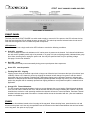
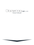
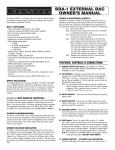
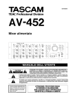
875HT
OWNER’S
MANUAL
IMPORTANT SAFETY INSTRUCTIONS
The lightning flash with arrowhead symbol within an equilateral triangle, is intended to alert the user
to the presence of uninsulated "dangerous voltage " within the product's enclosure that may be of
sufficient magnitude to constitute a risk of electric shock to persons.
The exclamation point within an equilateral triangle is intended to alert the user to the presence of
important operating and maintenance (servicing) instructions in the literature accompanying the
product.
1.
2.
3.
4.
5.
6.
7.
8.
9.
10.
11.
12.
13.
14.
Read these instructions.
Keep these instructions.
Heed all warnings.
Follow all instructions.
Do not use this apparatus near water.
Clean only with dry cloth.
Do not block any ventilation openings. Install in accordance with the manufacturer's instructions.
Do not install near any heat sources such as radiators, heat registers, stoves, or other apparatus (includ
ing amplifiers) that produce heat.
Do not defeat the safety purpose of the polarized or grounding-type plug. A polarized plug has two blades
with one wider than the other. A grounding type plug has two blades and a third grounding prong. The
wide blade or the third prong are provided for your safety. If the provided plug does not fit into your outlet,
consult an electrician for replacement of the obsolete outlet.
Protect the power cord from being walked on or pinched particularly at plugs, convenience receptacles,
and the point where they exit from the apparatus.
Only use attachments/accessories specified by the manufacturer.
Use only with the cart, stand, tripod, bracket, or table specified by the manufacturer, or sold
with the apparatus. When a cart is used use caution when moving the cart/apparatus combi
nation to avoid injury from tip-over.
Unplug this apparatus during lightning storms or when unused for long periods of time.
Refer all servicing to qualified service personnel. Servicing is required when the apparatus
has been damaged in any way, such as power-supply cord or plug is damaged, liquid has been spilled or
objects have fallen into the apparatus, the apparatus has been exposed to rain or moisture, does not oper
ate normally, or has been dropped.
"WARNING: TO REDUCE THE RISK OF FIRE OR ELECTRIC SHOCK, DO NOT EXPOSE THIS APPARATUS
TO RAIN OR MOISTURE".
"DO NOT EXPOSE THIS EQUIPMENT TO DRIPPING OR SPLASHING AND ENSURE THAT NO OBJECTS
FILLED WITH LIQUIDS, SUCH AS VASES, ARE PLACED ON THE EQUIPMENT".
"TO COMPLETELY DISCONNECT THIS EQUIPMENT FROM THE AC MAINS, DISCONNECT THE POWER
SUPPLY CORD PLUG FROM THE AC RECEPTACLE".
"THE MAINS PLUG OF THE POWER SUPPLY CORD SHALL REMAIN READILY OPERABLE".
875HT EIGHT CHANNEL POWER AMPLIFIER
Table of Contents
Important Safety Instructions
General Introduction
Introduction
Description
Shipping Box & Packing Materials
Installation
Wiring the 875HT
Page 1
Front Panel
Power Switch
LED Indicators
Fuses
Page 2
875HT Rear Panel Input/Output Connections
Single Ended Input Connector
Balanced Input Connector
Balanced versus UnBalanced Inputs
Input Select Switch
Stereo/MonoSwitch
Output Binding Posts
Page 3
875HT Rear Panel Input/Output Connections contd.
Ratings Label
Power Inlet
Power-Up Connector
Page 4
Typical 5.1Home Theatre Setup
Page 5
Typical 7.1Home Theatre Setup
Page 6
High Power 7.1 Home Theatre Setup
Page 7
Block Diagram
Page 8
AC Power Control
External Control Voltage Power Up
AC Power Input
Page 9
Technical Specifications
Page 10
Important Warranty Information
Back Cover
875HT-MANUAL-2004-03-24
875HT EIGHT CHANNEL POWER AMPLIFIER
INTRODUCTION
Thank you for choosing the 875 Eight Channel Power Amplifier. Bryston welcomes any suggestions you may have, or
comments regarding the operation of your amplifier. We consider you, our customer, to be Bryston’s most important
resource, and your opinion is very much appreciated.
DESCRIPTION
The 875HT is a modular multi-channel audio power amplifier design of 8 x 75 Watts per channel. It is essentially 4 stereo
amplifiers. Each stereo pair selects from balanced or single ended inputs, and each stereo pair may be bridged to form a
single higher power amplifier channel. The gain of the balanced input is 23dB and the single ended input is 29dB.
The power up sequence of the 875HT may be controlled from a 12v control voltage. The 875 uses ‘soft start’ power control circuitry to eliminate high inrush currents when A/C power is applied.
WARRANTY (see back page for details )
SHIPPING BOX & PACKING MATERIAL
Please keep the original shipping box and all packing material. This will ensure the amplifier is protected in future transport. In the unlikely event you have a problem and must return it for service you must use the proper packing material.
Ship the amplifier only in the original packing material, as the unit is not insurable by carriers otherwise.
INSTALLATION
The most important installation consideration is ventilation. The 875 series amplifiers are a convection-cooled.
Unrestricted air-flow across its heat sinks is a must. For this reason do not install anything directly above it. Allow 3.5” (2u)
to 5” (3u) inches of space above and to the sides of this amplifier. Do not install directly above other heat generating equipment. Any 875 channels thermally shutting down during operation indicates insufficient cooling, and a remedy must be
found for cooling the amplifier. Provide a minimum 6” space to the rear of the 875 for ventilation and dressing cables to
and from the amplifier.
Never operate the 875 in a vertical position.
WIRING THE 875HT (also see rear panel description )
Speaker wires should be as short as practical. Use quality wire, and if runs are more than 3 meters use at least 12 gauge
wire. The speaker binding posts will accept wire up to 3 gauge in size. Bryston can custom build cables for your application.
P A/C power:
Before plugging in the power cord be sure your 875 is specified for the correct A/C voltage for your locality. The
voltage is listed by the power input connector. Never lift the safety ground to the amplifier or remove the ground pin
from the plug.
P
Power line conditioners:
The 875’s performance will not be improved by the use of power line conditioners. In fact most of the time they
restrict the flow of current in the power line to the amplifier thereby reducing performance at high output levels.
1
875HT EIGHT CHANNEL POWER AMPLIFIER
FRONT PANEL OF 875HT-Silver:
FRONT PANEL
POWER switch
The front panel label '875HT POWER’ is a switch used to apply or remove A/C line power to the 875 soft start circuitry.
Push the switch and the 875 will initiate the start up sequence. The switch cap remains indented when circuits are on.
Push the switch again the 875 will initiate the power off sequence.
LED Indicators:
Each 875 channel has a single multi-colour LED indicator to monitor the following conditions:
P
Unlit LED: no power
The 875 channel led when unlit indicates no A/C mains power is present at the channel. If all channel led indicators
are unlit the 875 probably needs only to be powered on. A group of 4 leds not lighting possibly indicates blown group
fuse. When checking fuses, unplug the power cord. Use only the specified fuses for your operating voltage.
See page 6 for the fuse locations.
P
Red LED: muted.
Each channel normally mutes momentarily during power up and power down sequences.
P
Green LED: normal operation
P
Flashing Red LED: Clipping
Clipping occurs when the channel output level no longer can follow the level increase at the input (Over driven input
condition). When a 875 channel is driven into clipping the channel led will change from green to red then back to
green when the level is reduced ( Flashing Red ). Momentary clipping can be tolerated, however it indicates that
maximum un-distorted power has been surpassed and potential speaker damage may result if over load conditions
persist. Any amplifier that is constantly operated into clipping indicates a more powerful amplifier is needed for that
application.
P
Orange LED: Thermal Shutdown
The 875 channel has thermal shutdown circuitry to prevent damage due to over heating. Should thermal shutdown
occur, the both stereo channels will mute, and the channel leds will turn orange indicating this condition. When the
channels have cooled to a safe operating condition the channels will return to normal operation. Persistent Thermal
shutdown indicates steps need to be taken to increase airflow across the channels heat sink. (Also see installation
section on ventilation).
FUSES
There are two fuse holders located at the front edge of the top panel. When checking fuses, power down the unit and
disconnect the power cord. Use only the specified fuses as indicated on the label located between the two fuse holders
on the top panel. See photo at top of page.
2
875HT EIGHT CHANNEL POWER AMPLIFIER
875HT REAR PANEL INPUT/OUTPUT CONNECTIONS
1 Single Ended Input Connectors
This input connector for single-ended or un-balanced signals accepts standard ‘RCA’ or
‘Phono’ connectors.
2 Balanced Input connector.
This input connector accepts standard 3 pin ‘XLR’ male connectors.
Pin 1 is signal ground
Pin 2 is positive phase (+) signal
Pin 3 is negative phase (-) signal
BALANCED vs SINGLE ENDED INPUTS
The balanced input requires a balanced pre-amp source. Balanced systems provide noise protection from external
electrical interference, so cable length can be very long (50m or longer ). The single ended or unbalanced input is
provided for pre-amps without balanced output. Single-ended cables should be kept to 20’ (7m) or less. In general
never use longer cables than necessary, never coil excess cable length, and run signal wires away from AC power
or speaker cables. Whether using balanced or un-balanced cables, use quality, 100% shielded cables with gold
plated connectors.
P Single-ended inputs:
Input Sensitivity:
850mV input for an output of 75W into 8 ohms
P Balanced inputs:
1.7V input for an output of 75W into 8 ohms
3 Input Select Switch.
Each 875-HT channel gives the user the option of switching between either balanced input or single ended input.
4 Input Level Control
Normal or maximum is fully clockwise. Minimum is fully
counter clockwise which fully attenuates the input signal.
LEVEL CONTROL
min.
max.
5 STEREO/MONO SWITCH
The 875HT is configured as 4 stereo amplifiers. Each stereo pair has a Mono/Stereo switch. Stereo configures the chan
nels as independent amplifiers with their own dedicated inputs. Mono configures the stereo pair as a single mono
amplifier. The input comes only from the Mono labeled input and the speaker output connections are between the
two hot (red) binding posts.
6 OUTPUT BINDING POSTS
In STEREO mode: the RED binding post is connected
to the amplifier output. Connect to this post the (+) ter
minal on the loudspeaker. The BLACK binding post is
connected to signal ground. Connect to this post the (-)
terminal on the loud speaker.
In MONO mode: both the RED binding posts are
connected to amplifier outputs. The Odd Numbered
channels (1, 3, 5 or 7) are the positive (+) phase output
and the even numbered channels are the negative (-)
phase output
The Output binding posts provide three different inter
connect options. Combinations may be used when biwiring. See figure below. Cables should be kept as short
as practical and should never be terminated with con
nectors that may become confused for AC power con
nectors. Cables should be dressed away from input and
power cables.
3
875HT - EIGHT CHANNEL POWER AMPLIFIER
P
P
P
BANANA PLUGS offer a quick disconnect option. Before inserting a banana plug into the binding post be sure
to tighten the post nut to avoid rattling and to provide full insertion of the banana plug. Gold plated locking
banana plugs are available from Bryston.
SPADE LUGS provide high contact area and secure fastening. Lugs should be gold plated. See diagram for
details. Post diameter is 5/16’ ( 8mm ),lug width 5/8” (16 mm). Gold plated spade lugs are available from
Bryston.
STRIPPED BARE wire up to 3 gauge can be inserted through the hole in the binding post and held in place by
tightening the post knob. Additional tightening pressure can be achieved using the wrench provided in the slots of
the knob. Do not over tighten or the binding post may become damaged. Note that copper wire is malleable and
may require further tightening after the initial installation.
7 RATINGS LABEL
Contains the exact model name, the electrical ratings for that particular model, as well as the serial number and date
of manufacture date code (yyww)
8 POWER INLET:
Primary or mains power cord input connector (IEC 320 inlet). Connect the supplied power cord to this connector only
after checking the unit label and verifying that the amplifier is set for your local power requirements for A/C voltage
and line frequency.
9 POWER-UP CONNECTOR:
When an external 12v control signal is applied between the 2 ‘IN’ pins on the connector, the amplifier will power up.
When the 875 has powered up the incoming 12v is handed to the ‘OUT’ terminals to turn on other equipment. This
circuit draws 2 ma to turn the 875 on.
4
875HT - EIGHT CHANNEL POWER AMPLIFIER
Typical 5.1 Home
Theatre Setup
5
875HT - EIGHT CHANNEL POWER AMPLIFIER
Typical 7.1 Home
Theatre Setup
6
875HT - EIGHT CHANNEL POWER AMPLIFIER
HIGH POWER 7.1
Home Theatre Setup
7
875HT - EIGHT CHANNEL POWER AMPLIFIER
8
875HT - EIGHT CHANNEL POWER AMPLIFIER
A/C POWER CONTROL
External control voltage power up ( Local / external switch)
To power-up the 875 using an external control voltage, supply a 4v to 12v A/C or DC control voltage to the ‘IN’ terminals
of the “Power-Up” connector. The front panel ‘Power’ switch needs to be off for proper remote operation.
Use paired wire of 22 gauge to 18 gauge between the source device and the 875. The amplifier will now power-up when
the control voltage is present (on).
Immediately following power up, the control voltage will appear at the ’OUT’ terminals of connector for the control of
other equipment.
Removal of the control voltage causes the 875 to turn ‘off’ and the control voltage at the ‘OUT’ terminals is interrupted.
AC power input
This is a high current plug for the power cord receptacle. Check that the voltage rating at the right of the connector conforms with your locality. With the front panel power switch in the off position, insert the power cord into the 875, then plug
the other end to an appropriate A/C power outlet.
Note:
The ‘OUT’ terminals of the “Power-Up” connector are connected to the ‘IN’ terminals once the 875 has powered-up.
The control current that appears across the “OUT” terminals is determined by the source equipment. The carrying current of the ‘OUT’ relay is 2 amps. The 875 itself draws less than 3 ma from the control current when operating.
9
875HT - EIGHT CHANNEL POWER AMPLIFIER
Technical Specifications
Power Output
75 watts per channel into 8 ohms
100 watts per channel into 4 ohms
Gain Select and Sensitivity
29dB - .850Vin = 75W @ 8 Ohms - single ended input
23dB - 1.7Vin = 75W @ 8 Ohms - balanced input
Input Impedance
20 Kohms single ended
40 Kohms balanced
Distortion
IMD or THD+noise
< 0.007% 20Hz to 20kHz at 75 watts into 8 ohms,
< 0.010% 20Hz to 20kHz at 100 watts into 4 ohms
Noise
Measured with input shorted - 20Hz to 20kHz.
>105dB below rated output 29dB gain (- 68dBu)
>107dB below rated output 23dB gain (- 70dBu)
Slew Rate
>60 volts per microsecond
Power Bandwidth
<1 Hz to over 100 kHz
Damping Factor
Over 500 at 20 Hz, ref. 8 ohms
Dimensions
W D H: - 19 (or 17) x 19 x 3.5 inches ( 2 rack spaces )
Weight:
approx.. 25kg - 55 lbs.
Power Consumption &Heat Load
max power
typical use
single channel 75W @ 8 ohms 8 channels @ 75W @ 8 ohms Max. Heat Dissipation 8 ohms -
150 Watts
1200 Watts
2400 Btu/Hr.
15 Watts
120 Watts
240 Watts
single channel 100W @ 4 ohms 8 channels @ 100W @ 4 ohms Max. Heat Dissipation 4 ohms At Idle -
210 Watts
1680 Watts
3500 Btu/Hr.
110 Watts
21 Watts
168 Watts
350 Watts
10
BRYSTON 20 -YEAR WARRANTY
Bryston products are warranted to be free from
manufacturing defects for a minimum of twenty
years from the original date of manufacture. This
includes parts, labour and return shipping to the
first owner and all subsequent owners. Warranty
coverage is automatic and commences with the
original date of manufacture which is kept on file at
Bryston.
In the event of a defect or malfunction, Bryston will
remedy the problem by repair or replacement, as
we deem necessary, to restore the product to full
performance.
This warranty is considered void if the defect, malfunction or failure of the product or any component
part was caused by damage ( not resulting from a
defect or malfunction ) or abuse while in the possession of the customer. Tampering by persons
other than factory authorized service personnel, or
failure to fully comply with Bryston operating
instructions, voids the warranty.
This warranty gives you specific legal rights and
you may also have other rights which may vary
from province to province and country to country.
BRYSTON SERVICE CANADA:
24 STEINWAY BLVD., UNIT 48
ETOBICOKE, ONTARIO
CANADA M9W 6T8
BRYSTON SERVICE USA:
79 COVENTRY ST., SUITE #5
NEWPORT VERMONT.
U.S.A. 05855-2100
PHONE: 416-675-2585
FAX: 416-675-3103
E-mail: [email protected]
PHONE: 802- 334-1201
FAX: 802-334-6658
E-mail: [email protected]
BRYSTON SERVICE OUTSIDE CANADA & the USA:
CONTACT YOUR LOCAL DISTRIBUTOR
OR
CHECK OUR WEB SITE: www.bryston.ca
E-MAIL BRYSTON DIRECTLY: [email protected]
FAX BRYSTON DIRECTLY:
705-742-0882
PHONE BRYSTON DIRECTLY:
705-743-5325
BRYSTON LTD., 677 NEAL DRIVE, P.O. BOX 2170, PETERBOROUGH, ONTARIO CANADA K9J 7Y4