1
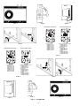
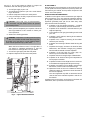
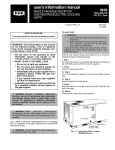
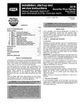
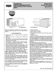
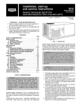
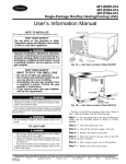
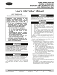
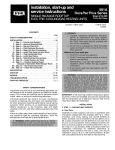
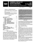
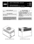
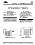
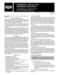
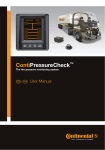
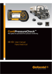
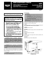
user’s information manual
SINGLE PACKAGE ROOFTOP
GAS HEATING/
ELECTRIC COOLING UNITS
581B
DuraPac Plus Series
Sizes 036-150
3 to 121/2 Tons
Cancels: OM11-19
NOTE TO INSTALLER:
This manual should be left with the equipment owner.
WARNING: If the information in this manual
is not followed exactly, a fire or explosion
may result causing property damage, personal injury or loss of life.
— Do not store or use gasoline or other
flammable vapors and liquids in the
vicinity of this or any other appliance.
— WHAT TO DO IF YOU SMELL GAS
• Do not try to light any appliance.
• Do not touch any electrical switch; do
not use any phone in your building.
• Immediately call your gas supplier from a
neighbor’s phone. Follow the gas supplier’s instructions.
• If you cannot reach your gas supplier,
call the fire department.
— Installation and service must be performed
by a qualified installer, service agency or
the gas supplier.
WARNING: Improper installation, adjustment,
alteration, service, or maintenance could cause property damage, serious injury or death. Refer to this
manual. For assistance or additional information,
consult a qualified installer, service agency, or the
gas supplier.
OM11-22
3/15/02
TO LIGHT UNIT
WARNING:
1. Do not attempt to light by hand; personal injury
may result.
2. Before attempting to start the gas heating section, familiarize yourself with all the procedures that must be followed.
If you do not follow these instructions exactly, a fire or
explosion may result. Property damage, injury, or loss
of life could occur.
See Fig. 1 for location of gas valve. Refer to Fig. 2 while
proceeding through the following steps.
I. Step 1
Set room thermostat to the lowest temperature setting and
set SYSTEM switch to HEAT or AUTO. position.
II. Step 2
Close the manual gas valve.
III. Step 3
Turn off the electrical supply to the unit and install lockout
tag.
IV. Step 4
Remove the burner access panel.
V. Step 5
Move the control on the gas valve to the OFF position and
wait 5 minutes.
VI. Step 6
Move control on gas valve to ON position.
WARNING: Before
performing
recommended
maintenance, be sure main power switch to unit is
turned off. Electrical shock could cause serious injury
or death.
Your rooftop combination heating/cooling unit is equipped
with an automatic direct-spark ignition and induced-draft
combustion blower.
WARNING: Do not attempt to light by hand; serious injury or death may result.
Fig. 1 — Typical Gas Valve Location
(581B090 Shown)
MAIN
ON
OFF
LOCK-OUT
TAG
STEP 3
STEP 2
STEP 1
SINGLE-STAGE VALVE
EW
L
O
WR
S
CE CR
TWO-STAGE GAS VALVE
WR
C2
P3
O
F
F
ON
M1
ON
C
O
F
F
HI
M
REPLA
STEP 5
California Compliant 3-Phase
581B036-060071
581B036-060114
581B048,060149
Single Phase
581B036-060072
581B036-060115
581B048,060150
Low NOx
581B036-060060N
581B036-060090N
581B048,060120N
STEP 7
STEP 6
STEP 8
STEP 10
STEP 9
Fig. 2 — To Light Unit
—2 —
C2
P3
O
F
F
L
O
S
CE CR
EW
3-Phase Models
581B036-072072
581B036-072115
581B048-072150
581B090-102125
581B090-120180
581B090-150224
581B120-150250
ON
M1
ON
C
O
F
F
HI
M
REPLA
SINGLE-STAGE VALVE
TWO-STAGE GAS VALVE
California Compliant 3-Phase
581B036-060071
581B036-060114
581B048,060149
Single Phase
581B036-060072
581B036-060115
581B048,060150
Low NOx
581B036-060060N
581B036-060090N
581B048,060120N
3-Phase Models
581B036-072072
581B036-072115
581B048-072150
581B090-102125
581B090-120180
581B090-150224
581B120-150250
STEP 4
Open the manual gas valve.
Should overheating occur, or the gas supply fail to shut off,
shut off the manual gas valve to the unit before shutting off
the electrical supply.
Do not use this unit if any part has been under water. Immediately call a qualified service technician to inspect the unit
and to replace any part of the control system and any gas
control which has been under water.
X. Step 10
MAINTAINING YOUR UNIT
Set room thermostat selector slightly above room temperature to start unit. The induced-draft combustion air fan will
start. Main gas valve will open and main burners should
ignite within 5 seconds. If the burners do not light, there is a
22-second delay before another 5-second try. If the burner
still does not light, the time delay is repeated. If the burner
does not light within 15 minutes, there is a lockout. If burners still do not light, call for service.
All maintenance should be handled by skilled, experienced
personnel. Your dealer can help you establish a standard
procedure.
For your safety, keep the unit area clear and free of combustible materials, gasoline, and other flammable liquids and
vapors.
VII. Step 7
Replace the burner access panel.
VIII. Step 8
Turn on the electrical supply to unit.
IX. Step 9
WARNING: If the main burners fail to light, or the
blower fails to start, shut down gas heating section and
call your dealer for service. Failure to follow these
requirements could result in serious injury or death.
XI. Step 11
Set the temperature selector on the room thermostat to desired setting.
TO SHUT UNIT OFF
WARNING:
1. Do not turn off the electrical power to unit without first turning off the gas supply.
2. Never attempt to manually light the main
burners on unit with a match, lighter, or any
other flame. If the electric sparking device fails
to light the main burners, refer to the following
shutdown procedures. Call your dealer as soon
as possible.
Failure to follow these procedures could result in serious fire or serious injury or death.
To ensure proper functioning of the unit, flow of combustion
and ventilating air must not be prevented from reaching the
unit.
To ensure proper airflow, clearance to the condenser coil
should be 36 in. on one side and 12 in. on the other. Either
side may receive the greater clearance. A clearance of 1 in.
from the bottom of the unit to combustible surfaces must be
maintained when not using a roof curb. A clearance of 0 in.
from the bottom of the base rail to combustible surfaces must
be maintained when not using a roof curb. A 60-in. clearance
above the unit must be allowed for proper condenser fan
operation.
A clearance of 42 in. should be allowed on the unit control
box side. When ungrounded surfaces are present, allow a
36-in. clearance between unit and the ungrounded surfaces.
Allow 42 in. between the unit and block or concrete walls or
other grounded surfaces.
Clearance of 48 in. must be maintained between flue side
and combustible surfaces.
ROUTINE MAINTENANCE AND CARE
FOR THE EQUIPMENT OWNER
Consider the following information before maintaining or
servicing equipment:
WARNING:
Refer to Fig. 3 while proceeding with the following steps:
1. TURN OFF GAS SUPPLY AND THEN ELECTRICAL POWER TO YOUR UNIT BEFORE
SERVICING OR PERFORMING MAINTENANCE.
I. Step 1
Set room thermostat to lowest temperature setting and set
SYSTEM switch to OFF position.
2. DO NOT turn off electrical power to this unit
without first turning off the gas supply.
II. Step 2
Close the external manual gas valve.
3. When removing access panels or performing
maintenance functions inside your unit, be
aware of sharp sheet metal parts and screws.
Although special care has been taken to reduce
sharp edges to a minimum, be extremely careful when handling parts or reaching into the
unit.
Failure to follow these instructions could result in serious fire or serious injury or death.
III. Step 3
Turn off the electrical power supply to unit and install lockout tag.
IV. Step 4
Remove the burner access panel.
V. Step 5
Move the control on the gas valve to the OFF position.
VI. Step 6
Replace the burner access panel.
I. AIR FILTERS
VII. Step 7
If unit is being shut down because of a malfunction, call your
dealer as soon as possible.
Air filter(s) should be checked at least every 3 or 4 weeks and
changed or cleaned when necessary. Table 1 indicates the
correct filter size for your unit. See Fig. 4 for filter access
door location.
If unit is being shut down because the heating season has
ended, restore electrical power to the unit to ensure operation of the cooling system during the cooling season.
—3 —
MAIN
ON
OFF
LOCK-OUT
TAG
STEP 2
STEP 3
SINGLE-STAGE VALVE
EW
L
O
S
CE CR
TWO-STAGE GAS VALVE
WR
STEP 1
STEP 4
STEP 7
Fig. 3 — To Shut Unit Off
—4 —
C2
P3
O
F
F
California Compliant 3-Phase
581B036-060071
581B036-060114
581B048,060149
Single Phase
581B036-060072
581B036-060115
581B048,060150
Low NOx
581B036-060060N
581B036-060090N
581B048,060120N
STEP 5
STEP 6
ON
M1
ON
C
O
F
F
HI
M
REPLA
3-Phase Models
581B036-072072
581B036-072115
581B048-072150
581B090-102125
581B090-120180
581B090-150224
581B120-150250
person before each heating season and cleaned when necessary. This checkout should not be attempted by anyone who
does not have the required licensing, expertise and/or equipment to do the job properly. Checking and/or cleaning the heat
exchanger involves removing the gas controls assembly and
the flue collector box cover. When finished, the gas controls
assembly must be reinstalled for proper operation. Also, the
flue collector box cover must be replaced correctly so that a
proper seal is maintained. Contact your dealer for the
required periodic maintenance.
FILTER ACCESS PANEL
Fig. 4 — Typical Filter Access Panel Location
(581B090 Shown)
To replace or inspect filters:
1. Lift up and remove filter access panel.
2. While holding filter, tilt upper filter track.
3. Remove filters by pulling up and out toward you from
the track.
4. Inspect or replace filters.
5. Place filters back in the filter tracks. When installing
filters, note the direction of airflow arrows on the filter frame.
6. Reinstall filter access panel.
If you have difficulty locating your air filter or if you have
questions concerning proper filter maintenance, contact your
dealer for additional instructions. When replacing your
unit’s filters, always use the same size and type of filter that
was originally supplied by the installer.
Units with outdoor air capability have a cleanable filter for
the outdoor air. This filter should be checked annually and
cleaned as necessary with steam or hot water and a mild
detergent. Do not use throwaway filters in place of cleanable
filters.
WARNING: Never operate your unit without filters in place. Failure to heed this warning may result
in damage to the blower motor and/or compressor. An
accumulation of dust and lint on internal parts of your
unit can cause loss of efficiency and, in some cases, fire
that could result in serious injury or death.
Table 1 — Indoor-Air Filter Data
UNIT SIZE
581B
036-072
090,102
120,150
INDOOR AIR FILTERS
(Throwaway Fiberglass)
Quantity
Size (in.)
2
16 x 25 x 2
4
16 x 20 x 2
4
20 x 20 x 2
NOTE: See unit Installation Instructions if optional filters are used.
When replacing filters, always use the same type and size originally
supplied.
III. FANS, BELTS, AND FAN MOTOR
At the beginning of each heating and cooling season, check the
condition of fan wheels and housings, belt tension, and fan
motor shaft bearings. No lubrication of condenser or evaporator fan bearings or motors is required or recommended.
IV. EVAPORATOR AND CONDENSER COILS
Inspect and clean the condenser and evaporator coils at the
beginning of each cooling season, or more frequently as conditions require.
Cleaning of the coils should only be done by qualified service
personnel. Contact your dealer for the required annual
maintenance.
V. CONDENSATE DRAIN
The drain pan, condensate trap, and drain line should be
checked and cleaned at the same time the cooling coils are
checked by your dealer.
VI. COMPRESSOR
All compressors are factory-supplied with a normal charge of
the correct type of refrigeration-grade oil and should not require additional oil.
VII. CONDENSER FAN
WARNING: Do not poke sticks, screwdrivers, or
any other object into revolving fan blades. Severe
bodily injury could result.
The fan must be kept free of all obstructions to ensure proper
cooling. Contact your dealer for any required service.
VIII. ELECTRICAL CONTROLS AND WIRING
Electrical controls are difficult to check without proper
instrumentation. If there are any discrepancies in the operating cycle, contact your dealer and request service.
IX. REFRIGERANT CIRCUIT
The refrigerant circuit is difficult to check for leaks without
the proper equipment. If inadequate cooling is suspected,
contact your dealer for service.
X. COMBUSTION AREA AND VENT SYSTEM
The combustion area and vent system should be visually
inspected before each heating season. The normal accumulation of dirt, soot, rust, and scale can result in loss of efficiency and improper performance if allowed to build up.
CAUTION: If your unit makes unusual or especially loud noises during heating, shut down the heating section and call your qualified Bryant dealer.
II. HEAT EXCHANGER
To ensure dependable and efficient heating operation, the
heat exchanger should be checked by a qualified maintenance
—5 —
See Fig. 1 and 5 and proceed as follows to inspect the
combustion area and venting system of your unit.
1. Turn off gas supply to your unit.
2. Turn off electrical power to your unit. Install lockout
tag on disconnect.
3. Remove compressor and burner access panels.
4. Using a flashlight, carefully inspect the burner areas
for dirt, soot, rust, or scale.
CAUTION: If dirt, soot, rust, or scale accumulations are found, call your dealer and do not operate
your heating section.
5. When you have completed your inspection, follow the
start-up procedures in this manual to restore your
unit to operation.
6. Observe unit heating operation.
WARNING: Components in heating section may be
hot after unit has been started. When observing flame,
be careful not to get close to or touch heating components. Serious personal injury could result.
Watch the burner flame to see if it is bright blue. If
you observe a suspected malfunction or that the
burner flame is not bright blue, call your dealer.
XI. UNIT PANELS
After performing any maintenance or service on the unit, be
sure all panels are securely fastened in place to prevent rain
from entering unit cabinet and to prevent disruption of the
correct unit airflow pattern.
REGULAR DEALER MAINTENANCE
In addition to the type of routine maintenance you might be
willing to perform, your unit should be inspected regularly
by a properly trained and qualified service technician. An
inspection (preferably each year, but at least every other
year) should include the following:
1. Inspection of all flue product passages — including
the burners, heat exchanger, and flue collector box.
2. Inspection of all combustion- and ventilation-air passages and openings.
3. Close inspection of all gas pipes leading to and inside
your unit.
4. Inspection, and if required, cleaning of the condenser
and evaporator coils.
5. Inspection and, if required, cleaning of the condensate drain pan and trap.
6. Inspection and cleaning of blower wheel housing and
motor.
7. Inspection of all supply- and return-air ducts for leaks,
obstructions, and insulation integrity. Any problems
found should be resolved at time of inspection.
7. Turn off unit gas supply and electrical power.
8. Replace compressor and burner access panels.
8. Inspection of the unit base for cracks, gaps, etc.,
which may cause a hazardous condition.
9. Inspection of the unit casing for signs of deterioration.
10. Inspection of all electrical wiring and components to
ensure proper connection.
11. Inspection for leaks in the refrigerant circuit. Pressurecheck to determine appropriate refrigerant charge.
12. Inspection and cleaning of fan wheels and housings,
belt tension, and fan motor and shaft bearings.
13. Operational check of the unit to determine working
conditions. Repair or adjustment should be made at
the time of inspection.
Your servicing dealer may offer an economical service
contract that covers seasonal inspections. Ask for further details.
Complete service instructions can be found in the base unit
Installation, Start-Up and Service Instructions.
Fig. 5 — Typical Heat Section Detail
—6 —
BEFORE YOU CALL FOR SERVICE, CHECK FOR
SEVERAL PROBLEMS THAT CAN BE EASILY SOLVED
power supply to the unit. Remove the compressor access
panel.
If insufficient heating or cooling is suspected:
( ) Check for sufficient airflow. Check the air filter for dirt.
Check for blocked return- or supply-air grilles. Be sure they
are open and unobstructed. If these checks do not reveal the
cause, call your servicing dealer.
If your unit is not operating at all, check the following list for
easy solutions:
( ) Check to be sure that your thermostat temperature selector is set above the indoor temperature during the heating
season, or below the indoor temperature during the cooling
season. Be sure the SYSTEM switch is in the proper HEAT,
COOL, or AUTO. position and not in the OFF position.
( ) During the heating season, check the control switch on
the gas valve. Is it in the ON position? If it is not, be sure it
has not been turned off as a safety precaution. If no safety
hazards are present, follow the start-up procedures in this
manual.
( ) If your unit still fails to operate, call your servicing
dealer for troubleshooting and repairs. Specify the model
and serial numbers of your unit. (Record them in this manual in the space provided.) If the dealer knows exactly which
unit you have, he may be able to offer suggestions over the
phone, or save valuable time through knowledgeable preparation for the service call.
( ) Is the electrical supply switch ON? Are any fuses blown
or has the circuit breaker tripped?
IN CASE OF TROUBLE
If after performing the above routine checks, unit performance is unsatisfactory, shut off the unit and call your
dealer.
( ) During the heating season, check the external manual
shutoff valve. Is this lever parallel with the pipe, indicating
that the valve is open? Or is the lever at a right angle, indicating that the valve is closed? If closed, has the gas been shut
off for safety reasons? Otherwise, you may open the valve and
follow the start-up procedures listed in this manual.
NOTE: Before proceeding with the next check, shut OFF the
gas supply to the unit and then turn OFF the electrical
Dealer’s Name _________________________________________
Telephone _____________________________________________
Unit Model ____________________________________________
Unit Serial Number ____________________________________
—7 —
Bryant Heating & Cooling Systems
FOR SERVICE OR REPAIR, FOLLOW THESE STEPS IN ORDER:
FIRST:
Contact the installer. You may find his name on the product or in your
Homeowner's Packet. If the installer’s name is not known, call your builder if
yours is a new residence.
SECOND: Contact the nearest distributor. (See telephone yellow pages.)
THIRD: Contact:
BRYANT HEATING & COOLING SYSTEMS
Consumer Relations Department
P.O. Box 4808
Syracuse, New York 13221
Phone: 1-800-428-4326
Model No.
Unit Serial No.
Date of Installation
Installed by
Name of Owner
Address of Installation
Outdoor Cooling or Heating-Cooling Product
(Units Smaller Than 185,000-Btuh Cooling Capacity)
Limited Warranty
ONE-YEAR LIMITED WARRANTY — Bryant Heating & Cooling Systems (hereinafter referred to as “Company”) warrants this product to be free from defects in
material and workmanship. If a defect is found within one year from date of
original installation of product (whether or not actual use begins on that date)
Company will provide a new or remanufactured part, at Company’s sole option,
to replace any defective part, without charge for the part itself.
TEN-YEAR LIMITED WARRANTY ON HEAT EXCHANGER ONLY — If a defect
is found in the heat exchanger within ten years from the date of original installation of product, Company will either provide a new or remanufactured heat
exchanger, without charge for the part itself, or at Company’s option, allow a
credit in the amount of the then factory selling price for a new equivalent heat
exchanger toward the retail purchase price of a new Bryant unit.
FIVE-YEAR LIMITED WARRANTY ON COMPRESSOR ONLY — If a defect is
found in the compressor within five years from the date of original installation of
product, Company will provide a new or remanufactured compressor, at the
Company’s sole option, to replace any defective compressor, without charge for
the part itself.
FIVE-YEAR LIMITED WARRANTY ON ELECTRICAL ELEMENT FOR AIR
HEATING ONLY — If a defect is found in any electrical element within five years
from the date of original installation of product, Company will provide a new or
remanufactured electrical element, at the Company’s sole option, to replace
defective electrical element, without charge for the part itself.
None of these warranties include labor or other costs incurred for diagnosing,
repairing, removing, installing, shipping, servicing or handling of either defective
parts, or replacement parts, or new units.
WARRANTY CONDITIONS:
1. Warranties apply only to products in their original installation location.
2. Installation, use, care, and maintenance must be normal and in accordance
with instructions contained in the Owner’s Manual and Company’s service
information.
3. Defective parts must be returned to the distributor through a registered servicing dealer for credit.
4. All work shall be performed during normal working hours.
LIMITATION OF WARRANTIES — ALL IMPLIED WARRANTIES (INCLUDING
IMPLIED WARRANTIES OF MERCHANTABILITY AND FITNESS FOR A PARTICULAR PURPOSE) ARE HEREBY LIMITED IN DURATION TO ONE YEAR.
SOME STATES DO NOT ALLOW LIMITATIONS ON HOW LONG AN IMPLIED
WARRANTY LASTS, SO THE ABOVE MAY NOT APPLY TO YOU. THE
EXPRESS WARRANTIES ARE EXCLUSIVE AND MAY NOT BE ALTERED,
ENLARGED, OR CHANGED BY ANY DISTRIBUTOR, DEALER, OR OTHER
PERSON WHATSOEVER.
COMPANY WILL NOT BE RESPONSIBLE FOR:
1. Normal maintenance as outlined in the installation and servicing instructions
or Owner’s Manual, including filter cleaning and/or replacement and
lubrication.
2. Damage or repairs required as a consequence of faulty installation, misapplication, abuse, improper servicing, unauthorized alteration or improper
operation.
3. Failure to start due to voltage conditions, blown fuses, open circuit breakers,
or damages due to the inadequacy or interruption of electrical service.
4. Damage as a result of floods, winds, fires, lightning, accidents, corrosive environments or other conditions beyond the control of Company.
5. Parts not supplied or designated by Company, or damages resulting from their
use.
6. Company products installed outside the continental U.S.A., Alaska, Hawaii,
and Canada.
7. Electricity or fuel costs, or increases in electricity or fuel costs from any
reason whatsoever, including additional or unusual use of supplemental electric heat.
8. ANY SPECIAL INDIRECT OR CONSEQUENTIAL PROPERTY OR COMMERCIAL DAMAGE OF ANY NATURE WHATSOEVER. Some states do not
allow the exclusion of incidental or consequential damages, so the above
limitation may not apply to you.
This Warranty gives you specific legal rights, and you may also have other rights which vary from state to state.
Catalog No. 5358-110
Effective on product manufactured after July 1, 1987. Supersedes any other warranty certificates supplied with the product.
Copyright 2002 Bryant Heating and Cooling Systems
39004DP247
CATALOG NO. 5358-111