1
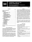
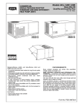
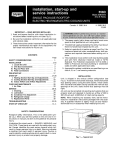
installation, start-up and
operating instructions
COMMERCIAL THERMOSTAT
(P/N TSTATBBPCM01-A)
Cancels: New
IMPORTANT: Read entire instructions before starting the
installation.
SAFETY CONSIDERATIONS
Read and follow manufacturer instructions carefully. Follow
all local electrical codes during installation. All wiring must
conform to local and national electrical codes. Improper wiring or installation may damage thermostat.
Recognize safety information. This is the safety alert symbol
. When the safety alert symbol is present on equipment
or in the instruction manual, be alert to the potential for personal injury.
Understand the signal words DANGER, WARNING, and CAUTION. These words are used with the safety alert symbol.
DANGER identifies the most serious hazards which will result in severe personal injury or death. WARNING signifies
a hazard which could result in personal injury or death. CAUTION is used to identify unsafe practices which would result
in minor personal injury or property damage.
GENERAL
Bryant’s 7-day, commercial, programmable thermostats are
wall-mounted, low-voltage thermostats which maintain room
temperature by controlling the operation of an HVAC (heating, cooling and ventilation) system. Separate heating and
cooling set points and auto-changeover capability allow occupied and unoccupied programming for energy savings.
All thermostats allow up to 4 time/temperature settings to
be programmed per 24-hr period. Each thermostat stores programs for 7 independent days. Batteries are not required. During power interruption the internal memory stores comfort
schedules for an unlimited time while the clock continues to
run for at least 72 hours.
The thermostat can be configured to accept several different
equipment configurations, from single-stage heating and cooling to 3 stages of heating and 2 stages of cooling. The thermostat comes factory configured for 1 stage of cooling and
1 stage of heating.
INSTALLATION
I. THERMOSTAT LOCATION
The thermostat should be mounted:
• approximately 5 ft from the floor
• close to or in a frequently used room, preferably on an inside partitioning wall
• on a section of wall without pipes or ductwork
The thermostat should not be mounted:
• close to a window, on an outside wall, or next to a door
leading to the outside
• where exposed to direct light and heat from a lamp, the
sun, a fireplace, or any other temperature-radiating object
which may cause a false reading
• close to or in direct airflow from supply registers or return
air grilles
• in areas with poor air circulation (such as behind a door or
in an alcove)
II TSTAT-1
6/15/96
II. SET DIP SWITCHES
There are 4 small switches on the back of the circuit board
which must be configured by the installer. The ON position
is indicated by small letters on the switch. Ignore the numbers (1-4) on the switch. The switch designation (A-D) is printed
on a sticker next to the switch. To change a switch position,
use the corner of a small screwdriver to slide the switch
ON or OFF. Set the DIP switches before installing the
thermostat.
A. Air Conditioner or Heat Pump Selection (Switch A)
Use switch A to select between air conditioning and heat pump
applications. A heat pump application uses a reversing valve.
Set switch A to OFF for air conditioning applications (no reversing valve). Set switch A to ON for heat pump applications (O is used to energize the reversing valve). The factory
setting is OFF.
B. Compressor Stage Selection (Switch B)
Switch B is used to select between a single-stage and a 2-stage
compressor. Set switch B to OFF for a single-stage compressor. Set switch B to ON for a 2-stage compressor. The factory
setting is OFF.
C. Outdoor Air or Remote Room Sensor (Switch C)
Switch C is used to configure the thermostat to work with
either a outdoor air sensor or a remote room sensor. The sensor for the application must be connected to terminals S1 and
S2 of the thermostat. Set switch C to OFF for a outdoor air
sensor. Set switch C to ON for a remote room sensor. The factory setting is OFF.
D. Averaging of Sensors (Switch D)
Switch D is used if a remote room sensor is being used (switch C
set to ON). The remote room sensor reading can be averaged
with the sensor reading of the thermostat. Set switch D to
OFF if averaging is not required. To average the readings of
the thermostat and remote room sensors, set switch D to ON.
The factory setting is OFF.
III. INSTALL THERMOSTAT
WARNING: Before installing thermostat, turn off all
power to the unit. There may be more than one power
disconnect. Electrical shock can cause injury or death.
1. Turn off all power to unit.
2. If an existing thermostat is being replaced:
a. Remove existing thermostat from the wall.
b. Disconnect wires from existing thermostat. Do not
allow wires to fall back into the wall. As each wire
is disconnected, record wire color and terminal
connection.
c. Discard or recycle old thermostat.
NOTE: Mercury is a hazardous waste and must be disposed
of properly.
3. Open thermostat rear door (mounting base) to expose
mounting holes.
4. Route thermostat wires through large hole in mounting base. Remove outer sheath from wires for added
flexibility.
5. Level mounting base against wall and mark wall through
the 2 mounting holes in base.
6. Drill two 3⁄16-in. mounting holes in wall where marked.
CAUTION: Be careful not to drill into wiring in wall.
Electrical shock could result.
present), electric heat can be locked out if the outdoor ambient temperature rises above the user-defined value. Temperatures of 15 to 55 F (in 5-degree increments) can be selected.
The lockout can also be disabled. The default is OF (disabled). Emergency heat mode disables this function. Press the
Copy Previous Day button in the configuration mode to access the parameter. Use the Up and Down buttons to increase or decrease the setting.
D. Clean Filter Timer Selection
The clean filter selection determines how many hours of blower
operation will pass before the Clean Filter message is displayed. A timer in the thermostat accumulates the total blower
operation hours. The range of values is 400 to 3600 hours (in
400-hour increments).
7. Secure mounting base to wall with 2 screws and anchors provided. Ensure all wires exit through hole in
mounting base.
8. Adjust wire length and routing to allow proper closure
of the thermostat. Strip each wire at the end no more
than 1⁄4-in. to prevent adjacent wires from shorting together. Match and connect wires to terminals on the
thermostat. See Fig. 1-4.
CAUTION: Improper wiring or installation may cause
damage to the thermostat. Check to ensure wiring is
correct before proceeding with installation of unit.
9. Push excess wiring into wall. Seal hole in wall to prevent drafts.
10. Close thermostat door.
11. Turn on power to unit. The thermostat will receive power
from the unit.
On power up the thermostat display shows the selected setup
mode (AC - single-stage air-conditioner, HP - single-stage heat
pump, A2 - 2-stage air conditioner, H2 - 2-stage heat pump)
for a few seconds, depending on DIP switch settings.
IV. SET THERMOSTAT CONFIGURATION
Configuration options, like DIP switch settings, are intended
to be selected at installation and are not normally modified
by the user. These options are not discussed in the owner’s
manual and must be done as part of the installation. A special procedure for the thermostat allows entry into the configuration mode. To enter configuration mode, press and hold
the fan button for approximately 10 seconds. The room temperature display will disappear and dashes (--) will be displayed on the thermostat screen. The thermostat will automatically exit configuration mode if no button is pressed for
10 seconds. Seven different configurations can be set in configuration mode.
A. Fahrenheit or Celsius Selection
The thermostat can be set to use a Celsius or Fahrenheit temperature display. Press the Change Day button in configuration mode to access the parameter. Use the Up and Down
buttons on the thermostat to change the setting between F
(Fahrenheit) and C (Celsius). The default value is F.
B. Fan ON or OFF When Heat is Energized Selection
The thermostat can be set to turn the fan (G output) on or off
when the heat input (terminal W) is energized. Press the Hold
button while in configuration mode to access the parameter.
Use the Up and Down buttons to toggle between OF (fan off
during heating) and ON (fan on during heating). The default
value is OF.
C. High Ambient Electric Heat Lockout Selection
If DIP switch A is set to ON (heat pump application) and DIP
switch C is set to OFF (an outdoor temperature sensor is
—2—
• a ‘‘1’’ will be displayed for 400 hours of operation
• a ‘‘2’’ will be displayed for 800 hours of operation
• a ‘‘3’’ will be displayed for 1200 hours of operation
• a ‘‘4’’ will be displayed for 1600 hours of operation
• a ‘‘5’’ will be displayed for 2000 hours of operation
• a ‘‘6’’ will be displayed for 2400 hours of operation
• a ‘‘7’’ will be displayed for 2800 hours of operation
• a ‘‘8’’ will be displayed for 3200 hours of operation
• a ‘‘9’’ will be displayed for 3600 hours of operation
The selection can also be set to OF (disabled). Press the
Reset Filter button in the configuration mode to access the
parameter. Use the Up and Down buttons to change the setting. The default is 2 (800 hours).
NOTE: During the selection procedure, the Clean Filter message will be displayed, even if OF (disabled) is chosen.
E. Anticipator Adjustment Selection
The anticipator adjustment controls the sensitivity and cycle
rate of the thermostat. Higher numbers decrease the sensitivity and slow the cycle rate. Lower numbers increase sensitivity and speed up the cycle rate. A limiting feature of the
thermostat will not allow more than 4 equipment cycles per
hour, regardless of the anticipator setting. Values can range
from 1 to 9. The default is 3. The default selection will provide optimum performance in nearly all installations. Do not
change the setting unless there is a need to do so. Press the
Mode button during configuration mode to change the setting. Use the Up and Down buttons to increase or decrease
the value.
Unlike conventional thermostat anticipators, the setting is
not determined by current draw. There is no need to measure, know, or compensate for the current. There is no need
to ‘‘droop’’ with this thermostat, regardless of the anticipator
setting.
F. Keypad Lockout Selection
The thermostat has a lockout feature which will not acknowledge configuration buttons until the lockout code is entered.
After the lockout code has been entered, the keypad will remain unlocked until the user has stopped pressing keys for
2 minutes. The Lockout selection can be set to ON or OF (disabled). Press the Set Time key in configuration mode to change
the setting. Use the Up or Down buttons to toggle between
off and on. The default is OF.
NOTE: If the lockout function is enabled, the user can only
disable the lockout by pressing the correct buttons, in order,
within a 10-second time period. The button sequence is: press
the Mode button; press the Copy Previous Day button; press
the Set Time button; and press the Hold button. The lockout
will then be disabled until the user stops pressing buttons
for 2 minutes.
CONNECTION
BOARD
O/W2
R
Y1
Y1
R
Y2
G
W1
Y/Y2
W2
W/W1
G
C
X*
C
B
548D036-120
549B036-120
551B036-150
558D036-150
580D036-150
581B036-150
L
DO NOT USE
S1
S2
COMMERCIAL
THERMOSTAT
*Does not apply to 558D and 580D036-150 units.
NOTES:
1. 558D and 580D036-072 units only have one stage of cooling, but
can have 2 stages of heat. In these applications set DIP switch B
to ON for 2-stage operation.
2. For 548D and 549B heat pump applications, set switch A to OFF
(air conditioning). The 548D and 549B units do not have an ‘‘O’’
terminal.
Fig. 1 — Thermostat Wiring (548D036-120; 549B036-120; 551B036-150;
558D036-150; 580D036-150; 581B036-150)
TB2
O/W2
W2
Y1
W1
R
R
G
C
Y/Y2
Y1
W/W1
Y2
G
X
C
B
551A155-240
559E180-240
559F180-300
579E180-240
579F180-300
581A155-240
L
DO NOT USE
S1
S2
COMMERCIAL
THERMOSTAT
Fig. 2 — Thermostat Wiring (551A155-240; 559E180-240; 559F180-300;
579E180-240; 579F180-300; 581A155-240)
—3—
TB2
O/W2
RC
Y1
R
RH
2
W1
4
FIELD RELAY
G
W2
Y/Y2
Y1
W/W1
Y2
G
C
C
B
C2
FIELD
RELAY
C1
X
L
11
DO NOT USE
S1
542J150 and 180
S2
NOTES:
1. Field relay P/N HN61KK224.
2. Set switch A to OFF (air conditioning). The 542J units do not have an
‘‘O’’ terminal.
COMMERCIAL
THERMOSTAT
Fig. 3 — Thermostat Wiring (542J150 and 180)
TB3
O/W2
W2
Y1
W1
R
R
G
C
Y/Y2
Y1
W/W1
Y2
G
X
C
B
558G,H240-360
580G,H240-360
L
DO NOT USE
S1
S2
COMMERCIAL
THERMOSTAT
Fig. 4 — Thermostat Wiring (558G,H240-360 and 580G,H240-360)
—4—
G. Low Ambient Cooling Lockout Selection
The Low Ambient Cooling Lockout feature will lock out cooling mode if the outdoor-air temperature is below the lockout
cooling temperature (user-configured).
NOTE: This configuration is not available if DIP switch C (Remote Room Sensor) is set to ON or if the outdoor-air sensor is
in error.
The default is OF (disabled). The lockout temperature can be
set to OF (disabled) or 20 to 60 F in 5-degree increments (enabled). To configure the selection, press the Program button
in the configuration mode. Use the Up and Down buttons to
increase or decrease the setting.
V. CHECK THERMOSTAT OPERATION
Perform the following procedure to check thermostat
operation:
1. Press the Hold button. This will prevent the set point
from changing until the desired time and temperature
schedule is entered.
2. Press the Fan button to switch the fan annunciator from
AUTO to ON. The fan should run continuously. Check
fan operation. Press the fan button again to switch back
to AUTO.
3. Press the mode button repeatedly until HEAT is displayed in the mode annunciator. Press the Up button
until the set point reads 10 degrees above room temperature. The heating system should begin to operate
within 5 minutes.
4. Press the mode button repeatedly until COOL is displayed in the mode annunciator. Press the Down button
until the set point reads 10 degrees below room temperature. The cooling system should begin to operate
within 5 minutes.
VI. SELECT THERMOSTAT OPERATION SETTINGS
Thermostat operation should be configured. Set the Fan and
Mode configurations to their desired settings. Press the Up
and Down buttons to select the desired comfort temperature.
NOTE: Daily schedules can be programmed by the installer
or the user. A detailed explanation of the schedule programming is in the Owner’s Guide. If the daily schedules of the
thermostat are being configured, refer to the thermostat owner’s guide literature.
VII. FINAL CHECKLIST
1. Put away tools and instruments. Clean up debris and
packaging.
2. Review Owner’s Guide with occupant or owner.
3. Leave Owner’s Guide with occupant or owner.
OPERATION
I. HOLD, FAN, AND MODE BUTTON OPERATION
Pressing the Hold button disables the time and temperature
schedule and holds the current desired temperature set point.
When a Hold is active, the HOLD annunciator is displayed
on the thermostat screen. To release the Hold, press the Hold
button a second time.
The Fan button selects fan operation. When the fan is set to
ON, the fan will run continuously. When the fan is set to AUTO,
the fan will run during heating and cooling operation only.
The Mode button selects the operating mode of the thermostat. If OFF is selected, the thermostat will not enter heating
or cooling mode. If HEAT is selected, the thermostat will only
enter heating mode (if the room temperature is below the
—5—
heating set point). If COOL is selected, the thermostat will
only enter cooling mode (if the room temperature is above
the cooling set point). If AUTO is selected, the thermostat will
enter heating or cooling mode based on the room temperature and the heating and cooling set points. Heat pumps also
have an EHEAT selection. If EHEAT is selected, the heat pump
will use the second stage of heating to provide heat when
needed. The annuciator for each selection will be displayed
on the thermostat when selected.
II. FIVE-MINUTE COMPRESSOR SHORT-CYCLE
PROTECTION
The timer prevents the compressor from starting until it has
been off for at least 5 minutes. The short-cycle protection function can be disabled (for one cycle only) by simultaneously
pressing the Fan button and the Up button.
III. FIFTEEN-MINUTE CYCLE TIMER
The cycle timer prevents the start of a heating or cooling cycle
until at least 15 minutes after the last start of the same cycle.
This function keeps the equipment from being cycled more
than 4 times in one hour. The cycle timer can be disabled (for
one cycle only) by either changing the temperature set point
or by simultaneously pressing the Fan button and the Up
button.
IV. FIFTEEN-MINUTE STAGING TIMER
When multi-stage heating or cooling is used, the staging timer
prevents any higher stage from energizing until at least
15 minutes has passed from the start of the previous stage.
The timer is disabled if the temperature demand is greater
than 5 degrees.
V. TWO-MINUTE MINIMUM ON TIME
In normal operation, when a stage is energized, it must remain on for at least 2 minutes.
VI. HEATING/COOLING SET POINT MINIMUM
DIFFERENCE
A minimum difference of 3 degrees is enforced between the
heating and cooling set points. The thermostat will not allow
the set points to be set within 3 degrees of each other.
VII. AUTO-CHANGEOVER TIMER
When the auto-changeover mode is selected, the thermostat
will not change from heating to cooling or cooling to heating
until an opposite demand has existed for a minimum of
10 minutes. The timer is disabled if the heating or cooling
set point is changed.
VIII. POWER-ON THERMOSTAT CHECK
When power is applied to the thermostat, all possible display
annunciators are turned on for a few seconds. The thermostat then indicates the current mode and configuration information with a 2-digit code. The following codes can be displayed: AC — single-speed air conditioner, HP — singlespeed heat pump, A2 — two-speed air conditioner, and H2 —
two-speed heat pump.
IX. ERROR CODES
The thermostat will display the following error codes if errors are detected:
E1 — If the thermostat cannot properly read room temperature, the thermostat will display an E1 and all outputs (except the fan if on), will be deenergized.
E2 — If the AC line voltage drops below the minimum level,
all outputs are deenergized and the thermostat will display
an E2. The E2 error will remain until proper line voltage has
been restored (plus 15 seconds). If the line voltage is completely interrupted, the thermostat display will immediately
go blank.
unoccupied). The Smart Recovery function begins 1.5 hours
before the scheduled occupied mode and gradually adjusts room
temperature so the temperature is at the occupied mode set
point when the occupied time period begins.
X. SMART RECOVERY (Heating Mode Only)
The thermostat has 2 programmed schedule modes, normal
occupied mode and setback mode (a time when the space is
TROUBLESHOOTING
PROBLEM
LCD display on thermostat not illuminated
‘‘E2’’ displayed on thermostat
‘‘E1’’ displayed on thermostat
‘‘Clean Filter’’ is displayed on thermostat
‘‘--’’ displayed on thermostat
Cooling will not energize
Heating will not energize
SOLUTION
Check for 24 vac between R and C at terminal connections. Both R and
C must be connected for proper thermostat operation.
Brownout condition or voltage is too low to thermostat. Check wiring and
check for 24 vac at R and C. The E2 error will clear 15 seconds after
acceptable power levels are restored.
Temperature sensor reading is out of range. Check the sensor for damage. Check sensor wiring. Cycle power to thermostat. If display is not
cleared, replace thermostat .
After the configured number of blower operating hours, the Clean Filter
message will be displayed. This reminds the owner to replace the filter.
Press the Reset Filter button to reset the blower operation timer to
0 hours.
If the outdoor thermostat is in error, not connected, or shorted, ‘‘--’’ will be
displayed. Check outdoor thermostat wiring and replace if necessary.
Select COOL mode. Decrease cooling set point to 10 degrees below
room temperature. Simultaneously press Fan and Up buttons to disable
timers. Check for 24 vac at Y/Y2 terminal. If present, thermostat is operating correctly and problem is with wiring or equipment. If 24 vac is not
present, replace the thermostat.
Select HEAT mode. Increase heating set point to 10 degrees above room
temperature. Simultaneously press Fan and Up buttons to disable timers.
Check for 24 vac at Y/Y2 terminal (for heat pump) or W/W1 terminal (for
gas/electric heat unit). If present, thermostat is operating correctly and
problem is with wiring or equipment. If 24 vac is not present, replace the
thermostat.
—6—
PACKAGED SERVICE TRAINING
Our packaged service training programs provide an excellent way to increase your knowledge of the
equipment discussed in this manual. Product programs cover:
• Maintenance
• Unit Familiarization
• Operating Sequence
• Installation Overview
A large selection of product, theory, and skills programs is available. All programs include a video
cassette and/or slides and a companion booklet. Use these for self teaching or to conduct full training
sessions.
For a free Service Training Material Catalog (STM), call 1-800-962-9212. Ordering instructions are
included.
Copyright 1996 Carrier Corporation
CATALOG NO. BDP-809-641