1
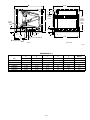
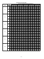
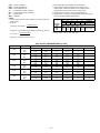
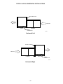
Cased Horizontal
Furnace Coil
CK3B
Sizes A024 thru A060
This horizontal N-Coil is designed to provide the highest
standard of reliability and durability. The CK3B coil casing is
unpainted embossed galvanized steel. The cabinet is fully
insulated to minimize energy loss.
The CK3B is designed for application with horizontal furnaces.
The 2-directional airflow allows for either horizontal-right or
horizontal-left furnace fit-up. This coil is ideally suited for either
attic or crawl space installation.
Our advanced manufacturing methods give a better bond of the
fin and tube. Contaminants are not introduced into coil during
manufacturing. Galvanic action is minimized. The coils are
approved for air conditioning or heat pump application in the
horizontal configuration.
The CK3B coil includes a refrigerant control metering device for
improved serviceability over check valves and expansion
devices used in conventional coils. Sweat-type connections are
furnished for installation of the refrigerant tubes.
The coil is designed to provide improved condensate removal.
The robust condensate pan has brass inserts in the primary and
secondary drain connections and meets FHA requirements.
Form No. PDS CK3B.24.2
MODEL NUMBER NOMENCLATURE
C
K
3
B
X
A
024
C—Coil
024—2 Ton
030—2-1/2 Ton
036—3 Ton
042—3-1/2 Ton
048—4 Ton
060—5 Ton
K—Cased, N-Coil
A—Standard
N—Narrow
W—Wide
X—Max. Cap.
Position
3—Horizontal
5—Upflow/Downflow
A—Painted
B—Embossed
• CERTIFICATION • LISTING
• TESTING • INSPECTION
UNIT
AR
HE
Y
MP
PU
AT
MANUFACTUR
ER
T
IFIED O ARI A
RT
S
C
CE
YING WITH
PL
OM
AIR
CO
Y
NING
ITIO
ND
UNIT
AR
T
IFIED O ARI A
RT
S
C
CE
YING WITH
PL
OM
MANUFACTUR
ER
®
®
A
EQ
RI
UIP M E NT
STA
NDARD
21
A
0
EQ
RI
UIP M E NT
STA
NDARD
24
0
CERTIFICATION APPLIES ONLY WHEN
USED WITH PROPER COMPONENTS
AS LISTED WITH ARI
—2—
®
20 3⁄4″
B
3 15⁄16″
OPTIONAL
DUCT
FILLER
PANEL
E
DUCT
OPENING
TYPICAL
BOTH
ENDS
A
3⁄8 IN.
LIQUID
LINE
2 7⁄8″
3″
3⁄8″
4 3⁄8″
1 1⁄2″
1 1⁄4″
1 11⁄16″
9 1⁄8″
18 7⁄8″
3⁄4 IN. NPT DRAIN
C
D SUCTION LINE
FRONT
RIGHT SIDE
A97521
DIMENSIONS (In.)
A
B
C
D
E
SHIPPING
WEIGHT
UNIT
In.
In.
In.
In.
In.
Lb
CK3BXA024
17-9/16
19-1/16
10-1/16
5/8
16
36.0
CK3BXA030
17-9/16
19-1/16
10-1/16
3/4
16
39.5
CK3BXA036
17-9/16
22-1/16
10-1/4
3/4
16
45.5
CK3BXA042
21-1/16
22-1/16
10-1/4
7/8
19-1/2
47.0
CK3BXA048
21-1/16
22-1/16
10-1/4
7/8
19-1/2
51.0
CK3BXA060
24-9/16
28-1/8
13-3/6
7/8
23
64.0
—3—
COOLING CAPACITIES (MBH)
UNIT
SIZE
CFM
600
A024
800
1000
750
A030
1000
1250
900
A036
1200
1500
1050
A042
1400
1750
1200
A048
1600
2000
1600
A060
SATURATED TEMPERATURE LEAVING EVAPORATOR (°F)
INDOOR COIL
AIR
2000
2400
EWB
72
67
62
72
67
62
72
67
62
72
67
62
72
67
62
72
67
62
72
67
62
72
67
62
72
67
62
72
67
62
72
67
62
72
67
62
72
67
62
72
67
62
72
67
62
72
67
62
72
67
62
72
67
62
30
TC
38.7
32.6
27.0
44.0
37.4
30.6
47.9
40.7
33.7
54.4
45.1
36.0
64.1
53.6
43.4
72.1
59.6
49.0
63.4
52.1
42.8
75.1
61.6
51.1
83.3
69.4
56.6
75.4
62.1
51.5
87.8
72.9
60.0
96.3
80.8
65.7
79.8
66.6
55.2
91.0
76.7
62.7
99.2
84.0
69.0
101.0
83.8
68.7
113.0
94.0
77.0
123.0
103.0
83.0
SHC
17.9
19.5
20.9
20.4
22.8
25.0
22.3
25.5
28.6
25.3
26.5
27.3
29.5
31.8
33.4
33.0
35.8
38.4
29.6
31.0
32.7
34.7
37.2
40.2
38.5
42.5
46.2
35.0
37.3
39.8
40.6
44.4
48.3
44.6
50.1
55.1
36.9
39.8
42.8
42.1
46.9
51.0
46.1
52.6
58.5
46.7
49.9
53.0
52.2
56.8
61.2
56.6
62.8
68.4
35
BF
0.00
0.07
0.05
0.21
0.10
0.07
0.18
0.13
0.10
0.00
0.07
0.05
0.00
0.11
0.10
0.00
0.14
0.14
0.00
0.00
0.00
0.00
0.02
0.02
0.17
0.06
0.04
0.00
0.00
0.01
0.18
0.05
0.03
0.16
0.08
0.07
0.00
0.07
0.06
0.22
0.10
0.08
0.19
0.13
0.11
0.00
0.07
0.07
0.00
0.10
0.09
0.26
0.13
0.11
TC
35.4
29.1
23.4
40.4
33.5
27.0
44.0
36.6
30.0
48.7
39.1
30.5
57.7
46.8
36.9
64.7
52.4
42.0
57.2
46.0
36.7
67.8
54.5
44.0
75.5
61.3
49.3
68.0
55.0
44.2
79.4
64.4
52.0
87.4
71.5
57.6
72.6
59.1
47.6
83.0
68.1
54.9
90.7
74.8
60.8
90.8
73.5
58.2
102.0
82.6
66.0
111.0
89.9
72.2
40
SHC
16.4
17.9
19.2
18.9
21.1
23.2
20.7
23.8
26.7
22.7
23.7
24.5
26.7
28.7
30.3
29.9
32.7
35.2
26.8
28.1
29.6
31.6
34.0
36.7
35.3
38.9
42.5
31.8
34.0
36.2
37.1
40.7
44.3
41.1
46.1
50.9
33.7
36.4
39.1
38.7
43.1
47.2
42.7
48.8
54.3
42.2
45.2
48.0
47.4
51.8
56.0
51.6
57.4
63.0
BF
0.00
0.06
0.05
0.17
0.10
0.08
0.17
0.13
0.11
0.00
0.07
0.06
0.00
0.10
0.10
0.00
0.14
0.13
0.00
0.00
0.00
0.00
0.02
0.03
0.13
0.06
0.06
0.00
0.00
0.01
0.13
0.04
0.05
0.13
0.08
0.08
0.00
0.06
0.06
0.18
0.10
0.09
0.17
0.13
0.12
0.00
0.07
0.07
0.00
0.10
0.10
0.21
0.13
0.12
See notes on page 5.
—4—
TC
32.0
25.6
19.8
36.8
29.5
23.4
40.1
32.4
26.2
43.1
33.2
25.0
51.2
40.1
30.4
57.3
45.3
35.0
50.9
39.8
30.5
60.5
47.5
36.9
67.6
53.1
42.0
60.7
47.8
36.9
71.0
55.9
44.0
78.5
62.2
49.5
65.4
51.7
40.0
75.0
59.5
47.1
82.2
65.7
52.6
80.4
63.1
47.7
90.4
71.2
55.1
98.4
77.3
61.4
SHC
15.0
16.3
17.4
17.3
19.4
21.4
19.2
22.0
24.9
20.1
20.9
21.8
23.9
25.6
27.2
26.8
29.5
32.1
23.9
25.1
26.6
28.5
30.8
33.2
32.1
35.4
38.8
28.6
30.7
32.7
33.6
36.9
40.3
37.5
42.2
46.6
30.6
33.0
35.4
35.4
39.4
43.4
39.4
44.9
50.2
37.6
40.5
43.0
42.6
46.8
50.7
46.7
52.0
57.5
45
BF
0.13
0.06
0.05
0.13
0.09
0.09
0.16
0.12
0.12
0.00
0.06
0.07
0.19
0.10
0.10
0.20
0.13
0.13
0.00
0.00
0.01
0.05
0.02
0.03
0.09
0.05
0.07
0.02
0.00
0.02
0.07
0.04
0.06
0.11
0.08
0.10
0.12
0.06
0.06
0.13
0.09
0.10
0.15
0.12
0.14
0.12
0.06
0.07
0.14
0.09
0.10
0.16
0.12
0.13
TC
28.1
21.5
16.2
32.4
25.0
19.7
35.5
27.3
22.7
36.6
26.7
19.7
43.9
32.3
24.3
49.4
36.8
28.6
44.3
32.8
23.9
52.1
39.3
29.3
58.5
44.4
34.3
52.7
39.3
29.1
61.3
46.7
35.5
67.9
51.9
41.7
57.0
43.2
32.2
65.4
50.1
39.3
72.0
55.1
45.4
69.1
51.1
38.2
77.5
58.5
45.0
84.2
64.3
51.1
SHC
13.3
14.5
15.5
15.6
17.5
19.3
17.4
20.0
22.5
17.3
18.1
19.0
20.9
22.3
24.0
23.7
25.9
28.4
21.0
22.1
23.0
25.1
27.3
28.9
28.5
31.7
34.3
25.3
26.9
28.3
29.8
33.0
35.5
33.5
37.9
41.7
27.1
29.3
31.3
31.7
35.4
39.0
35.5
40.5
45.4
33.0
35.3
37.6
37.5
41.3
44.7
41.2
46.5
51.1
50
BF
0.08
0.05
0.08
0.11
0.08
0.12
0.14
0.11
0.17
0.07
0.05
0.09
0.12
0.09
0.12
0.15
0.13
0.16
0.00
0.00
0.04
0.03
0.02
0.08
0.06
0.05
0.11
0.00
0.01
0.06
0.05
0.04
0.10
0.09
0.08
0.15
0.08
0.05
0.08
0.11
0.09
0.13
0.14
0.12
0.18
0.08
0.06
0.11
0.11
0.10
0.15
0.13
0.12
0.18
TC
23.7
16.6
13.3
27.2
19.7
16.6
30.0
21.9
19.4
29.3
20.0
16.1
35.2
24.1
20.1
40.1
27.5
23.7
36.3
24.9
19.2
43.4
30.2
24.2
48.4
34.5
28.8
43.6
30.2
23.7
51.0
36.1
29.7
55.9
40.9
35.0
47.5
33.3
26.7
54.5
39.4
33.1
60.0
44.0
38.5
56.0
38.0
31.6
63.5
43.7
37.3
69.4
48.3
42.5
SHC
11.6
12.5
13.3
13.7
15.4
16.6
15.4
17.9
19.4
14.5
15.2
16.1
17.6
18.8
20.1
20.3
22.0
23.7
17.9
18.8
19.2
21.8
23.4
24.2
24.8
27.5
28.8
21.7
23.1
23.7
25.9
28.5
29.7
29.1
33.4
35.0
23.4
25.2
26.7
27.6
31.0
33.1
31.2
36.0
38.5
28.0
29.8
31.6
32.3
35.2
37.3
35.8
40.0
42.5
BF
0.07
0.06
0.18
0.10
0.09
0.23
0.13
0.12
0.28
0.06
0.08
0.21
0.10
0.11
0.26
0.14
0.15
0.30
0.00
0.01
0.18
0.02
0.04
0.22
0.06
0.07
0.25
0.00
0.03
0.20
0.05
0.06
0.24
0.09
0.10
0.28
0.07
0.07
0.20
0.10
0.11
0.25
0.13
0.13
0.30
0.07
0.08
0.24
0.10
0.11
0.28
0.13
0.14
0.32
CFM —
EWB —
LWB —
TC —
SHC —
BF —
MBH —
Cubic Ft per Minute
Entering Wet Bulb (°F)
Leaving Wet Bulb (°F)
Total Cooling Capacity 1000 Btuh
Total Sensible Capacity 1000 Btuh
Bypass Factor
1000 Btuh
3. Direct interpolation is permissible. Do not extrapolate.
4. SHC is based on 80°F db temperature of air entering coil.
Below 80°F db, subtract (Correction Factor x CFM) from SHC.
Above 80°F db, add (Correction Factor x CFM) to SHC.
5. All data points are based on 10°F superheat leaving coil.
6. Bypass Factor = 0 indicates no psychometric solution. Use bypass
factor of next lower EWB for approximation.
NOTES:
1. Contact manufacturer for cooling capacities at conditions other than
shown in table.
2. Formulas:
ENTERING AIR DRY BULB TEMPERATURE (°F)
BYPASS
FACTOR
0.10
0.20
0.30
sensible heat cap.
Leaving db = entering db —
1.09 x CFM
Leaving wb = wb corresponding to enthalpy of air leaving coil (hLWB)
total capacity (Btuh)
hLWB = hEWB —
4.5 x CFM
79
78
81
82
0.98
0.87
0.76
1.96
1.74
1.53
77
76
75
83
84
84
Correction Factor
2.94
3.92
4.91
2.62
3.49
4.36
2.29
3.05
3.82
Under 75
Over 85
Use formula
shown below
Interpolation is permissible.
Correction Factor = 1.09 x (1 – BF) x (db – 80)
where hEWB = enthalpy of air entering coil.
COIL STATIC PRESSURE DROP (In. WC)
UNIT SIZE
BULB
AIR QUANTITY (CFM)
600
700
800
900
—
—
0.10
0.08
0.13
0.11
0.16
0.13
—
—
—
—
A024
WET
DRY
0.08
0.06
700
800
900
1000
1100
—
A030
WET
DRY
0.08
0.08
0.12
0.10
0.15
0.14
0.19
0.17
0.23
0.21
—
—
900
1000
1100
1200
1300
—
A036
WET
DRY
0.16
0.13
0.19
0.17
0.23
0.21
0.27
0.25
0.32
0.29
—
—
1000
1100
1200
1300
1400
—
A042
WET
DRY
0.18
0.14
0.21
0.17
0.24
0.20
0.27
0.23
0.31
0.26
—
—
1300
1400
1500
1600
1700
—
A048
WET
DRY
0.19
0.18
0.22
0.21
0.25
0.24
0.28
0.27
0.31
0.30
—
—
1600
1700
1800
1900
2000
2100
A060
WET
DRY
0.19
0.18
0.22
0.20
0.24
0.21
0.26
0.24
0.28
0.26
0.30
0.28
—5—
TYPICAL N-COIL HORIZONTAL INSTALLATIONS
FILLER PLATE
AIRFLOW
N-COIL
FURNACE
DRAIN
CONNECTION
A97203
Horizontal Left
FILLER PLATE
AIRFLOW
FURNACE
N-COIL
DRAIN
CONNECTION
A97037
Horizontal Right
—6—
—7—
SERVICE TRAINING
Packaged Service Training programs are an excellent way to increase your
knowledge of the equipment discussed in this manual, including:
• Unit Familiarization
• Maintenance
• Installation Overview
• Operating Sequence
A large selection of product, theory, and skills programs is available, using popular
video-based formats and materials. All include video and/or slides, plus companion
book.
Classroom Service Training plus "hands-on" the products in our labs can mean
increased confidence that really pays dividends in faster troubleshooting, fewer
callbacks. Course descriptions and schedules are in our catalog.
CALL FOR FREE CATALOG 1-800-962-9212
[ ] Packaged Service Training
[ ] Classroom Service Training
A94328
SPECIFICATIONS SUBJECT TO CHANGE WITHOUT NOTICE
UNIT MUST BE INSTALLED IN ACCORDANCE
WITH INSTALLATION INSTRUCTIONS
Cancels: PDS CK3B.24.1B
© 1997 Bryant Heating & Cooling Systems, 7310 W. Morris St., Indpls., IN 46231
—8—
PRINTED IN U.S.A.
Catalog No. 12CK-3B0
9-97


![MBP-12GUILE/12GUI取扱説明書[PDF:4.9MB]](http://vs1.manualzilla.com/store/data/006623918_2-b495e49e932502c0d2a50795758175dc-150x150.png)
![カタログPDFダウンロード[PDF:1.7MB]](http://vs1.manualzilla.com/store/data/006581727_2-bb010ce40f62d4b878607c76783fb901-150x150.png)