1
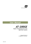
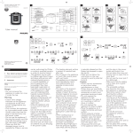
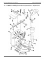
Pcbrm15 & PCBRM System 5.2 User’s Manual
5.5
Chapter 5: Maintenance/Parts
PCBRM System 5.2 – Specific Parts
Note
SEE PCBRM15 FOR A LIST OF COMMON PARTS.
5
6
7
3
4
1
Item
1
2
3
4
5
6
7
*
Part#
PH155
PH161
Proj.DRS.SCS.73
4005.01.111
12365-2
ST350
PH154
PH157
Part No. 4005.00.906
2
Description
Temperature Controller
Circuit Breaker
Handle
Handle Extension
Bearing Block
Flow Well Heater Box (option)
Panel Heater
Panel Heater Thermocouple (not shown)
5-11
Pcbrm15 & PCBRM System 5.2 User’s Manual
5.6
Chapter 5: Maintenance/Parts
PCBRM15 & PCBRM System 5.2 Mechanical Breakdown – Exploded View
28
27
26
25
32
29
22
30
4
7
6
5
8
2
3
23
24
14
18
16
15
17
1
45
44
49
48
49
50
51
57
56
47
55
9
54
20
46
53
52
19
21
10
58
59
33
11
34
35
43
42
41
40
36
39
38
37
Part No. 4005.00.906
13
12
5-12
Pcbrm15 & PCBRM System 5.2 User’s Manual
Chapter 5: Maintenance/Parts
Mechanical Breakdown - Parts List
Description
1.
2.
3.
4.
5.
6.
7.
8.
9.
10.
11.
12.
13.
14.
15.
16.
17.
18.
19.
20.
21.
22.
23.
24.
25.
26.
27.
28.
29.
30.
31.
32.
33.
34.
35.
36.
37.
38.
39.
40.
41.
42.
43.
44.
45.
46.
47.
48.
49.
50.
51.
52.
53.
54.
55.
56.
57.
58.
59.
Solder Pot
Solder Pot Cover
Pump Assembly, only
Motor Assembly
Drive Belt - High Temperature
Belt Guard
Belt Guard Hex Screw
Pump Mounting Screw
Pot Spacer
Thermocouple/Process with fitting
Thermocouple/Override with fitting
Pot Screw
Washer, Pot Screw
Upper Carrier Rail
Lower Carrier Rail
Right Carrier Arm Assembly
Rail Stop
Screw, 6-32 x 3/4, Rail Stop
Adaptor Plate
Adapter Screw
Carrier Attach Screw
Left Carrier Arm Assembly
Heat Shield
Screw, 6-32 x 1/4, Heat Shield
Bracket
Spring
Knob
Washer, #10
Y-Stop Knob
Y-Stop
Carrier Arm, Lock Knob
Arm Attach Screw
E-Stop
Carrier Lock Shaft
Carrier Lock Knob
Z-Crank Assembly
Leveling Legs
Hex Nut, 5/16
Height Adjustment Belt
Drive Rod Gear
Coupling
Gear Box
Pot Shield Knob
Rear Panel
Rear Panel Screw
Temperature Controller
Air Gauge
Flow Potentiometer - 50k
Knob and Dial
Duration Potentiometer - 25k
Power Switch
Reset Switch
Power Light
Cycle Light
Cycle Switch
Mode Switch
Temp Switch/Power
Air Regulator
Drive Shaft
Part No. 4005.00.906
Qty.
1
1
1
1
1
1
2
2
4
1
1
4
4
1
1
1
2
4
1
2
8
1
1
3
1
1
1
1
1
1
2
4
1
1
1
1
4
1
1
1
1
1
2
1
8
1
1
1
2
1
1
1
1
1
1
1
1
1
1
Part Number
12510
2004.01.108
2004.01.040
12420
12467
12461
59A
23A
12511
12801
12802
21A
33A
12365
12366
12305
12315
6B
12325
22A
30A
12304
12322
1A
12316
12374
12319-1
53A
0100.03.046
12326
12306
29B
12837
12320
12356
12CK
12151
36A
12CK6
12353
12362
12358
12308
12812
13B
12860
12757
9002.05.018
9002.18.001
9002.05.017
12856
12853-2
12877-Z
12876
12854
12855
12856
9001.12.006
12359
5-13
Pcbrm15 & PCBRM System 5.2 User’s Manual
5.3
Chapter 5: Maintenance/Parts
Pump Disassembly & Cleaning
CAUTION
SOLDER WILL BE HOT
7. Remove Pump Baffle (P) using needle nose pliers while pump is in the pot with solder.
8. Remove solder from pot using ladle supplied with unit.
Note
ALLOW MACHINE TO COOL BEFORE REMOVING PUMP FROM POT.
9. Remove two screws holding pulley guard to pump.
10. Remove two screws holding pump to pot.
11. Remove two screws holding pump housing (B) to pump bracket (A) and remove housing (B).
Note
DO NOT LOOSEN OR REMOVE THE FOUR LEVELING NUTS
PUMP WILL NEED TO BE RE-LEVELED UPON INSTALLATION.
(L) AND SET SCREWS (M) OR THE
12. Loosen the two set screws on the pump pulley (G).
13. Remove the two bearing retaining screws (H) and washer (I).
14. Slide the pump shaft (D) with impeller (C) out of the pump bracket (A). Pump sleeve (N) will
drop away at this point.
15. Remove pump bearings (E), spacer (F) and pulley (G) from pump bracket (A).
Note
INSPECT BEARINGS FOR SMOOTH MOVEMENT. REPLACE IF NECESSARY.
16. Remove pump shaft (D) from impeller (C) and discard.
17. Remove pump sleeve insert (R) and discard.
18. Clean all parts of solder and dirt using a wire brush or a tool to scrape solder from pieces.
19. Re-assemble pump as shown in drawing as follows:
• Insert lower bearing into pump bracket.
• Turn bracket upside down and insert pulley (hub side) into upper bearing hole.
• Place spacer on top of pulley.
• Insert shaft into bracket, through pump sleeve, bearing spacer and pulley.
• Turn bracket over and insert upper bearing.
• Install bearing retaining screws (H) and (I).
• Tighten pulley set screws.
• Install impeller onto shaft – before tightening the set screw be certain the play from the
shaft and bearings will not cause impeller to hit pump bracket face. Allow for this
clearance before tightening set screw.
• Spin shaft with fingers and check for any interference. Correct as required.
• Install pump housing (B) to bracket (A). Be certain the index marks are aligned exactly
before tightening. If they are not, the pump will not be level.
• Spin shaft with fingers and check for any interference between impeller and housing.
20. Pump is now ready for installation back into pot. Use anti-seize on the mounting screws when
installing. Alternate tightening screws until snug. DO NOT OVERTIGHTEN. Over-tightening
could cause pump to become un-level.
21. Check level of pump to carrier arms. Re-level if required.
Part No. 4005.00.906
5-5
Pcbrm15 & PCBRM System 5.2 User’s Manual
H
Chapter 5: Maintenance/Parts
I
E
HUB
This side
G
upper
F
E
H
M
I
L
A
J
P
Index Mark
N
D
.
See note 1
9000.02.000
R
O
See note 1
C
NOTE 1:
When cleaning of pump is required, the pump shaft (D) and the
pump sleeve insert (R) need to be replaced.
Index Mark
K
B
Item
Description
Qty.
Part# (PCBRM15)
-
Pump Assembly-PCBRM15
1
2004.01.044
A
B
C
D
E
F
G
H
I
J
K
L
M
N
O
P
Q
R
Pump Bracket
Pump Housing
Pump Impeller
Shaft
Bearing
Spacer
Pulley
Screw, 6-32 x 1/4 Button Hd
Washer, #6 SAE
Screw, 10-32 x 5/8
Nut, 10-32
Nut, 6-32 x
Set Screw, 6-32 x 5/16
Pump Sleeve Assembly
Set Screw, 10-32 x 3/8
Baffle Assembly
Pump Mounting screws (10-32 x _)
Pump Insert
1
1
1
1
2
1
1
2
2
2
2
4
4
1
1
1
2
1
2004.01.102 (gray iron)
2004.01.101 (gray iron)
2004.01.100 (gray iron)
2004.01.103 (titanium)
9001.09.020
12464
12453
60A
9A
9000.00.000 (titanium)
9000.06.002 (titanium)
8B
11A
2004.01.041 (titanium)
9000.10.249 (titanium)
2004.01.043 (titanium)
23A
12418
Part No. 4005.00.906
5-6


![カタログPDFダウンロード[PDF:1.7MB]](http://vs1.manualzilla.com/store/data/006581727_2-bb010ce40f62d4b878607c76783fb901-150x150.png)


![MBP-12GUILE/12GUI取扱説明書[PDF:4.9MB]](http://vs1.manualzilla.com/store/data/006623918_2-b495e49e932502c0d2a50795758175dc-150x150.png)