1
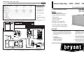
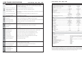
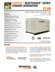
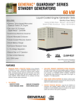
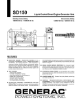
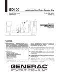
Home Standby - 7kW - 12kW - 15kW Home Standby - 7kW - 12kW - 15kW TRANSFER SWITCH & EMERGENCY LOAD CENTER Model ASPAS1BBA007 Model ASPAS1BBA012 Model ASPAS1BBA015 (7kW) (12kW) (15kW) Transfer Switch Features • Electrically operated, mechanically-held contacts for fast, positive connections. No. of Poles 2 2 2 Current Rating (amps) ......................................................100 ..........................................100 ......................................... 100 Voltage Rating (VAC) ....................................................... 250 ......................................... 250 ......................................... 250 Utility Voltage Monitor (fixed) -Pick-up ........................................................................... 70% ........................................ 70% ....................................... 70% -Dropout ......................................................................... 60% ....................................... 60% ....................................... 60% Return to Utility ....................................................... approx. 13 sec .......................approx. 13 sec. ....................... approx. 13 sec. Exerciser weekly for 12 minutes .................................. Standard .................................Standard .................................Standard UL Listed ...................................................................... Standard .................................Standard .................................Standard Dimensions (H” x W” x D”) .......................................26.5 x 12.5 x 7 ...................... 26.5 x 12.5 x 7 ....................... 26.5 x 12.5 x 7 Total of Pre-wired Circuits .................................................. 8 ............................................ 10 ...........................................12 No. 15A 120V .......................................................... 5 ............................................ 3 ........................................... 5 No. 20A 120V .......................................................... 1 ............................................ 3 ........................................... 3 No. 15A 240V .......................................................... - ............................................ - ........................................... No. 20A 240V .......................................................... - ............................................ 1 ........................................... 1 No. 30A 240V .......................................................... 1 ............................................ 1 ........................................... 1 Circuit Breaker Protected Available RMS Symmetrical Fault Current @ 250 Volts ...................................10,000 .....................................10,000 ......................................10,000 Mechanical Dimensions (in inches) Current No. of Height Rating Poles H1 H2 100 UL Listed 2 26.5 29.25 W2 W1 H1 H2 • Rated for all classes of load, 100% equipment rated, both inductive and resistive. Air-Cooled Gas Engine Generator Sets Continuous Standby Power Rating • 160 millisecond transfer time. INCLUDES: • Automatic Transfer Switch with Built-In Emergency Load Center • Dual coil design. • Pre-wired External Connection Box • Main contacts are silver plated or silver alloy to resist welding and sticking. • Flexible Fuel Line • NEMA 1 enclosure is standard on the 100 amp switch. • Pre-wired conduits • 2 pole, 250 VAC contactors. Model ASPAS1BBA007 - 7kW 60Hz Model ASPAS1BBA012 - 12kW 60Hz Model ASPAS1BBA015 - 15kW 60Hz • Composite Mounting Pad • Natural Gas or LP Gas Operation Width W1 W2 8.14 12.5 Depth • GFCI duplex outlet & 12Vdc outlet 7 Terminal Wire Ranges ATS Rated Amps Switch Terminal 100A 2-Pole UL 1 x 1/0-12 • UL Listed to Canadian safety standards Neutral Lug/Stud 1 x 3/8-16 Stud Ground Lug 1 x 2/0-14 • 2 Year Limited Parts and Labor Warranty FEATURES INNOVATIVE DESIGN & PROTOTYPE TESTING are key components of BRYANT’s success in “IMPROVING POWER BY DESIGN.” But it doesn’t stop there. Total commitment to component testing, reliability testing, environmental testing, destruction and life testing, plus testing to applicable CSA, NEMA, EGSA, and other standards, allows you to choose BRYANT with the confidence that these systems will provide superior performance. TEST CRITERIA: > PROTOTYPE TESTED SOLID-STATE, FREQUENCY COMPENSATED VOLTAGE REGULATION. This state-of-the-art power maximizing regulation system is standard on all BRYANT models. It provides optimized FAST RESPONSE to changing load conditions and MAXIMUM MOTOR STARTING CAPABILITY by electronically torque-matching the surge loads to the engine. SINGLE SOURCE SERVICE RESPONSE from BRYANT’s dealer network provides parts and service know-how for the entire unit, from the engine to the smallest electronic component. You are never on your own when you own a BRYANT system. BRYANT TRANSFER SWITCHES. Long life and reliability are synonymous with BRYANT systems. One reason for this confidence is that the BRYANT product line includes its own transfer systems and controls for total system compatibility. > SYSTEM TORSIONAL TESTED > NEMA MG1-22 EVALUATION > MOTOR STARTING ABILITY BRYANT, INC. • 7310 WEST MORRIS STREET • INDIANAPOLIS, IN 46231 • www.bryant.com Printed in USA 10.05 CATALOG NO. SS-ASPAS07-02 All specifications are subject to change without notice. HOME STANDBY SPECIFICATIONS INSTALLATION SYSTEM UNIT MICROPROCESSOR CONTROL TRANSFER SWITCH GENERATOR ENGINE • Durable (OHVI) Design Home Standby - 7kW - 12kW - 15kW Maximizes engine “breathing” for increased fuel efficiency. Cylinder walls run cooler, reducing oil consumption. Because heat is the primary cause of engine wear, the OHVI has a significantly longer life than competitive engines. • ”Spiny-lok” cast iron cylinder walls Rigid construction and added durability provide long engine life. • Electronic ignition, spark advance and compression release These features combine to assure smooth, quick starting every time. • Full pressure lubrication system Superior lubrication to all vital bearings means better performance, less maintenance and significantly longer engine life. • Low oil pressure shutdown system Superior shutdown protection prevents catastrophic engine damage due to low oil. • High temperature shutdown Prevents damage due to overheating. • Revolving field Allows for smaller, light weight unit that operates 25% more efficiently than a revolving armature generator. • Skewed stator Produces a smooth output waveform for compatibility with electronic equipment. Home Standby - 7kW - 12kW - 15kW GENERATOR Maximizes motor starting capability. Provides more surge capability than brushless generator designs. • Automatic voltage regulation Regulates the output voltage to ±2% prevents damaging voltage spikes. • UL 2200 Listed For your safety • Fully Automatic Transfers your vital electrical loads to the energized source of power. • Remote Mounting Mounts near your existing distribution panel for simple, low cost installation. • UL Listed For your safety • Manual/Auto/Off switch Selects the operating mode. • Utility voltage sensing Constantly monitors utility voltage, setpoints 60% dropout, 80% pick-up, of standard voltage. • Utility interrupt delay Prevents nuisance start-ups of the engine, set point approximately 15 seconds. • Engine warm-up Ensures engine is ready to assume the load, set point approximately 10 seconds. • Engine cool-down Allows engine to cool prior to shutdown, setpoint approximately 1 minute. • Seven day exerciser Operates engine to prevent oil seal drying and damage between power outages. • Timed Trickle Battery charger Maintains battery amperage to insure starting. • Main Line Circuit Breaker Protects generator from overload. • Weather protective enclosure Ensures protection against mother nature. Hinged key locking roof panel for security. Electrostatically applied epoxy paint for durability. • Enclosed critical grade muffler Quiet, critical grade muffler is mounted inside the unit to prevent injuries. • Small, compact, attractive Makes for an easy, eye appealing installation. • Pre-wired External Connection Box Easy Installation - Virtually all hardware included, plus step-by-step photographed Installation Guide. • 1’ Flexible Fuel Line • Composite Mounting Pad • Pre-wired conduits • UL Listed wire nuts Model ASPAS1BBA012 (12kW) Model ASPAS1BBA015 (15kW) Rated Maximum Continuous Power Capacity (LP)................................... 7,000 Watts* . . . . . . . . . . . . . . . . . . .12,000 Watts* . . . . . . . . . . . . . . . . . . .15,000 Watts* Rated Maximum Continuous Power Capacity (NG)...................................6,000 Watts* . . . . . . . . . . . . . . . . . . . .12,000 Watts* . . . . . . . . . . . . . . . . . . .13,000 Watts* Rated Voltage................................................................................................120/240 . . . . . . . . . . . . . . . . . . . . . . . .120/240 . . . . . . . . . . . . . . . . . . . . . . . .120/240 Rated Maximum Continuous Load Current 120 Volts ................................................................................................ 50.0 NG/58.3 LP . . . . . . . . . . . . . . . 100.0 NG/100.0 LP . . . . . . . . . . . . . . .108.3 NG/125.0 LP 240 Volts ................................................................................................ 25.0 NG/29.2 LP . . . . . . . . . . . . . . . .50.0 NG/ 50.0 LP . . . . . . . . . . . . . . . . .54.2 NG/62.5 LP Main Line Circuit Breaker ............................................................................. 30 Amp . . . . . . . . . . . . . . . . . . . . . . . .50 Amp . . . . . . . . . . . . . . . . . . . . . . . .65 Amp Phase ................................................................................................................ .1 . . . . . . . . . . . . . . . . . . . . . . . . . . . .1 . . . . . . . . . . . . . . . . . . . . . . . . . . . . . .1 Number of Rotor Poles .......................................................................................2 . . . . . . . . . . . . . . . . . . . . . . . . . . . . .2 . . . . . . . . . . . . . . . . . . . . . . . . . . . . . .2 Rated AC Frequency ........................................................................................60Hz . . . . . . . . . . . . . . . . . . . . . . . . . .60Hz . . . . . . . . . . . . . . . . . . . . . . . . . .60Hz Power Factor .......................................................................................................1 . . . . . . . . . . . . . . . . . . . . . . . . . . . . .1 . . . . . . . . . . . . . . . . . . . . . . . . . . . . . .1 Battery Requirement (not included) ..........................................................Group 26 . . . . . . . . . . . . . . . . . . . . . . . .Group 26 . . . . . . . . . . . . . . . . . . . . . . .Group 26 12 Volts and . . . . . . . . . . . . . . . . . . . .12 Volts and . . . . . . . . . . . . . . . . . . . . .12 Volts and 350 Cold-cranking . . . . . . . . . . . . . . .525 Cold-cranking . . . . . . . . . . . . . . . .525 Cold-cranking Amperes Minimum . . . . . . . . . . . . . . .Amperes Minimum . . . . . . . . . . . . . . . .Amperes Minimum Shipping Weight (lbs.) (Includes Transfer Switch) .......................................375 . . . . . . . . . . . . . . . . . . . . . . . . . . . . . .470 . . . . . . . . . . . . . . . . . . . . . . . . . . . .487 Dimensions (L” x W” x H”)....................................................................... 48 x 24 x 28-1/4 . . . . . . . . . . . . . . . . .48 x 24 x 28-1/4 . . . . . . . . . . . . . . . . . .48 x 24 x 28-1/4 J ENGINE • Displaced phase excitation Model ASPAS1BBA007 (7kW) Model ASPAS1BBA007 (7kW) Model ASPAS1BBA012 (12kW) Model ASPAS1BBA015 (15kW) Type of Engine .................................................................................................OHVI . . . . . . . . . . . . . . . . . . . . . . .OHVI V-TWIN . . . . . . . . . . . . . . . . . . . .OHVI V-TWIN Number of Cylinders............................................................................................1 . . . . . . . . . . . . . . . . . . . . . . . . . . . . . .2 . . . . . . . . . . . . . . . . . . . . . . . . . . . . . .2 Rated Horsepower................................................................................. 14.5 @ 3,600 rpm . . . . . . . . . . . . . . . . .30 @ 3,600 rpm . . . . . . . . . . . . . . . . . .30 @ 3,600 rpm Displacement................................................................................................... 410cc . . . . . . . . . . . . . . . . . . . . . . . . . .992cc . . . . . . . . . . . . . . . . . . . . . . . . . .992cc Cylinder Block.........................................................................................Aluminum w/Cast . . . . . . . . . . . . . . . . .Aluminum w/Cast . . . . . . . . . . . . . . . . .Aluminum w/Cast Iron Sleeve . . . . . . . . . . . . . . . . . . . . . .Iron Sleeve . . . . . . . . . . . . . . . . . . . . . .Iron Sleeve Valve Arrangement...................................................................................Overhead Valve . . . . . . . . . . . . . . . . . .Overhead Valve . . . . . . . . . . . . . . . . . .Overhead Valve Ignition System.................................................................................. .Solid-state w/Magneto . . . . . . . . . . . . .Solid-state w/Magneto . . . . . . . . . . . . .Solid-state w/Magneto Compression Ratio.......................................................................................... .8.6:1 . . . . . . . . . . . . . . . . . . . . . . . . . . .9.5:1 . . . . . . . . . . . . . . . . . . . . . . . . . . .9.5:1 Starter............................................................................................................ .12 Vdc . . . . . . . . . . . . . . . . . . . . . . . . .12 Vdc . . . . . . . . . . . . . . . . . . . . . . . . . .12Vdc Oil Capacity Including Filter..................................................................... Approx. 1.5 Qts . . . . . . . . . . . . . . . . . .Approx. 1.7 Qts. . . . . . . . . . . . . . . . . . .Approx. 1.7 Qts. Operating RPM............................................................................................... .3,600 . . . . . . . . . . . . . . . . . . . . . . . . . .3,600 . . . . . . . . . . . . . . . . . . . . . . . . . .3,600 Fuel Consumption Natural Gas cu.ft./hr. 1/2 Load . . . . . . . . . . . . . . . . . . . . . . . . . . . . . . . . . . . . . . . . . . . . . . . . . .66 . . . . . . . . . . . . . . . . . . . . . . . . . . . .152 . . . . . . . . . . . . . . . . . . . . . . . . . . . .156 Full Load . . . . . . . . . . . . . . . . . . . . . . . . . . . . . . . . . . . . . . . . . . . . . . . . .119 . . . . . . . . . . . . . . . . . . . . . . . . . . .215 . . . . . . . . . . . . . . . . . . . . . . . . . . . .220 Liquid Propane ft3/hr(gal/hr) 1/2 Load . . . . . . . . . . . . . . . . . . . . . . . . . . . . . . . . . . . . . . . . . . . . . . . .30(0.82) . . . . . . . . . . . . . . . . . . . . . . .56(1.53) . . . . . . . . . . . . . . . . . . . . . . . .58(1.58) Full Load . . . . . . . . . . . . . . . . . . . . . . . . . . . . . . . . . . . . . . . . . . . . . . .54(1.47) . . . . . . . . . . . . . . . . . . . . . . .76(2.08) . . . . . . . . . . . . . . . . . . . . . . . .88(2.40) Required fuel pressure to generator fuel inlet at all load ranges - 5 to 7 inches of water column for natural gas, 11 to 14 inches of water column for LP gas CONTROLS Model Switch - AutoAutomatic Start on Utility failure/7 day exerciser - Off. . . . . . . . . . . . . . . . . . . . . . . . . . . . . . . . . . . . . . . . . . . . . . . . . . . . . . . . . . . Stops unit. Power is removed control and charger still operate - Manual/Test (start) . . . . . . . . . . . . . . . . . . . . . . . . . . . . . . . . . . . . . . . . . . . . . . Start with starter control, unit stays on. If utility fails, transfer to load takes place. Engine Start Sequence. . . . . . . . . . . . . . . . . . . . . . . . . . . . . . . . . . . . . . . . . . . . Cyclic cranking: 7 sec. on, 7 rest (90 sec. maximum duration) Engine Warm-up . . . . . . . . . . . . . . . . . . . . . . . . . . . . . . . . . . . . . . . . . . . . . . . . . 10 seconds Engine Cool-Down . . . . . . . . . . . . . . . . . . . . . . . . . . . . . . . . . . . . . . . . . . . . . . . 1 minute Starter Lock-out . . . . . . . . . . . . . . . . . . . . . . . . . . . . . . . . . . . . . . . . . . . . . . . . . Starter cannot re-engage until 5 sec. after engine has stopped. 2.5 Amp Timed Trickle Battery Charger. . . . . . . . . . . . . . . . . . . . . . . . . . . . . . . Standard Automatic Voltage Regulator w/Overvoltage Protection . . . . . . . . . . . . . . . . . . . Standard Automatic Low Oil Pressure Shutdown . . . . . . . . . . . . . . . . . . . . . . . . . . . . . . . Standard Overspeed Shutdown . . . . . . . . . . . . . . . . . . . . . . . . . . . . . . . . . . . . . . . . . . . . . Standard, 72Hz High Temperature Shutdown . . . . . . . . . . . . . . . . . . . . . . . . . . . . . . . . . . . . . . . Standard Overcrank Protection . . . . . . . . . . . . . . . . . . . . . . . . . . . . . . . . . . . . . . . . . . . . . Standard Safety Fuse. . . . . . . . . . . . . . . . . . . . . . . . . . . . . . . . . . . . . . . . . . . . . . . . . . . . . Standard Rating definitions - Standby: Applicable for supplying emergency power for the duration of the utility power outage. No overload capability is available for this rating. (All ratings in accordance with BS5514, ISO3046 and DIN6271). Prime (Unlimited Running Time): Unit not recommended for prime power applications. Applicable for supplying electric power in lieu of commercially purchased power. Prime power is the maximum power available at variable load. A 10% overload capacity is available for 1 hour in 12 hours. (All ratings in accordance with BS5514, ISO3046, ISO8528 and DIN6271). * Maximum wattage and current are subject to and limited by such factors as fuel Btu content, ambient temperature, altitude, engine power and condition, etc. Maximum power decreases about 3.5 percent for each 1,000 feet above sea level; and also will decrease about 1 percent for each 12° C (10° F) above 15.5° C (60°F). Home Standby - 7kW - 12kW - 15kW Home Standby - 7kW - 12kW - 15kW TRANSFER SWITCH & EMERGENCY LOAD CENTER Model ASPAS1BBA007 Model ASPAS1BBA012 Model ASPAS1BBA015 (7kW) (12kW) (15kW) Transfer Switch Features • Electrically operated, mechanically-held contacts for fast, positive connections. No. of Poles 2 2 2 Current Rating (amps) ......................................................100 ..........................................100 ......................................... 100 Voltage Rating (VAC) ....................................................... 250 ......................................... 250 ......................................... 250 Utility Voltage Monitor (fixed) -Pick-up ........................................................................... 70% ........................................ 70% ....................................... 70% -Dropout ......................................................................... 60% ....................................... 60% ....................................... 60% Return to Utility ....................................................... approx. 13 sec .......................approx. 13 sec. ....................... approx. 13 sec. Exerciser weekly for 12 minutes .................................. Standard .................................Standard .................................Standard UL Listed ...................................................................... Standard .................................Standard .................................Standard Dimensions (H” x W” x D”) .......................................26.5 x 12.5 x 7 ...................... 26.5 x 12.5 x 7 ....................... 26.5 x 12.5 x 7 Total of Pre-wired Circuits .................................................. 8 ............................................ 10 ...........................................12 No. 15A 120V .......................................................... 5 ............................................ 3 ........................................... 5 No. 20A 120V .......................................................... 1 ............................................ 3 ........................................... 3 No. 15A 240V .......................................................... - ............................................ - ........................................... No. 20A 240V .......................................................... - ............................................ 1 ........................................... 1 No. 30A 240V .......................................................... 1 ............................................ 1 ........................................... 1 Circuit Breaker Protected Available RMS Symmetrical Fault Current @ 250 Volts ...................................10,000 .....................................10,000 ......................................10,000 Mechanical Dimensions (in inches) Current No. of Height Rating Poles H1 H2 100 UL Listed 2 26.5 29.25 W2 W1 H1 H2 • Rated for all classes of load, 100% equipment rated, both inductive and resistive. Air-Cooled Gas Engine Generator Sets Continuous Standby Power Rating • 160 millisecond transfer time. INCLUDES: • Automatic Transfer Switch with Built-In Emergency Load Center • Dual coil design. • Pre-wired External Connection Box • Main contacts are silver plated or silver alloy to resist welding and sticking. • Flexible Fuel Line • NEMA 1 enclosure is standard on the 100 amp switch. • Pre-wired conduits • 2 pole, 250 VAC contactors. Model ASPAS1BBA007 - 7kW 60Hz Model ASPAS1BBA012 - 12kW 60Hz Model ASPAS1BBA015 - 15kW 60Hz • Composite Mounting Pad • Natural Gas or LP Gas Operation Width W1 W2 8.14 12.5 Depth • GFCI duplex outlet & 12Vdc outlet 7 Terminal Wire Ranges ATS Rated Amps Switch Terminal 100A 2-Pole UL 1 x 1/0-12 • UL Listed to Canadian safety standards Neutral Lug/Stud 1 x 3/8-16 Stud Ground Lug 1 x 2/0-14 • 2 Year Limited Parts and Labor Warranty FEATURES INNOVATIVE DESIGN & PROTOTYPE TESTING are key components of BRYANT’s success in “IMPROVING POWER BY DESIGN.” But it doesn’t stop there. Total commitment to component testing, reliability testing, environmental testing, destruction and life testing, plus testing to applicable CSA, NEMA, EGSA, and other standards, allows you to choose BRYANT with the confidence that these systems will provide superior performance. TEST CRITERIA: > PROTOTYPE TESTED SOLID-STATE, FREQUENCY COMPENSATED VOLTAGE REGULATION. This state-of-the-art power maximizing regulation system is standard on all BRYANT models. It provides optimized FAST RESPONSE to changing load conditions and MAXIMUM MOTOR STARTING CAPABILITY by electronically torque-matching the surge loads to the engine. SINGLE SOURCE SERVICE RESPONSE from BRYANT’s dealer network provides parts and service know-how for the entire unit, from the engine to the smallest electronic component. You are never on your own when you own a BRYANT system. BRYANT TRANSFER SWITCHES. Long life and reliability are synonymous with BRYANT systems. One reason for this confidence is that the BRYANT product line includes its own transfer systems and controls for total system compatibility. > SYSTEM TORSIONAL TESTED > NEMA MG1-22 EVALUATION > MOTOR STARTING ABILITY BRYANT, INC. • 7310 WEST MORRIS STREET • INDIANAPOLIS, IN 46231 • www.bryant.com Printed in USA 10.05 CATALOG NO. SS-ASPAS07-02 All specifications are subject to change without notice. HOME STANDBY SPECIFICATIONS INSTALLATION SYSTEM UNIT MICROPROCESSOR CONTROL TRANSFER SWITCH GENERATOR ENGINE • Durable (OHVI) Design Home Standby - 7kW - 12kW - 15kW Maximizes engine “breathing” for increased fuel efficiency. Cylinder walls run cooler, reducing oil consumption. Because heat is the primary cause of engine wear, the OHVI has a significantly longer life than competitive engines. • ”Spiny-lok” cast iron cylinder walls Rigid construction and added durability provide long engine life. • Electronic ignition, spark advance and compression release These features combine to assure smooth, quick starting every time. • Full pressure lubrication system Superior lubrication to all vital bearings means better performance, less maintenance and significantly longer engine life. • Low oil pressure shutdown system Superior shutdown protection prevents catastrophic engine damage due to low oil. • High temperature shutdown Prevents damage due to overheating. • Revolving field Allows for smaller, light weight unit that operates 25% more efficiently than a revolving armature generator. • Skewed stator Produces a smooth output waveform for compatibility with electronic equipment. Home Standby - 7kW - 12kW - 15kW GENERATOR Maximizes motor starting capability. Provides more surge capability than brushless generator designs. • Automatic voltage regulation Regulates the output voltage to ±2% prevents damaging voltage spikes. • UL 2200 Listed For your safety • Fully Automatic Transfers your vital electrical loads to the energized source of power. • Remote Mounting Mounts near your existing distribution panel for simple, low cost installation. • UL Listed For your safety • Manual/Auto/Off switch Selects the operating mode. • Utility voltage sensing Constantly monitors utility voltage, setpoints 60% dropout, 80% pick-up, of standard voltage. • Utility interrupt delay Prevents nuisance start-ups of the engine, set point approximately 15 seconds. • Engine warm-up Ensures engine is ready to assume the load, set point approximately 10 seconds. • Engine cool-down Allows engine to cool prior to shutdown, setpoint approximately 1 minute. • Seven day exerciser Operates engine to prevent oil seal drying and damage between power outages. • Timed Trickle Battery charger Maintains battery amperage to insure starting. • Main Line Circuit Breaker Protects generator from overload. • Weather protective enclosure Ensures protection against mother nature. Hinged key locking roof panel for security. Electrostatically applied epoxy paint for durability. • Enclosed critical grade muffler Quiet, critical grade muffler is mounted inside the unit to prevent injuries. • Small, compact, attractive Makes for an easy, eye appealing installation. • Pre-wired External Connection Box Easy Installation - Virtually all hardware included, plus step-by-step photographed Installation Guide. • 1’ Flexible Fuel Line • Composite Mounting Pad • Pre-wired conduits • UL Listed wire nuts Model ASPAS1BBA012 (12kW) Model ASPAS1BBA015 (15kW) Rated Maximum Continuous Power Capacity (LP)................................... 7,000 Watts* . . . . . . . . . . . . . . . . . . .12,000 Watts* . . . . . . . . . . . . . . . . . . .15,000 Watts* Rated Maximum Continuous Power Capacity (NG)...................................6,000 Watts* . . . . . . . . . . . . . . . . . . . .12,000 Watts* . . . . . . . . . . . . . . . . . . .13,000 Watts* Rated Voltage................................................................................................120/240 . . . . . . . . . . . . . . . . . . . . . . . .120/240 . . . . . . . . . . . . . . . . . . . . . . . .120/240 Rated Maximum Continuous Load Current 120 Volts ................................................................................................ 50.0 NG/58.3 LP . . . . . . . . . . . . . . . 100.0 NG/100.0 LP . . . . . . . . . . . . . . .108.3 NG/125.0 LP 240 Volts ................................................................................................ 25.0 NG/29.2 LP . . . . . . . . . . . . . . . .50.0 NG/ 50.0 LP . . . . . . . . . . . . . . . . .54.2 NG/62.5 LP Main Line Circuit Breaker ............................................................................. 30 Amp . . . . . . . . . . . . . . . . . . . . . . . .50 Amp . . . . . . . . . . . . . . . . . . . . . . . .65 Amp Phase ................................................................................................................ .1 . . . . . . . . . . . . . . . . . . . . . . . . . . . .1 . . . . . . . . . . . . . . . . . . . . . . . . . . . . . .1 Number of Rotor Poles .......................................................................................2 . . . . . . . . . . . . . . . . . . . . . . . . . . . . .2 . . . . . . . . . . . . . . . . . . . . . . . . . . . . . .2 Rated AC Frequency ........................................................................................60Hz . . . . . . . . . . . . . . . . . . . . . . . . . .60Hz . . . . . . . . . . . . . . . . . . . . . . . . . .60Hz Power Factor .......................................................................................................1 . . . . . . . . . . . . . . . . . . . . . . . . . . . . .1 . . . . . . . . . . . . . . . . . . . . . . . . . . . . . .1 Battery Requirement (not included) ..........................................................Group 26 . . . . . . . . . . . . . . . . . . . . . . . .Group 26 . . . . . . . . . . . . . . . . . . . . . . .Group 26 12 Volts and . . . . . . . . . . . . . . . . . . . .12 Volts and . . . . . . . . . . . . . . . . . . . . .12 Volts and 350 Cold-cranking . . . . . . . . . . . . . . .525 Cold-cranking . . . . . . . . . . . . . . . .525 Cold-cranking Amperes Minimum . . . . . . . . . . . . . . .Amperes Minimum . . . . . . . . . . . . . . . .Amperes Minimum Shipping Weight (lbs.) (Includes Transfer Switch) .......................................375 . . . . . . . . . . . . . . . . . . . . . . . . . . . . . .470 . . . . . . . . . . . . . . . . . . . . . . . . . . . .487 Dimensions (L” x W” x H”)....................................................................... 48 x 24 x 28-1/4 . . . . . . . . . . . . . . . . .48 x 24 x 28-1/4 . . . . . . . . . . . . . . . . . .48 x 24 x 28-1/4 J ENGINE • Displaced phase excitation Model ASPAS1BBA007 (7kW) Model ASPAS1BBA007 (7kW) Model ASPAS1BBA012 (12kW) Model ASPAS1BBA015 (15kW) Type of Engine .................................................................................................OHVI . . . . . . . . . . . . . . . . . . . . . . .OHVI V-TWIN . . . . . . . . . . . . . . . . . . . .OHVI V-TWIN Number of Cylinders............................................................................................1 . . . . . . . . . . . . . . . . . . . . . . . . . . . . . .2 . . . . . . . . . . . . . . . . . . . . . . . . . . . . . .2 Rated Horsepower................................................................................. 14.5 @ 3,600 rpm . . . . . . . . . . . . . . . . .30 @ 3,600 rpm . . . . . . . . . . . . . . . . . .30 @ 3,600 rpm Displacement................................................................................................... 410cc . . . . . . . . . . . . . . . . . . . . . . . . . .992cc . . . . . . . . . . . . . . . . . . . . . . . . . .992cc Cylinder Block.........................................................................................Aluminum w/Cast . . . . . . . . . . . . . . . . .Aluminum w/Cast . . . . . . . . . . . . . . . . .Aluminum w/Cast Iron Sleeve . . . . . . . . . . . . . . . . . . . . . .Iron Sleeve . . . . . . . . . . . . . . . . . . . . . .Iron Sleeve Valve Arrangement...................................................................................Overhead Valve . . . . . . . . . . . . . . . . . .Overhead Valve . . . . . . . . . . . . . . . . . .Overhead Valve Ignition System.................................................................................. .Solid-state w/Magneto . . . . . . . . . . . . .Solid-state w/Magneto . . . . . . . . . . . . .Solid-state w/Magneto Compression Ratio.......................................................................................... .8.6:1 . . . . . . . . . . . . . . . . . . . . . . . . . . .9.5:1 . . . . . . . . . . . . . . . . . . . . . . . . . . .9.5:1 Starter............................................................................................................ .12 Vdc . . . . . . . . . . . . . . . . . . . . . . . . .12 Vdc . . . . . . . . . . . . . . . . . . . . . . . . . .12Vdc Oil Capacity Including Filter..................................................................... Approx. 1.5 Qts . . . . . . . . . . . . . . . . . .Approx. 1.7 Qts. . . . . . . . . . . . . . . . . . .Approx. 1.7 Qts. Operating RPM............................................................................................... .3,600 . . . . . . . . . . . . . . . . . . . . . . . . . .3,600 . . . . . . . . . . . . . . . . . . . . . . . . . .3,600 Fuel Consumption Natural Gas cu.ft./hr. 1/2 Load . . . . . . . . . . . . . . . . . . . . . . . . . . . . . . . . . . . . . . . . . . . . . . . . . .66 . . . . . . . . . . . . . . . . . . . . . . . . . . . .152 . . . . . . . . . . . . . . . . . . . . . . . . . . . .156 Full Load . . . . . . . . . . . . . . . . . . . . . . . . . . . . . . . . . . . . . . . . . . . . . . . . .119 . . . . . . . . . . . . . . . . . . . . . . . . . . .215 . . . . . . . . . . . . . . . . . . . . . . . . . . . .220 Liquid Propane ft3/hr(gal/hr) 1/2 Load . . . . . . . . . . . . . . . . . . . . . . . . . . . . . . . . . . . . . . . . . . . . . . . .30(0.82) . . . . . . . . . . . . . . . . . . . . . . .56(1.53) . . . . . . . . . . . . . . . . . . . . . . . .58(1.58) Full Load . . . . . . . . . . . . . . . . . . . . . . . . . . . . . . . . . . . . . . . . . . . . . . .54(1.47) . . . . . . . . . . . . . . . . . . . . . . .76(2.08) . . . . . . . . . . . . . . . . . . . . . . . .88(2.40) Required fuel pressure to generator fuel inlet at all load ranges - 5 to 7 inches of water column for natural gas, 11 to 14 inches of water column for LP gas CONTROLS Model Switch - AutoAutomatic Start on Utility failure/7 day exerciser - Off. . . . . . . . . . . . . . . . . . . . . . . . . . . . . . . . . . . . . . . . . . . . . . . . . . . . . . . . . . . Stops unit. Power is removed control and charger still operate - Manual/Test (start) . . . . . . . . . . . . . . . . . . . . . . . . . . . . . . . . . . . . . . . . . . . . . . Start with starter control, unit stays on. If utility fails, transfer to load takes place. Engine Start Sequence. . . . . . . . . . . . . . . . . . . . . . . . . . . . . . . . . . . . . . . . . . . . Cyclic cranking: 7 sec. on, 7 rest (90 sec. maximum duration) Engine Warm-up . . . . . . . . . . . . . . . . . . . . . . . . . . . . . . . . . . . . . . . . . . . . . . . . . 10 seconds Engine Cool-Down . . . . . . . . . . . . . . . . . . . . . . . . . . . . . . . . . . . . . . . . . . . . . . . 1 minute Starter Lock-out . . . . . . . . . . . . . . . . . . . . . . . . . . . . . . . . . . . . . . . . . . . . . . . . . Starter cannot re-engage until 5 sec. after engine has stopped. 2.5 Amp Timed Trickle Battery Charger. . . . . . . . . . . . . . . . . . . . . . . . . . . . . . . Standard Automatic Voltage Regulator w/Overvoltage Protection . . . . . . . . . . . . . . . . . . . Standard Automatic Low Oil Pressure Shutdown . . . . . . . . . . . . . . . . . . . . . . . . . . . . . . . Standard Overspeed Shutdown . . . . . . . . . . . . . . . . . . . . . . . . . . . . . . . . . . . . . . . . . . . . . Standard, 72Hz High Temperature Shutdown . . . . . . . . . . . . . . . . . . . . . . . . . . . . . . . . . . . . . . . Standard Overcrank Protection . . . . . . . . . . . . . . . . . . . . . . . . . . . . . . . . . . . . . . . . . . . . . Standard Safety Fuse. . . . . . . . . . . . . . . . . . . . . . . . . . . . . . . . . . . . . . . . . . . . . . . . . . . . . Standard Rating definitions - Standby: Applicable for supplying emergency power for the duration of the utility power outage. No overload capability is available for this rating. (All ratings in accordance with BS5514, ISO3046 and DIN6271). Prime (Unlimited Running Time): Unit not recommended for prime power applications. Applicable for supplying electric power in lieu of commercially purchased power. Prime power is the maximum power available at variable load. A 10% overload capacity is available for 1 hour in 12 hours. (All ratings in accordance with BS5514, ISO3046, ISO8528 and DIN6271). * Maximum wattage and current are subject to and limited by such factors as fuel Btu content, ambient temperature, altitude, engine power and condition, etc. Maximum power decreases about 3.5 percent for each 1,000 feet above sea level; and also will decrease about 1 percent for each 12° C (10° F) above 15.5° C (60°F).