1
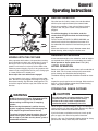
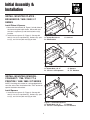
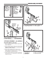
ATTACHMENT
OPERATOR’S
MANUAL
Turbo Clean Sweep
Twin Catcher
Turbo Clean Sweep Twin Catcher
Mfg. No.
1694153
1694693
Description
Turbo Clean Sweep Twin Catcher (Multiple Applications)
Turbo Clean Sweep Twin Catcher (Multiple Applications)
1723846
Revision 06
Rev 4/2005
TP 100-2599-06-AT-UV
Table of Contents
Safety Rules & Information
General Warnings............................................2
Safety Decals ..................................................2
Catcher Assembly - All Models
Assemble Supports & Hitch.............................5
Install Cover & Bags ........................................6
Assemble & Install Tubes ................................6
General Operating Information
Mowing with the Triple Catcher........................3
Recommended Accessories............................3
After Operation ................................................3
Storing the Grass Catcher ...............................3
Normal Removal & Installation
Removal...........................................................7
Installation .......................................................7
Installation with a Tiller
Initial Setup......................................................8
Installation & Removal .....................................8
Initial Assembly & Installation
Install Mounting Plates - Broadmoor / 1600 /
2600 / LT Series
Install Plates & Spacers...................................4
Hardware Identification & Torque Specifications
Chart..............................................................10
Install Mounting Plates - Conquest / 1700 / 2700
/ YT & Prestige / 1800 / 2800 / GT Series
Install Spacers .................................................4
NOTE: In these instructions, “left” and “right” are
referred to as seen from the operating position.
1
Safety Rules
& Information
Read these safety rules and follow them closely. Failure to obey these rules could result in loss of control of
unit, severe personal injury or death to you, or bystanders, or damage to property or equipment. The triangle
in text signifies important cautions or warnings which must be followed.
GENERAL WARNINGS
• Know the unit’s controls and how to stop quickly.
READ THE OPERATOR’S MANUALS.
• Read and obey all safety decals.
• Only allow responsible adults, who are familiar with
the instructions, to operate the unit.
• Disengage the PTO. Shut off the engine and wait for
all moving parts to stop before attaching, adjusting,
or disconnecting any part of the collection system.
• Check the collection system to make sure it is bolted
tightly to the unit.
• DO NOT operate the unit without either the entire
grass catcher or the deflector in place.
• Turn off the PTO to disengage the blades when not
mowing.
• DO NOT mow in reverse. Always look down and
behind before and while travelling in reverse.
• DO NOT turn sharply when travelling alongside a
building or any object. Slow down before turning.
• DO NOT carry passengers.
• When collection system is removed from the mower
deck, the deflector must be properly installed.
• Collector bags are subject to deterioration and wear
during normal use. Inspect the bag periodically for
tears, holes, or weak spots and replace with a new
bag that meets manufacturer’s durability standards.
• If the mower stalls or the collector chute plugs:
1. Disengage the PTO;
2. Stop the engine and remove the key;
3. Set the parking brake, and wait for all moving
parts to stop.
4. Remove the foreign object or clear the chute
with a piece of wood before restarting the engine.
NEVER place hands into COLLECTOR OR
MOWER housing to clear jammed objectS.
Blower OR MOWER may rotate when object is
removed.
• For added stability and to prevent tipping or loss of
control:
a. Use reduced speed on uneven ground and
when turning corners.
b. Reduce loads on hillsides. It is recommended
that the collection system be kept only half full
when negotiating any slopes. Start mowing on
slopes when the collection system is empty.
c. Mow up and down the face of slopes; never
across the face of any slope.
• When operating on slopes, use front counterweights. Never operate on slopes greater than
17.6% (10°).
SAFETY DECALS
These labels are easily applied and will act as a constant
visual reminder to you, and others who may use the
equipment, to follow the safety instructions necessary for
safe, effective operation.
This unit has been designed and manufactured to provide you with the safety and reliability you would expect
from an industry leader in outdoor power equipment
manufacturing.
Although reading this manual and the safety instructions
it contains will provide you with the necessary basic
knowledge to operate this equipment safely and effectively, we have placed several safety labels on the unit to
remind you of this important information while you are
operating your unit.
ATTACHMENT DECALS
WARNING
WARNING
• This shield must be
in place at all times
during operation.
• Do not open cover with engine running.
• Do not operate mower without the
complete catcher in place
• When operating on slopes, refer to
operator's manual for counterweights.
All DANGER, WARNING, CAUTION and instructional
messages on your rider, attachments and mower should
be carefully read and obeyed. Personal bodily injury can
result when these instructions are not followed. The
information is for your safety and it is important! The
safety decals below are on your product.
1704405
Decal - WARNING Do Not
Open Cover
Part Number 1704405
If any decals are lost or damaged, replace them at once.
See your local dealer for replacements.
• Mower deflector
must be in down
position when
blower is removed.
1717291
Decal - WARNING
Part Number
1717291
Read and obey all operation and warning decals.
TP 600-2562-01-AT-SMA
2
General
Operating Instructions
BEFORE OPERATION
Clear the lawn of all sticks, stones, wire and other debris
which may be caught or thrown by the mower blades.
Check grass condition. If wet, wait until later in the day.
If grass is wet, the grass catcher is likely to become
plugged.
For efficient bagging, air circulation under the
mower deck, through the chute and into the bag is
very important.
For this reason, BEFORE YOU BEGIN MOWING you
should make certain the underside of the mower and
the underside of the catcher lid are free from grass and
debris.
Make sure that there is a snug fit between mower deck,
blower housing, tubes, and grass catcher cover.
REQUIRED ACCESSORIES
MOWING WITH THE CATCHER
A front-mounted weight carrier and 66 lbs. worth of weights
are required when using this rear-mounted grass catcher.
Never operate on slopes greater than 17.6% (10°).
Always operate with throttle at full speed when mowing.
Grass should be cut often, and not too short. If grass is
too long or lush it may be necessary to keep ground
speed to a minimum or to cut only half the width of the
mower to prevent clogging. If grass is long, operate with
mower in high cutting position for first pass, cutting again
in a lower position on a second pass.
AFTER OPERATION
Remove any debris from the the screen on the underside of
the lid. Note: The lid screen can be partially removed for
easier cleaning and should be cleaned regularly.
Do not open the cover with mower engaged.
The blower housing and tube should be removed for cleaning.
If a large amount of cut grass is spilling out from under
deck, the tube may be plugged or the bags may be full—
discontinue mowing, stop the rider, disengage the PTO,
shut off the engine and then empty the catcher or clear
the tube.
Inspect the grass bags for wear or damage. Make sure that
there is a snug fit between mower deck, blower housing,
tubes, and grass catcher cover.
STORING THE GRASS CATCHER
CAUTION
WARNING
Do not leave grass in bagger containers. Empty
containers after each use and before storing.
Failure to do so may result in spontaneous
combustion which could develop into a fire.
ALWAYS shut off the tractor. Disengage the PTO,
and allow all moving parts to stop BEFORE
disconnecting or clearing tube, or emptying
catcher.
Before leaving the operator’s position for any
reason, engage the parking brake, disengage the
PTO, stop the engine and remove the key.
Clean the grass catcher thoroughly using a mild detergent
(other products may damage the tube). Remove any debris
from the the screen on the underside of the lid.
To reduce fire hazard, keep the engine, rider and
mower free of grass, leaves and excess grease.
Do not stop or park rider over dry leaves, grass or
combustible materials.
If paint has been scratched on metal parts, touch up with
paint, or apply a thin film of oil to prevent corrosion.
Store in a dry area. Dry thoroughly before storing for a long
period of time. Always store away from moisture.
3
Initial Assembly &
Installation
INSTALL MOUNTING PLATES BROADMOOR / 1600 / 2600 / LT
SERIES
A
B
C
Install Plates & Spacers
1. Mount the side brackets (B, Figure 1) to both sides of
the frame using the holes shown. Secure with one
3/8-16 x 1 capscrew (C) and 3/8-16 nylock nut (A)
per side.
2. Install the rear spacers (C, Figure 2). Secure with
two 1/2-13 x 2-1/2 capscrews (E), washers (D), spacers (C), and 1/2-13 nylock nuts (A) per side.
Figure 1. Install Side Brackets
A. Nylock Nut, 3/8-16
C. 3/8-16 x 1
B. Side Bracket
A
C
D
D
B
Figure 2. Install Rear Spacers
A. Nylock Nuts, 1/2-13
B. 1/2-13 x 2-1/2 Capscrew
INSTALL MOUNTING SPACERS CONQUEST / 1700 / 2700 / YT &
PRESTIGE / 1800 / 2800 / GT SERIES
C. Spacers
D. 1/2” Washers
A
C
NOTE: If installing this catcher on a unit equipped with a
rear tiller, refer to the “Installation with a Tiller” section for
special installation instructions.
D
Install Spacers
1. Install the rear spacers (C, Figure 3). Secure with
two 1/2-13 x 2-1/2 capscrews (E), washers (D), spacers (C), and 1/2-13 nylock nuts (A) per side.
D
Figure 3. Install Rear Spacers
A. Nylock Nuts, 1/2-13
C. Spacers
B. 1/2-13 x 2-1/2 Capscrew D. 1/2” Washers
4
B
Initial Assembly & Installation
Use this
upright with
Broadmoor /
1600 / 2600 /
LT Series
Use this
upright with
Prestige /
1800 / 2800 /
YT &
Conquest /
1700 / 2700 /
GT Series
C
B
Figure 4. Upright Identification
D
A
A
Conquest &
Broadmoor
Mounting
Holes
Figure 6. Assemble Catcher Frame (Prestige Shown)
A. 3/8-16 Nut & Lockwasher C. 3/8-16 x 1 Capscrews
B. Upright Support Assy. D. Lower Support
D
Prestige
Mounting
Holes
B
A
C
Figure 5. Assemble Catcher Frame
A. Upright Support
C. Horizontal Support
B. 3/8-16 x 7/8 Capscrew
D. 3/8-16 Whizlock Nut
CATCHER ASSEMBLY - ALL MODELS
C
Assemble Supports and Hitch
B
D
1. Refer to Figure 4 to select the proper upright support
for your application.
B
2. Bolt the upright support (A, Figure 5) to the horizontal
support (C). Secure with 3/8-16 x 7/8 capscrews (B)
and 3/8-16 whizlock nuts (D).
C
A
3. Bolt the lower support plate (D, Figure 6) to the
upright support (B) using two 3/8-16 x 1 capscrews
(C), lockwashers, and 3/8-16 nuts (A).
A
Figure 7. Assemble Catcher Frame (Prestige Shown)
A. 3/8-16 Nuts &
C. 3/8-16 x 1-1/4 Capscrews
Lockwashers
D. Support Assembly
B. Side Plates
4. Install the hitch side plates (B, Figure 7) and secure
with four 3/8-16 x 1-1/4 capscrews (C), lockwashers,
and 3/8-16 nuts (A).
5
Initial Assembly & Installation
A
B
C
A
B
C
D
Figure 9. Install Cable
A. Cable
B. Support
E
C. Washer
E
G
F
F
D
C
H
I
B
A
Figure 8. Install Catcher (Prestige Shown)
A. #10-32 Nut
F. Bags
B. Handle
G. Hair Pin Clip
C. #10-32 x 1/2 Screw
H. Catcher Hitch
D. Cover
I. Spacers
E. Hinge Pin
Figure 10. Install Tubes
A. Flange Nut
B. Clip
C. #10-32 x 1/2
Screw & Washer
D. Lower Tube
E. #10-32 Nut & Washer
F. Upper Tube
Install Cover and Bags
1. Mount the catcher hitch (H, Figure 8) on the frame
spacers (I).
Assemble & Install Tubes
2. Hang the bags (F) on the horizontal support.
NOTE: Install turbo blower at this time.
3. Install the handle (B) inside the cover. Secure with
two #10-32 x 1/2” screws (C) and #10-32 nuts (A).
1. Locate the lower tube (D, Figure 10) and upper tube
(F).
4. Rest the cover assembly (D) on the bags (F).
2. Assemble the upper and lower tubes using two #1032 x 1/2 screws (C), washers, and #10-32 nuts (E).
5. Install the two hinge pins (E) and secure with hair pin
clips (G).
3. Insert the tube assembly into the catcher.
6. Open the cover and fasten cable (A, Figure 9) to support (B). The looped cable end fits over washer (C).
4. Connect the lower tube (D) to the turbo. Lock the clip
(B) on the flange nut (A).
6
Normal Removal &
Installation
A.
B.
C.
D.
E.
F.
G.
Tubes
Hair Pin Clip
Frame Spacers
Bags
Clevis Pin
Cover
Clip
F
A
E
G
D
B
C
Figure 11. Normal Removal & Installation (Prestige Shown)
WARNING
Installation
1. Mount the catcher frame on the frame spacers (C,
Figure 11).
OPERATION WITHOUT TURBO & CATCHER
For operation without turbo, the mower deflector
MUST be properly installed in the down position and
retained by the spring latch (see turbo operator’s
manual).
2. Install the bags (D).
3. Install the cover (F). Secure with the clevis pins (E)
and hair pin clips (B).
4. Connect the cover cable (Figure 9).
NORMAL REMOVAL & INSTALLATION
5. Insert the tubes (A, Figure 11) into the catcher and
connect to the turbo. Be sure the clip (G) is secured
over the top of the turbo flange nut.
Removal
1. Disconnect the tubes (A, Figure 11) from the turbo
and remove them from the catcher.
2. Remove the hair pin clip (B) and clevis pin (E) securing the cover (F). Disconnect the cable (see Figure
8). Remove the cover (F).
3. Remove and empty the bags (D).
4. Remove the catcher frame from the frame spacers
(C).
7
Installation with a Tiller
C
B
I
H
A
D
G
F
A
B
C
D
E
Figure 13. Installation (Prestige Shown)
A. Tiller Hitch
C. Hair Pin Clip
B. Clevis Pin
D. Support Assembly
Figure 12. Initial Setup (Prestige Shown)
A. Nuts, 5/16-18
G. Carriage Bolts,
B. Lockwashers, 5/16
3/8-16 x 3/4
C. Plate
H. Nuts & Lockwashers,
D. Spacers
3/8
E. Lower Support
I. Upright Support
F. Carriage Bolts,
5/16-18 x 1-1/4
INSTALLATION WITH A TILLER
Initial Setup
Installation & Removal
Note: Use the short upright bracket (refer to Figure 4).
1. Rest the support assembly (D, Figure 13) on the tiller
hitch (A) cross-bar.
1. Assemble the lower support (E, Figure 12), spacers
(D), and plate (C) as shown).
2. Secure the catcher to the tiller hitch using two clevis
pins (B) and hair pin clips (C).
2. Bolt the lower plate assembly (E) to the upright support (I) using four 3/8-16 x 3/4 carriage bolts (G),
lockwashers, and 3/8-16 nuts (H).
3. See “Normal Removal & Installation” for remaining
procedures.
8
Notes
9
Hardware Identification & Torque Specifications
Common Hardware Types
Torque Specification Chart
Hex Head Capscrew
FOR STANDARD MACHINE HARDWARE (Tolerance ± 20%)
Washer
Hardware
Grade
Lockwasher
Carriage Bolt
No
Marks
SAE Grade 2
Hex Nut
Size Of
Hardware
Standard Hardware Sizing
8-32
8-36
10-24
10-32
1/4-20
1/4-28
5/16-18
5/16-24
3/8-16
3/8-24
7/16-14
7/16-20
1/2-13
1/2-20
9/16-12
9/16-18
5/8-11
5/8-18
3/4-10
3/4-16
7/8-9
7/8-14
1-8
1-12
When a washer or nut is identified as 1/2”, this is the
Nominal size, meaning the inside diameter is 1/2 inch; if a
second number is present it represent the threads per inch
When bolt or capscrew is identified as 1/2 - 16 x 2”, this
means the Nominal size, or body diameter is 1/2 inch; the
second number represents the threads per inch (16 in this
example, and the final number is the body length of the
bolt or screw (in this example 2 inches long).
The guides and ruler furnished below are designed to
help you select the appropriate hardware and tools.
0
1/4
Nut, 1/2”
1/2
Inside
Diameter
3/4
1
1/4
1/2
3/4
Screw, 1/2 x 2
2
1/4
Body
Diameter
in/lbs
ft/lbs
19
20
27
31
66
76
11
12
20
23
30
35
50
55
65
75
90
100
160
180
140
155
220
240
Nm.
2.1
2.3
3.1
3.5
7.6
8.6
15.0
16.3
27.2
31.3
40.8
47.6
68.0
74.8
88.4
102.0
122.4
136
217.6
244.8
190.4
210.8
299.2
326.4
SAE Grade 5
in/lbs
ft/lbs
30
31
43
49
8
10
17
19
30
35
50
55
75
90
110
120
150
180
260
300
400
440
580
640
SAE Grade 8
Nm.
in/lbs
ft/lbs
Nm.
3.4
3.5
4.9
5.5
10.9
13.6
23.1
25.8
40.8
47.6
68.0
74.8
102.0
122.4
149.6
163.2
204.0
244.8
353.6
408.0
544.0
598.4
788.8
870.4
41
43
60
68
12
14
25
27
45
50
70
80
110
120
150
170
220
240
386
420
600
660
900
1,000
4.6
4.9
6.8
7.7
16.3
19.0
34.0
34.0
61.2
68.0
95.2
108.8
149.6
163.2
204.0
231.2
299.2
326.4
525.0
571.2
816.0
897.6
1,244.0
1,360.0
NOTES
1. These torque values are to be used for all hardware
excluding: locknuts, self-tapping screws, thread forming
screws, sheet metal screws and socket head setscrews.
2. Recommended seating torque values for locknuts:
a. for prevailing torque locknuts - use 65% of grade 5
torques.
b. for flange whizlock nuts and screws - use 135% of
grade 5 torques.
3. Unless otherwise noted on assembly drawings, all torque
values must meet this specification.
1/2
Body
Length
3/4
3
1/4
1/2
3/4
4
Wrench & Fastener Size Guide
1/4
5/16
3/8
1/4” Bolt or Nut
Wrench—7/16”
5/16” Bolt or Nut
Wrench—1/2”
3/8” Bolt or Nut
Wrench—9/16”
7/16
DIA.
7/16” Bolt or Nut
Wrench (Bolt)—5/8”
Wrench (Nut)—11/16”
1/2
DIA.
1/2” Bolt or Nut
Wrench—3/4”
MANUFACTURING, INC.
500 N Spring Street / PO Box 997
Port Washington, WI 53074-0997
www.simplicitymfg.com
© Copyright 2005 Simplicity Manufacturing, Inc.
All Rights Reserved. Printed in USA.