1
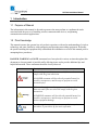
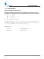
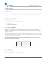
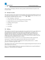
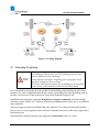
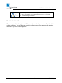
Making connections in a high-speed world
SLE100 Fast Ethernet Links
Installation Manual
P/N 590-00532
Revision A
June 2008
TM
SLE100 Installation Manual
Copyright Notice & Disclaimer
Copyright © 2004 – 2008 BridgeWave Communications. All rights reserved.
Printed in the USA
No portion of this publication may be reproduced, copied, or distributed without the written
consent of BridgeWave Communications. BridgeWave reserves the right to update or change the
material in this publication at any time without notice. BridgeWave has made every effort to
ensure that the information and the instructions contained in the publication are adequate and is
not responsible for any errors or omissions due to typing, printing, or editing of this document.
Purchasers of BridgeWave products should make their own evaluation to determine the
suitability of each such product for their specific application. BridgeWave’s obligations
regarding the use or application of its products shall be limited to those commitments to the
purchaser set forth in its Standard Terms and Conditions of Sale for a delivered product.
This publication has been prepared for professional and properly trained personnel, and the
customer assumes full responsibility when using the information herein.
Export Control
All BridgeWave radio products are restricted commodities that fall under ECCN 5A002 of the
Department of Commerce. These products are "ENC restricted" under section 740.17(b)(2) of
the Export Administration Regulations (EAR). BridgeWave products may only be exported, reexported, transferred, or retransferred in accordance with Export Administration Regulations.
Diversion contrary to U.S. law is expressly prohibited.
Product Compatibility
While every effort has been made to verify operation of this product with many different
communications products and networks, BridgeWave makes no claim of compatibility between
its products and other vendors’ equipment. It is assumed that users have thoroughly evaluated
this product’s performance in the communications environment in which it will be used.
ii
590-00532, rev A
TM
SLE100 Installation Manual
Safety
CAUTION, WARNING, and DANGER statements have been strategically placed in the text to
alert personnel of possible hazards. These statements must be closely observed.
The following general safety precautions must be observed during all phases of operation and
service of the products covered in this manual. Failure to comply with these precautions or with
specific warnings elsewhere in this manual willfully violates standards of design, manufacture,
and intended use of the product. BridgeWave assumes no liability for the customer’s failure to
comply with these requirements.
•
These BridgeWave radios meet all applicable FCC safety requirements for general
population exposure to radio frequency emissions; however, it is best to avoid prolonged,
unnecessary exposure to the front of the radio while it is operating.
•
The outdoor equipment must be properly grounded to provide some protection against
voltage surges and built-up static charges. In the event of a short circuit, grounding
reduces the risk of electrical shock.
For installations in the U.S.A., refer to Articles 810830 of the National Electrical Code,
ANSI/NFPA No. 70, for information with respect to proper grounding and applicable
lightning protection for DC cables. The installer must also follow any additional local
building and electrical code regulations.
For installations in all other countries, implement protection in accordance with the
safety standards and regulatory requirements of the country where the equipment is to be
installed.
•
Do not install or operate this equipment in the presence of flammable gases or fumes.
Operation of any electrical instrument in such an environment constitutes a definite
safety hazard.
•
Do not install substitute parts or perform any unauthorized modification to the
equipment. Changes or modifications not expressly approved by BridgeWave can void
the user’s authority to operate the equipment.
iii
590-00532, rev A
TM
SLE100 Installation Manual
Regulatory Information
This device complies with FCC Part 15.255 and Industry Canada RSS-210.
Operation is subject to the following two conditions:
(1)
This device may not cause harmful interference, and,
(2)
This device must accept any interference that may cause undesired operation.
Equipment Precautions
Water and Moisture - These BridgeWave radios are designed to withstand weather conditions
typically encountered when installed outdoors.
Power Sources - This product should only be operated with the type of power source provided by
BridgeWave Communications Inc.
Avoid applying force to the antenna radome, since this may damage the internal feed horn.
Never rest the unit on a surface with the radome facing down.
iv
590-00532, rev A
TM
SLE100 Installation Manual
Table of Contents
Copyright Notice & Disclaimer ................... ii
3.8
Antenna Alignment ......................... 24
Export Control ............................................. ii
3.9
QUAL & RSL Test Cable ............... 27
Product Compatibility.................................. ii
4
Safety ........................................................... iii
Configuring Network Equipment ....... 30
4.1
Network Port Statistics................... 30
Regulatory Information............................... iv
Equipment Precautions ............................... iv
1
2
3
Introduction ............................................ 1
1.1
Purpose of Manual........................... 1
1.2
Prior Knowledge .............................. 1
1.3
Contact Information ......................... 2
Appendix A: Troubleshooting..................... 31
Appendix B: RSL Voltage vs. Distance ...... 33
Std. Limited Warranty & SW License ....... 34
Site Planning ........................................... 3
2.1
General ............................................ 3
2.2
Equipment Checklist ........................ 3
2.3
Line of Sight (LOS) .......................... 3
2.4
Link Distance ................................... 3
2.5
Antenna Location ............................. 4
2.6
Cabling............................................. 4
2.7
Grounding & Lightning ................... 5
2.8
Environmental .................................. 6
Installation .............................................. 7
3.1
Equipment Unpacking ...................... 7
3.2
Equipment Inventory ........................ 7
3.3
Installation Tools ............................. 9
3.4
Radio Mount Installation ............... 10
3.5
Radio Installation........................... 16
3.6
Cable Installation........................... 19
3.7
Optional Ice Shield Canopy
Installation ................................................. 21
v
590-00532, rev A
TM
SLE100 Installation Manual
1 Introduction
1.1 Purpose of Manual
The information in this manual is directed to persons who must perform or coordinate the tasks
associated with the process of installing wireless communication devices, and planning
communication network applications.
1.2 Prior Knowledge
This manual assumes the operator has at least basic experience with and an understanding of wireless
technology and some familiarity with configuring and operating networking equipment. Preferably,
the person installing this equipment fully understands the information covered in this manual prior to
attempting these procedures.
DANGER, WARNING and NOTE statements have been placed in various sections throughout this
document to alert personnel of possible traffic affecting issues and to provide additional tips and
helpful information. These statements should be closely observed.
Symbol
Description
Indicates that personal injury can result if the user does not
comply with the given instruction.
A DANGER statement will describe the potential hazard, its
possible consequences, and the steps to perform to avoid
personal injury.
Indicates that equipment damage, process failure and/or loss of
data can result if the user does not comply with the given
instructions.
A WARNING statement will describe the potential hazard, its
possible consequences, and the steps to perform to avoid
serious equipment damage.
Provides supplementary information to emphasize a point or
procedure, or provides a tip for easier operation.
1
590-00532, rev A
TM
SLE100 Installation Manual
1.3 Contact Information
Technical Assistance and Customer Service
BridgeWave distributors are authorized local service providers and are responsible for immediate
customer support. If problems are not resolved, contact BridgeWave Customer Service for assistance:
Santa Clara, CA USA
Tel:
408.567.6906
Fax:
408.567.0775
Email: [email protected]
Return Material Authorization (RMA)
Should BridgeWave equipment have to be returned for repair or replacement, an RMA number must
be obtained from BridgeWave or the local BridgeWave distributor. When returning equipment, be
sure to write the RMA number on the outside of the shipping carton.
BridgeWave Sales
E-mail:
[email protected]
Inside Sales:
+1.866.577.6908
2
590-00532, rev A
TM
SLE100 Installation Manual
2 Site Planning
2.1 General
Before the start of an installation a survey should be conducted of the proposed area of the site(s). The
survey personnel should be fully familiar with the details required to install the BridgeWave radio
system.
2.2 Equipment Checklist
The survey team will need the following equipment:
•
Tape Measure
•
Site Survey Report Form
2.3 Line of Sight (LOS)
BridgeWave Wireless links require line-of-sight for proper operation. Fortunately, the links are
relatively short and obstructions in the path can easily be identified. Binoculars can ease viewing in
poor light conditions.
The planning should include an investigation into future building plans that could block the LOS path,
and other long-term incremental obstructions such as trees. Intermittent obstructions such as aircraft at
a nearby airport should also be considered.
The following table details the minimum clearance needed from obstacles near the path in order to
ensure the radios will operate properly.
Path Length
(meters)
250
500
Minimum Clearance
(meters)
0.56
0.79
Table 2-1: Minimum Mid Path Clearance Requirements
2.4 Link Distance
The Minimum Link Distance is 65 feet (20 meters)
3
590-00532, rev A
TM
SLE100 Installation Manual
The SLE100 provides highly reliable all-weather operation at half-mile distances anywhere in the
USA and Canada.
2.5 Antenna Location
The optimum location for the antennas must be determined. The ideal location should provide for ease
of erecting and mounting the antenna, as well as unimpeded Line-Of-Site (LOS) to the other site. The
following factors should be taken into account:
•
Type of mounting—wall or pole
•
Location where the CAT5 cable wiring will enter/exit the building
•
Length of cable runs (not to exceed 100 meters, 328 feet)
•
Grounding connection points
•
Obstructions
•
Accessibility
2.6 Cabling
The installation site should be inspected to determine the run paths for the Cat5 copper cable from the
radio equipment to the surge arrestor and PoE Injector termination points. Locations for roof
penetration should be identified. The routing and securing of all cables should conform to all
applicable codes and requirements. Depending on the likelihood of damage due to foot traffic or
equipment movement, cabling conduit may be required. The maximum cable run length as specified
for the equipment being installed must not be exceeded.
Each SLE100 radio includes a 100-240 VAC power adaptor suitable for indoor operation that
converts the AC voltage from the standard electrical outlet in the wall to 48 volts DC.
The Cat5 cable that is used outside the building must be outdoor (plenum) rated (i.e., weatherprotected) or installed in applicable conduit.
The maximum end-to-end Cat5 cable run from network equipment through the PoE Injector and to the
SLE100 radio unit is 100 meters.
Figure 2-1 provides a diagram detailing the equipment and cabling found on a typical installation of
BridgeWave’s SLE100 60GHz radio equipment:
4
590-00532, rev A
TM
SLE100 Installation Manual
Figure 2-1 Cabling Diagram
2.7 Grounding & Lightning
Proper grounding of the outdoor equipment reduces
electromagnetic interference, provides lightning protection, and
protects against electrical discharge.
Using improper techniques in lightning prone geographic areas
may pose a danger to local personnel.
The source and connection points for the building-to-earth ground
in the vicinity of the antenna location should be determined.
It is recommended to integrate the radio ground into the building ground utilizing the pole mount
hardware. For wall or ungrounded pole mounts connect a grounding wire to the grounding point on
the radio. Select the size of the ground wire based on the National Electrical Code.
In addition to grounding the equipment, BridgeWave strongly recommends, and local building
codes may require, that the Cat 5 cable be protected from lightning strikes by the use of an additional
surge suppressor.
The surge suppressor must be installed at the point where the Cat 5 cable exits/enters the building,
however use of a surge suppressor at the radio unit is optional since power cable surge suppression is
built into the unit.
The BridgeWave SLE100 includes surge suppressors at both ends of the Cat 5 cable.
5
590-00532, rev A
TM
SLE100 Installation Manual
For more information on recommended accessory devices and
kits, contact BridgeWave Sales
2.8 Environmental
The structure to which the equipment will be mounted must be adequate to bear all wind and other
weather conditions. The environmental conditions at the location must conform to the operating
environment specified for the equipment.
6
590-00532, rev A
TM
SLE100 Installation Manual
3 Installation
3.1 Equipment Unpacking
The radio system equipment will arrive in two boxes: one box for the low-band radio and one box for
the high-band radio. Locate the desired box (low-band or high-band) before beginning installation by
checking the label on the outside of the box or on the radio itself. It is recommended that the shipping
cartons and packing materials be retained in the event that it is necessary to return any equipment.
Unpacked radios can be identified by the color of their labels
found on their front faces or inside the unit after removing the
plastic back weather cover. The blue color label indicates a high
band radio and the red color label indicates a low band radio. See
Figure 3-8 for further details.
Avoid applying force to the antenna radome, since this may
damage the internal feed horn. Never rest the unit on a surface
with the radome facing down.
Radome
3.2 Equipment Inventory
Each carton is accompanied by a packing list. Verify the contents of the carton against the packing
list. The following are inventory lists for a typical system.
Qty
Description
2 ea.
SLE100 radios (1 low-band & 1 high-band)
2 ea.
Wall Mount Kits
2 ea.
Pole Mount Kits (required only when mounting the radio onto a pole)
2 ea.
Visual Alignment Tool (VAT)
2 ea.
Standard Power Supply (Indoor rated, 100-240VAC input to 48VDC output)
7
590-00532, rev A
TM
SLE100 Installation Manual
1 ea.
CD-ROM containing Installation Manual (1 provided per pair of radios)
1 ea.
Hard reset box
1 ea.
9/16-inch wrench
BridgeWave10-inch Antenna Wall Mount Kit Parts List
Item
1
2
3
4
5
6
Description
Mount Bracket
Radio Yoke
Teflon Shim
⅜ Split Lock Washer
⅜ Flat Washer
⅜-16 x ¾ bolts
Qty.
1
1
1
4
4
4
BridgeWave Pole Mount Kit Parts List
Item
1
2
3
4
5
6
Description
Pole Clamp
⅜-16x9in Threaded Rod
⅜ Split Lock Washer
⅜ Flat Washer
⅜-16 Hex Nut
⅜-16 x ¾ bolts
Qty.
4
4
14 (2 spare)
14 (2 spare)
13 (1 spare)
6 (2 spare)
The radio is sealed at the factory with warranty stickers on the
inner (metal) cover of the radio. There is no need to open this
cover in the field. Tampering with these seals will void the
warranty.
8
590-00532, rev A
TM
SLE100 Installation Manual
3.3 Installation Tools
The following tools, should be used for installing the radio:
•
Screwdriver, slotted 0.1 inch (2.5mm) wide
•
Open-end wrench 11/32 (9mm)
•
Open-end wrench 9/16 (14mm), 2 ea. (Supplied by BridgeWave)
•
Ratchet with 6 inch (15cm) extension and 9/16 inch (14mm) deep socket
•
Electrical tape
•
Fish tape for pulling cable
•
Cable tie wraps
•
Hand-held DVM (digital voltmeter) with standard banana plug receptacles
•
RJ45 connectors
•
RJ45 crimp tool
9
590-00532, rev A
TM
SLE100 Installation Manual
3.4 Radio Mount Installation
The SLE100 radio unit can be mounted to a wall or attached to a pole. Instructions for assembling the
mounting brackets for wall and pole mount applications are described in the sections below.
Wall Mounting Instructions
The diagram in Figure 3-1 shows the required parts and assembly for mounting the bracket to a wall
followed by detail instructions.
Figure 3-1 Wall Mount Assembly Diagram
10
590-00532, rev A
TM
SLE100 Installation Manual
1.
Install 4 mounting bolts in the wall at the desired location. The template provided in Figure 3-3
can be used to establish the hole pattern on the wall. The bolts (normally ⅜-16) should extend
0.8 to 3.0 inches (2cm to 7.5cm) from the wall and be strong enough to secure the radio to the
wall under foreseeable environmental conditions. The environmental conditions may include,
but not limited to, wind, rain, ice, etc. Depending on the wall material the mount is being
attached to, a different size bolt may be appropriate. In this case, bolts up to ¾ inch in diameter
may be used.
1. Secure the ‘Wall-Mounting Bracket’ to the wall using the appropriate sized nuts, lock washers,
and flat washers for the bolts used.
2. Attach the Yoke Mounting Bracket to the mount, with Teflon shim in-between, using 2 each of
the supplied ⅜-16 x ¾ bolts, ⅜ lock washers, and ⅜ flat washers. Tighten the bolts just enough
to allow the yoke to move back and forth without binding.
3/8 Lock Washer
3/8-16x3/4 Bolts
3/8 Flat Washer
Mounting Bracket
Teflon Shim
Radio Yoke
Figure 3-2 Attaching the Yoke to the Mounting Bracket
11
590-00532, rev A
TM
SLE100 Installation Manual
6.25 inches
(15.9 cm)
3.13 inches
(8.0 cm)
Figure 3-3: Wall Mount Hole Drilling Template
12
590-00532, rev A
TM
SLE100 Installation Manual
Pole Mounting Instructions
The pole mount kit can be used to secure the mount to a pole with diameter from 2.0 to 4.5 inches (50
to 115 mm). Listed below are the steps required to assemble the bracket for a pole mount application:
1. Pre-assemble the pole mount brackets by attaching the 4 All-Thread rods to two of the pole
mount brackets using eight ⅜-16 x ¾ hex nuts and four each ⅜ split lock washers, and ⅜ # 8
flat washers, as shown in Figure 3-4. This creates a U-Bolt type arrangement.
Figure 3-4 Pole-Mount Bracket Assembly
The ⅜-16 x ¾ hex nuts on the inside of the pole clamps do not
require any washers since they are only holding the threaded rods
in place and do not bear any load. These hex nuts secure the All
Thread rods to the pole clamps making it easier to align the
clamps on each side of the pole.
2. Attach two pole mount brackets to the wall-mounting bracket using 4 each ⅜-16 x ¾ bolts, ⅜
Split lock washers, and ⅜ # 8 flat washers.
13
590-00532, rev A
TM
SLE100 Installation Manual
Figure 3-5 Attaching Pole Mount Brackets to Wall Mount Bracket
3. Attach the Yoke Mounting Bracket to the mount, with Teflon shim in-between, using 2 each of
the supplied ⅜-16 x ¾ bolts, ⅜ lock washers, and ⅜ flat washers. Tighten the bolts just enough
to allow the yoke to move back and forth without binding.
Figure 3-6 Attaching the Yoke to the Mounting Bracket
14
590-00532, rev A
TM
SLE100 Installation Manual
4. Secure the assembled Yoke Mount to the pole using the preassembled pole mount brackets
from Step 13, and 4 each ⅜-16 nuts, ⅜ lock washers, and ⅜ flat washers.
Figure 3-7 Attaching Pole Mount Brackets and Yoke to Pole
15
590-00532, rev A
TM
SLE100 Installation Manual
3.5 Radio Installation
Perform the following steps to attach the radio to the Yoke Mounting Bracket:
1.
Determine desired polarization of the link, vertical or horizontal, and orient the radio
accordingly using the diamond shaped polarity indication stickers shown in Figure 3-8.
When the radio comes from the factory, the mounting plates are in
the vertical polarization position, that is, the diamond marking on
the front of the radio housing is to the right when viewed from the
front. For horizontal polarization, the mounting plates should be
moved so that the diamond is at the top when viewed from the
front. Verify that the flexible conduit entrance is on one of the
lower sides of the radio.
Figure 3-8: Polarization Diamond Orientations
The blue color label indicates a high band radio and the red color
label indicates a low band radio
16
590-00532, rev A
TM
SLE100 Installation Manual
It is critically important during installation to ensure the
radios on each side of the link are in the same polarization
(horizontal-horizontal or vertical-vertical). A link that has a
radio on one side of the link set in the horizontal polarization
and the other side of the link set in the vertical polarization
will not operate properly.
It is also critically important that a high-band radio is paired with
a low-band radio to ensure the system will operate properly. Prior
to installation check each radio to verify one is a high-band and
the other is a low-band version. The label on the radio will
indicate the band (blue for high or red for low).
2.
Place the radio in the yoke; the two up/down pivot bolts should rest in the U’s cut in the
yoke as shown in Figure 3-9. The drain hole and conduit fitting should be pointed down.
Figure 3-9 Attaching the Radio to the Yoke
3.
Once the radio has been placed in the yoke mount, insert the bolt in the lower portion of the
yoke to secure the radio. Tighten both the upper and lower elevation lock bolts enough such
that the radio is secured in the mount but is still able to be easily tilted up and down.
17
590-00532, rev A
TM
SLE100 Installation Manual
Figure 3-10: Attaching Radio to Yoke Mount Bracket
4.
Perform steps 1 –3 on both ends of the link.
18
590-00532, rev A
TM
SLE100 Installation Manual
3.6 Cable Installation
1. Install grounding for the radio unit. The preferred method for grounding the radio unit is to
ground the mast (or wall-mount bracket) to a ground source, since this provides the largest
grounding surface contact possible. If this is not possible, then use the following procedure:
A.
Attach the lug of a 10 AWG ground cable to the radio at one of the two #8 holes at the
bottom of the enclosure using a #8-32 bolt, #8 lock washer and #8 flat washers (not
provided).
B.
Connect other end of the ground cable to a nearby building exterior ground location.
2. Run a Cat 5 cable from the SLE100 radio unit to the indoor location where the PoE Injector
will be installed.
3. Connect the Cat 5 cable to the interface labeled “PoE” on the radio unit.
4. Install the PoE Injector in the desired indoor location and connect the Cat 5 cable coming from
the radio unit to the interface labeled “Data & PWR”.
19
590-00532, rev A
TM
SLE100 Installation Manual
5. Next, connect the interface labeled “Data” on the PoE Injector to the network device that will
interface with the SLE100.
6. Connect the site ground to the terminal labeled “GND” on the PoE Injector.
7. Connect the DC plug end of the Power Supply to the receptacle labeled “PWR” on PoE
Injector.
20
590-00532, rev A
TM
SLE100 Installation Manual
8. Plug the AC cord into the power supply and connect to the local AC power. The radio will turn
on.
9. Check the radio ‘Power’ LED status for a green indication. If green the radio is powered on
and is ready for alignment.
3.7 Optional Ice Shield Canopy Installation
The Ice Shield assembly is an optional item and can be ordered in
kit form through a BridgeWave distributor.
3.7.1
Introduction
In northern climates, the buildup of ice or snow on antennas can be a problem for millimeter wave
radio installations. These problems are twofold: the electrical effect of snow and ice built up on the
antenna’s radome; and the mechanical impact of the additional weight of the snow or ice on the
antenna and supporting structure.
The formation of ice or snow on the antennas radome can cause attenuation of the signal to the point
where the link may become severely degraded or unusable. Uneven ice buildup can cause scattering of
the signal, which in turn results in standing waves.
Ice layers are not likely to exist for extended periods, as ice tends to melt. In cold climates when the
radome is below freezing temperature, ice does not stick to it, thus there is no issue. However in
mixed rain-snow-ice storms, ice can stick to the radome, causing the link to operate at less than its
optimal design.
Once the ice has hardened and freezes, the added weight of the ice on the antenna increases the wind
load on the tower or mast, which may cause premature failure of the mounting structure. As ice breaks
apart due to melting, or via its own weight, these large and heavy sheets falling down a tower or mast
can cause damage to antennas or other objects mounted below.
BridgeWave provides an ice shield kit, designed to combat the buildup of ice on BridgeWave’s
wireless bridges. These inexpensive ice shields are easily fitted on the radios during the installation
process.
21
590-00532, rev A
TM
SLE100 Installation Manual
Figure 3.7.1-1: 60 Ice Shield
3.7.2
Optional Kit
The part number for this kit is 515-00913
Refer to the table below for the kit required for your particular application. Each kit contains the
necessary materials for the installation of the ice shield on one radio. Two kits are required per link.
Qty: Description:
1 ea. Ice Shield Canopy
2 ea. 8-32 x 1/2” Screw
3.7.3
Installation Instructions
1. Remove the protective liner from the canopy (if desired)
2. Remove the “O” bolt if equipped
3. Use the supplied screws to attach the Ice Shield to the radio
22
590-00532, rev A
TM
SLE100 Installation Manual
Figure 2: Attaching the Ice Shield
4. Re-install the “O” bolt.
Remove canopy when its not snowing to reduce antenna wind
loading
23
590-00532, rev A
TM
SLE100 Installation Manual
3.8 Antenna Alignment
1. Tighten the mounting bracket azimuth and elevation lock bolts just enough to allow the radio to
pivot up/down and right/left with minimal effort. Tilt the radio so that it roughly points towards
the other end of the link.
2. Thread the Visual Alignment Tool (VAT) into one of the four holes in the front (antenna) face of
the radio so that the o-ring just touches the radio face. The VAT is used to roughly orient
(align) the radio in the correct direction. Select the hole that allows the most convenient viewing
of the other end of the link. The best viewing is achieved with your eye about 13 inches (33cm)
from the VAT mirror. Move the radio such that it is aimed at the point tangent to the top of the red
indicator when all three indicators (green/red/green) are in a line with equal gaps between the
indicators.
24
590-00532, rev A
TM
SLE100 Installation Manual
Mirror
R a d io a t fa r e n d o f lin k
T h e a lig n m e n t a id s n e e d to b e in a s tra ig h t lin e .
T a rg e t, o th e r ra d io , is p la c e d a t to p o f m id d le a id .
R ig h t
25
590-00532, rev A
TM
SLE100 Installation Manual
Radio at far end of link
Aiming Too low
Wrong
6. Verify Link Up LED’s are lit solid on both radios.
7. Slightly rotate each radio up/down and left/right to find the maximum RSL voltage reading. [Note
that the width of the center beam is only 1.4 degrees and the first side-lobe beam is only 2.5
degrees off from center.] Set the radio in the position that results in the highest RSL voltage
reading. See Section 3.9 to determine the proper use of the supplied test cable in order to read
the RSL voltage.
Verify that the RSL voltage falls within the expected range based
on the graph in Appendix B.
8. Begin to tighten the mounting bolts. It is important to tighten the bolts in the following order.
First start with the bolts that control the left/right movement of the radio. These are the bolts on
the yoke portion of the mount behind the radio. Start by tightening the bolt closest to the pole or
wall. Once this is tightened, move to the bolt directly in front of the bolt you just tightened and
slowly tighten this bolt. While tightening the bolts be careful that the radio does not move during
the process. As these bolts are tightened up/down movement of the radio may occur due to the
seating of the mounting bracket and radio yoke. Check the RSL voltage reading to ensure it is still
at its maximum level, and adjust vertical tilt if required. Next, tighten the bolts that allow the
up/down movement of the radio. First tighten the lower bolts on both sides of the yoke bracket.
Once the lower bolts are tightened on both sides of the radio, tighten the upper bolts.
9. Repeat steps 1 to 8 for the peer radio.
10. Connect to the web management interface of each unit and perform an Auto-Calibration from the
‘Maintenance’ page on one end of the link at a time.
11. After both ends of the link are calibrated check the quality voltage using the test cable and a
voltmeter and confirm it indicates 3.3V on each end of the link (i.e., error free).
12. Remove the VAT from the radio, replace the back plastic cover and hand tighten the back cover
nut to the point where the back cover stops (i.e., when it hits the metal ring on the back metal
plate). The installation is now complete.
26
590-00532, rev A
TM
SLE100 Installation Manual
These instructions can also be found on the radio’s back cover.
3.9 QUAL & RSL Test Cable
The alignment procedure is optimized through the use of the provided test cable. The test cable is
designed for use with a digital voltmeter (not provided) to read the Link Quality and Receive Signal
Level (RSL) voltage generated by the radio’s receiver.
The Test Cable contains three banana plugs on one end that provides one common lead, one RSL, and
one Qual lead. This is depicted in Figure 3-11.
Figure 3-11 RSL & Qual Test Leads
A single plug is provided on the other end of the test cable. The single plug connects to the port
labeled ‘Test’ on the radio unit. This test point is shown in Figure 3-12.
27
590-00532, rev A
TM
SLE100 Installation Manual
Figure 3-12: RSL and Quality Test Cable Connection Point
The voltmeter should be set to DC voltage and the x 20 setting. The expected RSL level is dependent
on the distance between the two radio terminals. A chart is provided in Appendix B.
The quality voltage provides an indication of how well the link is performing and is described in the
graph and detailed description below.
3.3
Correctable Errors Detected
3.0
QUAL Voltage (VDC)
NO
ERRORS
2.0
Uncorrectable Errors Detected
1.7
CORRECTED
ERRORS
UNCORRECTED
ERRORS
0.3
Deframer Unlocked (Link Down)
0.0
0
0
Errors
Figure 3-13 Quality Voltage Graph
•
•
Quality Voltages between 3.0V and 3.3V indicate an error-free wireless link.
Quality Voltages between 1.5V and 3.0V indicate a low rate of errors that the forward error
correction will correct. The lower the voltage, the more errors are being corrected.
28
590-00532, rev A
TM
SLE100 Installation Manual
•
Quality Voltages between 0.5V and 1.0V indicate excessive errors in the wireless link that can
not be corrected by the FEC. To indicate this change in error performance, the quality voltage
will drop from 1.5V to 1.0V in a single step.
•
Quality Voltages below 0.5V indicate an unlocked deframer condition. This will be recognized
as a link-down condition.
The following procedure can be used to check the RSL and quality voltages:
1.
To read the RSL value (between 0 and 3.3V), insert GND (ground) and RSL banana plugs into
the voltmeter. Note the RSL voltage. The voltage may be fluctuating; in this case, note the
maximum value seen.
2.
To read the Link Quality value of the radio, insert GND (ground) and QUAL banana plugs
into the voltmeter. Note the Link Quality voltage. After an Auto-Calibration has been performed from
the ‘Maintenance’ page of the web interface the quality voltage should read 3.3V if the link is aligned
on the main antenna beam and there are no obstructions (i.e., trees, buildings, etc…) in the path, the
link distance is within the operating parameters of the radio, and it is not raining heavily.
The SLE100 has been designed to require only minimal user configuration. To perform the
configuration of the Network Management System follow the instructions in the Network
Management manual.
During normal operation, the following conditions should exist at the radio:
•
•
•
•
The power LED should be lit—solid green;
The Link Up LED should be lit—solid green;
The Link Quality BER voltage should be 3.3v, although dips in voltage are acceptable
during periods of significant rain.
Observe the 10/100Base-T LEDs on the interface labeled PoE at each side next to socket
opening. The left one should be green if connected (link up) and the right will be flashing
yellow when there is data traffic. [The picture does not show the 10/100Base-T connector
or LEDs]
Figure 3-14: Radio Link Up and Power LED’s
29
590-00532, rev A
TM
SLE100 Installation Manual
4 Configuring Network Equipment
The networking equipment that is connected to the SLE100 should first be checked to ensure it
operates properly over a wired connection.
We recommend the network equipment on both sides of the link be configured as follows:
•
Port auto-negotiation turned on
•
Port configured to not enter error-disable state due to multiple link up/down
transitions (since these may occur during periods of heavy rainfall)
The radio’s 10/100Base-T port is permanently set to autonegotiate.
4.1 Network Port Statistics
Verify, if possible, the following on the user’s network equipment (connected to the radios), in
addition to verifying these values using the radio’s Network Management System:
•
Link integrity
•
There are no receive errors on the link
•
Network traffic is flowing in both directions.
The radios support all standard Ethernet frame sizes, up to 1632
bytes for un-tagged or 802.1q VLAN-tagged frames.
30
590-00532, rev A
TM
SLE100 Installation Manual
Appendix A: Troubleshooting
The following table provides a summary of possible problems you might encounter while installing a
BridgeWave SLE100 link, along with possible causes and their solutions.
Extensive troubleshooting support and knowledgebase articles are
available at the BridgeWave eSupport knowledgebase online at:
http://bridgewave.com/support/kbrma.htm
Contact BridgeWave support to obtain a login account by sending
an email to [email protected]
Problem
No power to radio
Possible Cause
Wrong polarity of supply voltage
AC to DC adapter FUBAR
Copper interface
light not lit at radio
and/or network
equipment.
RSL voltage lower
then expected
Incorrect wiring of CAT5 Cable
Error in the configuration of the
networking equipment
Incorrect wiring of CAT5 cabling
Incorrect calculation of link
distance
Antennas aligned on side lobes
Radios set to different
polarizations
Installed two high or low band
radios in one link
Link exceeds maximum specified
range
31
Resolution
Use a DVM to determine the polarity and
voltage on the DC cable at the PoE
Injector.
Check input and output voltages to/from
the AC-DC power supply
Check wiring pinouts
Verify the configuration of the network
equipment is consistent with radio unit’s
copper port settings. The radio unit is set
for auto-negotiation only.
Check wiring pinouts
Verify that the calculation tool used and
the GPS used both use the same
annotation system (degree hours minutes
seconds or degree with a decimal value)
Use Visual Alignment Tool to verify
direction of antennas.
Verify that both radios are set to the
same polarization. (See section 3.4)
Verify that one end of the link is high
and the other end is a low band radio
(See Section 3.5)
Verify path distance is no longer then ½
mile (800 meters)
590-00532, rev A
TM
SLE100 Installation Manual
Low link quality
voltage
Wireless link
established but no data
transfer over the link
Antennas are not aligned for
maximum RSL
Auto-calibration not
completed
Interference
Use the Visual Alignment Tool
and voltmeter to verify antenna
alignment.
Force an Auto-calibration from
the ‘Maintenance’ page.
Check for possible interference
by turning off the radio at the
other end of the link or muting
its transmitter and verify the
RSL voltage on the local site
drops below 0.2V.
32
590-00532, rev A
TM
SLE100 Installation Manual
Appendix B: RSL Voltage vs. Distance
Align Antenna to Max voltage and confirm RSL is above the Min value shown based
on the link distance.
33
590-00532, rev A
TM
SLE100 Installation Manual
Std. Limited Warranty & SW License
THE FOLLOWING WARRANTY AND SOFTWARE LICENSE GRANT APPLY ONLY FOR BRIDGEWAVE
COMMUNICATIONS, INC. (“BRIDGEWAVE”) PRODUCTS PURCHASED THROUGH BRIDGEWAVE AUTHORIZED
CHANNEL PARTNERS WITHIN THE UNITED STATES OR CANADA BY THE ORIGINAL END PURCHASER
(“BUYER”). IF BRIDGEWAVE PRODUCTS WERE OBTAINED THROUGH OTHER CHANNELS, THE FOLLOWING
PROVISIONS DO NOT APPLY AND THE SELLING PARTY SHOULD BE CONTACTED FOR INFORMATION ON ANY
PRODUCT WARRANTIES AVAILABLE.
The following terms apply to the Buyer’s use of BridgeWave hardware products (“Products”) and software products (“Software”), except to the extent
otherwise provided in (a) a separate written agreement between Buyer and BridgeWave or (b) a “click-on” license agreement as part of the installation
and/or downloading process for a particular Software. To the extent of a conflict between the provisions of these documents, the order of precedence
shall be (1) the written agreement, (2) the click-on license agreement, and (3) this Limited Warranty and Software License.
LIMITED HARDWARE WARRANTY
Limited Hardware Warranty. Subject to limitations below, for a period of twelve (12) months (the “Warranty Period”) after shipment to Buyer of the
Hardware by BridgeWave or an authorized distributor of BridgeWave products, BridgeWave warrants that the Products, under normal use and service,
shall be free in all material respects from defective design, material and faulty workmanship and shall operate in all material respects in compliance with
the functional specifications, designs, installation instructions, Product descriptions or technical requirements published by BridgeWave in its Product
Manual (“Specifications”). The foregoing warranty includes Basic Support Services (as defined at www.BridgeWave.com) from BridgeWave during the
Warranty Period. These warranties are provided for the benefit of the original Buyer only. Except for the foregoing warranties, the Products are supplied
“AS IS”.
Remedies for Breach of BridgeWave Warranty. If a Product is in breach of BridgeWave’s warranty during the Warranty Period, BridgeWave shall, as
the sole and exclusive remedy, within thirty (30) calendar days after BridgeWave’s receipt of the returned Product, repair, replace (with new or
refurbished units) or modify, as BridgeWave may solely elect, the Product as necessary so that the Product complies with the applicable Warranty, or at
BridgeWave’s option, refund to the Buyer the Buyer’s purchase price paid for the Product. Before returning any Products to BridgeWave, Buyer must
follow the steps set forth in the Trouble Shooting and Return Merchandise Procedure explained at www.BridgeWave.com. Any Product returned to
BridgeWave must be shipped according to BridgeWave’s instructions with a properly issued RMA number clearly visible on the outside of the
packaging. All Products returned to BridgeWave shall be shipped DDP (Delivery and Duties Paid) by Buyer to BridgeWave’s designated service facility.
BridgeWave shall prepay return freight charges on repaired or replaced Products when BridgeWave determines, in its sole judgment that a breach of
warranty occurred. BridgeWave may charge its standard rates for any repair or replacement work performed on returned Product that was not in breach of
the warranties herein.
Replacement Product Warranty. The Warranty Period of replacement Product (whether new or refurbished) shall commence upon the shipment of the
replacement Product to Buyer and shall expire on the later of ninety (90) days after shipment date or the last day of the original Warranty Period with
respect to the replaced Product. All replaced parts or Product shall become the property of BridgeWave.
Limitation on Warranty. Except where they are embedded in the Products, non-BridgeWave manufactured products provided to Buyer are excluded
from any BridgeWave warranty, but may be subject to a warranty provided by the original manufacturer. BridgeWave shall supply a copy of any such
warranty to Buyer on specific written request. BridgeWave warranties are void if: (a) Buyer integrates or assembles the Product with other products
unless integrated or assembled in accordance with applicable Specifications; (b) the Product is wired, repaired or altered by anyone other than
BridgeWave or an authorized representative of BridgeWave in strict accordance with the applicable Specifications; (c) the Product is improperly handled,
stored, installed or maintained; (d) the Product is used in violation of the applicable Specifications or BridgeWave’s instructions or subjected to misuse,
neglect, accident, abuse or suffers damage due to acts of nature; or (e) the Product is disassembled or its housings are removed by any person other than a
BridgeWave-authorized technician.
EXCLUSION OF CERTAIN WARRANTIES. THE FOREGOING WARRANTIES ARE IN LIEU OF AND EXCLUDE ALL OTHER EXPRESS
AND IMPLIED REPRESENTATION OR WARRANTIES, INCLUDING BUT NOT LIMITED TO, PRODUCT NON-INFRINGEMENT, OR
WARRANTIES OF MERCHANTABILITY, FITNESS FOR A PARTICULAR PURPOSE, SATISFACTORY QUALITY, ERROR FREE NONINTERRUPTED OPERATIONS, PROTECTION FROM UNAUTHORIZED INTRUSION OR ATTACK OR OPERATION AT A SPECIFIED
RANGE OR SIGNAL AVAILABILITY OR ARISING FROM A COURSE OF DEALING, LAW, USAGE OR TRADE PRACTICE. AS EACH
PRODUCT IS UNIQUE, BRIDGEWAVE DISCLAIMS LIABILITY FOR OPERATION OF THE END USER NETWORK AS A WHOLE UNDER
ANY WARRANTY PROVIDED HEREIN. TO THE EXTENT A WARRANTY CANNOT BE EXCLUDED BY LAW, SUCH WARRANTY IS
LIMITED IN DURATION TO THE WARRANTY PERIOD. BECAUSE SOME STATES OR JURISDICTIONS DO NOT ALLOW LIMITATIONS
ON WARRANTY DURATION, THE ABOVE LIMITATION MAY NOT APPLY. THIS WARRANTY GIVES SPECIFIC LEGAL RIGHTS WHICH
MAY BE IN ADDITION TO OTHER RIGHTS WHICH VARY FROM JURISDICTION TO JURISDICTION. THIS DISCLAIMER AND
EXCLUSION SHALL APPLY EVEN IF THE EXPRESS WARRANTY SET FORTH ABOVE FAILS OF ITS ESSENTIAL PURPOSE.
SOFTWARE LICENSE
Software License. BridgeWave provides Buyer a non-exclusive, non-transferable limited license (“License”) to use, solely as embedded in, for execution
on or for communication with the Products, the object code (and not the source code) of its Software. For purposes of this License, Software shall include
any BridgeWave provided documentation, component parts, user interfaces, modifications, upgrades, updates, bug fixes, corrections, backup copies and
new releases. Buyer’s use of the Software shall also be limited by any other restrictions set forth in BridgeWave’s quotation or in BridgeWave’s product
catalog, user documentation or web site.
34
590-00532, rev A
TM
SLE100 Installation Manual
Title to Software. Title to the Software, and to any source code for the Software, shall at all times remain solely and exclusively with BridgeWave.
Buyer agrees not to take any action inconsistent with such title. Buyer agrees that the Software, including the design and structure of individual programs,
constitutes the trade secrets or copyrighted material of BridgeWave. Buyer agrees not to disclose such material in any form to any third party and to
implement reasonable security measures to protect such material.
License Restrictions. BridgeWave reserves all other rights to the Software not specifically licensed hereunder. Buyer has no right to, and agrees not to
sell, transfer, rent, copy, reverse engineer, reverse compile, decrypt, or reduce to human readable form to gain access to trade secrets or confidential
information, modify or create derivative works of, or grant to any third party any rights in the Software, or permit any third party to do any of these
prohibited acts, without BridgeWave’s prior written consent. Buyer agrees to protect the Software licensed hereunder in a manner consistent with the
maintenance of BridgeWave’s ownership and proprietary rights therein, including displaying of any copyright and trademark notices in all Software as
incorporated by BridgeWave.
Term and Termination. This License is effective until terminated. Buyer may terminate this License at any time, provided that Buyer’s termination
does not entitle Buyer to any refund of purchase or license fees. BridgeWave may terminate Buyer’s rights under this License immediately upon written
notice if Buyer fails to comply with any provision of this License. Upon termination, Buyer must destroy all copies of Software in its possession or
control.
Export. Software and Products, including technical data, may be subject to U.S. export control laws, including the U.S. Export Administration Act and
its associated regulations, and may be subject to export or import regulations in other countries. Buyer agrees to comply strictly with all such regulations
and acknowledges that Buyer has the responsibility to obtain licenses to export, re-export, or import Software and Products.
Restricted Rights. BridgeWave’s commercial software and commercial computer software documentation is provided to United States Government
agencies in accordance with the terms of this Limited Hardware Warranty and Software License, and per subparagraph “©” of the “Commercial
Computer Software – Restricted Rights” clause at FAR 52.227-19 (June 1987). For DOD agencies, the restrictions set forth in the “technical DataCommercial Items” clause at DFARS 252.227-7015 (Nov 1995) shall also apply.
LIMITATION OF REMEDY AND LIABILITY PROVISIONS
EXCLUSIVE REMEDIES. THE REMEDIES SET FORTH IN THIS LIMITED WARRANTY AND SOFTWARE LICENSE ESTABLISH THE
ENTIRE OBLIGATION OF BRIDGEWAVE AND BUYER’S SOLE REMEDY IN REGARD TO CLAIMS RELATING TO BREACH OF
WARRANTY OR INTELLECTUAL PROPERTY RIGHTS INCLUDING BUT NOT LIMITED TO CLAIMS DIRECTED TO THE INFRINGEMENT
OR MISAPPROPRIATION OF PATENTS, COPYRIGHTS, TRADE SECRETS AND OTHER PROPRIETARY RIGHTS FOR THE PRODUCTS.
NO CONSEQUENTIAL DAMAGES. IN NO EVENT SHALL EITHER PARTY, OR EITHER PARTY’S SUPPLIERS, OFFICERS, DIRECTORS,
EMPLOYEES, AGENTS, SHAREHOLDERS OR CONTRACTORS (“RELATED PARTIES”), BE LIABLE TO THE OTHER PARTY OR ITS
RELATED PARTIES FOR CONSEQUENTIAL, INDIRECT, INCIDENTAL, SPECIAL, PUNITIVE OR EXEMPLARY DAMAGES OR FOR COST
OF COVER, LOST REVENUES, LOST PROFITS OR LOST DATA OR OTHER ECONOMIC LOSS ARISING FROM ANY CAUSE INCLUDING
BUT NOT LIMITED TO BREACH OF WARRANTY, BREACH OF CONTRACT, TORT, STRICT LIABILITY, OR FAILURE OF ESSENTIAL
PURPOSE EVEN IF BRIDGEWAVE HAS BEEN ADVISED OF THE POSSIBILITY OF SUCH DAMAGES. THE FOREGOING LIMITATIONS
SHALL APPLY EVEN IF THE ABOVE-STATED WARRANTY FAILS OF ITS ESSENTIAL PURPOSE. BECAUSE SOME STATES OR
JURISDICTIONS DO NOT ALLOW LIMITATIONS OR EXCLUSIONS OF CONSEQUENTIAL OR INCIDENTAL DAMAGES, THE ABOVE
LIMITATION MAY NOT APPLY TO BUYER.
LIMIT ON LIABILITY. THE MAXIMUM LIABILITY OF BRIDGEWAVE, AND ITS RELATED PARTIES, TAKEN AS A WHOLE, FOR ANY
AND ALL CLAIMS IN CONNECTION WITH THE PRODUCTS AND SOFTWARE, INCLUDING BUT NOT LIMITED TO CLAIMS FOR
BREACH OF WARRANTY, BREACH OF CONTRACT, TORT, STRICT LIABILITY, FAILURE OF ESSENTIAL PURPOSE OR OTHERWISE,
SHALL IN NO CIRCUMSTANCE EXCEED THE PURCHASE PRICE PAID BY BUYER TO BRIDGEWAVE OR BRIDGEWAVE’S
AUTHORIZED CHANNEL PARTNERS FOR THE PRODUCTS AND SOFTWARE.
Statute of Limitations. Any action for breach of or to enforce any right under this Limited Hardware Warranty or Software License shall be commenced
within one (1) year after the cause of action accrues, or reasonably could have been discovered, or it shall be deemed waived and barred.
Administrative Provisions. This Limited Hardware Warranty and Software License shall be governed by and construed in accordance with the laws of
the State of California, without reference to principles of conflict of laws, provided that for customers located in a member state of the European Union,
Norway or Switzerland, English law shall apply. The United Nations Convention on the International Sale of Goods shall not apply. If any portion hereof
is found to be void or unenforceable, the remaining provisions of the Limited Hardware Warranty and Software License shall remain in full force and
effect. Except as expressly provided herein, the Limited Hardware Warranty and Software License constitutes the entire agreement between the parties
with respect to warranties on the Hardware and Licensing of the Software, and supersedes any conflicting or additional terms contained in any prior or
contemporaneous discussion, negotiation or agreement, including those in any purchase order or order acknowledgment.
35
590-00532, rev A