1
Dell™ Failover Clusters With
Microsoft® Windows Server® 2003
Software Installation and
Troubleshooting Guide
w w w. d e l l . c o m | s u p p o r t . d e l l . c o m
Notes, Notices, and Cautions
NOTE: A NOTE indicates important information that helps you make better use
of your computer.
NOTICE: A NOTICE indicates either potential damage to hardware or loss of
data and tells you how to avoid the problem.
CAUTION: A CAUTION indicates a potential for property damage, personal
injury, or death.
___________________
Information in this document is subject to change without notice.
© 2008 Dell Inc. All rights reserved.
Reproduction in any manner whatsoever without the written permission of Dell Inc. is strictly forbidden.
Trademarks used in this text: Dell, the DELL logo, PowerEdge, PowerVault, and OpenManage are
trademarks of Dell Inc.; Active Directory, Microsoft, Windows, Windows Server, and Windows NT
are either trademarks or registered trademarks of Microsoft Corporation in the United States and/or
other countries.
Other trademarks and trade names may be used in this document to refer to either the entities
claiming the marks and names or their products. Dell Inc. disclaims any proprietary interest in
trademarks and trade names other than its own.
April 2008
Rev A00
Contents
1
Introduction .
. . . . . . . . . . . . . . . . . . . . . . .
Virtual Servers and Resource Groups
. . . . . . . .
7
. . . . . . . . . . . . . . . . . .
8
. . . . . . . . . . . . . . . . . . . . . .
8
Quorum Resource
Cluster Solution
Supported Cluster Configurations
. . . . . . . . . .
Cluster Components and Requirements
Operating System .
Cluster Nodes .
. . . . . . .
. . . . . . . . . . . . . . . . . .
. . . . . . . . . . . . . . . . . . .
Cluster Storage .
. . . . . . . . . . . . . . . . . .
Other Documents You May Need
2
7
. . . . . . . . . . . .
Preparing Your Systems for
Clustering . . . . . . . . . . . . . .
9
9
10
11
12
. . . . . . . . . .
13
. . . . . . . . . . . .
13
. . . . . . . . . . . . . . . . . .
15
Cluster Configuration Overview .
Installation Overview
8
Selecting a Domain Model
. . . . . . . . . . . . . . .
17
. . .
17
. . . . . . . . .
18
. . . . . . . . . . .
20
Configuring Internal Drives in the Cluster Nodes .
Installing and Configuring the
Microsoft Windows Operating System
Configuring Windows Networking
17
. .
Configuring the Nodes as Domain Controllers .
Assigning Static IP Addresses to
Cluster Resources and Components .
Configuring IP Addresses for the
Private Network . . . . . . . . .
. . . . . . .
20
. . . . . . . . .
21
Verifying Communications Between Nodes
. . . .
Configuring the Internet Connection Firewall
. . .
Contents
23
24
3
Installing the Storage Connection
Ports and Drivers . . . . . . . . . .
Installing and Configuring the
Shared Storage System . . . .
. . . . . . . . . . .
24
. . . . . . . . . . . . .
25
. . . .
25
. . . . .
28
Assigning Drive Letters and Mount Points .
Configuring Hard Drive Letters When
Using Multiple Shared Storage Systems .
Formatting and Assigning Drive Letters and
Volume Labels to the Disks . . . . . . . . .
Configuring Your Failover Cluster
. . . .
28
. . . . . . . . . . . .
29
Configuring Microsoft Cluster Service (MSCS)
With Windows Server 2003 . . . . . . . . . . .
Verifying Cluster Readiness.
. .
30
. . . . . . . . . . . .
32
. . . .
32
. . . . . . . . . .
32
Installing Applications in the Cluster Group
Installing the Quorum Resource
. . . . .
33
. . . . . .
33
Verifying MSCS Operation
. . . . . . . . . . . . .
34
Verifying Cluster Functionality
. . . . . . . . . . . . .
34
Creating a LUN for the Quorum Resource
Configuring Cluster Networks Running
Windows Server 2003 . . . . . . . . . .
Verifying Cluster Resource Availability .
3
. . . . . . . .
Installing Your Cluster Management
Software . . . . . . . . . . . . . . . . . . . . . .
Microsoft Cluster Administrator .
. . .
35
. . . . . . . . . . . .
35
Launching Cluster Administrator on a
Cluster Node . . . . . . . . . . . . .
Running Cluster Administrator on a
Remote Console . . . . . . . . . . .
. . . . . . .
35
. . . . . . . .
35
Launching Cluster Administrator on a
Remote Console . . . . . . . . . . . .
4
Contents
34
. . . . . . .
36
4
Understanding Your Failover Cluster
Cluster Objects.
. . .
37
. . . . . . . . . . . . . . . . . . . . .
37
Cluster Networks
. . . . . . . . . . . . . . . . . . . .
Preventing Network Failure
. . . . . . . . . . . .
38
. . . . . . . . . . . . . . . . . . .
38
. . . . . . . . . . . . . . . . . . . . . .
38
Network Interfaces
Forming a New Cluster .
. . . . . . . . . . . . . .
Cluster Resources
39
. . . . . . . . . . . . .
39
. . . . . . . . . . . . . . . . . . . .
39
Joining an Existing Cluster
Setting Resource Properties
Resource Dependencies .
. . . . . . . . . . . .
39
. . . . . . . . . . . . .
40
Setting Advanced Resource Properties
41
. . . . . . . . . . . . . . .
41
42
. . . . . . . . . . . . . . . . . .
42
Quorum Resource
Resource Failure
. . . . . .
. . . . . . . . . . . . . . . . .
Resource Parameters
Resource Dependencies .
. . . . . . . . . . . . .
44
Creating a New Resource
. . . . . . . . . . . . .
44
. . . . . . . . . . . . . . . .
45
Deleting a Resource
File Share Resource Type
. . . . . . . . . . . . .
Configuring Active and Passive Cluster Nodes .
Failover Policies .
46
. . . .
46
. . . . . . . . . . . . . . . . . . . .
48
Windows Server 2003 Cluster Configurations
. . .
48
. . . . . . . . .
53
. . . . . . . . . . . .
55
Failover and Failback Capabilities
5
37
. . . . . . . . . .
Node-to-Node Communication .
Cluster Nodes
37
Maintaining Your Cluster .
Adding a Network Adapter to a Cluster Node
. . . . .
Changing the IP Address of a Cluster Node on the
Same IP Subnet . . . . . . . . . . . . . . . . . .
. . .
Contents
55
56
5
Removing Nodes From Clusters Running
Microsoft Windows Server 2003. . . . .
. . . . . . . .
. . . . . . .
57
. . . . . . . .
58
Running chkdsk /f on a Quorum Resource
Recovering From a Corrupt Quorum Disk
Changing the MSCS Account Password in
Windows Server 2003 . . . . . . . . . . .
Reformatting a Cluster Disk
6
. . . . . . .
59
. . . . . . . . . . . . . . .
59
Upgrading to a Cluster
Configuration . . . . . . . .
Before You Begin .
. . . . . . . . . . . . . .
61
. . . . . . . . . . . . . . . . . . . .
61
. . . . . . . . . . .
61
. . . . . . . . . . . . . . . .
62
Supported Cluster Configurations .
Completing the Upgrade .
A Troubleshooting .
Index
6
. . . . . . . . . . . . . . . . . .
. . . . . . . . . . . . . . . . . . . . . . . . . . . . . . .
Contents
57
63
73
Introduction
Clustering uses specific hardware and software to join multiple systems
together to function as a single system and provide an automatic failover
solution. If one of the clustered systems (also known as cluster nodes, or
nodes) fails, resources running on the failed system are moved (or failed over)
to one or more systems in the cluster by the Microsoft® Cluster Service (MSCS)
software. MSCS is the failover software component in specific versions of the
Windows® operating system.
When the failed system is repaired and brought back online, resources
automatically transfer back (or fail back) to the repaired system or remain on
the failover system, depending on how MSCS is configured. For more
information, see "Configuring Active and Passive Cluster Nodes" on page 46.
NOTE: Reference to Microsoft Windows Server® 2003 in this guide implies reference
to Windows Server 2003 Enterprise Edition, Windows Server 2003 R2 Enterprise Edition,
Windows Server 2003 Enterprise x64 Edition, and Windows Server 2003 R2 Enterprise
x64 Edition unless explicitly stated.
Virtual Servers and Resource Groups
In a cluster environment, users do not access a physical server; they access a
virtual server, which is managed by MSCS. Each virtual server has its own
IP address, name, and hard drive(s) in the shared storage system. MSCS manages
the virtual server as a resource group, which contains the cluster resources.
Ownership of virtual servers and resource groups is transparent to users. For
more information on resource groups, see "Cluster Resources" on page 39.
When MSCS detects a failed application that cannot restart on the same
server node or a failed server node, MSCS moves the failed resource group(s)
to one or more server nodes and remaps the virtual server(s) to the new
network connection(s). Users of an application in the virtual server experience
only a momentary delay in accessing resources while MSCS re-establishes a
network connection to the virtual server and restarts the application.
Introduction
7
Quorum Resource
A single shared disk, which is designated as the quorum resource, maintains
the configuration data (including all the changes that have been applied to a
cluster database) necessary for recovery when a node fails.
The quorum resource can be any resource with the following attributes:
•
Enables a single node to gain and defend its physical control of the
quorum resource
•
Provides physical storage that is accessible by any node in the cluster
•
Uses the Microsoft Windows NT® file system (NTFS)
See "Quorum Resource" on page 42 and the MSCS online documentation for
more information located at the Microsoft Support website at
support.microsoft.com.
NOTE: Dell™ Windows Server Failover clusters do not support the Majority Node
Set Quorum resource type.
Cluster Solution
The Windows Server 2003 failover cluster implements up to eight cluster
nodes, depending on the storage array in use and provides the following features:
•
A shared storage bus featuring Fibre Channel, Serial Attached SCSI (SAS),
or Internet Small Computer System Interface(iSCSI)technology
•
High availability of resources to network clients
•
Redundant paths to the shared storage
•
Failure recovery for applications and services
•
Flexible maintenance capabilities, allowing you to repair, maintain, or
upgrade a node or storage system without taking the entire cluster offline
Supported Cluster Configurations
For the list of Dell-validated hardware, firmware, and software components
for a Windows Server 2003 failover cluster environment, see Dell Cluster
Configuration Support Matrices located on the Dell High Availability
Clustering website at www.dell.com/ha.
8
Introduction
Cluster Components and Requirements
Your cluster requires the following components:
•
Operating System
•
Cluster nodes(servers)
•
Cluster Storage
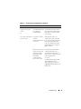
Operating System
Table 1-1 provides an overview of the supported operating systems. See your
operating system documentation for a complete list of features.
NOTE: Some of the core services are common to all the operating systems.
Table 1-1.
Windows Operating System Features
Windows Server 2003 Enterprise
Edition/Windows Server 2003 R2
Enterprise Edition
Windows Server 2003 Enterprise x64
Edition/Windows Server 2003 R2
Enterprise x64 Edition
Supports up to eight nodes per cluster
Supports up to eight nodes per cluster
Supports up to 64 GB of RAM per node Supports up to 1 TB RAM per node
Cluster configuration and management Cluster configuration and management
using Configure Your Server (CYS) and using CYS and MYS wizards
Manage Your Server (MYS) wizards
Metadirectory Services
Metadirectory Services
NOTE: The amount of RAM supported per node also depends on your cluster platform.
NOTE: Running different operating systems in a cluster is supported only during a
rolling upgrade. You cannot upgrade to Windows Server 2003, Enterprise x64
Edition/Windows Server 2003 R2, Enterprise x64 Edition. Only a new installation is
permitted for Windows Server 2003, Enterprise x64 Edition/Windows Server 2003 R2,
Enterprise x64 Edition.
NOTE: MSCS and Network Load Balancing (NLB) features cannot coexist on the
same node, but can be used together in a multi-tiered cluster. For more information,
see the Dell High Availability Clusters website at www.dell.com/ha or the Microsoft
website at www.microsoft.com.
Introduction
9
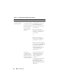
Cluster Nodes
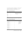
Table 1-2 lists the hardware requirements for the cluster nodes.
Table 1-2.
Cluster Node Requirements
Component
Minimum Requirement
Cluster nodes
Two to eight Dell PowerEdge™ systems running the
Windows Server 2003 operating system.
RAM
At least 256 MB of RAM installed on each cluster node for
Windows Server 2003, Enterprise Edition or
Windows Server 2003 R2, Enterprise Edition.
At least 512 MB of RAM installed on each cluster node for
Windows Server 2003, Enterprise x64 Edition, or
Windows Server 2003 R2, Enterprise x64 Edition.
NICs
At least two NICs: one NIC for the public network and
another NIC for the private network.
NOTE: It is recommended that the NICs on each public network
are identical, and that the NICs on each private network are
identical.
Internal disk
controller
One controller connected to at least two internal hard drives
for each node. Use any supported RAID controller or disk
controller.
Two hard drives are required for mirroring (RAID 1) and at
least three are required for disk striping with parity (RAID 5).
NOTE: It is strongly recommended that you use hardware-based
RAID or software-based disk-fault tolerance for the
internal drives.
HBA ports
• For clusters with Fibre Channel storage, two Fibre Channel
HBAs per node, unless the server employs an integrated or
supported dual-port Fibre Channel HBA.
• For clusters with SAS storage, one or two SAS 5/E HBAs per
node.
NOTE: Where possible, place the HBAs on separate PCI buses
to improve availability and performance. For information about
supported systems and HBAs, see Dell Cluster Configuration
Support Matrices located on the Dell High Availability Clustering
website at www.dell.com/ha.
10
Introduction
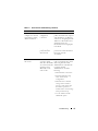
Table 1-2.
Cluster Node Requirements (continued)
Component
Minimum Requirement
iSCSI Initiator and For clusters with iSCSI storage, install the Microsoft iSCSI
NICs for iSCSI
Software Initiator (including iSCSI port driver and Initiator
Access
Service) on each cluster node.
Two iSCSI NICs or Gigabit Ethernet NIC ports per node.
NICs with a TCP/IP Off-load Engine (TOE) or iSCSI Off-load
capability may also be used for iSCSI traffic.
NOTE: Where possible, place the NICs on separate PCI buses
to improve availability and performance. For information about
supported systems and HBAs, see Dell Cluster Configuration
Support Matrices located on the Dell High Availability Clustering
website at www.dell.com/ha.
Cluster Storage
You must attach all the nodes to a common shared system for your Dell
failover cluster solutions with Windows Server 2003. The type of storage array
and topology in which the array is deployed can influence the design of your
cluster. For example, a direct-attached SAS storage array may offer support for
two cluster nodes whereas a SAN-attached Fibre Channel or iSCSI array has
the ability to support eight cluster nodes.
A shared storage array enables data for clustered applications and services to
be stored in a common location that is accessible by each cluster node.
Although only one node can access or control a given disk volume at a
particular point in time, the shared storage array enables other nodes to gain
control of these volumes in the event that a node failure occurs. This also
helps facilitate the ability of other cluster resources, which may depend upon
the disk volume to failover to the remaining nodes.
Additionally, it is recommended that you attach each node to the shared storage
array using redundant paths. Providing multiple connections (or paths) between
the node and the storage array reduces the number of single points of failure that
could otherwise impact the availability of the clustered applications or services.
For details and recommendations related to deploying a Dell Windows Server
failover cluster solution with a particular storage array, see "Cabling Your
Cluster Hardware" section in the Dell Failover Cluster Hardware Installation
and Troubleshooting Guide for the specific storage array on the Dell Support
website at support.dell.com.
Introduction
11
Other Documents You May Need
CAUTION: The safety information that is shipped with your system provides
important safety and regulatory information. Warranty information may be
included within this document or as a separate document.
NOTE: To configure Dell blade server modules in a Dell PowerEdge cluster, see the
Using Dell Blade Servers in a Dell PowerEdge High Availability Cluster document
located on the Dell Support website at support.dell.com.
•
The Dell Windows Server Failover Cluster Hardware Installation and
Troubleshooting Guide provides information on specific configuration
tasks that enable you to deploy the shared storage for your cluster.
•
The Dell Cluster Configuration Support Matrices lists the Dell-validated
hardware, firmware, and software components for a Windows Server
2003 failover cluster environment.
•
The Rack Installation Guide included with your rack solution describes
how to install your system into a rack.
•
The Getting Started Guide provides an overview to initially set up your system.
•
The HBA documentation provides installation instructions for the HBAs.
•
Systems management software documentation describes the features,
requirements, installation, and basic operation of the software.
•
Operating system documentation describes how to install (if necessary),
configure, and use the operating system software.
•
Documentation for any components you purchased separately provides
information to configure and install those options.
•
The Dell PowerVault™ tape library documentation provides information
for installing, troubleshooting, and upgrading the tape library.
•
Any other documentation that came with your server and storage system.
•
Updates are sometimes included with the system to describe changes to
the system, software, and/or documentation.
NOTE: Always read the updates first because they often supersede
information in other documents.
•
12
Release notes or readme files may be included to provide last-minute
updates to the system or documentation, or advanced technical reference
material intended for experienced users or technicians.
Introduction
Preparing Your Systems for Clustering
CAUTION: Only trained service technicians are authorized to remove and access
any of the components inside the system. See the safety information shipped with
your system for complete information about safety precautions, working inside the
computer, and protecting against electrostatic discharge.
Cluster Configuration Overview
NOTE: For more information on step 1, step 2 and step 9, see "Preparing Your
Systems for Clustering" section of the Dell Failover Hardware Installation and
Troubleshooting Guide for the specific storage array on the Dell Support website at
support.dell.com. For more information on step 3 to step 7 and step 10 to step 13,
see this chapter.
1 Ensure that your site can handle the cluster’s power requirements.
Contact your sales representative for information about your region's
power requirements.
2 Install the servers, the shared storage array(s), and the interconnect
switches (example: in an equipment rack), and ensure that all these
components are powered on.
3 Deploy the operating system (including any relevant service pack and
hotfixes), network adapter drivers, and storage adapter drivers (including
MPIO drivers) on each of the servers that will become cluster nodes.
Depending on the deployment method that is used, it may be necessary to
provide a network connection to successfully complete this step.
NOTE: You can record the Cluster configuration and Zoning configuration
(if relevant) to the Cluster Data Form and Zoning Configuration Form,
respectively to help in planning and deployment of your cluster. For more
information, see "Cluster Data Form" and "Zoning Configuration Form" of
Dell Failover Cluster Hardware Installation and Troubleshooting Guide for the
specific storage array on the Dell Support website at support.dell.com.
4 Establish the physical network topology and the TCP/IP settings for
network adapters on each server node to provide access to the cluster
public and private networks.
Preparing Your Systems for Clustering
13
5 Configure each server node as a member server in the same
Windows Active Directory Domain.
NOTE: It may also be possible to have cluster nodes serve as Domain
controllers. For more information, see “Selecting a Domain Model”.
6 Establish the physical storage topology and any required storage network
settings to provide connectivity between the storage array and the servers
that will be configured as cluster nodes. Configure the storage system(s) as
described in your storage system documentation.
7 Use storage array management tools to create at least one logical unit
number (LUN). The LUN is used as a cluster quorum disk for Windows
Server 2003 Failover cluster and as a witness disk for Windows Server 2008
Failover cluster. Ensure that this LUN is presented to the servers that will
be configured as cluster nodes.
NOTE: It is highly recommended that you configure the LUN on a single node,
for security reasons, as mentioned in step 8 when you are setting up the
cluster. Later, you can configure the LUN as mentioned in step 9 so that other
cluster nodes can access it.
8 Select one of the servers and form a new failover cluster by configuring the
cluster name, cluster management IP, and quorum resource.
NOTE: For Windows Server 2008 Failover Clusters, run the Cluster Validation
Wizard to ensure that your system is ready to form the cluster.
9 Join the remaining node(s) to the failover cluster.
10 Configure roles for cluster networks. Take any network interfaces that are
used for iSCSI storage (or for other purposes outside of the cluster) out of
the control of the cluster.
11 Test the failover capabilities of your new cluster.
NOTE: For Windows Server 2008 Failover Clusters, the Cluster Validation
Wizard may also be used.
12 Configure highly-available applications and services on your failover
cluster. Depending on your configuration, this may also require providing
additional LUNs to the cluster or creating new cluster resource groups.
Test the failover capabilities of the new resources.
13 Configure client systems to access the highly-available applications and
services that are hosted on your failover cluster.
14
Preparing Your Systems for Clustering
Installation Overview
This section provides installation overview procedures for configuring a
cluster running the Microsoft® Windows Server® 2003 operating system.
NOTE: Storage management software may vary and use different terms than those
in this guide to refer to similar entities. For example, the terms "LUN" and "Virtual
Disk" are often used interchangeably to designate an individual RAID volume that is
provided to the cluster nodes by the storage array.
1 Ensure that the cluster meets the requirements as described in "Cluster
Configuration Overview."
2 Select a domain model that is appropriate for the corporate network and
operating system.
See "Selecting a Domain Model" on page 19.
3 Reserve static IP addresses for the cluster resources and components,
including:
•
Public network
•
Private network
•
Cluster virtual servers
Use these IP addresses when you install the Windows® operating system
and MSCS.
4 Configure the internal hard drives.
See "Configuring Internal Drives in the Cluster Nodes" on page 20.
5 Install and configure the Windows operating system.
The Windows operating system must be installed on all of the nodes. Each
node must have a licensed copy of the Windows operating system, and a
Certificate of Authenticity.
See "Installing and Configuring the Microsoft Windows
Operating System" on page 20.
Preparing Your Systems for Clustering
15
6 Install or update the storage connection drivers.
For more information on connecting your cluster nodes to a shared storage
array, see "Preparing Your Systems for Clustering" in the Dell Failover
Cluster Hardware Installation and Troubleshooting Guide that
corresponds to your storage array. For more information on the
corresponding supported adapters and driver versions, see Dell Cluster
Configuration Support Matrices located on the Dell High Availability
Clustering website at www.dell.com/ha.
7 Install and configure the storage management software.
See the documentation included with your storage system or available at
the Dell Support website at support.dell.com.
8 Configure the hard drives on the shared storage system(s).
See "Preparing Your Systems for Clustering" in the Dell Failover Cluster
Hardware Installation and Troubleshooting Guide corresponding to your
storage array.
9 Configure the MSCS software.
See "Configuring Your Failover Cluster" on page 29.
10 Verify cluster functionality. Ensure that:
•
The cluster components are communicating properly.
•
MSCS is started.
See "Verifying Cluster Functionality" on page 33.
11 Verify cluster resource availability.
Use Cluster Administrator to check the running state of each resource
group. See "Verifying Cluster Resource Availability."
The following subsections provide detailed information about some steps in
the "Installation Overview" that is specific to the Windows Server 2003
operating system.
16
Preparing Your Systems for Clustering
Selecting a Domain Model
On a cluster running the Microsoft Windows operating system, all nodes
must belong to a common domain or directory model. The following
configurations are supported:
•
All nodes are member servers in an Active Directory® domain.
•
All nodes are domain controllers in an Active Directory domain.
•
At least one node is a domain controller in an Active Directory and the
remaining nodes are member servers.
Configuring the Nodes as Domain Controllers
If a node is configured as a domain controller, client system access to its
cluster resources can continue even if the node cannot contact other domain
controllers. However, domain controller functions can cause additional
overhead, such as log on, authentication, and replication traffic.
If a node is not configured as a domain controller and the node cannot contact
a domain controller, the node cannot authenticate client system requests.
Configuring Internal Drives in the Cluster Nodes
If your system uses a hardware-based RAID solution and you have added new
internal hard drives to your system, or you are setting up the RAID configuration
for the first time, you must configure the RAID array using the RAID controller’s
BIOS configuration utility before installing the operating system.
For the best balance of fault tolerance and performance, use RAID 1. See the
RAID controller documentation for more information on RAID configurations.
NOTE: If you are not using a hardware-based RAID solution, use the Microsoft
Windows Disk Management tool to provide software-based redundancy.
Preparing Your Systems for Clustering
17
Installing and Configuring the Microsoft
Windows Operating System
NOTE: Windows standby mode and hibernation mode are not supported in cluster
configurations. Do not enable either mode.
1 Ensure that the cluster configuration meets the requirements listed in
"Cluster Configuration Overview."
2 Cable the hardware.
NOTE: Do not connect the nodes to the shared storage systems yet.
For more information on cabling your cluster hardware and the storage
array that you are using, see "Cabling Your Cluster Hardware" in the
Dell Failover Cluster Hardware Installation and Troubleshooting Guide
for the specific storage array on the Dell Support website at
support.dell.com.
3 Install and configure the Windows Server 2003 operating system with the
latest service pack on each node.
For more information about the latest supported service pack, see
Dell Cluster Configuration Support Matrices located on the Dell High
Availability Clustering website at www.dell.com/ha.
4 Ensure that the latest supported version of network adapter drivers is
installed on each cluster node.
5 Configure the public and private network adapter interconnects in each
node, and place the interconnects on separate IP subnetworks using static
IP addresses. See "Configuring Windows Networking" on page 22.
For information on required drivers, see Dell Cluster Configuration
Support Matrices located on the Dell High Availability Clustering website
at www.dell.com/ha.
6 Shut down both nodes and connect each node to the shared storage.
For more information on cabling your cluster hardware and the storage
array that you are using, see "Cabling Your Cluster Hardware" in the
Dell Failover Cluster Hardware Installation and Troubleshooting Guide
for the specific storage array on the Dell Support website at
support.dell.com.
7 If required, configure the storage software.
18
Preparing Your Systems for Clustering
8 Reboot node 1.
9 From node 1, write the disk signature and then partition, format, and
assign drive letters and volume labels to the hard drives in the storage
system using the Windows Disk Management application.
For more information, see "Preparing Your Systems for Clustering" in the
Dell Failover Cluster Hardware Installation and Troubleshooting Guide
for the specific storage array on the Dell Support website at
support.dell.com.
10 On node 1, verify disk access and functionality on all shared disks.
11 Shut down node 1.
12 Verify disk access by performing the following steps on the other node:
a
Turn on the node.
b
Modify the drive letters to match the drive letters on node 1.
This procedure allows the Windows operating system to mount the
volumes.
c
Close and reopen Disk Management.
d
Verify that Windows can see the file systems and the volume labels.
13 Turn on node 1.
14 Install and configure the Cluster Service.
See "Configuring Microsoft Cluster Service (MSCS) With Windows
Server 2003" on page 29.
15 Install and set up the application programs (optional).
16 Enter the cluster configuration information on the Cluster Data Form
provided as an Appendix in the Dell Failover Cluster Hardware Installation
and Troubleshooting Guide for your corresponding storage array (optional).
Preparing Your Systems for Clustering
19
Configuring Windows Networking
You must configure the public and private networks in each node before you
install MSCS. The following subsections introduce you to some procedures
necessary for the networking prerequisites.
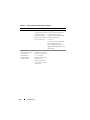
Assigning Static IP Addresses to Cluster Resources and Components
A static IP address is an Internet address that a network administrator assigns
exclusively to a system or a resource. The address assignment remains in
effect until it is changed by the network administrator.
The IP address assignments for the cluster’s public LAN segments depend on
the environment’s configuration. Configurations running the Windows
operating system require static IP addresses assigned to hardware and
software applications in the cluster, as listed in Table 2-1.
Table 2-1.
Applications and Hardware Requiring IP Address Assignments
Application/Hardware
Description
Cluster IP address
The cluster IP address is used for cluster management
and must correspond to the cluster name. Because each
server has at least two network adapters, the minimum
number of static IP addresses required for a cluster
configuration is two (one for public network and one for
the public network). Additional static IP addresses are
required when MSCS is configured with application
programs that require IP addresses, such as file sharing.
Cluster-aware
These applications include Microsoft SQL Server,
applications running on Enterprise Edition, Microsoft Exchange Server, and
the cluster
Internet Information Server (IIS). For example,
Microsoft SQL Server, Enterprise Edition requires at
least one static IP address for the virtual server
(Microsoft SQL Server does not use the cluster's IP
address). Also, each IIS Virtual Root or IIS Server
instance configured for failover needs a unique static
IP address.
20
Preparing Your Systems for Clustering
Table 2-1.
Applications and Hardware Requiring IP Address Assignments (continued)
Application/Hardware
Description
Cluster node network
adapters
For cluster operation, two network adapters are required:
one for the public network (LAN/WAN) and another for
the private network (sharing heartbeat information
between the nodes).
For more information on cabling your cluster hardware
and the storage array that you are using, see "Cabling Your
Cluster Hardware" in the Dell Failover Cluster Hardware
Installation and Troubleshooting Guide for the specific
storage array on the Dell Support website at
support.dell.com.
NOTE: To ensure operation during a DHCP server failure,
use static IP addresses.
Configuring IP Addresses for the Private Network
Use the static IP address assignments for the network adapters used for the
private network (cluster interconnect).
NOTE: The IP addresses in Table 2-2 are used as examples only.
Table 2-2.
Examples of IP Address Assignments
Usage
Cluster Node 1
Cluster Node 2
Public network static IP address
(for client and domain controller
communications)
192.168.1.101
192.168.1.102
Public network subnet mask
255.255.255.0
255.255.255.0
Default gateway
192.168.1.1
192.168.1.1
WINS servers
Primary
192.168.1.11
Primary
192.168.1.11
Secondary
192.168.1.12
Secondary
192.168.1.12
Primary
192.168.1.21
Primary
192.168.1.21
Secondary
192.168.1.22
Secondary
192.168.1.22
DNS servers
Preparing Your Systems for Clustering
21
Table 2-2.
Examples of IP Address Assignments (continued)
Usage
Cluster Node 1
Cluster Node 2
Private network static IP address
10.0.0.1
cluster interconnect (for node-to-node
communications)
10.0.0.2
Private network subnet mask
255.255.255.0
255.255.255.0
NOTE: Do not configure Default Gateway, NetBIOS, WINS, and DNS on the private
network. If you are running Windows Server 2003, disable NetBIOS on the
private network.
If multiple cluster interconnect network adapters are connected to a network
switch, ensure that all of the private network’s network adapters have a
unique address. You can continue the IP address scheme in Table 2-2 with
10.0.0.3, 10.0.0.4, and so on for the private network’s network adapters or
network adapter teams of the other clusters connected to the same switch.
You can improve fault tolerance by using network adapters that support
adapter teaming or by having multiple LAN segments. To avoid
communication problems, do not use dual-port network adapters for the
cluster interconnect.
NOTE: NIC teaming is supported only on a public network, not on a private network.
Creating Separate Subnets for the Public and Private Networks
The public and private network’s network adapters installed in the same
cluster node must reside on separate IP subnetworks. Therefore, the private
network used to exchange heartbeat information between the nodes must
have a separate IP subnet or a different network ID than the public network,
which is used for client connections.
22
Preparing Your Systems for Clustering
Setting the Network Interface Binding Order for Clusters Running
Windows Server 2003
1 Click the Start button, select Control Panel, and double-click
Network Connections.
2 Click the Advanced menu, and then click Advanced Settings.
The Advanced Settings window appears.
3 In the Adapters and Bindings tab, ensure that the Public connection is at
the top of the list and followed by the Private connection.
To change the connection order:
a
Click Public or Private.
b
Click the up-arrow or down-arrow to move the connection to the top
or bottom of the Connections box.
c
Click OK.
d
Close the Network Connections window.
Dual-Port Network Adapters and Adapter Teams in the Private Network
Dual-port network adapters and network adapter teams are not supported in
the private network. They are supported only in the public network.
Verifying Communications Between Nodes
1 Open a command prompt on each cluster node.
2 At the prompt, type:
ipconfig /all
3 Press <Enter>.
All known IP addresses for each local server appear on the screen.
4 Issue the ping command from each remote system.
Ensure that each local server responds to the ping command. If the IP
assignments are not set up correctly, the nodes may not be able to
communicate with the domain. For more information, see "Troubleshooting"
on page 63.
Preparing Your Systems for Clustering
23
Configuring the Internet Connection Firewall
The Windows Server 2003 operating system includes an enhanced Internet
Connection Firewall that can be configured to block incoming network traffic to
a PowerEdge system. To prevent the Internet Connection Firewall from
disrupting cluster communications, additional configuration settings are required
for PowerEdge systems that are configured as cluster nodes in an MSCS cluster.
Certain network communications are necessary for cluster operations, for
applications and services hosted by the cluster, and for clients accessing those
services. If the Internet Connection Firewall is enabled on the cluster nodes,
install and run the Security Configuration Wizard and then configure access
for the cluster service and for any applications or services hosted by the
cluster and the operating system.
See the following Microsoft Knowledge Base articles located at the Microsoft
Support website at support.microsoft.com for more information:
•
KB883398 - Internet Connection Firewall
•
KB832017 - Network ports used by the Windows Server 2003
operating system
Installing the Storage Connection Ports and Drivers
Ensure that an appropriate storage connection exists on the nodes before you
attach each node to the shared storage array. Also ensure that the cluster nodes
have a complimentary technology that enables proper interaction between
the nodes and shared Fibre Channel, SAS, or iSCSI storage array. You may
also require operating system drivers and Multipath Input/Output (MPIO)
drivers to ensure proper interaction between the cluster nodes and the shared
storage array.
For more information, see "Preparing Your Systems for Clustering" in the Dell
Failover Cluster Hardware Installation and Troubleshooting Guide for the
specific storage array on the Dell Support website at support.dell.com.
24
Preparing Your Systems for Clustering
Installing and Configuring the Shared Storage
System
The shared storage array consists of disk volumes that are used in your cluster.
The management software for each supported shared storage array provides a
way to create disk volumes and assigns these volumes to all the nodes in your
cluster.
For more information, see "Preparing Your Systems for Clustering" section in
the Dell Failover Cluster Hardware Installation and Troubleshooting Guide for
your specific storage array on the Dell Support website at support.dell.com.
Assigning Drive Letters and Mount Points
A mount point is a drive attached to an empty folder on an NTFS volume.
A mount point drive functions the same as a normal drive, but is assigned a
label or name instead of a drive letter. Using mount points, a cluster can
support more shared disks than the number of available drive letters.
The cluster installation procedure does not automatically add the mount
point into the disks managed by the cluster. To add the mount point to the
cluster, create a physical disk resource in the cluster resource group for each
mount point. Ensure that the new physical disk resource is in the same cluster
resource group and is dependent on the root disk.
NOTE: Mount points are only supported in MSCS on the Windows Server 2003
operating system. When mounting a drive to an NTFS volume, do not create mount
points from the quorum resource or between the clustered disks and the local
disks. Mount points must be in the same cluster resource group and must be
dependent on the root disk.
NOTICE: If the disk letters are manually assigned from the remaining node(s), the
shared disks are simultaneously accessible from both nodes. To ensure file system
integrity and prevent possible data loss before you install the MSCS software,
prevent any I/O activity to the shared drives by performing this procedure on one
node at a time, and ensure that all other nodes are turned off.
The number of drive letters required by individual servers in a cluster may vary.
It is recommended that the shared drives be named in reverse alphabetical
order beginning with the letter z.
Preparing Your Systems for Clustering
25
To assign drive letters, create mount points, and format the disks on the
shared storage system:
1 Turn off the remaining node(s) and open Disk Management on node 1.
2 Allow Windows to enter a signature on all new physical or logical drives.
NOTE: Do not create dynamic disks on your hard drives.
3 Locate the icon for the first unnamed, unformatted drive on the shared
storage system.
4 Right-click the icon and select Create from the submenu.
If the unformatted drives are not visible, verify the following:
•
The HBA driver is installed.
•
The storage system is properly cabled to the servers.
•
The LUNs and hosts are assigned through a storage group (if Access
Control is enabled).
5 In the dialog box, create a partition the size of the entire drive (the
default) and then click OK.
NOTE: The MSCS software allows only one node to access a logical drive at
a time. If a logical drive is partitioned into multiple disks, only one node is able
to access all the partitions for that logical drive. If a separate disk is to be
accessed by each node, two or more logical drives must be present in the
storage system.
6 Click Yes to confirm the partition.
7 With the mouse pointer on the same icon, right-click and select
Change Drive Letter and Path from the submenu.
8 Assign a drive letter to an NTFS volume or create a mount point.
To assign a drive letter to an NTFS volume:
26
a
Click Edit and select the letter you want to assign to the drive
(for example, Z).
b
Click OK.
c
Go to step 9.
Preparing Your Systems for Clustering
To create a mount point:
a
Click Add.
b
Click Mount in the following empty NTFS folder.
c
Type the path to an empty folder on an NTFS volume, or click Browse
to locate it.
d
Click OK.
e
Go to step 9.
9 Click Yes to confirm the changes.
10 Right-click the drive icon again and select Format from the submenu.
11 Under Volume Label, enter a descriptive name for the new volume; for
example, Disk_Z or Email_Data.
12 In the dialog box, change the file system to NTFS, select Quick Format,
and click Start.
NOTE: The NTFS file system is required for shared-disk resources under MSCS.
13 Click OK at the warning.
14 Click OK to acknowledge that the format is complete.
15 Click Close to close the dialog box.
16 Repeat step 3 through step 15 for each remaining drive.
17 Close Disk Management.
18 Turn off node 1.
19 Perform the following steps on the remaining node(s), one at a time:
a
Turn on the node.
b
Open Disk Management.
c
Assign the drive letters to the drives.
This procedure allows Windows to mount the volumes.
d
Reassign the drive letter, if necessary.
To reassign the drive letter, repeat step 7 through step 9.
e
Turn off the node.
Preparing Your Systems for Clustering
27
Configuring Hard Drive Letters When Using Multiple Shared
Storage Systems
Before installing MSCS, ensure that both nodes have the same view of the
shared storage systems. Because each node has access to hard drives that are
in a common storage array, each node must have identical drive letters
assigned to each hard drive. Your cluster can access more than 22 volumes
using volume mount points in Windows Server 2003.
NOTE: Drive letters A through D are reserved for the local system.
To ensure that hard drive letter assignments are identical:
1 Ensure that your cables are attached to the shared storage devices in the
proper sequence.
You can view all of the storage devices using Windows Server 2003 Disk
Management.
2 To maintain proper drive letter assignments, ensure that each storage
connection port is enumerated by each node and is connected to the same
RAID controller, storage processor, or SAN switch.
For more information on the location of the RAID controllers or storage
processors on your shared storage array, see "Cabling Your Cluster
Hardware" in the Dell Failover Cluster Hardware Installation and
Troubleshooting Guide for the specific storage array on the Dell Support
website at support.dell.com.
3 Go to Formatting and Assigning Drive Letters and Volume Labels to the Disks.
Formatting and Assigning Drive Letters and Volume Labels to the Disks
1 Shut down all the cluster nodes except node 1.
2 Format the disks, assign the drive letters and volume labels on node 1 by
using the Windows Disk Management utility.
For example, create volumes labeled "Volume Y" for disk Y and "Volume Z"
for disk Z.
3 Shut down node 1 and perform the following steps on the remaining
node(s), one at a time:
28
a
Turn on the node.
b
Open Disk Management.
Preparing Your Systems for Clustering
c
Assign the drive letters for the drives.
This procedure allows Windows to mount the volumes.
d
Reassign the drive letter, if necessary.
To reassign the drive letter:
e
•
With the mouse pointer on the same icon, right-click and select
Change Drive Letter and Path from the submenu.
•
Click Edit, select the letter you want to assign the drive (for
example, Z), and then click OK.
•
Click Yes to confirm the changes.
Power down the node.
If the cables are connected properly, the drive order is the same as is on
each node, and the drive letter assignments of all the cluster nodes follow
the same order as on node 1. The volume labels can also be used to
double-check the drive order by ensuring that the disk with volume label
"Volume Z" is assigned to drive letter Z and so on for each disk on each
node. Assign drive letters on each of the shared disks, even if the disk
displays the drive letter correctly.
For more information about the storage array management software, see your
storage array documentation located on the Dell Support website at
support.dell.com.
Configuring Your Failover Cluster
MSCS is an integrated service in Windows Server 2003 which is required for
configuring your failover cluster. MSCS performs the basic cluster
functionality, which includes membership, communication, and failover
management. When MSCS is installed properly, the service starts on each
node and responds automatically in the event that one of the nodes fails or
goes offline. To provide application failover for the cluster, the MSCS
software must be installed on each cluster node. For more information, see
"Understanding Your Failover Cluster" on page 37.
Preparing Your Systems for Clustering
29
Configuring Microsoft Cluster Service (MSCS) With
Windows Server 2003
The cluster setup files are automatically installed on the system disk.
To create a new cluster:
1 Click the Start button, select Programs→Administrative Tools→Cluster
Administrator.
2 From the File menu, select Open Connection.
3 In the Action box of the Open Connection to Cluster, select Create new
cluster.
The New Server Cluster Wizard window appears.
4 Click Next to continue.
5 Follow the procedures in the wizard, and then click Finish.
6 Add the additional node(s) to the cluster.
a
Turn on the remaining node(s).
b
Click the Start button, select Programs→Administrative Tools, and
then double-click Cluster Administrator.
c
From the File menu, select Open Connection.
d
In the Action box of the Open Connection to Cluster, select
Add nodes to cluster.
e
In the Cluster or server name box, type the name of the cluster or click
Browse to select an available cluster from the list, and then click OK.
The Add Nodes Wizard window appears.
If the Add Nodes Wizard does not generate a cluster feasibility error,
go to step f.
If the Add Nodes Wizard generates a cluster feasibility error, go to
"Adding Cluster Nodes Using the Advanced Configuration Option."
30
f
Click Next to continue.
g
Follow the procedures in the wizard and click Finish.
Preparing Your Systems for Clustering
Adding Cluster Nodes Using the Advanced Configuration Option
If you are adding additional nodes to the cluster using the Add Nodes wizard
and the nodes are not configured with identical internal storage devices, the
wizard may generate one or more errors while checking cluster feasibility in the
Analyzing Configuration menu. If this situation occurs, select Advanced
Configuration Option in the Add Nodes wizard to add the nodes to the cluster.
To add the nodes using the Advanced Configuration Option:
1 From the File menu in Cluster Administrator, select Open Connection.
2 In the Action box of the Open Connection to Cluster, select Add nodes
to cluster. and then click OK.
The Add Nodes Wizard window appears.
3 Click Next.
4 In the Select Computers menu, click Browse.
5 In the Enter the object names to select (examples), type the names of one
to seven systems to add to the cluster, with each system name separated by
a semicolon.
6 Click Check Names.
The Add Nodes Wizard verifies and underlines each valid system name.
7 Click OK.
8 In the Select Computers menu, click Add.
9 In the Advanced Configuration Options window, click Advanced
(minimum) configuration, and then click OK.
10 In the Add Nodes window, click Next.
11 In the Analyzing Configuration menu, Cluster Administrator analyzes the
cluster configuration.
If Cluster Administrator discovers a problem with the cluster
configuration, a warning icon appears in the Checking cluster feasibility
window. Click the plus ("+") sign to review any warnings, if needed.
12 Click Next to continue.
Preparing Your Systems for Clustering
31
13 In the Password field of the Cluster Service Account menu, type the
password for the account used to run the Cluster Service, and click Next.
The Proposed Cluster Configuration menu appears with a summary with
the configuration settings for your cluster.
14 Click Next to continue.
The new systems (hosts) are added to the cluster. When completed,
Tasks completed appears in the Adding Nodes to the Cluster menu.
NOTE: This process may take several minutes to complete.
15 Click Next to continue.
16 In the Completing the Add Nodes Wizard window, click Finish.
Verifying Cluster Readiness
To ensure that your server and storage systems are ready for MSCS
installation, ensure that these systems are functioning correctly and verify the
following:
•
All cluster servers are able to log on to the same domain.
•
The shared disks are partitioned and formatted, and the same drive letters that
reference logical drives on the shared storage system are used on each node.
All IP addresses and network names for each cluster node are communicating
with each other and the public network
Installing Applications in the Cluster Group
The Cluster Group contains a network name and IP address resource, which
is used to manage the cluster. Because the Cluster Group is dedicated to
cluster management and for best cluster performance, it is recommended
that you do not install applications in this group.
Installing the Quorum Resource
When you install a Windows Server 2003 cluster, the installation wizard
automatically selects an NTFS disk as the quorum resource for you, which
you can modify later. When you complete the procedures in the wizard, you
can select another disk for the quorum using Cluster Administrator.
To prevent quorum resource corruption, it is recommended that you do not
place applications or data on the disk.
32
Preparing Your Systems for Clustering
Creating a LUN for the Quorum Resource
It is recommended that you create a separate LUN—approximately 1 GB in
size—for the quorum resource.
When you create the LUN for the quorum resource:
•
Format the LUN with NTFS.
•
Use the LUN exclusively for your quorum logs.
•
Do not store any application data or user data on the quorum resource.
•
To easily identify the quorum resource, it is recommended that you assign
the drive letter "Q" to the quorum resource.
NOTE: The Majority Node Set Quorum types for Windows Server 2003 are not
supported.
Preventing Quorum Resource Failure
Since the quorum resource plays a crucial role in cluster operation, losing a
quorum resource causes the entire cluster to fail. To prevent cluster failure,
configure the quorum resource on a RAID volume in the shared storage system.
NOTE: It is recommend that you use a RAID level other than RAID 0, which is
commonly called striping. RAID 0 configurations provide very high performance, but
they do not provide the level of availability required for the quorum resource.
Configuring Cluster Networks Running Windows Server 2003
When you install and configure a cluster running Windows Server 2003, the
software installation wizard automatically configures all networks for mixed
(public and private) use in your cluster. You can rename a network, allow or
disallow the cluster to use a particular network, or modify the network role
using Cluster Administrator. It is recommended that you configure at least
one network for the cluster interconnect (private network) and provide
redundancy for the private network by configuring an additional network for
mixed (public and private) use. If you have enabled network adapter teaming
or are using dual-port NICs for use on your public network, you should change
the configuration for these networks to support public communications only.
Preparing Your Systems for Clustering
33
Verifying MSCS Operation
After you install MSCS, verify that the service is operating properly.
If you selected Cluster Service when you installed the operating system, see
"Obtaining More Information" on page 34.
If you did not select Cluster Service when you installed the operating system:
1 Click the Start button and select Programs→Administrative Tools, and
then select Services.
2 In the Services window, verify the following:
•
In the Name column, Cluster Service appears.
•
In the Status column, Cluster Service is set to Started.
•
In the Startup Type column, Cluster Service is set to Automatic.
Obtaining More Information
See Microsoft's online help for configuring the Cluster Service.
See "Understanding Your Failover Cluster" on page 37 for more information
on the Cluster Service.
Verifying Cluster Functionality
To verify cluster functionality, monitor the cluster network communications
to ensure that your cluster components are communicating properly with
each other. Also, verify that MSCS is running on the cluster nodes.
Verifying Cluster Resource Availability
In the context of clustering, a resource is a basic unit of failover management.
Application programs are made up of resources that are grouped together for
recovery purposes. All recovery groups, and therefore the resources that
comprise the recovery groups, must be online (or in a ready state) for the
cluster to function properly.
To verify that the cluster resources are online:
1 Start Cluster Administrator on the monitoring node.
2 Click the Start button and select Programs→Administrative Tools
(Common)→Cluster Administrator.
34
Preparing Your Systems for Clustering
Installing Your Cluster Management
Software
This section provides information on configuring and administering your
cluster using Microsoft® Cluster Administrator. Microsoft provides Cluster
Administrator as a built-in tool for cluster management.
Microsoft Cluster Administrator
Cluster Administrator is Microsoft’s tool for configuring and administering a
cluster. The following procedures describe how to run Cluster Administrator
locally on a cluster node and how to install the tool on a remote console.
Launching Cluster Administrator on a Cluster Node
Click Start→Programs→Administrative Tools→Cluster Administrator to
launch the Cluster Administrator.
Running Cluster Administrator on a Remote Console
You can administer and monitor the Cluster Service remotely by installing the
Windows Administration Tools package and Cluster Administrator on a
remote console (or management station) running the Microsoft Windows®
operating system. Cluster Administrator is part of the Administration Tools
package, which is included with the Windows Server® 2003 operating system.
The Windows Server 2003 Administrative Tools can only be installed on
systems running Windows XP (with Service Pack 1 or later) and Windows
Server 2003.
Installing Your Cluster Management Software
35
To install Cluster Administrator and the Windows Administration Tools package
on a remote console:
1 Select a system that you wish to configure as the remote console.
2 Identify the operating system that is currently running on the selected system.
3 Insert the appropriate operating system CD into the system’s CD drive:
•
Windows Server 2003, Enterprise Edition CD
•
Windows Server 2003 R2, Enterprise Edition CD 1
•
Windows Server 2003, Enterprise x64 Edition CD
•
Windows Server 2003 R2, Enterprise x64 Edition CD 1
4 Open an Explorer window, navigate to the system’s CD drive and
double-click the \i386 directory.
5 If you inserted the Windows Server 2003 R2, Enterprise Edition CD 1or the
Windows Server 2003, Enterprise Edition CD, double-click
ADMINPAK.MSI.
If you inserted the Windows Server 2003 R2, Enterprise x64 Edition CD 1
or the Windows Server 2003, Enterprise x64 Edition CD, double-click
WADMINPAK.MSI.
6 Follow the instructions on your screen to complete the installation.
Launching Cluster Administrator on a Remote Console
Perform the following steps on the remote console:
1 Ensure that the Windows Administrative Tools package was installed on
the system.
2 Click the Start button and select Programs.
3 Select Administrative Tools.
4 Select Cluster Administrator.
36
Installing Your Cluster Management Software
Understanding Your Failover Cluster
Cluster Objects
Cluster objects are the physical and logical units managed by a cluster. Each
object is associated with the following:
•
Properties that define the object and its behavior within the cluster
•
A set of cluster control codes used to manipulate the object's properties
•
A set of object management functions to manage the object through
Microsoft® Cluster Services (MSCS)
Cluster Networks
A cluster network provides a communications link between the cluster nodes
(private network), the client systems in a local area network (public network),
or a combination of the above (public-and-private network).
Preventing Network Failure
When you install MSCS, identify the public and private network segments
connected to your cluster nodes. To ensure cluster failover and noninterrupted communications, perform the following procedures:
1 Configure the private network for internal communications.
2 Configure the public network for all communications to provide a
redundant path if all of the private networks fail.
3 Configure subsequent network adapters for client system use only or for all
communications.
You can set priorities and roles of the networks when you install MSCS or
when you use the Microsoft Cluster Administrator software.
Understanding Your Failover Cluster
37
Node-to-Node Communication
If a network is configured for public (client) access only, the Cluster Service
will not use the network for internal node-to-node communications. If all of
the networks that are configured for private (or mixed) communication fail,
the nodes cannot exchange information and one or more nodes will terminate
MSCS and temporarily stop participating in the cluster.
Network Interfaces
You can use Cluster Administrator or another cluster management
application to view the state of all cluster network interfaces.
Cluster Nodes
A cluster node is a system in a cluster running the Microsoft Windows®
operating system and MSCS.
Each node in a cluster:
•
Attaches to one or more cluster storage devices that store all of the cluster's
configuration and resource data; nodes have access to all cluster
configuration data
•
Communicates with the other nodes through network adapters
•
Is aware of systems that join or leave the cluster
•
Is aware of the resources that are running on each node
•
Is grouped with the remaining nodes under a common cluster name, which
is used to access and manage the cluster
Table 4-1 defines states of a node during cluster operation
Table 4-1.
State
Node States and Definitions
Definition
Down
The node is not actively participating in cluster operations.
Joining
The node is becoming an active participant in the cluster operations.
Paused
The node is actively participating in cluster operations but cannot
take ownership of resource groups or bring resources online.
Up
The node is actively participating in all cluster operations, including
hosting cluster groups.
Unknown
The node state cannot be determined.
38
Understanding Your Failover Cluster
When MSCS is configured on a node, the administrator chooses whether
that node forms its own cluster or joins an existing cluster. When MSCS is
started, the node searches for other active nodes on networks that are enabled
for internal cluster communications.
Forming a New Cluster
MSCS maintains a current copy of the cluster database on all active nodes.
If a node cannot join a cluster, the node attempts to gain control of the
quorum resource and form a cluster. The node uses the recovery logs in the
quorum resource to update its cluster database.
Joining an Existing Cluster
A node can join a cluster if it can communicate with another active node in
the cluster. When a node joins a cluster, the node is updated with the latest
copy of the cluster database. MSCS validates the node's name, verifies version
compatibility, and the node joins the cluster.
Cluster Resources
A cluster resource is any physical or logical component that can be:
•
Brought online and taken offline
•
Managed in a cluster
•
Hosted by one managed system at a time
When MSCS makes a resource request through a dynamic link library (DLL),
the Resource Monitor checks and controls the resource's state.
Setting Resource Properties
Using the resource Properties dialog box, you can perform the following tasks:
•
View or change the resource name, description, and possible owners.
•
Assign a separate resource memory space.
•
View the resource type, group ownership, and resource state.
•
View which node currently owns the resource.
•
View pre-existing dependencies and modify resource dependencies.
•
Restart a resource and configure the resource settings (if required).
Understanding Your Failover Cluster
39
•
Check the online state of the resource by configuring the Looks Alive
(general check of the resource) and Is Alive (detailed check of the resource)
polling intervals in MSCS.
•
Specify the time requirement for resolving a resource in a pending state
(Online Pending or Offline Pending) before MSCS places the resource in
Offline or Failed status.
•
Set specific resource parameters.
The General, Dependencies, and Advanced tabs are the same for every
resource; however, some resource types support additional tabs.
NOTE: Do not update cluster object properties on multiple nodes simultaneously.
See the MSCS online documentation for more information.
Resource Dependencies
MSCS uses the resource dependencies list when bringing resources online
and offline. For example, if a group with a physical disk and a file share is
brought online together, the physical disk containing the file share must be
brought online before the file share. Table 4-2 shows resources and their
dependencies.
NOTE: You must configure the required dependencies before you create the resource.
Table 4-2.
Cluster Resources and Required Dependencies
Resource
Required Dependencies
File share
Network name (only if configured as a distributed file system
[DFS] root)
IP address
None
Network name IP address that corresponds to the network name
Physical disk
40
None
Understanding Your Failover Cluster
Setting Advanced Resource Properties
By using the Advanced tab in the Properties dialog box, you can perform the
following tasks:
•
Restart a resource or allow the resource to fail.
See "Adjusting the Threshold and Period Values" on page 43 for more
information.
•
Adjust the Looks Alive or Is Alive parameters.
•
Select the default number for the resource type.
•
Specify the time parameter for a resource in a pending state.
Resource Parameters
The Parameters tab in the Properties dialog box is available for most
resources. Table 4-3 shows each resource and its configurable parameters.
Table 4-3.
Resources and Configurable Parameters
Resource
Configurable Parameters
File share
Share permissions and number of simultaneous users
Share name (clients systems detect the name in their browse or
explore lists)
Share comment
Shared file path
IP address
IP address
Subnet mask
Network parameters for the IP address resource (specify the
correct network)
Network name Cluster name or virtual server
Physical disk
Hard drive for the physical disk resource (cannot be changed after
the resource is created)
Understanding Your Failover Cluster
41
Quorum Resource
Normally, the quorum resource is a common cluster resource that is accessible
by all of the nodes. The quorum resource—typically a physical disk on a
shared storage system—maintains data integrity, cluster unity, and cluster
operations.
When the cluster is formed or when the nodes fail to communicate, the
quorum resource guarantees that only one set of active communicating nodes
is allowed to form a cluster. If a node fails and the node containing the
quorum resource is unable to communicate with the remaining nodes, MSCS
shuts down the node that does not control the quorum resource. If a node
fails, the configuration database helps the cluster recover a failed resource or
recreates the cluster in its current configuration.
The shared physical disk is the only resource supported by the solution that
can act as a quorum resource.
NOTE: The Majority Node Set Quorum resource type is not supported.
Additionally, the quorum resource ensures cluster integrity. MSCS uses the
quorum resource’s recovery logs to update the private copy of the cluster
database in each node, thereby maintaining the correct version of the cluster
database and ensuring that the cluster is intact.
The operating system uses the quorum resource to ensure that only one set of
active, communicating nodes is allowed to operate as a cluster. A node can
form a cluster only if the node can gain control of the quorum resource.
A node can join a cluster or remain in an existing cluster only if it can
communicate with the node that controls the quorum resource.
Resource Failure
MSCS periodically launches the Resource Monitor to check if a resource is
functioning properly. Configure the Looks Alive and Is Alive polls to check
for failed resources. The Is Alive poll interval is typically longer than the
Looks Alive poll interval because MSCS requests a more thorough check of
the resource's state.
NOTE: Do not adjust the Looks Alive and Is Alive settings unless instructed to do so
by technical support.
42
Understanding Your Failover Cluster
Adjusting the Threshold and Period Values
The Threshold value determines the number of attempts to restart the
resource before the resource fails over. The Period value assigns a time
requirement for the Threshold value to restart the resource.
If MSCS exceeds the maximum number of restart attempts within the
specified time period and the failed resource has not been restarted, MSCS
considers the resource to be failed.
NOTE: See "Setting Advanced Resource Properties" to configure the Looks Alive, Is
Alive, Threshold, and Period values for a particular resource.
NOTE: Do not adjust the Threshold and Period settings unless instructed by
technical support.
Configuring Failover
You can configure a resource to affect the group and fail over an entire group
to another node when a resource fails in that group. If the number of failover
attempts exceeds the group's threshold and the resource is still in a failed
state, MSCS attempts to restart the resource after a period of time specified
by the resource's Retry Period On Failure property.
NOTE: Do not adjust the Retry Period On Failure settings unless instructed by
technical support.
When you configure Retry Period On Failure, use the following guidelines:
•
Select a unit value of minutes rather than milliseconds (the default value
is milliseconds).
•
Select a value that is greater than or equal to the value of the resource’s
restart period property.
Understanding Your Failover Cluster
43
Resource Dependencies
A dependent resource requires another resource to operate. Table 4-4
describes resource dependencies.
Table 4-4.
Resource Dependencies
Term
Definition
Dependent
resource
A resource that depends on other resources.
Dependency
A resource on which another resource depends.
Dependency tree A series of dependency relationships or hierarchy.
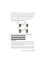
The following rules apply to a dependency tree:
• A dependent resource and its dependencies must be in the
same group.
• A dependent resource is taken offline before its dependencies
and brought online after its dependencies, as determined by
the dependency hierarchy.
Creating a New Resource
Before you add a resource to your cluster solution, verify that the following
conditions exist in your cluster:
•
The type of resource is either a standard resource provided with MSCS or a
custom resource provided by Microsoft or a third party vendor.
•
A group that will contain the resource already exists within your cluster.
•
All dependent resources have been created.
•
A separate Resource Monitor exists (recommended for any resource that
has caused problems in the past).
To create a new resource:
1 Click the Start button and select Programs→Administrative
Tools→Cluster Administrator.
The Cluster Administrator window appears.
2 In the console tree, double-click the Groups folder.
3 Select the group to which you want the resource to belong.
44
Understanding Your Failover Cluster
4 On the File menu, point to New and click Resource.
5 In the New Resource wizard, type the appropriate information in the
Name and Description fields and select the appropriate Resource type and
Group for the new resource.
6 Click Next.
7 Add or remove possible owners of the resource and click Next.
The New Resource window appears with Available resources and Resource
dependencies selections.
•
To add dependencies, under Available resources, select a resource, and
then click Add.
•
To remove dependencies, under Resource dependencies, select a
resource, and then click Remove.
8 Repeat step 7 for all resource dependencies and click Finish.
9 Set the resource properties.
For more information about setting resource properties, see the MSCS
online help.
Deleting a Resource
1 Click the Start button and select Programs→Administrative
Tools→Cluster Administrator.
The Cluster Administrator window appears.
2 In the console tree, double-click the Resources folder.
3 In the details pane, select the resource that you want to remove.
4 In the File menu, click Offline.
The resource must be taken offline before it can be deleted.
5 In the File menu, click Delete.
When you delete a resource, Cluster Administrator deletes all of the
resources that are dependent on the deleted resource.
Understanding Your Failover Cluster
45
File Share Resource Type
If you want to use your cluster solution as a high-availability file server, select
one of the following types of file share for your resource:
•
Basic file share — Publishes a file folder to the network under a single
name.
•
Share subdirectories — Publishes several network names—one for each file
folder and all of its immediate subfolders. This method is an efficient way
to create large numbers of related file shares on a file server.
•
Distributed File System (DFS) root — Creates a resource that manages a
stand-alone DFS root. Fault-tolerant DFS roots cannot be managed by
this resource. A DFS root file share resource has required dependencies on
a network name and an IP address. The network name can be either the
cluster name or any other network name for a virtual server.
Configuring Active and Passive Cluster Nodes
Active nodes process application requests and provide client services. Passive
nodes are backup nodes that ensure that client applications and services are
available if a hardware or software failure occurs. Cluster configurations may
include both active and passive nodes.
NOTE: Passive nodes must be configured with appropriate processing power and
storage capacity to support the resources that are running on the active nodes.
Your cluster solution supports variations of active/active (activex) and
active/passive (activex/passivex) configurations. The variable x indicates the
number of nodes that are active or passive.
Cluster solutions running the Windows Server 2003 operating system can
support up to eight nodes in multiple configurations as shown in Table 4-6.
An active/active (activex) configuration contains virtual servers running
separate applications or services on each node. When an application is
running on node 1, the remaining node(s) do not have to wait for node 1 to
fail. Those node(s) can run their own cluster-aware applications (or another
instance of the same application) while providing failover for the resources on
node 1. For example, multiway failover is an active/active failover solution
because running applications from a failed node can migrate to multiple
active nodes in the cluster. However, you must ensure that adequate resources
are available on each node to handle the increased load if one node fails.
46
Understanding Your Failover Cluster
In an active/passive (activex/passivex) configuration, one or more active cluster
nodes are processing requests for a clustered application while the passive
cluster nodes only wait for the active node(s) to fail.
Table 4-5 provides a description of active/active configuration types.
Table 4-5.
Active/Active Configuration Types
Configuration Type
2
Active
3
Active Cluster Node(s)
Definition
2
The active node(s) processes requests
and provides failover for each other,
depending on node resources and
your configuration.
Active
3
Active4
4
5
Active
5
Active6
6
Active7
7
8
8
Active
Table 4-6 provides a description of some active/passive configuration types.
Table 4-6.
Active/Passive Configuration Types
Configuration Type Active Cluster Node(s) Passive Cluster Node(s) Description
Active1/Passive1
2
Active /Passive
1
1
1
2
1
Active2/Passive2
2
2
Active3/Passive1
3
1
3/Passive2
Active
3
2
Active4/Passive1
4
1
Active4/Passive2
4
2
5
Active /Passive
1
5
1
Active5/Passive2
5
2
Active6/Passive1
6
1
6/Passive2
Active
6
2
Active7/Passive1
7
1
The active
node(s) processes
requests while
the passive node
waits for the
active node to
fail.
Understanding Your Failover Cluster
47
Failover Policies
When implementing a failover policy, configure failback if the cluster node
lacks the resources (such as memory or processing power) to support cluster
node failures.
Windows Server 2003 Cluster Configurations
Cluster configurations running Windows Server 2003 provide the following
failover policies:
•
N (number of active nodes)+ I (number of inactive nodes) failover
•
Failover pair
•
Multiway failover
•
Failover ring
Table 4-7 provides an overview of the failover policies implemented with
Windows Server 2003. For more information, see the sections that follow this
table.
Table 4-7.
Windows Server 2003 Failover Policies
Failover
Policy
Description
Advantage
Disadvantage(s)
N+I
One or more nodes
provides backup for
multiple servers.
Highest
resource
availability.
• May not handle more than
one backup node failure.
• May not fully utilize all of
the nodes.
Failover pair Applications can fail Easy to plan the Applications on the pair
over between the two capacity of each cannot tolerate two node
nodes.
node.
failures.
Multiway
Running applications
migrate to multiple
nodes in the cluster.
Failover ring Running applications
migrate to the next
preassigned node.
48
Application load Must ensure that the
balancing.
failover nodes have ample
resources available to handle
the additional workload.
Easy to scope
node capacity
for one server
failure.
Understanding Your Failover Cluster
The next node for failover
may not have ample
resources to handle the
workload.
N + I Failover
N + I failover is an active/passive policy where dedicated passive cluster
node(s) provide backup for the active cluster node(s). This solution is best for
critical applications that require dedicated resources. However, backup nodes
add a higher cost of ownership because they remain idle and do not provide
the cluster with additional network resources.
Figure 4-1 shows an example of a 6 + 2 (N + I) failover configuration with six
active nodes and two passive nodes. Table 4-8 provides an N + I failover
matrix for Figure 4-1.
Figure 4-1. Example of an N+I Failover Configuration for an Eight-Node Cluster
cluster
node 1
cluster
node 2
cluster
node 3
cluster node 7
(backup)
.
Table 4-8.
cluster
node 4
cluster
node 5
cluster
node 6
cluster node 8
(backup)
Example of an N+I Failover Configuration for an Eight-Node Cluster
Cluster Resource Group Primary Node
AntiAffinityClassNames Value
A
Node 1
AString
B
Node 2
AString
C
Node 3
AString
D
Node 4
AString
E
Node 5
AString
F
Node 6
AString
Understanding Your Failover Cluster
49
Configuring Group Affinity
On N + I (active/passive) failover clusters running Windows Server 2003,
some resource groups may conflict with other groups if they are running on
the same node. For example, running more than one Microsoft Exchange
virtual server on the same node may generate application conflicts. Use
Windows Server 2003 to assign a public property (or attribute) to a
dependency between groups to ensure that they fail over to similar or separate
nodes. This property is called group affinity.
Group affinity uses the AntiAffinityClassNames public property, which
ensures that designated resources are running on separate nodes, if possible.
For example, in Table 4-8, the AntiAffinityClassNames string for cluster
resource group A and group B are identical (AString), which indicates that these
groups are assigned to run on separate nodes, if possible. If node 1 fails,
resource group A will fail over to the next backup node (node 7). If node 2
then fails, because their AntiAffinityClassNames string value
(AString) identifies group A and group B as conflicting groups, group B will
skip node 7 and instead fail over to node 8.
To set the public property for the cluster groups shown in Table 4-8:
1 Open a command prompt.
2 Type the following:
cluster group "A" /prop AntiAffinityClassNames=
"AString"
3 Repeat step 2 for the remaining cluster groups.
To specify group affinity in your N + I cluster configuration, use the
Cluster Data Form in the Dell Failover Cluster Hardware Installation and
Troubleshooting Guide for the specific storage array on the Dell Support
website at support.dell.com.
Failover Pair
Failover pair is a policy in which each application can fail over between two
specific nodes in a multinode cluster. The Possible Owners list in Cluster
Administrator determines which nodes run the failed over applications.
50
Understanding Your Failover Cluster
If you have applications that run well on two-node, and you want to migrate
these applications to Windows Server 2003, failover pair is a good policy. This
solution is easy to plan and administer, and applications that do not run well
on the same server can easily be moved into separate failover pairs. However,
in a failover pair, applications on the pair cannot tolerate two node failures.
Figure 4-2 shows an example of a failover pair configuration. Table 4-9
provides a failover configuration for the cluster shown in Figure 4-2.
Figure 4-2. Example of a Failover Pair Configuration
cluster
node 1
cluster
node 2
application A
cluster
node 3
cluster
node 4
application B
Table 4-9.
Example of a Failover Pair Configuration for a Four-Node Cluster
Cluster Resource Group
Possible Owners List
App1
1, 2
App2
3, 4
Multiway Failover
Multiway failover is an active/active policy where running applications from a
failed node migrate to multiple nodes in the cluster. This solution provides
automatic failover and load-balancing. Ensure that the failover nodes have
sufficient resources to handle the workload. Figure 4-3 shows an example of
four-node multiway failover configuration.
Table 4-10 shows a four-node multiway failover configuration for the cluster
shown in Figure 4-3. For each resource group, the failover order in the Preferred
Owners list in Cluster Administrator outlines the order that you want that
Understanding Your Failover Cluster
51
resource group to fail over. In this example, node 1 owns applications A, B, and
C. If node 1 fails, applications A, B, and C fail over to cluster nodes 2, 3, and 4.
Configure the applications similarly on nodes 2, 3, and 4.
When implementing multiway failover, configure failback to avoid
performance degradation. See "Understanding Your Failover Cluster" on
page 37 for more information.
Figure 4-3.
Example of a Four-Node Multiway Failover Configuration
cluster
node 1
cluster
node 2
application A
application C
application B
cluster node 4
cluster node 3
Table 4-10. Example of a Four-Node Multiway Failover Configuration
Application
Failover Order in the Preferred Owners List
A
Node 2
B
Node 3
C
Node 4
Failover Ring
Failover ring is an active/active policy where all running applications migrate
from the failed node to the next preassigned node in the Preferred Owners
List. If the failing node is the last node in the list, the failed node’s
applications fail over to the first node.
While this type of failover provides high availability, ensure that the next
node for failover has sufficient resources to handle the additional workload.
Figure 4-4 shows an example of a failover ring configuration.
52
Understanding Your Failover Cluster
Figure 4-4. Example of a Four-Node Failover Ring Configuration
application A
application D
application B
application C
Failover and Failback Capabilities
Failover
When an application or cluster resource fails, MSCS detects the failure and
attempts to restart the resource. If the restart fails, MSCS takes the
application offline, moves the application and its resources to another node,
and restarts the application on the other node.
See "Setting Advanced Resource Properties" for more information.
Cluster resources are placed in a group so that MSCS can move the resources
as a combined unit, ensuring that the failover and/or failback procedures
transfer all resources.
After failover, Cluster Administrator resets the following recovery policies:
•
Application dependencies
•
Application restart on the same node
•
Workload rebalancing (or failback) when a failed node is repaired and
brought back online
Failback
Failback returns the resources back to their original node. When the system
administrator repairs and restarts the failed node, MSCS takes the running
application and its resources offline, moves them from the failover cluster
node to the original node, and then restarts the application.
Understanding Your Failover Cluster
53
You can configure failback to occur immediately, at any given time, or not at
all. To minimize the delay until the resources come back online, configure the
failback time during off-peak hours.
Modifying Your Failover Policy
Use the following guidelines when you modify your failover policy:
•
Define how MSCS detects and responds to group resource failures.
•
Establish dependency relationships between the resources to control the
order in which the resources are taken offline.
•
Specify time-out, failover threshold, and failover period for your cluster
resources.
See "Setting Advanced Resource Properties" for more information.
•
Specify a Possible Owner List in Microsoft Cluster Administrator for
cluster resources. The Possible Owner List for a resource controls which
nodes are allowed to host the resource.
See the Cluster Administrator documentation for more information.
54
Understanding Your Failover Cluster
Maintaining Your Cluster
Adding a Network Adapter to a Cluster Node
NOTE: To perform this procedure, Microsoft® Windows Server® 2003 (including
the latest service packs) and Microsoft Cluster Services (MSCS) must be installed
on both nodes.
1 Move all resources from the node you are upgrading to another node.
See the MSCS documentation for information about moving cluster
resources to a specific node.
2 Shut down the node you are upgrading.
3 Install the additional network adapter.
See the system’s Installation and Troubleshooting Guide for expansion card
installation instructions.
4 Turn on the node and allow the Windows® operating system to boot.
Windows detects the new adapter and installs the appropriate drivers.
NOTE: If Windows does not detect the new network adapter, the network
adapter is not supported.
5 Update the network adapter drivers (if required).
6 Configure the network adapter addresses:
a
Click the Start button, select Control Panel, and then double-click
Network Connections.
b
In the Connections box, locate the new adapter that you installed in
the system.
c
Right-click the new adapter and select Properties.
d
Assign a unique static IP address, subnet mask, and gateway.
NOTE: Ensure that the host ID portion of the new network adapter’s IP
address is different from that of the first network adapter. For example, if the
first network adapter in the node had an address of 192.168.1.101 with a
subnet mask of 255.255.255.0, for the second network adapter you might
assign the IP address 192.168.2.102 and the subnet mask 255.255.255.0.
Maintaining Your Cluster
55
7 Click OK and exit the network adapter properties.
8 Click the Start button and select Programs→Administrative
Tools→Cluster Administrator.
9 Click the Network tab.
10 Verify that a new resource labeled "New Cluster Network" appears in the
window.
To rename the new resource, right-click the resource and enter a new
name.
11 Move all cluster resources back to the original node.
12 Repeat step 2 through step 11 on each node.
NOTE: For each node, ensure that you assign the IP address on the same
subnet as you did on the first node.
If the installation and IP address assignments have been performed correctly,
all of the new network adapter resources appear online and respond
successfully to ping commands.
Changing the IP Address of a Cluster Node on the
Same IP Subnet
NOTE: If you are migrating your nodes to a different subnet, take all cluster
resources offline and then migrate all nodes together to the new subnet.
1 Open Cluster Administrator.
2 Stop MSCS on the node.
The Cluster Administrator utility running on the second node indicates
that the first node is down by displaying a red icon in the Cluster Service
window.
3 Reassign the IP address.
4 If you are running DNS, verify that the DNS entries are correct
(if required).
5 Restart MSCS on the node.
The nodes re-establish their connection and Cluster Administrator
changes the node icon back to blue to show that the node is back online.
56
Maintaining Your Cluster
Removing Nodes From Clusters Running
Microsoft Windows Server 2003
1 Move all resource groups to another cluster node.
2 Click the Start button, select Programs→Administrative Tools→Cluster
Administrator.
3 In Cluster Administrator, right-click the icon of the node you want to
uninstall and then select Stop Cluster Service.
4 In Cluster Administrator, right-click the icon of the node you want to
uninstall and then select Evict Node.
If you cannot evict the node or the node is the last node in the cluster:
a
Open a command prompt.
b
Type cluster node <node_name> /force
where <node_name> is the cluster node you are evicting from the
cluster.
5 Close Cluster Administrator.
Running chkdsk /f on a Quorum Resource
NOTE: You cannot run the chkdsk command with the /f (fix) option on a device that
has an open file handle active. Because MSCS maintains an open file handle on the
quorum resource, you cannot run chkdsk /f on the hard drive that contains the
quorum resource.
1 Move the quorum resource temporarily to another drive.
2 Right-click the cluster name and select Properties.
3 Click the Quorum tab.
4 Select another disk as the quorum resource and press <Enter>.
5 Run chkdsk /f on the drive that previously stored the quorum resource.
6 Move the quorum resource back to the original drive.
Maintaining Your Cluster
57
Recovering From a Corrupt Quorum Disk
The quorum disk maintains the configuration data necessary for recovery
when a node fails. If the quorum disk resource is unable to come online, the
cluster does not start and all of the shared drives are unavailable. If this
situation occurs and you must run chkdsk on the quorum disk, start the
cluster manually from the command line.
To start the cluster manually from a command line prompt:
1 Open a command line window.
2 Select the cluster directory by typing the following:
cd \windows\cluster (for Windows Server 2003)
3 Start MSCS in manual mode (on one node only) with no quorum logging
by typing the following:
Clussvc -debug -noquorumlogging
MSCS starts.
4 Run chkdsk /f on the disk designated as the quorum resource:
a
Open a second command line window.
b
Type chkdsk /f.
5 After the chkdsk utility completes, stop MSCS by pressing <Ctrl><c> in
the first command line window.
6 Restart MSCS from the Services console:
a
Click the Start button and select Programs→Administrative
Tools→Services.
b
In the Services window, right-click Cluster Service.
c
In the drop-down menu, click Start.
d
At the command line prompt in either window, type Net Start
Clussvc.
The Cluster Service restarts.
See the Microsoft Knowledge Base article 258078 located on the Microsoft
support website at www.microsoft.com for more information on recovering
from a corrupt quorum disk.
58
Maintaining Your Cluster
Changing the MSCS Account Password in
Windows Server 2003
To change the service account password for all nodes running Microsoft
Windows Server 2003, type the following at a command line prompt:
Cluster /cluster:[cluster_name] /changepass
where cluster_name is the name of your cluster
For help changing the password, type:
cluster /changepass /help
NOTE: Windows Server 2003, does not accept blank passwords for MSCS accounts.
Reformatting a Cluster Disk
NOTICE: Ensure that all client systems are disconnected from the cluster disk
before you perform this procedure.
1 Click the Start button and select Programs→Administrative
Tools→Cluster Administrator.
2 In the Cluster Administrator left pane, expand the Groups directory.
3 In the Groups directory, right-click the cluster resource group that
contains the disk to be reformatted and select Take Offline.
4 In the Cluster Administrator right pane, right-click the physical disk you
are reformatting and select Bring Online.
5 In the Cluster Administrator right pane, right-click the physical disk you
are reformatting and select Properties.
The Properties window appears.
6 Click the Advanced tab.
7 In the "Looks Alive" poll interval box, select Specify value.
8 In the Specify value field, type:
6000000
where 6000000 equals 6,000,000 milliseconds (100 minutes)
9 Click Apply.
Maintaining Your Cluster
59
10 On the Windows desktop, right-click the My Computer icon and select
Manage.
The Computer Management window appears.
11 In the Computer Management left pane, click Disk Management.
The physical disk information appears in the right pane.
12 Right-click the disk you want to reformat and select Format.
Disk Management reformats the disk.
13 In the File menu, select Exit.
14 In the "Looks Alive" poll interval box, select Use value from resource type
and click OK.
15 In the Cluster Administrator left pane, right-click the cluster group that
contains the reformatted disk and select Bring Online.
16 In the File menu, select Exit.
60
Maintaining Your Cluster
Upgrading to a Cluster Configuration
Before You Begin
Before you upgrade your non-clustered system to a cluster solution:
•
Back up your data.
•
Verify that your hardware and storage systems meet the minimum system
requirements for a cluster as described in "System Requirements" section
of Dell Failover Cluster Hardware Installation and Troubleshooting Guide
for the specific storage array on the Dell Support website at
support.dell.com.
•
Verify that your hardware and storage systems are installed and configured
as explained in the following sections:
–
Cabling Your Cluster Hardware section of the Dell Failover Cluster
Hardware Installation and Troubleshooting Guide for the specific
storage array
–
"Preparing Your Systems for Clustering"
–
"Installing Your Cluster Management Software"
Supported Cluster Configurations
Dell certifies and supports only solutions that are configured with the Dell
products described in this guide. For more information on the corresponding
supported adapters and driver versions, see Dell Cluster Configuration
Support Matrices located on the Dell High Availability Clustering website at
www.dell.com/ha.
Upgrading to a Cluster Configuration
61
Completing the Upgrade
After installing the required hardware and network adapter upgrades, set up
and cable the system hardware.
NOTE: You may need to reconfigure your switch or storage groups so that both
nodes in the cluster can access their logical unit numbers (LUNs).
The final phase for upgrading to a cluster solution is to install and configure
Windows Server 2003 with MSCS.
62
Upgrading to a Cluster Configuration
Troubleshooting
This appendix provides troubleshooting information for your cluster
configuration.
Table A-1 describes general cluster problems you may encounter and the
probable causes and solutions for each problem.
Table A-1.
General Cluster Troubleshooting
Problem
Probable Cause
Corrective Action
The nodes cannot
access the storage
system, or the cluster
software is not
functioning with the
storage system.
The storage system is
not cabled properly to
the nodes or the
cabling between the
storage components is
incorrect.
Ensure that the cables are
connected properly from the
node to the storage system. For
more information, see the Dell
Failover Cluster Hardware
Installation and Troubleshooting
Guide for the specific storage
array on the Dell Support
website at support.dell.com.
One of the cables is
faulty.
Replace the faulty cable.
You are using iSCSI
storage array, the
challenge handshake
authentication
protocol (CHAP)
password entered is
wrong.
Enter correct user-name and
password for CHAP, if used.
Troubleshooting
63
Table A-1.
General Cluster Troubleshooting (continued)
Problem
Probable Cause
Corrective Action
You are using a Dell
Verify the following:
PowerVault MD3000 • Host Group is created and the
or MD3000i storage
cluster nodes are added to the
array and the Host
Host Group.
Group or Host-to
Virtual Disk Mappings • Host-to-Virtual Disk Mapping
is created and the virtual disks
is not correctly
are assigned to the Host Group
created.
containing the cluster nodes.
You are using a
Verify the following:
Dell|EMC storage
• EMC® Access Logix™
array and Access
software is enabled on the
control is not enabled
storage system.
correctly
• All logical unit numbers
(LUNs) and hosts are assigned
to the proper storage groups.
You are using a Fibre Verify the following:
Channel storage array • Each zone contains only one
in a SAN, and one or
initiator (Fibre Channel
more zones are not
daughter card).
configured correctly.
• Each zone contains the
correct initiator and the
correct storage port(s).
You are using a Fibre
Channel storage array
and the length of the
interface cables
exceeds the maximum
allowable length.
64
Troubleshooting
Ensure that the fibre optic
cables do not exceed 300 m
(multimode) or 10 km (single
mode switch-to-switch
connections only)
Table A-1.
General Cluster Troubleshooting (continued)
Problem
Probable Cause
Corrective Action
One of the nodes takes a The node-to-node
long time to join the
network has failed due
cluster.
to a cabling or
hardware failure.
or
Check the network cabling.
Ensure that the node-to-node
interconnection and the public
network are connected to the
correct NICs.
One of the nodes fail to Long delays in nodeto-node
join the cluster.
communications may
be normal.
Verify that the nodes can
communicate with each other
by running the ping command
from each node to the other
node. Try both the host name
and IP address when using the
ping command.
One or more nodes
may have the Internet
Connection Firewall
enabled, blocking
Remote Procedure
Call (RPC)
communications
between the nodes.
Configure the Internet
Connection Firewall to allow
communications that are
required by the Microsoft®
Cluster Service (MSCS) and the
clustered applications
or services.
See Microsoft Knowledge Base
article KB883398 at the
Microsoft Support website at
support.microsoft.com for more
information.
Troubleshooting
65
Table A-1.
General Cluster Troubleshooting (continued)
Problem
Probable Cause
Attempts to connect to The Cluster Service
a cluster using Cluster has not been started.
Administrator fail.
A cluster has not been
formed on the system.
The system has just
been booted and
services are still
starting.
Corrective Action
Verify that the Cluster Service is
running and that a cluster has
been formed. Use the Event
Viewer and look for the
following events logged by the
Cluster Service:
Microsoft Cluster
Service successfully
formed a cluster on
this node.
or
Microsoft Cluster
Service successfully
joined the cluster.
If these events do not appear in
Event Viewer, see the Microsoft
Cluster Service Administrator’s
Guide for instructions on
setting up the cluster on your
system and starting the
Cluster Service.
The cluster network
name is not
responding on the
network because the
Internet Connection
Firewall is enabled on
one or more nodes.
66
Troubleshooting
Configure the Internet
Connection Firewall to allow
communications that are
required by MSCS and the
clustered applications
or services.
See Microsoft Knowledge Base
article KB883398 at the
Microsoft Support website at
support.microsoft.com for more
information.
Table A-1.
General Cluster Troubleshooting (continued)
Problem
Probable Cause
Corrective Action
You are prompted to
configure one network
instead of two during
MSCS installation.
The TCP/IP
configuration
is incorrect.
The node-to-node network and
public network must be assigned
static IP addresses on different
subnets. See "Assigning Static IP
Addresses to Cluster Resources
and Components" for
information about assigning the
network IPs.
The private (point-to- Ensure that all systems are
point) network is
powered on so that the NICs in
disconnected.
the private network
are available.
Unable to add a node to The new node cannot
the cluster.
access the shared
disks. The shared disks
are enumerated by the
operating system
differently on the
cluster nodes.
Ensure that the new cluster
node can enumerate the cluster
disks using Windows Disk
Administration. If the disks do
not appear in Disk
Administration, check the
following:
• Check all cable connections
• For Fibre Channel storage
arrays, check all zone
configurations
• Check the Access Control
settings on the attached
storage systems. Verify that
the node in question is a
member of the correct Storage
Group or Host Group.
• Use the "Advanced" with
"Minimum" option
Troubleshooting
67
Table A-1.
General Cluster Troubleshooting (continued)
Problem
Probable Cause
Corrective Action
One or more nodes
may have the Internet
Connection Firewall
enabled, blocking
RPC communications
between the nodes.
Configure the Internet
Connection Firewall to allow
communications that are
required by the MSCS and the
clustered applications
or services.
See Microsoft Knowledge Base
article KB883398 at the
Microsoft Support website at
support.microsoft.com for more
information.
The disks on the shared
cluster storage appear
unreadable or
uninitialized in
Windows Disk
Administration
68
Troubleshooting
This situation is
No action required.
normal if you stopped
the Cluster Service. If
you are running
Windows Server 2003,
this situation is
normal if the cluster
node does not own the
cluster disk.
Table A-1.
General Cluster Troubleshooting (continued)
Problem
Probable Cause
Cluster Services may
not operate correctly on
a cluster running
Windows Server 2003
when the Internet
Firewall enabled.
The Windows
Perform the following steps:
Internet Connection
1 On the Windows desktop,
Firewall is enabled,
right-click My Computer and
which may conflict
click Manage.
with Cluster Services. 2 In the Computer
Management window, doubleclick Services.
3 In the Services window,
double-click Cluster Services.
4 In the Cluster Services
window, click the Recovery
tab.
5 Click the First Failure dropdown arrow and select Restart
the Service.
6 Click the Second Failure
drop-down arrow and select
Restart the service.
7 Click OK.
Corrective Action
For information on how to
configure your cluster with the
Windows Internet Connection
Firewall enabled, see Microsoft
Base (KB) articles 258469 and
883398 at the Microsoft Support
website at
support.microsoft.com and the
Microsoft Windows Server 2003
Technet website at
www.microsoft.com/technet.
Troubleshooting
69
Table A-1.
General Cluster Troubleshooting (continued)
Problem
Probable Cause
Corrective Action
Public network clients
cannot access the
applications or services
that are provided by the
cluster.
One or more nodes
may have the Internet
Connection Firewall
enabled, blocking
RPC communications
between the nodes.
Configure the Internet
Connection Firewall to allow
communications that are
required by the MSCS and the
clustered applications
or services.
See Microsoft Knowledge Base
article KB883398 at the
Microsoft Support website at
support.microsoft.com for more
information.
You are using a Dell
The failback mode for Set the correct failback mode on
PowerVault MD3000 or the cluster node(s) is each cluster node:
MD3000i storage array not set properly.
• For PowerVault™ MD3000,
and Virtual Disks fail
you must merge the
over continuously
PowerVault MD3000 Stand
between the two storage
Alone to Cluster.reg file
controllers when a
located in the \utility
storage path fails.
directory of the Dell
PowerVault MD3000 Resource
Media into the registry of each
node.
• For PowerVault™ MD3000i,
you must merge the
PowerVault MD3000i Stand
Alone to Cluster.reg file
located in the windows\utility
directory of the Dell
PowerVault MD3000i resource
media into the registry of each
node.
You are using a Dell
PowerVault MD3000 or
MD3000i storage array
and Virtual Disk Copy
operation fails.
70
Troubleshooting
The Virtual Disk Copy
operation uses the
cluster disk as the
source disk.
To perform a Virtual Disk Copy
operation on the cluster share
disk, create a snapshot of the
disk, and then perform a Virtual
Disk Copy of the snapshot
virtual disk.
Table A-1.
General Cluster Troubleshooting (continued)
Problem
Probable Cause
Corrective Action
You are using a Dell
PowerVault MD3000 or
MD3000i storage array
and one of the following
occurs:
The snapshot virtual
disk has been
erroneously mapped
to the node that does
not own the source
disk.
Unmap the snapshot virtual disk
from the node not owning the
source disk, then assign it to the
node that owns the source disk.
For more information, see
"Using Advanced
(Premium) PowerVault Modular
Disk Storage Manager Features"
setion of the Dell™
PowerVault™ Storage Arrays
With Microsoft® Windows
Server® Failover Clusters
Hardware Installation and
Troubleshooting Guide.
• Unable to assign the
drive letter to the
snapshot virtual disk.
• Unable to access the
snapshot virtual disk.
• System Error Log
displays a warning
with event 59 from
partmgr stating that
the snapshot virtual
disk is a redundant
path of a cluster disk.
You are using a Dell
PowerVault MD3000 or
MD3000i storage array
in a non-redundant
configuration, the
Recovery Guru in the
Modular Disk Storage
Manager Client reports
virtual disks not on the
preferred controller, and
the enclosure status
LED is blinking amber.
The NVSRAM for the For MD3000 storage array, load
non-redundant
the correct NVSRAM for the
configuration has not non-redundant configuration.
been loaded.
Troubleshooting
71
72
Troubleshooting
Index
A
active/active
about, 46
C
chkdsk/f
running, 57
cluster
cluster objects, 37
forming a new cluster, 39
joining an existing cluster, 39
verifying functionality, 34
verifying readiness, 32
verifying resource availability, 34
cluster configurations
active/active, 46
active/passive, 46
supported configurations, 61
cluster group
installing applications, 32
cluster networks
configuring Windows Server 2003
cluster networks, 33
cluster nodes
about, 38
states and definitions, 38
cluster objects
about, 37
cluster resources
configurable parameters, 41
resource dependencies, 44
resource failure, 42
setting resource properties, 39
cluster storage
requirements, 11
CYS Wizard, 9
D
domain model
selecting, 17
drivers
installing and configuring
Emulex, 25
E
Emulex HBAs
installing and configuring, 25
installing and configuring
drivers, 25
Index
73
F
I
failback
about, 53
IP address
assigning to cluster resources and
components, 20
example configuration, 21
failover
configuring, 43
modifying failover policy, 54
policies, 48
failover configurations
for Windows Server 2003,
Enterprise Edition, 48
M
Microsoft Cluster Administrator
running on a cluster node, 35
failover policies, 48
failover pair, 50
failover ring, 52
for Windows Server 2003,
Enterprise Edition, 48
multiway failover, 51
N+I failover, 49
MSCS
installing and configuring, 29
verifying operation, 34
file share resource type, 46
N
multiway failover, 51
MYS Wizard, 9
G
N+I failover
configuring group affinity, 49
group affinity
about, 50
configuring, 50
network adapters
using dual-port for the private
network, 23
H
network failure
preventing, 37
HBA drivers
installing and configuring, 25
high availability
about, 7
host bus adapter
configuring the Fibre Channel
HBA, 24
74
Index
network interfaces, 38
networking
configuring Windows, 20
O
R
operating system
installing, 18
upgrading, 62
Windows Server 2003, Enterprise
Edition
installing, 15
resource
creating, 44
deleting, 45
resource dependencies, 40, 44
resource groups, 7
definition, 7
resource properties, 41
P
period values
adjusting, 43
S
private network
configuring IP addresses, 21
creating separate subnets, 22
using dual-port network
adapters, 23
subnets
creating, 22
public network
creating separate subnets, 22
threshold
adjusting, 43
Q
troubleshooting
connecting to a cluster, 66
shared storage subsystem, 63
qorum resource
definition, 8
quorum resource
about, 8, 42
creating a LUN, 33
installing, 32
preventing failure, 33
running chkdsk, 57
T
U
upgrading
operating system, 62
upgrading to a cluster solution
before you begin, 61
completing the upgrade, 62
Index
75
V
virtual servers, 7
definition, 7
W
warranty, 12
Windows Server 2003,
Enterprise Edition
cluster configurations, 49-52
76
Index