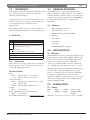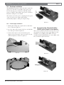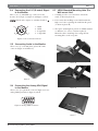
1
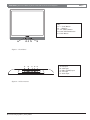
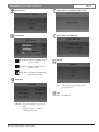
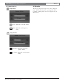
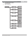
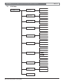
17-inch Color LCD Flat Panel Display Monitor
Instruction Manual
EN MON170CL
MON170CL | Instruction Manual | Important Safeguards
EN | 2
Important Safeguards
1. Read, Follow, and Retain Instructions - All safety
and operating instructions should be read and
followed before operating the unit. Retain instructions
for future reference.
2. Heed Warnings - Adhere to all warnings on the unit
and in the operating instructions.
3. Attachments - Attachments not recommended by the
product manufacturer should not be used, as they may
cause hazards.
4. Installation Cautions - Do not place this unit on an
unstable stand, tripod, bracket, or mount. The unit may
fall, causing serious injury to a person and serious
damage to the unit. Use only manufacturerrecommended accessories, or those sold with the
product. Mount the unit per the manufacturer's
instructions. Appliance and cart combination should
be moved with care. Quick stops, excessive force, or
uneven surfaces may cause the appliance and cart
combination to overturn.
5. Cleaning - Unplug the unit from the outlet before
cleaning. Follow any instructions provided with the
unit. Generally, using a damp cloth for cleaning is
sufficient. Do not use liquid cleaners or aerosol
cleaners.
6. Servicing - Do not attempt to service this unit
yourself. Opening or removing covers may expose you
to dangerous voltage or other hazards. Refer all
servicing to qualified service personnel.
7. Damage Requiring Service - Unplug the unit from the
main AC power source and refer servicing to qualified
service personnel under the following conditions:
• When the power supply cord or plug is damaged.
• If liquid has been spilled or an object has fallen into
the unit.
• If the unit has been exposed to water and/or
inclement weather (rain, snow, etc.).
• If the unit does not operate normally, when following
the operating instructions. Adjust only those
controls specified in the operating instructions.
Improper adjustment of other controls may result in
damage, and require extensive work by a qualified
technician to restore the unit to normal operation.
• If the unit has been dropped or the cabinet
damaged.
• If the unit exhibits a distinct change in performance,
this indicates that service is needed.
8. Replacement Parts - When replacement parts are
required, the service technician should use
replacement parts specified by the manufacturer or
that have the same characteristics as the original part.
Unauthorized substitutions may result in fire, electrical
shock or other hazards.
9. Safety Check - Upon completion of servicing or
repairs to the unit, ask the service technician to
perform safety checks to ensure proper operating
condition.
Bosch Security Systems | 6 July 2005
10. Power Sources - Operate the unit only from the type
of power source indicated on the label. If unsure of
the type of power supply to use, contact your dealer
or local power company.
• For units intended to operate from battery power,
refer to the operating instructions.
• For units intended to operate with External Power
Supplies, use only the recommended approved
power supplies.
• For units intended to operate with a limited power
source, this power source must comply with
EN60950. Substitutions may damage the unit or
cause fire or shock.
• For units intended to operate at 24VAC, normal input
voltage is 24VAC. Voltage applied to the unit's
power input should not exceed 30VAC.
User-supplied wiring, from the 24VAC supply to
unit, must be in compliance with electrical codes
(Class 2 power levels). Do not ground the 24VAC
supply at the terminals or at the unit's power supply
terminals.
11. Coax Grounding - If an outside cable system is
connected to the unit, ensure that the cable system is
grounded. U.S.A. models only - Section 810 of the
National Electrical Code, ANSI/NFPA No.70, provides
information regarding proper grounding of the mount
and supporting structure, grounding of the coax to a
discharge unit, size of grounding conductors, location
of discharge unit, connection to grounding electrodes,
and requirements for the grounding electrode.
12. Grounding - This unit may be equipped with a 3-wire
grounding plug (a plug with a third pin, for grounding).
This safety feature allows the plug to fit into a
grounding power outlet only. If unable to insert the
plug into the outlet, contact an electrician to arrange
replacement of the obsolete outlet. Do not defeat the
safety purpose of the grounding plug.
• Outdoor equipment should only be connected to
the unit's inputs after this unit has had its grounding
plug connected to a grounded outlet or its ground
terminal properly connected to a ground source.
• The unit's input connectors must be disconnected
from outdoor equipment before disconnecting the
grounding plug or grounding terminal.
• Proper safety precautions such as grounding should
be followed for any outdoor device connected to
this unit.
13. Lightning - For added protection during a lightning
storm, or when this unit is left unattended and unused
for long periods of time, unplug the unit from the wall
outlet and disconnect the cable system. This will
prevent damage to the unit due to lightning and power
line surges.
EN | 3
MON170CL | Instruction Manual | Safety Precautions
For Indoor Product
1. Water and Moisture - Do not use this unit near
water - for example, in a wet basement, in an
unprotected outdoor installation or in any area
classified as a wet location.
2. Object and Liquid Entry - Never push objects of
any kind into this unit through openings, as they
might touch dangerous voltage points or create
short circuits, resulting in a fire or electrical shock.
Never spill liquid of any kind on the unit.
3. Power Cord and Power Cord Protection - For
units intended to operate with 230VAC, 50Hz, the
input and output power cord must comply with the
latest versions of IEC Publication 227 or IEC
Publication 245.
Power supply cords should be routed so they are
not likely to be walked on or pinched. Pay
particular attention to location of cords and plugs,
convenience receptacles, and the point of exit
from the appliance.
4. Overloading - Do not overload outlets and
extension cords; this can result in a risk of fire or
electrical shock.
For Outdoor Product
Power Lines - An outdoor system should not be
located in the vicinity of overhead power lines,
electric lights or power circuits, or where it may
contact such power lines or circuits. When
installing an outdoor system, extreme care should
be taken to keep from touching power lines or
circuits, as this contact might be fatal. U.S.A.
models only - refer to the National Electrical Code
Article 820 regarding installation of CATV
systems.
For Rack-mount Product
1. Ventilation - Do not place this equipment in a
built-in installation or rack, unless proper ventilation
is provided, or the manufacturer's instructions
were followed. The equipment must not exceed its
maximum operating temperature requirements.
2. Mechanical Loading - When rack-mounting the
equipment, ensure that a hazardous condition is
not created by uneven mechanical loading.
Bosch Security Systems | 6 July 2005
Safety Precautions
CAUTION: TO REDUCE THE RISK OF
ELECTRIC SHOCK, DO NOT REMOVE COVER
(OR BACK). NO USER SERVICEABLE PARTS
INSIDE. REFER SERVICING TO QUALIFIED
SERVICE PERSONNEL.
This symbol indicates the presence of
uninsulated “dangerous voltage” within the
product’s enclosure that can cause an
electric shock.
This symbol indicates the presence of
important operating and maintenance
(servicing) instructions in the literature
accompanying the appliance.
Installation should be performed by qualified
service personnel only in accordance with the
National Electrical Code or applicable local
codes.
Power Disconnect. Units with or without
ON-OFF switches have power supplied to the
unit whenever the power cord is inserted into the
power source; however, the unit is operational
only when the ON-OFF switch is in the ON
position. The power cord is the main power
disconnect for all units.
Cover Removal
WARNING: Removal of the cover should only be
performed by qualified service personnel - not user
serviceable. The unit should always be unplugged before
removing the cover and remain unplugged while the cover
is removed.
MON170CL | Instruction Manual | FCC & ICES Information
FCC & ICES INFORMATION
(U.S.A. and Canadian Models Only)
This device complies with part 15 of the FCC Rules. Operation is
subject to the following two conditions:
(1)
This device may not cause harmful interference, and
(2)
This device must accept any interference received,
including interference that may cause undesired operation.
NOTE: This equipment has been tested and found to comply with
the limits for a Class B digital device, pursuant to Part 15 of the
FCC Rules and ICES-003 of Industry Canada. These limits are
designed to provide reasonable protection against harmful
interference when the equipment is operated in a residential
installation. This equipment generates, uses and can radiate radio
frequency energy, and if not installed and used in accordance with
the instructions, may cause harmful interference to radio
communications. However, there is no guarantee that interference
will not occur in a particular installation. If this equipment does
cause harmful interference to radio or television reception, which
can be determined by turning the equipment off and on, the user is
encouraged to try to correct the interference by one or
more of the following measures:
• Reorient or relocate the receiving antenna.
• Increase the separation between the equipment and receiver.
• Connect the equipment into an outlet on a circuit different from
that to which the receiver is connected.
• Consult the dealer, or an experienced radio/TV technician for
help.
Intentional or unintentional changes or modifications, not expressly
approved by the party responsible for compliance, shall not be
made. Any such changes or modifications could void the user’s
authority to operate the equipment.The user may find the following
booklet, prepared by the Federal Communications Commission,
helpful: How to Identify and Resolve Radio-TV Interference
Problems. This booklet is available from the U.S. Government
Printing Office, Washington, DC 20402,
Stock No. 004-000-00345-4.
Bosch Security Systems | 6 July 2005
EN | 4
MON170CL | Instruction Manual | Contents
EN | 5
Table of Contents
Important Safeguards . . . . . . . . . . . . . . . . . . . . . . . . . . . . . . . . . . . . . . . . . . . . . . . . . . . . . . . . . . . . . . . . . . . . . . .2
FCC Information . . . . . . . . . . . . . . . . . . . . . . . . . . . . . . . . . . . . . . . . . . . . . . . . . . . . . . . . . . . . . . . . . . . . . . . . . . . .4
Front Panel and I/O Connector Diagrams . . . . . . . . . . . . . . . . . . . . . . . . . . . . . . . . . . . . . . . . . . . . . . . . . . . . . . .6
1.0
UNPACKING . . . . . . . . . . . . . . . . . . . . . . . . . . . . . . . . . . . . . . . . . . . . . . . . . . . . . . . . . . . . . . . . . . . . . . . .7
1.1
Parts List . . . . . . . . . . . . . . . . . . . . . . . . . . . . . . . . . . . . . . . . . . . . . . . . . . . . . . . . . . . . . . . . . . . . . . . . . . . .7
2.0 SERVICE . . . . . . . . . . . . . . . . . . . . . . . . . . . . . . . . . . . . . . . . . . . . . . . . . . . . . . . . . . . . . . . . . . . . . . . . . . . .7
3.0 GENERAL FEATURES . . . . . . . . . . . . . . . . . . . . . . . . . . . . . . . . . . . . . . . . . . . . . . . . . . . . . . . . . . . . . . . .7
3.1
Features . . . . . . . . . . . . . . . . . . . . . . . . . . . . . . . . . . . . . . . . . . . . . . . . . . . . . . . . . . . . . . . . . . . . . . . . . . . .7
4.0 INTRODUCTION . . . . . . . . . . . . . . . . . . . . . . . . . . . . . . . . . . . . . . . . . . . . . . . . . . . . . . . . . . . . . . . . . . . .7
4.1
Monitors . . . . . . . . . . . . . . . . . . . . . . . . . . . . . . . . . . . . . . . . . . . . . . . . . . . . . . . . . . . . . . . . . . . . . . . . . . . .7
5.0 INSTALLATION . . . . . . . . . . . . . . . . . . . . . . . . . . . . . . . . . . . . . . . . . . . . . . . . . . . . . . . . . . . . . . . . . . . . . .7
5.1
Power . . . . . . . . . . . . . . . . . . . . . . . . . . . . . . . . . . . . . . . . . . . . . . . . . . . . . . . . . . . . . . . . . . . . . . . . . . . . . .7
5.2 Desktop Installation . . . . . . . . . . . . . . . . . . . . . . . . . . . . . . . . . . . . . . . . . . . . . . . . . . . . . . . . . . . . . . . . . .8
5.2.1 Power Supply Installation . . . . . . . . . . . . . . . . . . . . . . . . . . . . . . . . . . . . . . . . . . . . . . . . . . . . . . . . . . . . . .8
5.3 Connecting the Composite Video (CVBS) Input Signal to the Monitor . . . . . . . . . . . . . . . . . . . . . . . .8
5.4 Connecting the Y/C (S-video) Signal to the Monitor . . . . . . . . . . . . . . . . . . . . . . . . . . . . . . . . . . . . . . . .8
5.5 Connecting Audio to the Monitor . . . . . . . . . . . . . . . . . . . . . . . . . . . . . . . . . . . . . . . . . . . . . . . . . . . . . . . .9
5.6 Connecting the Analog VGA Signal to the Monitor . . . . . . . . . . . . . . . . . . . . . . . . . . . . . . . . . . . . . . . . .9
5.7
VESA standard mounting hole . . . . . . . . . . . . . . . . . . . . . . . . . . . . . . . . . . . . . . . . . . . . . . . . . . . . . . . . . .9
5.8 Ventilation . . . . . . . . . . . . . . . . . . . . . . . . . . . . . . . . . . . . . . . . . . . . . . . . . . . . . . . . . . . . . . . . . . . . . . . . . . .10
6.0 OPERATION . . . . . . . . . . . . . . . . . . . . . . . . . . . . . . . . . . . . . . . . . . . . . . . . . . . . . . . . . . . . . . . . . . . . . . . .10
6.1
Front Panel Controls . . . . . . . . . . . . . . . . . . . . . . . . . . . . . . . . . . . . . . . . . . . . . . . . . . . . . . . . . . . . . . . . . .10
6.2 On-screen Display (OSD) Menu . . . . . . . . . . . . . . . . . . . . . . . . . . . . . . . . . . . . . . . . . . . . . . . . . . . . . . . .10
6.2.1 CVBS/ S-VIDEO/ VGA Mode . . . . . . . . . . . . . . . . . . . . . . . . . . . . . . . . . . . . . . . . . . . . . . . . . . . . . . . . .10
6.2.2 VGA Mode Only . . . . . . . . . . . . . . . . . . . . . . . . . . . . . . . . . . . . . . . . . . . . . . . . . . . . . . . . . . . . . . . . . . . . .12
6.3 Notation . . . . . . . . . . . . . . . . . . . . . . . . . . . . . . . . . . . . . . . . . . . . . . . . . . . . . . . . . . . . . . . . . . . . . . . . . . . .12
7.0
ON-SCREEN DISPLAY MENU CONFIGURATION . . . . . . . . . . . . . . . . . . . . . . . . . . . . . . . . . . . . . . .13
7.1
CVBS Mode . . . . . . . . . . . . . . . . . . . . . . . . . . . . . . . . . . . . . . . . . . . . . . . . . . . . . . . . . . . . . . . . . . . . . . . .13
7.2
VGA Mode . . . . . . . . . . . . . . . . . . . . . . . . . . . . . . . . . . . . . . . . . . . . . . . . . . . . . . . . . . . . . . . . . . . . . . . . . .14
8.0 Appendix A - Technical Specficications . . . . . . . . . . . . . . . . . . . . . . . . . . . . . . . . . . . . . . . . . . . . . . . . . .15
Bosch Security Systems | 6 July 2005
EN | 6
MON170CL | Instruction Manual | Front Panel and I/O Connector Diagrams
Key:
A. “ i ” (Info) Button
B: -, + Buttons
C: “ M ” (Menu) Button
D: Power LED Identification
E: Power Button
A
B C D
E
Figure 1: Front Panel
A
B
C
Figure 2: I/O Connectors
Bosch Security Systems | 6 July 2005
D
E
A:
B:
C:
D:
E:
DC input
VGA input
Video (CVBS) input
Y/C input
Audio input
EN | 7
MON170CL | Instruction Manual | Unpacking
1.0
UNPACKING
This equipment should be unpacked and handled with
care. If an item appears to have been damaged in
shipment, notify the shipper.
Verify that all parts shown in the Parts List have been
included. If any items are missing, notify your Bosch
Security Systems Sales or Customer Service
Representative.
The original packing carton is the safest container in
which to transport the unit. Save it for possible future use.
1.1 Parts List
Qty
Item
1
MON170CL Color LCD Flat Panel Monitor and Stand
2
Two (2) Power Cords: 3-wire with grounded plug, 1.8m
(6ft) long; One (1) with European Continental plug type
and one (1) with U.S. plug type
3.0
GENERAL FEATURES
The MON170CL is a 17-inch TFT monitor with a
1280 x 1024 XGA resolution which has been designed
to display both PC and Video images. It complies with
the power management regulations of VESA DPMS, it
is supported by Plug & Play, and complies with
DDC1/2B.
3.1
Features
•
100 to 240 VAC Auto-detect
•
NTSC/PAL Auto-detect
•
High Resolution (1280 X 1024 XGA)
•
PC Input
•
Video Input
•
Audio Input
•
Y/C Input
•
OSD with Multiple Languages
1
Power supply
1
One (1) Analog VGA cable, 1.5 m (5 ft)
4.0
1
One (1) Audio Cable, 1.6 m (5.3 ft)
4.1
1
RCA Jack to BNC converter
1
Installation & Operation Instructions (this manual)
The MON170CL 17-inch (43 cm) Color Liquid Crystal
Display Monitor displays PAL or NTSC standard color
pictures in CCTV systems. The MON170CL monitor
includes one (1) Composite Video input RCA
connector (one RCA to BNC connector is included),
one (1) Audio input mini phone jack, and one (1) Y/C
(S-video) input using 4-pin mini-DIN. In addition, this
model includes an Analog VGA input using 15-pin
Dsub to accommodate the increasing use of Personal
Computers and digital video devices in security
applications. Monitor control functions are accessed via
the front panel push buttons and the multi-language
On-Screen Display (OSD).
2.0
SERVICE
If the unit needs servicing, contact the nearest Bosch
Security Systems Service Center for authorization to
return and shipping instructions.
Service Centers
USA
Phone:
800-366-2283 or 717-735-6638
Fax:
800-366-1329 or 717-735-6639
CCTV Spare Parts
Phone:
800-894-5215 or 408-956-3853 or 3854
Fax:
408-957-3198
E-mail:
[email protected]
Canada
Phone:
514-738-2434
Europe, Middle East & Asia Pacific Region
Phone:
32-1-440-0711
For additional information, see ww.boschsecurity.com.
Bosch Security Systems | 6 July 2005
5.0
5.1
Model
No.
INTRODUCTION
Monitors
INSTALLATION
Power
Rated
Voltage
Voltage
Range
Power
Sync
at Rated Format
Voltage
MON170CL 120/230 VAC 100 to 240 V 30 W NTSC/PAL
EN | 8
MON170CL | Instruction Manual | Installation
5.2
Desktop Installation
The MON170CL monitor is delivered with a 3-pole US
style power cord and a 3-pole Euro style power cord.
Use the US style power cord where 120 VAC, 60 Hz
power is available, and the Euro style power cord where
230 VAC, 50 Hz power is available.
The monitor end of the power cord plugs into the power
connector at the power adapter. The monitor
automatically adjust to either power input voltage.
Photo C
5.2.1 Power Supply Installation
1. Turning the locking clip a quarter turn to unlock the
base, as shown in photo A.
2. Lose the clips on the bottom of the base and fold the
base unit up, as shown in photo B.
3. Connect the bayonet connector from the power
supply to the power input connector on the rear side
of the LCD panel, as shown in photo C.
Photo A
Photo B
Bosch Security Systems | 6 July 2005
5.3
Connecting the Composite Video
(CVBS) Input Signal to the Monitor
There is one (1) RCA connector located on the rear of
the monitor for composite video input (Figure 2); also
included is one (1) RCA Jack to BNC converter
(included with the MON170CL) to connect BNC cable
line, as shown in photo D and E.
Photo D
Photo E
EN | 9
MON170CL | Instruction Manual | Installation
5.4
Connecting the Y/C (S-video) Signal
to the Monitor
5.7
VESA Standard Mounting Hole (For
Wall-mount Use)
There is one (1) mini-DIN type connector for the
S-video (Y/C) input (see Figure 2 and Figure 3 below).
1. Carefully press the cover and remove it from the
stand. (as shown in photo G)
NOTE: Both Y and C inputs are terminated with 75
2. Unscrew the three holdings screws hidden under the
high cover before separating the stand from the panel.
(as shown in photo H)
3
4
2
1
1.
2.
3.
4.
GND
GND
Y-signal IN
C-signal IN
3. The square mounting hole patterns are VESA standard
on 100 mm (3.9 centers, as shown in photo I).
Mount the unit to mounting device using the four
mounting holes on the rear panel.
Figure 3: Y/C Connection Pinout
5.5
Connecting Audio to the Monitor
There is one (1) set of mini phone jack for the audio
connector (Figure 2 and Photo F).
Photo G
Photo F
5.6
Connecting the Analog VGA Signal
to the Monitor
Photo H
There is one (1) 15-pin D-sub connector (Figure 4) for one
analog VGA input. Refer to Figure 2, item B.
Figure 4: Analog VGA Connector
Photo I
Bosch Security Systems | 6 July 2005
EN | 10
MON170CL | Instruction Manual | Operation
5.8
Ventilation
Color Temp. (For CVBS/S-VIDEO only)
To prevent overheating, ensure that the ventilation
openings on the rear of the monitor are not covered.
6.0
OPERATION
6.1
Front Panel Controls (Figure 1)
(i) Input
• Press this button to display the input
signal which is selected on the screen
• Press the button to exit OSD menu.
+/-
+’ or ‘--’ button to move the
• Press the ‘+
cursor to the targeted parameter in
the OSD main menu.
+’ or ‘--’ button to adjust the
• Press the ‘+
value of the selected parameter in the
OSD sub-menu.
(M) MENU
• Press this button to open the main
OSD menu. Use this button to
confirm a value for a parameter in
the OSD Menu.
Power LED
Identification
• Power on (Green)
• Stand by (Amber)
• Sleeping mode (Flashing Amber)
POWER
• Press this button to turn on or turn
off the monitor.
6.2
6.2.1
Tint: Adjusts the tint value (NTSC only).
(0-100)
Color: Adjusts the color value. (0-100)
Color Temp. (For VGA only)
Selecting "User" will display the following menu:
On -Screen Display (OSD) Menu
CVBS/ S-VIDEO/ VGA Mode
Luminance
R (Red): Adjusts the red color contrast.
G (Green): Adjusts the green color contrast.
B (Blue): Adjusts the blue color contrast.
Contrast: Adjusts the contrast value.
(0-100)
Brightness: Adjusts the brightness value.
(0-100)
Bosch Security Systems | 6 July 2005
EN | 11
MON170CL | Instruction Manual | Operation
Input Select
Information (For CVBS/S-VIDEO only)
OSD Setup
Information (For VGA only)
H. Position: Adjusts the OSD horizontal
position. (0-100)
Reset
V. Position: Adjusts the OSD vertical
position. (0-100)
OSD Timeout: Adjusts the OSD window
display time. (0-100)
Language
Reset: Returns the monitor setting to the
factory default.
Exit
Exits the OSD menu.
Language: Select the language to be used in
OSD.
[English / Français / Italiano
/ Deutsch / Español].
Bosch Security Systems | 6 July 2005
EN | 12
MON170CL | Instruction Manual | Operation
6.2.2 VGA Mode Only
Image Setup
Focus: Adjusts the focus value. (0-100)
Clock: Adjusts the clock frequency.
(0-177)
Image Position
H. Position: Adjusts the horizontal
position. (0-100)
V. Position: Adjusts the vertical position.
(0-100)
Bosch Security Systems | 6 July 2005
6.3 Notation
The message "Input Not supported " will be displayed
in the VGA mode if the PC is operating with either a
resolution or timing mode that is not supported by the
MON170CL.
EN | 13
MON170CL | Instruction Manual | On-Screen Display Menu Configuration
7.0
ON-SCREEN DISPLAY MENU
CONFIGURATION
7.1
CVBS/ S-VIDEO Mode
Contrast
CVBS/ S-VIDEO
Luminance
Brightness
Tint
Color Temp.
Color
VGA
Input Select
S Video
CVBS
H. Position
OSD Setup
V. Position
OSD Timeout
English
Deutsch
Language
Italiano
Information
Composite
Yes
Reset
No
Exit
Bosch Security Systems | 6 July 2005
EN | 14
MON170CL | Instruction Manual | On-Screen Display Menu Configuration
7.2
VGA Mode
Contrast
VGA
Luminance
Brightness
Focus
Image Setup
Clock
H. Position
Image Position
V. Position
9300 K
Color Temp.
6500 K
User
VGA
Input Select
S Video
CVBS
H. Position
OSD Setup
V. Position
OSD Timeout
English
Deutsch
Language
Italiano
1024 x 768
Information
H: 60 KHz V: 60 Hz
VGA Input
Yes
Reset
No
Exit
Bosch Security Systems | 6 July 2005
EN | 15
MON170CL | Instruction Manual | Technical Specification
8.0
Appendix A - Technical Specification
Electrical
Power
Rated Voltage
120/230 VAC, 50/60 Hz
On-Screen Display
Voltage Range
100 to 240
Video
Power at Rated Voltage
30 W
On/Off
Contrast, Brightness, Tint (NTSC only),
Saturation
Sync Format
PAL/NTSC
Misc
Volume, Timer, Reset, Exit
LCD Panel
TFT LCD
OSD Menu
Language, OSD H Position,
Screen Size
338.0 (H) x 270.3 (V) mm (13.3 x 10.6 in.)
Viewable Picture Area
43 cm (17 in.) measured diagonally
Indicators
Pixel Pitch
0.264 (H) x 0.264 (V) mm
LED
Power On (green)
Resolution
1280 (H) x 1024 (V) pixels;
On-Screen
"Attention No Signal"
500 TV Lines Typical
Connectors
4:3 (Composite Video); 5:4 (VGA)
Composite Video In
One (1) RCA jack, BNC adapter included
Display Colors
8 bits Interface; 16 million colors
Audio In
One (1) 1/8-in. 3-cond. mini phone jack
Response Time
16 ms
Y/C (S-video)
One (1) Mini-DIN, 4-pin (in only)
Four (4) cold Cathode Fluorescent Tubes,
VGA
One (1) 15-pin D-sub
rated life 50,000 hours, at 50% brightness
Power Input
5.5 mm DC input jack
Aspect Ratio
Backlight
OSD V Position, Timer
Power Adapter (Included) Input: 100-240 VAC, 50/60 Hz
Optical Characteristics
Luminance
300 cd/m
Contrast Ratio
450:1
Mechanical
Output: 12 VDC, 4.2 A
Viewing Angle
140° horizontal, 130° vertical
Cabinet
Composite Video (CVBS)
1.0 Vp-p (0.5-1.5 Vrms)
Dimensions
Y/C (S-video)
0.7 Vp-p (Y-signal), 0.3 Vp-p (C-signal),
LCD Panel with Base
2
Video Input
Material: ABS94V0 plastic
Finish: Charcoal
75 ohm termination
VGA Input
(14.6 x 6.7 x 15.2 in.)
LCD Panel Only
Analog RGB
0.7 Vp-p (0.5-1 Vrms)
VGA Timing Modes
Fh: 30 K - 80 KHz
372 (W) x 48 (D) x 320 (H) mm
(14.6 x 1.9 x 12.6 in.)
Weight
Fv: 60 - 75 Hz
640 x 480
372 (W) x 170 (D) x 386 (H) mm
LCD Panel with Base: 3.8 kg (8.4 lb)
LCD Panel Only: 2.9 kg (6.4 lb)
60/72/75 Hz
Environmental
800 x 600
60/72/75 Hz
Temperature
1024 x 768
60/70/75 Hz
1280 x 1024
60/75 Hz
Operating: 0°C to +40°C (+32°F to +104°F)
Storage: -20°C to +60°C (-4°F to +140°F)
Humidity
95%, noncondensing at +40°C (+104°F)
Audio Input
1.0 V line level
Product Regulatory Compliance
Audio Output
Speaker: Two (2), 1 W
Electromagnetic Compatibility (EMC)
Controls
Complies with FCC Part 15, ICES-003,
Front Panel
Push-buttons
I (Input)
Selects CVBS, S-Video, VGA Input
M (Menu)
Selects On-Screen Display (OSD)
-
Adjustment Decrease
+
Adjustment Increase
Bosch Security Systems | 6 July 2005
and CE regulations
Product Safety
Complies with CE regulations, UL, CSA,
EN, and IEC Standards
Americas
Bosch Security Systems
130 Perinton Parkway
Fairport, New York, 14450, USA
Phone: +1 (585) 223 4060
+1 800 289 0096
[email protected]
http://www.boschsecurity.us
Europe, Middle East, Africa
Bosch Security Systems B.V.
P.O. Box 80002
5600 JB Eindhoven, The Netherlands
Phone: +31 (0) 40 27 83955
Fax:
+31 (0) 40 27 86668
[email protected]
http://www.boschsecurity.com
© 2005 Bosch Security Systems GmbH
F01U009370_01 05-27 | Updated July 6, 2005 | Data subject to change without notice.
Asia-Pacific
Bosch Security Systems Pte Ltd
38C Jalan Pemimpin
Singapore 577180
Phone: +65 6319 3450
Fax:
+65 6319 3499
[email protected]
http://www.boschsecurity.com