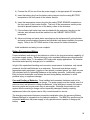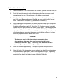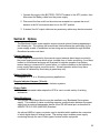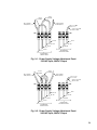
1
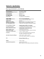
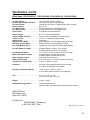
INSTRUCTION MANUAL
BLACKHAWK SERIES
BROADBAND POWER SUPPLIES
Installation and Operation Manual
Manual Part No:
017-027-B0
Issue 01 (01/23/06)
1
Documented Power Supply Models
The following power supply models, with their part numbers, are documented by this
instruction manual. For available options, refer to the OPTIONS section of this manual.
600 VA OUTPUT RATING
MODEL NUMBER
PART NUMBER
INPUTS
600-120/60-36
600-120/60-48
017-027-20
017-027-21
120VAC, 60Hz, 3-Battery
120VAC, 60 Hz, 4-Battery
600-240/60-36
600-240/60-48
017-027-22
017-027-23
240VAC, 60Hz, 3-Battery
240VAC, 60Hz, 4-Battery
600-100/50-36
600-100/50-48
017-031-23
017-031-21
100VAC, 50Hz, 3-Battery
100VAC, 50Hz, 4-Battery
600-200/50-36
600-200/50-48
017-034-20
017-034-21
200VAC, 50Hz, 3-Battery
200VAC, 50Hz, 4-Battery
900 VA OUTPUT RATING
MODEL NUMBER
PART NUMBER
INPUTS
900-120/60-36
900-120/60-48
017-028-20
017-028-21
120VAC, 60Hz, 3-Battery
120VAC, 60 Hz, 4-Battery
900-240/60-36
900-240/60-48
017-028-22
017-028-23
240VAC, 60Hz, 3-Battery
240VAC, 60Hz, 4-Battery
900-100/50-36
900-100/50-48
017-032-20
017-032-21
100VAC, 50Hz, 3-Battery
100VAC, 50Hz, 4-Battery
900-200/50-36
900-200/50-48
017-035-20
017-035-21
200VAC, 50Hz, 3-Battery
200VAC, 50Hz, 3-Battery
2
1350 VA OUTPUT RATING
MODEL NUMBER
PART NUMBER
INPUTS
1350-120/60-36
1350-120/60-48
017-030-20
017-030-21
120VAC, 60Hz, 3-Battery
120VAC, 60Hz, 4-Battery
1350-240/60-36
1350-240/60-48
017-030-22
017-030-23
240VAC, 60Hz, 3-Battery
240VAC, 60Hz, 4-Battery
1350-100/50-36
1350-100/50-48
017-033-20
017-033-21
100VAC, 50Hz, 3-Battery
100VAC, 50Hz, 4-Battery
1350-200/50-36
1350-200/50-48
017-036-20
017-036-21
200VAC, 50Hz, 3-Battery
200VAC, 50Hz, 3-Battery
3
Table of Contents
Blackhawk Series Broadband Power Supply
Section 1: Critical Safety Issues………………………………………….….5
Safety Admonishments
Emergency Shutdown Procedure
General Safety Issues
Safety Issues of Power Supply Installation and Use
Enclosure Safety Issues
Battery Safety Issues
Section 2: Introduction..................……………………….……...….....….....9
Blackhawk Series Product Overview
Blackhawk Series Product Features
Unpacking and Inspection
Missing or Damaged Items
Original Shipping Container
Other Items
Section 3: Cabinet Installation.....................………………………..….….11
Pole Mount Application
Ground Mount Application
Section 4: Front Panel Controls, Connections and Indicators………..14
Section 5: Installation and Setup............……………………………….....16
Preparation
Placement in the Enclosure
Wiring
Battery Placement and Wiring
Battery Installation Procedure
Section 6: Startup & Operation……………………………………………..20
Section 7: Power Supply Shutdown …….…………………………….….21
Section 8: Options ……………………………………………………………22
Cabinet Indicators
Battery Cable Kits
Remote Indicator Harness
Output Cable
Status Monitoring
Battery Balance Manager
4
Section 9: Maintenance and Adjustments .......................…….….……23
Preventive Maintenance
Output Voltage Reconfiguration
Input Voltage Configuration
Battery Test Time Reconfiguration
Analog Adjustments
Troubleshooting
Section 10: Specifications ………………………………………….……...29
EMI / RFI STATEMENT
This device has been designed and manufactured to comply with the limits for a Class A
digital device pursuant to Part 15 of FCC Rules. These limits are designed to provide
reasonable protection against harmful interference when this equipment is operated in a
commercial environment. This equipment generates, uses, and can radiate radio
frequency energy and, if not installed in accordance with this instruction manual, may
cause harmful interference to radio communications. Operation of this equipment in a
residential area may cause interference that the cable provider must correct at its own
expense.
Section 1: Critical Safety Issues
SAFETY ADMONISHMENTS:
Three different levels of safety admonishments are used within this instruction manual;
specifically DANGER, WARNING, and CAUTION.
The statement following the DANGER heading alerts the equipment user of a potentially
life- or health-threatening situation unless precautions are taken against it. Admonishments
of this nature usually entail the hazards of electrical shock or other such related hazards.
The statement following the WARNING heading alerts the equipment user of a condition or
procedure that could result in interruption of service. While this condition may only be a
nuisance in video-only services, it may prove to be more serious when telephony, VoIP or
data transfer services are being provided.
The statement following the CAUTION heading alerts the equipment user of a condition
that could result in damage to the subject equipment or ancillary equipment if care is not
exercised during certain maintenance or operating procedures.
SAVE THESE INSTRUCTIONS FOR FUTURE REFERENCE
5
Emergency Shutdown Procedure
DANGER
Exercise extreme caution when performing the following procedure. Carry
out the steps precisely in the order given to avoid the possibility of personal
injury or equipment damage.
Perform the following procedure if the power supply must be shut down and disconnected
on an emergency basis:
1. Switch the BATTERY CIRCUIT breaker to the OFF position.
2. Disconnect the AC power cord from the outlet in the cabinet.
3. Remove the BATTERY connector from its location at the power supply front panel.
4. Disconnect the output cable from the OUTPUT connector at the power supply front
panel.
5. Within the service entrance box or branch circuit box, operate the AC input circuit
breaker for the power supply to the OFF position.
General Safety Issues
The power supply documented in these instructions has been designed, tested and
produced to ensure safe, trouble-free operation. Personnel using or installing this power
supply should completely read and fully understand the following safety instructions. They
are provided here as informational guidelines for your continued safety in usage of the
product. These general safety issues should be observed in all phases of power supply
installation and service.
This power supply uses two sources of electrical power: commercial AC and DC derived
from a battery. Whenever performing maintenance on any of the internal components, you
must disconnect both the battery cable and AC line cord.
Always use proper lifting techniques when handling the power supply or batteries. Both the
power supply and a single 12-volt battery weigh approximately the same, about 65 pounds
(30 Kg).
Personnel installing or servicing batteries must wear eye protection (goggles or full face
shield) and protective clothing (apron and gloves) as mandated by standard operating
procedures. Additionally, only fully insulated tools specifically designed for battery
installation and service should be used for that purpose. Tools wrapped with vinyl or fabricbased electrical tape are NOT acceptable substitutes.
6
Safety Issues of Power Supply Installation and Use
The subject power supply has been designed and built to power CATV and broadband
distribution equipment only. It is not intended for any other usage and provides output
voltages suitable only for its intended application.
Power supplies documented in this instruction manual use more than one source of power.
If any reason exists to open the power supply enclosure for maintenance or adjustments,
first turn off the BATTERY CIRCUIT breaker on the front panel, disconnect the AC line cord
from its outlet and remove the BATTERY connector from its receptacle on the front panel.
Be certain that at least 5 minutes has elapsed before opening covers after disconnecting
operational power.
DANGER
This power supply operates from either a 120 volt or 240 volt AC source and produces
internal voltages in excess of 500 volts. DO NOT open any covers or panels or attempt
to perform any service to the power supply without first removing and disconnecting all
external AC and DC power sources. Only trained, qualified personnel should attempt
service and repair work on the power supply.
Install only gelled electrolyte valve regulated lead acid (VRLA) or AGM type batteries as a
standby DC source for this power supply. See the following Battery Safety Issues for
further information.
The power supply must be installed within a cabinet suitable for accommodating CATV
power supplies. If installed outdoors, the cabinet must have a 3R (rainproof) rating as a
minimum requirement. See the following Enclosure Safety Issues for further information.
Enclosure Safety Issues
The cabinet and the power supply must be installed by qualified technicians or installers
only. Whether using ground-mount or pole-mount option, appropriate mounting hardware
meeting local codes and construction practices must be used. Failure of fasteners over the
service life of the cabinet may result in hazardous conditions for the general public who
may pass near the installation.
The outer cabinet housing the power supply must be of adequate strength to support the
power supply and its associated batteries. Additionally, the cabinet must afford adequate
ventilation for the power supply such that a minimum free air space of 2-inches remains
around all sides and the top of the power supply. Air intake at the front of the inverter
module must remain unobstructed.
Temperature of the air entering the inverter module and flowing around the power supply
must not exceed 60 degrees Celsius. Air intake and exhaust openings within the outer
cabinet must not be less than 40 square inches in area. If these limits are exceeded or
7
cannot be attained, a suitable forced-air cooling system may be required within the cabinet.
Battery Safety Issues
When installing batteries for the power supply, do not mix battery types (gelled electrolyte
and AGM) in the same string or within the same cabinet. DO NOT use flooded type
batteries with liquid electrolyte with the power supply under any circumstances. Such
batteries are hazardous to use within broadband cabinets and can degrade or destroy
equipment installed in the cabinet with them. Use only gelled electrolyte or AGM batteries
of suitable size, voltage and capacity for use in a CATV system.
DANGER
Batteries can supply extremely large currents for a short period of time,
sufficient to vaporize or melt metal objects. For this reason, installers must
remove watches, rings and other jewelry before placing or connecting batteries in
the the cabinet. Insulating gloves and protective clothing should be worn during
battery installation, consistent with local practices.
Batteries contain sulphuric acid in gelled or semi-liquid form. Direct contact with any spilled
electrolyte from a damaged battery may result in skin irritation or chemical burns. For this
reason, handle batteries carefully to avoid puncturing the case and releasing any of the
electrolyte. In case of contact with the electrolyte, thoroughly wash any contaminated
areas of the skin with soap and water. In case of contact with the eyes, immediately flush
with copius amounts of water and seek medical attention. Minor surface spills can be
neutralized with an appropriate neutralizing agent such as bicarbonate of soda (baking
soda).
Always use proper lifting techniques when handling batteries. Each 12-volt battery weighs
approximately 65 pounds (30 Kg).
Personnel installing or servicing batteries must wear eye protection (goggles or full face
shield) and protective clothing (apron and gloves) if necessary, according to local practices.
Additionally, only fully insulated tools specifically designed for battery installation and
service should be used for that purpose. Tools wrapped with vinyl or fabric-based electrical
tape are NOT acceptable substitutes.
The BATTERY CIRCUIT breaker on the front panel of the power supply must be operated
to the OFF position before installing, changing and connecting batteries.
Verify correct battery polarity and voltage at the DC input connector of the power supply
before closing the BATTERY CIRCUIT breaker. Applying DC input of improper polarity or
voltage can seriously damage or entirely destroy the power supply.
Replace any battery that is found to have a swollen or cracked case. Always recycle used
batteries to reclaim lead and other materials that can pose environmental hazards if
disposed of improperly.
8
Section 2: lntroduction
Blackhawk Series Product Overview
The MultiPower Blackhawk Series power supplies provide filtered and regulated AC
output power of proper voltage and current values to operate amplifiers, nodes and
other active devices in CATV and broadband networks. These supplies are designed
to normally power the network from the commercial AC line while maintaining an
emergency battery in a state of full charge. If the commercial AC line fails for any
reason or if line voltage exceeds preset low or high limits, the low voltage inverter
within the power supply immediately begins providing power to the network load while
drawing its operating power from the battery. After commercial AC line power has
been restored, the power supply will revert to its normal operating mode supplying
power to the network load while drawing operational power from the commercial AC
line. Simultaneously, the internal battery charger within the power supply will recharge
the battery. The power supply will continue providing filtered and regulated AC to the
network load.
All Blackhawk Series power supplies operate as standby units, transferring between
power sources (AC line and inverter) in less than one cycle of power. Inverter transfer
from line mode to battery mode and from battery mode to line mode is synchronous
resulting in minimum load power anomolies. Refer to Fig. 2-1 for a typical output power
wave-form during transfer from commercial line to inverter power.
Fig. 2-1 Typical Output Transfer Waveform: Nominal 90 Volt Output, 80% Load
9
As shown in Fig. 2-1, output voltage never decreases below 90% of full output rating
during the source transfer. Output voltage recovers to full rated output within 2 cycles
following transfer. Under the test conditions in which the waveform was recorded,
output voltage was measured to be 86.30 volts RMS with 80% of full rated load applied.
Video-only services using equipment powered by standby power supplies should
exhibit little if any disturbance within the customers’ homes during a source transfer.
On the other hand, critical services such as VoIP, telephony grade communications
and data transfer may experience undesired disturbances from source transfers
between commercial AC line and inverter power. Such services may be highly
intolerant of any power anomolies, even minor disturbances that would never be
noticed on video-only services. For mission-critical services requiring an exceptionally
high degree of power integrity, system operators are advised to consider using one of
the MP Plus Series true-UPS power supplies offered by Multilink Broadband. Contact
you local Multilink sales representative for further information.
The power supplies documented in this instruction manual have been designed to
support optional HMS status monitoring. The HMS protocol supports communication
between the power supply and the monitoring device via an RS-485 serial port in an
external modem. HMS status monitoring may be installed either at the factory or in the
field as an added option.
Blackhawk Series Product Features:
o
o
o
o
o
o
o
o
o
60/75/90 VAC output operation; easily user selectable.
Serial status monitoring available, compatible with HMS-022 protocol.
High efficiency for economical line operation and longer standby run time.
Ferroresonant output: filters and regulates load power.
Status at a glance display.
High input power factor, typically 0.9 or better (line mode).
Temperature compensated charger with battery temperature sensor.
Robust inverter circuits with compact forced-air cooling.
PM (pole-mount) and GM (ground-mount) enclosure options.
Unpacking and Inspection
Before installing this equipment, inspect the power supply for shipping damage or missing
components. If the power supply or other items were damaged in shipment, file a damage
claim with the shipping company and contact your Multilink Broadband representative
immediately. Be sure to retain the original shipping carton and all packing material for the
power supply until you are certain that warranty return will not be required.
All Blackhawk Series power supplies include:
Power supply, ready for installation in cabinet
Battery temperature sensor cable
Installation and operating instructions
10
Missing or Damaged Items
If items are found to be damaged or missing, contact the shipping company and your
Multilink Broadband representative immediately. All damage claims must be filed with
the shipping company conveying your equipment. Your Multilink Broadband
representative will be able to assist with immediate equipment needs if necessary.
Original Shipping Container
When returning a unit for service, use its original shipping container and all original
packing materials. Items damaged as a result of improper packaging will not be
covered under provisions of warranty service.
Other Items
If you ordered other items such as batteries and cable kits for use with the power
supply, ensure also that those items did not sustain shipping damage. As with the
power supply itself, all damage claims must be filed with the shipping company and
your Multilink Broadband representative should be contacted immediately.
Section 3: Cabinet Installation
DANGER
Installers must exercise extreme caution during installation of a pole-mounted cabinet.
Overhead utility lines present an immediate danger to all workers since contact with a
primary utility line will result in serious injury or death.
The following procedure is intended as a general guideline only for mounting a cabinet on
a utility pole. Actual mounting methods used will be dictated by local codes and
requirements of the utility having ownership of the pole. Alternate mounting methods (such
as straps) may be employed on steel or concrete poles; however, extra care in the
selection of hardware for these mounting schemes will be required. All local codes and
standards for construction techniques must be observed when planning and executing a
pole-mount installation.
The following requirements should be noted before commencing installation activities:
Local codes may require that a service disconnect switch equipped with overcurrent
protection be installed between the power supply and the utility. The utility power
11
conductors shall be connected to the power supply through an appropriate service entrance
equipment.
Permission to mount the UPS on the utility pole shall be gained in accordance with
agreements between the cable company and the utility company.
A bucket truck and other suitable equipment, including climbing spikes and safety harness
will be required.
General Installation Procedure: Pole Mounted Cabinet
1. Using the pole mount “U” bracket as a template, drill 2 holes completely through the pole.
The diameter of the hole will depend on the hardware used, but should be slightly oversized
to allow for hole drift and bracket alignment. The “U” bracket will accommodate bolts up to
5/8-inch in diameter.
2. Observe the location of the retaining hardware to lock the “U” bracket to the cabinet back.
The holes must line up to allow the locking bolt to pass through the pole “U” bracket and
cabinet bracket to prevent the cabinet from being catastrophically dislodged from the pole if
it is struck.
3. Mount the “U” bracket to the pole using appropriate mounting hardware and through-bolts.
4. Tighten the through-bolts securely but not so snugly as to deform the “U” bracket. If the “U”
bracket is deformed, it will be impossible to engage the mating bracket on the back of the
cabinet.
5. Slide the locking bolt through the “U” bracket and the mating bracket on the rear of the
cabinet. Install the nut and tighten securely. This bolt is important since it prevents the
cabinet from being dislodged from the pole if a vehicle or other massive object impacts the
base of the pole.
6. Run necessary electrical wiring to the service entrance box on the enclosure. Observe all
national and local electrical codes. A licensed electrician must perform this step, and the
proper authorities must inspect the resulting work.
7. Connect the CATV power feed coax to the output fitting on the cabinet. In some cases it will
be necessary to terminate the coax with a pin type connector with the “stinger” (inner
conductor of the hard line) trimmed to ½- inch beyond the threaded portion of the connector
body. A right angle connector may be required, depending on specific installation
conditions at the site.
8. Recheck all mounting hardware for tightness and integrity. Recheck all wiring.
9. Install the power supply and batteries in the cabinet as outlined in this manual.
12
General Installation Procedure: Ground Mounted Cabinet
The following procedure is intended as a general guideline only for ground-mounting a
cabinet on a pad or pedestal. Actual mounting methods used will be dictated by local
codes and requirements. All local codes and standards for construction techniques must
be observed when planning and executing a cabinet installation.
The following requirements should be noted before commencing installation activities:
Obtain any and all necessary permits and easements before pouring any concrete or
installing the cabinet. Permission to mount the UPS shall be obtained in accordance with
agreements between the cable company, the utility company, and any government entity or
body having jurisdiction.
INSTALLATION NOTE: Tighten all mounting hardware securely before installing the UPS
and batteries into the cabinet. Failure to do so may result in the cabinet flipping over
and causing severe injury to the installer.
For maximum strength and security, use a poured-concrete pad. The mounting bolts should
be 7/16-inch in diameter and cast in the concrete whenever possible. Make a suitable
template of the pedestal skirt for mounting bolt placement.
Local codes may require that a service disconnect switch equipped with overcurrent
protection be installed between the power supply and the utility. The utility power
conductors shall be connected to the power supply through an appropriate service entrance
equipment.
1. Be certain the intended mounting surface, either poured concrete or pre-cast, is level and
square and that all necessary power and coaxial connections are stubbed up correctly.
2. Install the cabinet over the mounting bolts and secure to the pad with the appropriate
hardware. Tighten all hardware securely.
3. Connect electrical wiring in the service entrance box as necessary. Observe all national and
local electrical codes. A licensed electrician must perform this step, and the proper
authorities must inspect the resulting work.
4. Connect the CATV power feed coax to the output fitting on the cabinet. This connector may
be internal to the cabinet depending on the installation. In some cases it will be necessary
to terminate the coax with a pin type connector with the “stinger” (inner conductor of the
hard line) trimmed to ½- inch beyond the threaded portion of the connector body. A right
angle connector may be required, depending on specific installation conditions at the site.
13
5. INSTALLATION NOTE: Do not install batteries until verifying that the cabinet
mounting hardware is secure. Failure to do so may result in the cabinet flipping
over, causing severe injury to the installer.
6. Install the power supply and batteries in the cabinet as outlined in this manual.
Section 4: Front Panel Controls, Connections and Indicators
The front panel of the power supply contains various connectors, indicators and all operator
controls. These items are described as follows.
Controls
Circuit Breakers: Input and output circuit breakers are described as follows:
a) Output Circuit Breaker: This 20-amp circuit breaker, located at the left side of the
front panel, protects the power supply in case a fault condition occurs on the output
circuit. This circuit breaker is a push-to-reset device.
b) Battery Circuit Breaker: 80 amp circuit breaker protects battery circuit and input
wiring. This circuit breaker is also used as a DC switch to apply and remove battery
power to the power supply.
Switches: One pushbutton switch controls functions within the power supply:
TEST Switch: This switch, located below the indicator LEDs on the front panel of the
inverter module, initiates and cancels local battery test.
Connections:
Output Connectors:
The Blackhawk Series power supplies contain one power output connector, located in
the lower left corner of the front panel. The mating Anderson mini-power pole
connector provides the means for connecting output power to the appropriate network
power connector in the cabinet. The black connector is hot; the white connector is
ground return for the output.
BATTERY: Anderson-type connector: used for connecting the external battery to the
power supply.
BATTERY TEMP SENSOR: Mini Mate-N-Lok: connects the external temperature
probe for temperature compensated battery charging.
14
CABINET INDICATORS: Mini Mate-N-Lok: connects the enclosure alarm and status
lamps to the power supply for external status indication. The power supply will activate
an external green lamp to indicate normal operation or will activate a red alarm lamp to
indicate battery operation or a failure condition in need of correction.
Indicators:
A group of light emitting diodes (LEDs) on the front of the inverter module provides visual
indication of power supply operational status. These LEDs are described as follows:
Power Supply Status Indicators: The LEDs on the inverter module front panel form the
Status At A Glance display that indicates operational status of the power supply circuits.
Under normal operating conditions with line power applied and the battery fully charged, all
LEDs with the exception of the TEST indicator should illuminate green. Any alarm or
abnormal operating condition will result in one or more LEDs illuminating either amber or
red.
Any indicator of a color other than green will be easily noticed so operating or service
technicians will be able to discern, at a glance, the operational status of the power supply.
Indicators and their operational states are described as follows:
LINE: AC input LED indicates one of three status conditions:
o Green: line power available and within acceptable limits
o Amber: qualifying line following restoration
o Red: line power low in voltage or completely failed
BATTERY: Battery LED indicates one of three states:
o Green: Battery fully charged, voltage normal
o Amber: Battery charger is operating in the high rate mode
o Red: Alarm; battery is discharging or low battery cutoff point attained
SENSOR: This LED indicates status of the temperature probe:
o Green: Probe connected and operating normally
o Not illuminated: Alarm; probe has become disconnected or has failed
TEST: This indicator operates in conjunction with the remote/local battery test function.
Testing may be initiated locally by actuating the TEST switch or remotely by issuing
appropriate commands via the status monitor port. This LED indicates the
following operational states:
o Green: Testing locally by actuating the TEST switch
o Amber: Flashes when serial data is being sent to the transponder
o Red: Alarm; check battery for state-of-charge or failure condition
15
Section 5: Installation and Setup
Installing and wiring any model within the Blackhawk Series power supplies into an
enclosure may be accomplished as simply as connecting input and output wiring to the
appropriate connectors of the power supply. If wired for 120 volt AC input, the AC power
cord of the power supply mates with a standard 5-20R 120 volt, 20 amp outlet. The
230/240 volt version of the power supply requires a standard 6-15R AC outlet. All other
connectors on the front panels of the modules mate with industry-standard connectors
widely available and used within the CATV industry. Moreover, connectors used in this
power supply mate with accessory harnesses and assemblies designed and manufactured
by Multilink Broadband. Refer to the OPTIONS section of these instructions for further
information.
This power supply is designed for use in both existing and new enclosures of either pole or
ground-mount configuration. Observe the following procedures during installation of any
Blackhawk Series power supply.
Preparation:
The Blackhawk Series power supplies have been factory assembled, tested and prepared
as a complete product ready for installation within an enclosure. The installer must verify
that the correct type of AC power receptacle is installed in the enclosure for the input
service and power supply selected for use at any given site. Additionally, the correct
battery must be installed in the enclosure since the power supplies are fabricated and
adjusted for 36 or 48 volt DC input, exclusively. Power supply ratings may be verified from
the nameplate on the left side panel near the power cord.
1) Check to ensure that the correct system output voltage has been selected. The
output voltage select terminal board is located behind the left-side front panel,
allowing the user to choose output voltage of 60, 75 or 90 volts. If the output voltage
must be changed from its factory setting, refer to the SERVICE section of these
instructions for VOLTAGE RECONFIGURATION.
2) Additionally, verify that the correct battery string has been installed in the enclosure
for 36 or 48 volt battery input. Check the nameplate of the power supply or the
interior of the inverter module to determine that the DC input voltage requirements
match the configuration of the system.
Placement in the Enclosure:
This power supply has been designed primarily for use within a cabinet or enclosure
offering protection from outdoor weather, entry of excessive dust, dirt or moisture and from
unauthorized contact by untrained personnel. If used in a controlled environment, the
power supply may be located within an indoor equipment cabinet or may be mounted on a
rack shelf.
16
The power supply should be mounted on a ventilated shelf that allows free air circulation,
especially through the front and rear panels on the right side of the power supply.
Clearance of at least 2-inches for unobstructed air flow must be maintained around all
surfaces of this power supply. Temperature of the air entering the power supply should not
exceed 50 degrees C (122 degrees F).
Wiring:
Connect input, output, control and monitor wiring to the power supply according to the
following procedure. Refer to Fig. 5-1 for control and connector positions.
STATUS
INDICATORS
OUTPUT
CIRCUIT
BREAKER
CABINET
INDICATORS
CONNECTOR
BATTERY
CIRCUIT
BREAKER
OUTPUT
CONNECTOR
BATTERY
CONNECTOR
TEMP
SENSOR
CONNECTOR
Fig. 5-1 Power Supply Front Panel
1) Operate the AC line circuit breaker in the service entrance box to the OFF position.
If the power supply is located at a head end or other customer premise site, ensure
that the branch circuit breaker chosen to protect the AC receptacle for the power
supply is operated to the OFF position.
2) Operate the BATTERY CIRCUIT BREAKER on the front panel of the inverter
module to the OFF (0) position.
3) Apply the system load to the OUTPUT connector on the front panel of the power
supply. Do not attempt to load the power supply to a level greater than its total rated
output of 600, 900 or 1350 VA, depending on the model being used. Long-term
overloads can permanently damage your power supply.
17
4) Connect the AC line cord from the power supply to the appropriate AC receptacle.
5) Insert the battery plug from the battery wiring harness into the mating BATTERY
receptacle on the front panel of the inverter module.
6) Insert the temperature sensor plug into the mating TEMP SENSOR receptacle on
the front panel of the inverter module. The body of the temperature sensor probe
should be placed between two of the battery cases in the enclosure.
7) If the indicator light option has been provided with the enclosure, the plug on the
indicator wire harness should be inserted into the CABINET INDICATORS
receptacle.
8) Alarm monitoring and serial status reporting may be implemented if optional alarm
and serial communications firmware and hardware have been installed in the power
supply. Refer to the OPTIONS section of this manual for further information.
Initial installation and wiring is now complete.
Battery Placement and Wiring:
Proper installation and wiring of the batteries is critical to the long-term backup capability of
any power supply system. Gelled electrolyte, valve regulated batteries are recommended
for use in outdoor cable TV / broadband UPS and power supply applications. All batteries
should be tested and fully charged prior to installation.
In light of the specialized handling and connection requirements for batteries, only trained
personnel should install batteries in an enclosure. Personnel must always employ
appropriate safety equipment (goggles or face shields, insulated gloves, etc.) and only use
fully insulated tools for tightening hardware on the battery terminals. Additionally, proper
lifting tools and techniques must always be used during battery installation to avoid
personal injury or equipment damage.
Care and Feeding of Batteries: Once installed and connected, batteries must not be
allowed to sit idle without receiving a charge. The power supply must be started, even if at
minimum load, and allowed to charge the batteries. Initial charging to ensure full reserve
time may require as long as seven days to accomplish. Batteries connected to an idle
system without receiving a charge can be irreparably damaged, thereby requiring
replacement before the system can be fully commissioned into service.
The charging requirement becomes a special consideration when the accessory Battery
Balance Manager is integrated into the cabinet installation. The BBM Plus product may be
connected only when the power supply is fully operational and capable of charging the
battery.
18
Battery Installation Procedure:
1.
Place the batteries on the lower shelf of the enclosure, positive terminal facing out.
2.
Route the terminal connector ends of the battery cable from the power supply
compartment at the top of the enclosure to the battery compartment.
3.
Wire the batteries in series, connecting negative post of one battery to positive
post of the next. Battery cables and terminals are color coded to aid in correct
wiring. Black terminal is negative (-); red terminal is positive(+).
4.
After completing all connections to the battery terminals, use a digital multimeter
(DMM) to verify proper voltage and polarity at the battery cable connector that
terminates to the power supply DC input port. For 3-battery systems, indicated
voltage should be approximately 36 volts or slightly higher. In a 4-battery system,
indicated voltage should be approximately 48 volts or slightly higher. When the
red and black meter probes are connected to the corresponding colored terminals
of the battery harness connector, the meter should indicate positive (+) voltage,
assuming proper connections at the meter itself.
WARNING
If voltage and polarity indications do not correspond to those
described above, determine the cause before mating the battery
connector to the power supply. Incorrectly wired batteries can cause
personal injury or permanent damage to equipment.
5.
Space the batteries approximately 1 inch apart to provide adequate airflow.
6.
Attach the body of the temperature sensor probe to the side of the center battery
using self-adhesive tape rated for use in wide temperature ranges. Depending
upon battery construction, it may be necessary to hang the sensor in close
proximity to the side of the battery instead of attaching it directly.
19
Section 6:
Startup and Operation
The power supply is ready to be placed into operation after it has been installed in its
enclosure and all input and output connections have been made,. Ensure that AC input
power is available to the power supply receptacle then perform the following steps in
sequence.
CAUTION
The following steps in the startup procedure MUST be performed exactly
as presented; otherwise, permanent damage to the power supply may
result. Observe the status of the LED indicators as a guide in performing
the startup procedure.
1. Ensure that the BATTERY CIRCUIT BREAKER has been operated to the OFF (0)
position. All connections and initial wiring must be in place as previously outlined
and described.
2. Operate the utility AC circuit breaker in the service entrance box to the ON position.
The power supply should start and immediately begin delivering power to the load.
3. The LINE and SENSOR indicators should be illuminated green before proceeding.
The BATTERY indicator will illuminate red before the battery circuit breaker is
closed. The BATTERY CIRCUIT BREAKER on the front panel of the power supply
may be placed to the ON (1) position only after verifying that the LINE and SENSOR
indicators are illuminated green.
4. The BATTERY indicator should change from red to green after the BATTERY
CIRCUIT BREAKER is turned ON. Following a short time delay and with AC line
voltage within acceptable limits, the BATTERY indicator should change from green
to amber. This occurs when the internal battery charger begins delivering a high
rate charge to the external batteries. High rate charge will end automatically and is
signalled when the BATTERY indicator changes color from amber to green.
5. The power supply is now operating in its normal mode. All indicators on the front
panel of the power supply should be illuminated green, perhaps with the exception of
the CHARGER indicator which may be amber. Additionally, the TEST indicator
should either be extinguished or may flash amber occasionally as the status monitor
circuits communicate with the external transponder, if connected.
20
Front Panel Status Indicators:
Verify the status of the power supply from the LED display during normal operation.
All indicator LEDs are located on the front panel of the inverter module.
LINE (AC input /Mains)
o GREEN (nominal AC line voltage/normal operation)
o AMBER (qualifying AC line voltage)
o RED (AC input low or absent)
BATTERY
o GREEN (nominal battery voltage/normal operation)
o AMBER (high rate charge)
o RED (alarm: low voltage cutoff & sleep mode or batteries disconnected)
o RED, Blinking (alarm: batteries incapable of supporting standby operation)
SENSOR (Battery Temperature Sensor)
o GREEN (normal operation)
o Not Illuminated (disconnected or sensor fault)
TEST
o
o
o
o
GREEN (test in progress initiated locally)
AMBER (test initiated remotely)
AMBER FLASH (data communication)
RED (last test failed)
Press the TEST pushbutton switch, accessible through the front panel of the power
supply to initiate the test function locally. The power supply automatically tests the
batteries and internal circuitry for a factory-adjusted time of 5 minutes. Press the TEST
switch again to cancel the test at any time.
Backfeed Lockout Indication:
The power supply is equipped with a safety (anti-backfeed) circuit that prevents
inverter output from backfeeding the utility lines in case critical components within the
power supply fail. If the anti-backfeed circuit is activated, inverter operation is
automatically suspended and all front panel indicators, except the SENSOR indicator,
flash red. Removing both AC and DC inputs will reset the power supply and cancel
the backfeed lockout condition; however, corrective maintenance may be required to
repair the basic cause of the lockout condition.
Section 7: Power Supply Shutdown
If power supply shutdown becomes necessary at any time, observe the following
procedure:
21
1. Operate the toggle of the BATTERY CIRCUIT breaker to the OFF position, then
disconnect the battery cable from the power supply.
2. Disconnect the line cord from the enclosure receptacle or operate the circuit
breaker in the AC service entrance box to the OFF position.
3. If desired, the AC output cable and any accessory cables may be disconnected.
Section 8: Options
The Blackhawk Series power supplies support several optional features appearing in
the following list. The options and accessories listed enhance the usefulness of your
power supply as aids to installation and servicing and are available through Multilink
Broadband as extra-cost items.
Cabinet Indicators:
Power supplies documented in this manual support external alarm lamps mounted in
the power supply enclosure which act as a simple form of status monitoring. A red lamp
located on the external enclosure will illuminate to indicate operation from battery
reserve during a commercial AC power failure, or a failure condition in the batteries or
power supply that requires corrective action. Normal operation without any alarm
conditions is indicated by illuminating a green lamp only.
Battery Cable Kits:
Designed for 3, 4, 6, or 8-battery powering applications.
Remote Indicator Harness (30 inch):
Designed for use with custom remote indicator systems.
Output Cable:
28-inch unterminated cable adapts the UPS for use in a wide variety of existing
enclosures.
Status Monitoring:
The optional HMS Status Monitor may be installed in any Blackhawk Series power
supply. This method of status monitoring supports communication between the power
supply and an external transponder device via an RS-485 serial port as described in
ANSI/SCTE 25-3 2002 (HMS-022) Standard.
An optional HMS-to-Legacy converter may be installed which enables the conversion
of serial digital data into analog format. The analog output enables power supply
monitoring through the use of older types of status monitor equipment.
22
Battery Balance Manager:
This accessory, available as a separate assembly, is designed to maintain identical
terminal voltage of each 6-cell battery in the string within 130 millivolts (0.130 volt) as
measured across the entire battery string. Balancing battery voltages will help
maintain battery life to maximum attainable time and helps insure longest available
reserve time. The BBM Plus Battery Balance Manager is available for either 36-volt
applications (part no. 018-008-20) or 48-volt applications (part no. 018-009-20).
Section 9: Maintenance and Adjustments
Preventive Maintenance:
For optimum performance from your power supply, the following maintenance items
should be performed at least every six (6) months, especially in areas where the power
supply is subjected to extreme heat or cold.
o Visually inspect the enclosure for signs of damage
o Inspect the external status lamps for proper operation
o Check the status LEDs on the front of the power supply for any alarm
indications
o Check all electrical connections
o Check the batteries for signs of swelling, split cases or other damage
o Check and record individual battery voltages
o Check and clean battery terminals; bolts or wingnuts must be tight
o Measure and record AC output voltage
o Measure and record AC output current
o Measure and record DC battery voltage
o Press the TEST button on the front panel to test the batteries. Press TEST
again to cancel
o Record all maintenance performed or parts replaced
o Verify the power supply is in its normal mode of operation as indicated by the
LED display. All front panel LEDs, other than the TEST indicator, should be
illuminated green
o Close and lock the enclosure
Output Voltage Reconfiguration:
The output voltage configuration block is located on the voltage adjustment panel,
accessible after removal of the left-front cover plate. Typical connections for the
voltage adjustment panel are shown in Fig. 9-1. Voltage configuration should normally
be accomplished during initial installation of the power supply; however, if
reconfiguration becomes necessary after the power supply is placed in operation, do
so according to the following procedure.
23
WHITE
JUMPER
BLACK
JUMPER
INPUT POWER
WIRE (BLACK)
INPUT POWER
WIRE (WHITE)
OUTPUT VOLTAGE
SELECT WIRE
1
2
3
60V
4
75V
90V
TB1
TB2
BLUE
WH / BK
YELLOW
BK / WH
WHITE
ORANGE
BLACK
TRANSFORMER
SECONDARY WIRES
TRANSFORMER
PRIMARY WIRES
Fig. 9-1. Power Supply Voltage Adjustment Panel:
120VAC Input; 90VAC Output
WHITE
JUMPER
BLACK
JUMPER
INPUT POWER
WIRE (BLACK)
INPUT POWER
WIRE (WHITE)
OUTPUT VOLTAGE
SELECT WIRE
1
2
3
60V
4
75V
90V
TB1
TB2
BLUE
WH / BK
BK / WH
WHITE
YELLOW
ORANGE
BLACK
TRANSFORMER
SECONDARY WIRES
TRANSFORMER
PRIMARY WIRES
Fig. 9-2. Power Supply Voltage Adjustment Panel:
240VAC Input; 90VAC Output
24
DANGER
Performing the following procedure exposes the servicing technician to
hazardous voltages and will disrupt power to the system loads. The
servicing technician MUST verify that AC and DC input sources to the
power supply have been removed. If system power must be maintained
during output voltage reconfiguration, connect the output from a service
supply to the power insertion point of the cable before proceeding.
1.
Perform Steps 1) and 2) of the shutdown procedure appearing in Section 7) of this
manual.
2.
If necessary, ensure that power to the cable system is being provided by a service
supply. Verify that the AC input cord of the power supply has been disconnected
from its receptacle.
3.
Disconnect the output cable from the power supply, then remove the left-side front
panel. Retain all mounting hardware.
4.
Place the output voltage select wire shown in Fig. 9-1 and 9-2 into the appropriate
voltage connection terminal of TB2. Select the 60, 75 or 90-volt position as
required per system needs. Tighten the terminal board screw to secure the
voltage select jumper wire in place.
5.
Replace the left-side front panel and fasten into place using the hardware retained
from Step 3).
6.
Reconnect cables to the power supply and inverter module as required, then
restart the power supply according to the procedure contained in Section 6) of this
manual. After the power supply has been restarted, remove the service supply to
complete this procedure.
Input Voltage Configuration:
Your power supply has been manufactured, equipped and tested for the input voltage
specified on the original order, either 120 or 240 volts AC. Since certain hardware
changes and recalibration would be required, reconfiguring the power supply for a
different input voltage is not recommended as a field modification. Input voltage
reconfigurations, where and when required, should be installed only at qualified
service centers or repair facilities.
In emergency situations, where input voltage reconfiguration must be carried out for
temporary operations, perform the following procedure:
25
DANGER
Performing the following procedure exposes the servicing technician to
hazardous voltages and will disrupt power to the system loads. The
servicing technician MUST verify that AC and DC input sources to the
power supply have been removed. If system power must be maintained
during input voltage reconfiguration, connect the output from a service
supply to the power insertion point of the cable before proceeding.
1. Perform Steps 1) and 2) of the shutdown procedure appearing in Section 7) of this
manual.
2. If necessary, ensure that power to the cable system is being provided by a service
supply. Verify that the AC input cord of the power supply has been disconnected
from its receptacle.
3. Disconnect the output cable from the power supply, then remove the left-side front
panel. Retain all mounting hardware.
4. Place the input voltage select wires shown in Fig. 9-1 and 9-2 into the appropriate
voltage connection terminal of TB1. Select the 120 or 240-volt position as required
per system needs. Tighten the terminal board screws to secure the voltage select
jumper wire in place.
5. On the power supply output board, locate J10 adjacent to transformer T1. These
terminals are configured by two pin jumpers: one position for 120-volt input; the
other for 240-volt input. Refer to Fig. 9-3 for a diagram of the required pin jumper
positions. Reconfigure the positions as required, for either 120- or 240-volt
operation.
6. Locate J5 on the power supply output board. This connector is used for inserting a
metal-oxide varistor (MOV) into the power line input circuit for protection against high
voltage surges. If configuring the power supply for nominal 240 VAC input, connect
a 275 volt MOV (part no. 160-006-10) to J5. If configuring the power supply for
nominal 120 volt input, connect a 130 volt MOV (part no. 160-002-10) to J5.
7. When reconfiguration connections have been completed, replace the left-side front
panel and fasten into place using the hardware retained from Step 3).
8. Reconnect cables to the power supply and inverter module as required, then restart
the power supply according to the procedure contained in Section 6) of this manual.
After the power supply has been restarted, remove the service supply to complete
this procedure.
26
INDICATES JUMPER
CONNECTED OVER
DESIGNATED PINS
700-064-20
700-064-21
OUTPUT INTERFACE
PCB ASSEMBLY
2 4 6 8
1 3 5 7
T1
J1
J10
240V SETTING
2 4 6 8
1 3 5 7
RELAY K2
INSTALLED HERE
120V SETTING
Fig. 9-3. Power Supply Voltage Configuration Jumpers:
J10 on 700-064-20 Output Board
Battery and Test Time Configuration:
The test time and battery configuration jumpers are located on the trace side of the
control circuit board located in the inverter module. The jumpers are factory-adjusted
for a test time of approximately 5 minutes. Re-adjustment of test time in the field is
neither recommended nor necessary since shorter or longer times may not sufficiently
test battery reserve or may use an excessive amount of reserve if a commercial AC line
failure occurs during the test cycle.
Battery configuration jumpers have been factory adjusted for 3, 4, 6 or 8-battery
installations per customer order. Resetting the pin jumpers for battery configuration is
neither recommended nor should it ever be necessary to do so.
Analog Adjustments:
Several miniature potentiometers are located on the printed wiring board of the inverter
module. These potentiometers have been factory adjusted for proper charger output
voltage and for correct detection and measurement thresholds. Field adjustment of any
potentiometer in the inverter module should not be attempted; otherwise, degraded power
system performance or damage to the inverter module or batteries may result. If any
potentiometer adjustments are suspected as a cause of operational trouble or erroneous
27
performance reporting, the entire inverter module should be changed in the field. The
module with suspected problems should be returned to a service center or the factory for
diagnosis and repair.
Troubleshooting:
The troubleshooting guide has been designed to help you quickly locate and resolve
common powering problems. If you still cannot solve the problem, replace the inverter
module or entire power supply with a known good unit.
CONDITION
No output to load
Batteries connected
AC line power present
CHECK
Output connector plugged in
Battery voltage OK
Output circuit breaker
CONDITION
Incorrect output voltage
Batteries connected
AC line power present
CHECK
OUTPUT select indicator
CONDITION
Batteries will not charge
Batteries connected
AC line power present
CHECK
Battery breaker tripped
Battery terminals and connectors
Battery failure
CONDITION
Batteries not properly charged
Batteries connected
AC line power present
CHECK
Verify connection of battery cable
Verify charger mode at front panel
Measure charge voltage (Rapid, Float)
CONDITION
Front panel test indicators
amber
Batteries connected
CHECK
Remote testing
Batteries not yet fully charged
28
Section 10: Specifications
Black Hawk 600-120/60-36 or 600-120/60-48
AC Input Voltage ………………………
Nominal Input Voltage Tolerance ..…
AC Input Current ………………………
Input Frequency ………………………..
Line Reject Value ………………………
Line Accept Value ……………………..
Power Factor ……………………………
120 volts AC, nominal
±10% (108-132 volts)
6 amps, nominal
60, ± 3 Hz
95 VAC, nominal
105 VAC, nominal
0.9 typical (line mode operation)
Output Voltage ………………………… 60 / 75 / 89 VAC selectable taps
Output Voltage Tolerance …………… +5% and –2% load regulation over input range
Output Current ………………………… 10 / 8 / 6.7 amps (into resistive load)
Output Power …………………………… 600 watts
Efficiency (Line Mode) ………………… Better than 90% over line voltage range, at full load
Efficiency (Inverter Mode) ……………. Better than 85% at nominal battery, full load
Run Time (Battery Input) ……………… Greater than 2 hours @ full load with 90A-H battery
DC Input (Battery) Voltage …………… 3-battery system (18-cells): 36V nominal
4-battery system (24-cells): 48V nominal
Low Battery Shutdown ……………….. 1.75 V/cell (31.5V for 18-cells or 42.0V for 24-cells)
Battery Acceptance Voltage …………. 3-battery system: not less than 28 volts
4-battery system: not less than 38 volts
Battery Charge Current ……………….. 5 amps @ nominal AC input
Battery Float Voltage ………………….. 2.27 V/ cell (41.0V for 18-cells or 54.6V for 24-cells)
Temperature Compensation …………. -0.05V/°F (-0.09V/°C) slope
Protection ……………………………….. DC Input: 80A magnetic/hydraulic circuit breaker
AC Output: 20A thermal circuit breaker
Operating Temperature Range ……… -40°C to +60°C (-40°F to +140°F)
At 5% to 95% relative humidity, non-condensing
Size ………………………………………. 8.6” H x 15” W x 12.5” D
(219 mm x 381 mm x 318 mm)
Weight …………………………………… xx Lbs. (xx Kg)
Status Monitoring Options ………….. StatTrak (HMS protocol)
HMS-to-Legacy converter allowing analog status monitoring
29
Specifications (cont’d)
Black Hawk 900-120/60-36; 900-120/60-48; 900-240/60-36; 900-240/60-48
AC Input Voltage ………………………
Nominal Input Voltage Tolerance ..…
AC Input Current ………………………
Input Frequency ………………………..
Line Reject Value ………………………
Line Accept Value ……………………..
Power Factor ……………………………
120 volts or 240 volts AC, nominal
±10% (108-132 volts or 216-264 volts)
10 amps @ 120V input or 5 amps @ 240V input, nominal
60, ± 3 Hz
95V @ 120V input or 192V @ 240V input
105V @ 120V input or 210V @ 240V input
0.9 typical (line mode operation)
Output Voltage ………………………… 60 / 75 / 89 VAC selectable taps
Output Voltage Tolerance …………… +5% and –2% load regulation over input range
Output Current ………………………… 15 / 12 / 10 amps (into resistive load)
Output Power …………………………… 900 watts
Efficiency (Line Mode) ………………… Better than 90% over line voltage range, at full load
Efficiency (Inverter Mode) ……………. Better than 85% at nominal battery, full load
Run Time (Battery Input) ……………… Greater than 2 hours @ full load with 90A-H battery
DC Input (Battery) Voltage …………… 3-battery system (18-cells): 36 V nominal
4-battery system (24-cells): 48 V nominal
Low Battery Shutdown ……………….. 1.75 V/cell (31.5V for 18-cells or 42.0V for 24-cells)
Battery Acceptance Voltage …………. 3-battery system: not less than 28 volts
4-battery system: not less than 38 volts
Battery Charge Current ……………….. 5 amps @ nominal AC input
Battery Float Voltage ………………….. 2.27 V/ cell (41.0V for 18-cells or 54.6V for 24-cells)
Temperature Compensation …………. -0.05V/°F (-0.09V/°C) slope
Protection ……………………………….. DC Input: 80A magnetic/hydraulic circuit breaker
AC Output: 20A thermal circuit breaker
Operating Temperature Range ……… -40°C to +60°C (-40°F to +140°F)
At 5% to 95% relative humidity, non-condensing
Size ………………………………………. 8.6” H x 15” W x 12.5” D
(219 mm x 381 mm x 318 mm)
Weight …………………………………… xx Lbs. (xx Kg)
Status Monitoring Options ………….. StatTrak (HMS protocol)
HMS-to-Legacy converter allowing analog status monitoring
30
Specifications (cont’d)
Black Hawk 1350-120/60-36; 1350-120/60-48; 1350-240/60-36; 1350-240/60-48
AC Input Voltage ………………………
Nominal Input Voltage Tolerance ..…
AC Input Current ………………………
Input Frequency ………………………..
Line Reject Value ………………………
Line Accept Value ……………………..
Power Factor ……………………………
120 volts or 240 volts AC, nominal
±10% (108-132 volts or 216-264 volts)
14 amps @ 120V input or 7 amps @ 240V input, nominal
60, ± 3 Hz
95V @ 120V input or 192V @ 240V input
105V @ 120V input or 210V @ 240V input
0.9 typical (line mode operation)
Output Voltage ………………………… 60 / 75 / 89 VAC selectable taps
Output Voltage Tolerance …………… +5% and –2% load regulation over input range
Output Current ………………………… 22.5 / 18 / 15 amps (into resistive load)
Output Power …………………………… 1350 watts
Efficiency (Line Mode) ………………… Better than 90% over line voltage range, at full load
Efficiency (Inverter Mode) ……………. Better than 85% at nominal battery, full load
Run Time (Battery Input) ……………… Greater than 2 hours @ full load with 90A-H battery
DC Input (Battery) Voltage …………… 3-battery system (18-cells): 36 V nominal
4-battery system (24-cells): 48 V nominal
Low Battery Shutdown ……………….. 1.75 V/cell (31.5V for 18-cells or 42.0V for 24-cells)
Battery Acceptance Voltage …………. 3-battery system: not less than 28 volts
4-battery system: not less than 38 volts
Battery Charge Current ……………….. 5 amps @ nominal AC input
Battery Float Voltage ………………….. 2.27 V/ cell (41.0V for 18-cells or 54.6V for 24-cells)
Temperature Compensation …………. -0.05V/°F (-0.09V/°C) slope
Protection ……………………………….. DC Input: 80A magnetic/hydraulic circuit breaker
AC Output: 20A thermal circuit breaker
Operating Temperature Range ……… -40°C to +60°C (-40°F to +140°F)
at 5% to 95% relative humidity, non-condensing
Size ………………………………………. 8.6” H x 15” W x 12.5” D
(219 mm x 381 mm x 318 mm)
Weight …………………………………… xx Lbs. (xx Kg)
Status Monitoring Options ………….. StatTrak (HMS protocol)
HMS-to-Legacy converter allowing analog status monitoring
MULTILINK Inc.
580 Ternes Ave.
Elyria, OH 44035
Contact us at:
440-366-6966 (Telephone)
or 440-366-1036 (Fax)
Manual part no: 017-022-A1
31