1
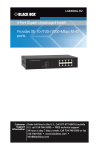
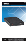
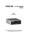
LB304A LBPS301A LBPS304A Hardened Ethernet Extender User’s Manual Provides one channel for Ethernet over existing BLACK voice-grade twisted-pair copper wire. BOX ® Customer Support Information Order toll-free in the U.S.: Call 877-877-BBOX (outside U.S. call 724-746-5500) FREE technical support 24 hours a day, 7 days a week: Call 724-746-5500 or fax 724-746-0746 Mailing address: Black Box Corporation, 1000 Park Drive, Lawrence, PA 15055-1018 Web site: www.blackbox.com • E-mail: [email protected] Trademarks Used in this Manual Trademarks Used in this Manual Black Box® and the Double Diamond logo are registered trademarks of BB Technologies, Inc. UL is a registered trademark of Underwriters’ Laboratories. Any third-party trademarks appearing in this manual are acknowledged to be the property of their respective owners. We‘re here to help! If you have any questions about your application or our products, contact Black Box Tech Support at 724-746-5500 or go to blackbox.com and click on “Talk to Black Box.” You’ll be live with one of our technical experts in less than 30 seconds. Page 2 724-746-5500 | blackbox.com FCC and IC RFI Statements Federal Communications Commission and Industry Canada Radio Frequency Interference Statements This equipment generates, uses, and can radiate radio-frequency energy, and if not installed and used properly, that is, in strict accordance with the manufacturer’s instructions, may cause interference to radio communication. It has been tested and found to comply with the limits for a Class A computing device in accordance with the specifications in Subpart B of Part 15 of FCC rules, which are designed to provide reasonable protection against such interference when the equipment is operated in a commercial environment. Operation of this equipment in a residential area is likely to cause interference, in which case the user at his own expense will be required to take whatever measures may be necessary to correct the interference. Changes or modifications not expressly approved by the party responsible for compliance could void the user’s authority to operate the equipment. This digital apparatus does not exceed the Class A limits for radio noise emission from digital apparatus set out in the Radio Interference Regulation of Industry Canada. Le présent appareil numérique n’émet pas de bruits radioélectriques dépassant les limites applicables aux appareils numériques de la classe A prescrites dans le Règlement sur le brouillage radioélectrique publié par Industrie Canada. 724-746-5500 | blackbox.com Page 3 NOM Statement Instrucciones de Seguridad (Normas Oficiales Mexicanas Electrical Safety Statement) 1. Todas las instrucciones de seguridad y operación deberán ser leídas antes de que el aparato eléctrico sea operado. 2. Las instrucciones de seguridad y operación deberán ser guardadas para referencia futura. 3. Todas las advertencias en el aparato eléctrico y en sus instrucciones de operación deben ser respetadas. 4. Todas las instrucciones de operación y uso deben ser seguidas. 5. El aparato eléctrico no deberá ser usado cerca del agua—por ejemplo, cerca de la tina de baño, lavabo, sótano mojado o cerca de una alberca, etc. 6. El aparato eléctrico debe ser usado únicamente con carritos o pedestales que sean recomendados por el fabricante. 7. El aparato eléctrico debe ser montado a la pared o al techo sólo como sea recomendado por el fabricante. 8. Servicio—El usuario no debe intentar dar servicio al equipo eléctrico más allá a lo descrito en las instrucciones de operación. Todo otro servicio deberá ser referido a personal de servicio calificado. 9. El aparato eléctrico debe ser situado de tal manera que su posición no interfiera su uso. La colocación del aparato eléctrico sobre una cama, sofá, alfombra o superficie similar puede bloquea la ventilación, no se debe colocar en libreros o gabinetes que impidan el flujo de aire por los orificios de ventilación. 10. El equipo eléctrico deber ser situado fuera del alcance de fuentes de calor como radiadores, registros de calor, estufas u otros aparatos (incluyendo amplificadores) que producen calor. 11. El aparato eléctrico deberá ser connectado a una fuente de poder sólo del tipo descrito en el instructivo de operación, o como se indique en el aparato. 12. Precaución debe ser tomada de tal manera que la tierra fisica y la polarización del equipo no sea eliminada. 13. Los cables de la fuente de poder deben ser guiados de tal manera que no sean pisados ni pellizcados por objetos colocados sobre o contra ellos, poniendo particular atención a los contactos y receptáculos donde salen del aparato. 14. El equipo eléctrico debe ser limpiado únicamente de acuerdo a las recomendaciones del fabricante. 15. En caso de existir, una antena externa deberá ser localizada lejos de las lineas de energia. 16. El cable de corriente deberá ser desconectado del cuando el equipo no sea usado por un largo periodo de tiempo. 17. Cuidado debe ser tomado de tal manera que objectos liquidos no sean derramados sobre la cubierta u orificios de ventilación. 18. Servicio por personal calificado deberá ser provisto cuando: A: El cable de poder o el contacto ha sido dañado; u B: Objectos han caído o líquido ha sido derramado dentro del aparato; o C: El aparato ha sido expuesto a la lluvia; o D: El aparato parece no operar normalmente o muestra un cambio en su desempeño; o E: El aparato ha sido tirado o su cubierta ha sido dañada. Page 4 724-746-5500 | blackbox.com Quick Start Guide Quick Start Guide This quick start guide describes how to install and use the Hardened Ethernet Extender. This is the Hardened Ethernet Extender of choice for harsh environments with space constraints. QS1. Physical Description The Port Status LEDs and Power Inputs Figure QS-1. LBPS304A, LBPS301A, LB304A. Table QS-1. Power input assignment. Power Signal Power 1 Power 2 Power 3 Voltage Connector 48 VDC DC jack + 24–48 VDC - Power Ground + 24–48 VDC - Power Ground Terminal block Earth Ground 724-746-5500 | blackbox.com Page 5 Quick Start Guide Table QS-2. DIP switch assignment. DIP Switch Description Loc The device operates in local mode. Rmt The device operates in remote mode. Table QS-3. LED indicators Power LEDs State Indication Power 1 Steady Power on Off Power off Steady Powered device (PD) is connected Off Powered device (PD) is disconnected. Steady Valid network connection established. Flashing Transmitting or receiving data. ACT stands for ACTIVITY. Off Valid network connection not established or not transmitting/receiving data. Steady Valid port connection at 100 Mbps. Off Valid port connection at 10 Mbps. Remote Steady The device operates in remote mode. Local Steady The device operates in local mode. Error Steady Error occurred. Link Steady A valid connection established. Power 2 Power 3 Ethernet LEDs PoE Link/ACT (Green) Speed (Yellow) Ethernet Extender LEDs Table QS-4. Speed/distance. Page 6 Speed Distance 1 Mbps 6232 ft. (1900 m) 3 Mbps 5904 ft. (1800 m) 5 Mbps 5249 ft. (1600 m) 10 Mbps 4593 ft. (1400 m) 15 Mbps 3936 ft. (1200 m) 20 Mbps 3280 ft. (1000 m) 25 Mbps 2624 ft. (800 m) 30 Mbps 2296 ft. (700 m) 40 Mbps 1968 ft. (600 m) 50 Mbps 984 ft. (300 m) 724-746-5500 | blackbox.com Quick Start Guide • PoE LED is only on the for Hardened IEEE 802.3at PoE PSE Ethernet Extender versions (LBPS301A and LBPS304A). • DC Terminal Block Power Inputs: There are two pairs of power inputs that you can use to power up this Ethernet Extender. Redundant power supplies function is supported. You only need to have one power input connected to run the Ethernet Extender. • DC jack: Power Input: 48 VDC. 10/100BASE-TX and Ethernet Extender Connectors 10/100BASE-TX connection Figure QS-2 shows the pinouts of 10/100BASE-TX RJ-45 port. Table QS-5 describes the functions. Figure QS-2. RJ-45 port pinout. Table QS-5. 10/100BASE-TX RJ-45 port pin assignments. Pin Regular Ports Uplink Ports 1 Output Transmit Data + Input Receive Data + 2 Output Transmit Data - Input Receive Data - 3 Input Receive Data + Output Transmit Data + 4 Positive (VCC+) Positive (VCC+) 5 Positive (VCC+) Positive (VCC+) 6 Input Receive Data - Output Transmit Data - 7 Negative (VCC-) Negative (VCC-) 8 Negative (VCC-) Negative (VCC-) • Pin 4, 5 Positive (VCC+) and Pin 7, 8 Negative (VCC-) are only available for Hardened IEEE 802.3at PoE PSE Ethernet Extender version. Ethernet Extender Connection The RJ-11 and terminal block port pinouts Pin 3: Tip, Pin 4: Ring. Figure QS-3. Ethernet connector pinout. 724-746-5500 | blackbox.com Page 7 Quick Start Guide Use a twisted-pair telephone line to connect two RJ-11 or terminal block ports between two Hardened Ethernet Extenders. WARNING: Inappropriate operation might damage the terminal block. QS.2 Functional Description • Meets NEMA TS1/TS2 environmental requirements: temperature, shock, and vibration for traffic control equipment. • Meets EN61000-6-2 & EN61000-6-4 EMC Generic standard Immunity for industrial environment. • Operates transparent to higher layer protocols such as TCP/IP. • Ethernet port: Supports IEEE 802.3/802.3u/802.3x. Autonegotiation: 10/100 Mbps, full-/half-duplex; Auto MDI/MDI-X. • Complies with IEEE 802.3at standard for high power input required device and also compatible with IEEE 802.3af powered devices (Only available for Hardened IEEE 802.3at PoE PSE Ethernet Extender version.) • Ethernet Extender port (RJ-11 and terminal block): Symmetrical on the VDSL, full-duplex 50-Mbps communications link over existing copper telephone line. • One DIP switch for configuring Local (Loc) and Remote (Rmt). • Ten speeds with speed indicator LEDs on front panel of unit, up to 50 Mbps @ about 984 feet (300 meters), down to 1 Mbps @ about 6232 feet (1900 meters. • 4-port 10/100BASE-TX (2-port IEEE 802.3at PoE PSE) Ethernet Extender: 2.88 A @ 24 VDC, 1.44 A @ 48 VDC. Power consumption: 69.12 W Max. • 2-port IEEE 802.3at PoE PSE Ethernet Extender: 2.88 A @ 24 VDC, 1.44 A @ 48 VDC. Power consumption: 69.12 W Max. • 1-port IEEE 802.3at PoE PSE Ethernet Extender: 1.6 A @ 24 VDC, 0.8 A @ 48 VDC. Power consumption: 38.4 W Max. • 4-port 10/100BASE-TX Ethernet Extender: 0.36 A @ 24 VDC, 0.18A @ 48 VDC. Power consumption: 8.64 W Max. • Power Supply: Redundant 24-48 VDC terminal block power inputs and 48 VDC. DC jack with 100–240 VAC external power supply. • Field Wiring Terminal Markings: Use copper conductors only, 140/167° F (60/75° C), wire range 12-24 AWG, torque value 7 lb-in. • Operating temperature range @ -40 to +167° F (-40 to +75° C). Tested for functional operation @ -40 to +185° F (-40 to +85° C). UL® 508 Industrial Control Equipment certified. Maximum surrounding air temperature @ 167° F (75° C). • For use in Pollution Degree 2 Environment. • Supports DIN rail, panel, and rackmounting installation. QS.3. Assembly, Startup, and Dismantling • Assembly: Place the Hardened Ethernet Extender on the DIN rail from above using the slot. Push the front of the Hardened Ethernet Extender toward the mounting surface until it audibly snaps into place. • Startup: Connect the supply voltage to start up the Hardened Ethernet Extender via the terminal block (or DC jack). • Dismantling: Pull out the lower edge and then remove the Hardened Ethernet Extender from the DIN rail. Page 8 724-746-5500 | blackbox.com Preface Preface This manual describes how to install and use the Hardened Ethernet Extender. The Hardened Ethernet Extender provides one channel for Ethernet over existing voice-grade twisted-pair copper wire. The Hardened Ethernet Extender fully complies with IEEE 802.3 10BASE-T and IEEE 802.3u 100BASE-TX/FX standards. 724-746-5500 | blackbox.com Page 9 Table of Contents Table of Contents QS. Quick Start Guide................................................................................................................................................................ 5 QS1. Physical Description.................................................................................................................................................. 5 QS2. Functional Description.............................................................................................................................................. 8 QS3. Assembly, Startup, and Dismantling......................................................................................................................... 8 Preface ..................................................................................................................................................................... 9 1. Specifications ................................................................................................................................................................... 11 2. Overview ................................................................................................................................................................... 12 2.1 Introduction............................................................................................................................................................ 12 2.2 Features.................................................................................................................................................................. 12 2.3 What’s Included..................................................................................................................................................... 12 2.4 Hardware Description............................................................................................................................................. 13 3. Configuration................................................................................................................................................................... 15 3.1 One-Channel Hardened Ethernet Extender............................................................................................................ 15 3.1.1 DIP Switch.................................................................................................................................................. 15 3.1.2 Front Panel.................................................................................................................................................. 16 4. Installation ................................................................................................................................................................... 18 4.1 Selecting a Site for the Equipment......................................................................................................................... 18 4.2 Wiring Diagram...................................................................................................................................................... 18 4.3 DIN Rail Mounting.................................................................................................................................................. 19 4.4 Connecting to Power............................................................................................................................................. 19 4.4.1 Redundant DC Terminal Block Power Inputs.............................................................................................. 19 4.4.2 48-VDC Jack............................................................................................................................................... 20 Page 10 724-746-5500 | blackbox.com Chapter 1: Specifications 1. Specifications Cable — 10BASE-T: 4-pair UTP/STP CAT3/4/5/ up to 328 ft. (100 m); 100BASE-TX: 4-pair UTP/STP CAT5 up to 328 ft. (100 m); Ethernet extender: Telephone wires Ethernet Extender: 1, 3, 5, 10, 15, 20, 25, 30, 40, 50 Mbps Fixed Ports — 10/100 Mbps Ethernet Ports with RJ-45 connectors, (1) Ethernet Extender port with RJ-11 and terminal block connections Forwarding Rate — 14,880 for 10 Mbps, 148,800 for 100 Mbps Operating Voltage, Maximum Current Consumption, Power Consumption — LBPS301A: 1.6 A @ 24 VDC, 38.4 W max.; LBPS304A: 2.88 A @ 24 VDC, 1.44 A @ 48 VDC, 69.1 W max.; LB304A: 0.36 A @ 24 VDC, 0.18 @ 48 VDC, 8.64 W max. Speed — 10BASE-T: 10/20 Mbps for half-/full-duplex; 100BASE-TX: 100/200 Mbps for half-/full-duplex Standards — IEEE 802.3 10BASE-T, IEEE 802.3u 100BASE-TX, Ethernet over VDSL, IEEE 802.3at Switching Method — Store-and-forward Connectors — LBPS301A: (1) RJ-45, (1) RJ-11, (1) 2-position terminal block; LBPS304A, LB304A: (4) RJ-45, (1) RJ-11, (1) 2-position terminal block Indicators — LEDs: Per port: LBPS304A, LB304A: (2) RJ-45; LBS301A: (2) RJ-45; All models: Link/ACT (Green), Speed (Yellow), RJ-11, Terminal block (14 LEDs), Remote, Local, Error, Link, 1 Mbps, 3 Mbps, 5 Mbps, 10 Mbps, 15 Mbps, 20 Mbps, 25 Mbps, 30 Mbps, 40 Mbps, 50 Mbps; LBPS301A only: (1) PoE LED; LBPS304A only: (2) PoE LEDs Operating Temperature — -40 to +167° F (-40 to +75° C), UL® 508 industrial control equipment certified maximum surrounding air temperature @ +167° F (+75° C) Power — Terminal block: 24–48 VDC; DC jack: 48 VDC, external AC/DC required Size — 5.3"H x 1.9"W x 4.3"D (13.5 x 5 x 11 cm) Weight — 1.7 lb. (0.8 kg) 724-746-5500 | blackbox.com Page 11 Chapter 2: Overview 2. Overview 2.1 Introduction The Hardened Ethernet Extender provides one channel for Ethernet over existing voice-grade twisted-pair copper wire. This Hardened Ethernet Extender solution fits perfectly in an industrial application or rugged environment. 2.2 Features • Meets NEMA TS1/TS2 environmental requirements: temperature, shock, and vibration for traffic control equipment. • Meets EN61000-6-2 and EN61000-6-4 EMC generic standard Immunity for industrial environment. • Operates transparent to higher layer protocols such as TCP/IP. • Ethernet port: Supports IEEE 802.3/802.3u/802.3x. Autonegotiation: 10/100 Mbps, full-/half-duplex; Auto MDI/MDI-X. • Complies with IEEE 802.3at standard for high-power input required device and also compatible with IEEE 802.3af powered devices (Only available for Hardened IEEE 802.3at PoE PSE Ethernet Extender version.) • Ethernet Extender port (RJ-11 and terminal block): Symmetrical on the VDSL, full-duplex 50-Mbps communications link over existing twisted-pair copper telephone line. • One DIP switch for configuring Local (Loc) and Remote (Rmt). • Ten speeds with speed indicator LEDs on front panel of unit, up to 50 Mbps @ about 984 feet (300 meters), down to 1 Mbps @ about 6232 feet (1900 meters). • 4-port 10/100BASE-TX (2-port IEEE 802.3at PoE PSE) Ethernet Extender: 2.88 A @ 24 VDC, 1.44 A @ 48 VDC. Power consumption: 69.12 W Max. • 1-port IEEE 802.3at PoE PSE Ethernet Extender: 1.6 A @ 24 VDC, 0.8 A @ 48 VDC. Power consumption: 38.4W Max. • 4-port 10/100BASE-TX Ethernet Extender: 0.36 A @ 24 VDC, 0.18 A @ 48 VDC. Power consumption: 8.64 W Max. • Power Supply: Redundant 24-48 VDC Terminal Block power inputs and 48 VDC. DC jack with 100–240 VAC external power supply. • Field Wiring Terminal Markings: Use copper conductors only, 140/167° F (60/75° C), wire range 12-24 AWG, torque value 7 lb-in. • Operating temperature range @ -40 to 167° F (-40 to 75° C). Tested for functional operation @ -40 to 185° F (-40 to 85° C). UL® 508 Industrial Control Equipment certified. Maximum surrounding air temperature @ 167° F (75° C). • For use in Pollution Degree 2 Environment. • Supports DIN rail, panel, and rackmounting installation. 2.3 What’s Included Your package should contain the following items. If anything is missing or damaged, contact Black Box Technical Support at 724-746-5500 or [email protected]. • Hardened Ethernet Extender • AC to DC power adapter and power cable (optional) • This user’s manual on CD-ROM • Printed quick-start guide Page 12 724-746-5500 | blackbox.com Chapter 2: Overview 2.4 Hardware Description Figure 2-1 shows the Hardened Ethernet Extenders. Tables 2-1 through 2-3 describe their components. LBPS304A LBPS301A LB304A Figure 2-1. Table 2-1. LBPS304A Components. Number Component Description 1 Power LED 1 Lights steady when power is on. LED is off when power is off. 2 Power LED 2 Lights steady when power is on. LED is off when power is off. 3 Power LED 3 Lights steady when power is on. LED is off when power is off. 4 Reset button Press to reset the unit. 5 (2) PoE LEDs Lights when powered device (PD) is connected. 6 Speed LEDs: 1, 3, 5, 10, 15, 20, 25, 30, 40, 50 Mbps Lights to indicate speed from 1–50 Mbps. 7 (4) RJ-45 connectors Links to Ethernet devices. 8 (1) RJ-11 connector Links to twisted-pair cable. 9 (1) 2-position terminal block Links to twisted-pair cable. 724-746-5500 | blackbox.com Page 13 Chapter 2: Overview Table 2-2. LBPS301A Components. Number Component Description 1 Power LED 1 Lights steady when power is on. LED is off when power is off. 2 Power LED 2 Lights steady when power is on. LED is off when power is off. 3 Power LED 3 Lights steady when power is on. LED is off when power is off. 4 Reset button Press to reset the unit. 5 (1) PoE LED Lights when powered device (PD) is connected. 6 Speed LEDs: 1, 3, 5, 10, 15, 20, 25, 30, 40, 50 Mbps Lights to indicate speed from 1–50 Mbps. 7 (1) RJ-45 connector Links to Ethernet devices. 8 (1) RJ-11 connector Links to twisted-pair cable. 9 (1) 2-position terminal block Links to twisted-pair cable. Table 2-3. LB304A Components. Page 14 Number Component Description 1 Power LED 1 Lights steady when power is on. LED is off when power is off. 2 Power LED 2 Lights steady when power is on. LED is off when power is off. 3 Power LED 3 Lights steady when power is on. LED is off when power is off. 4 Reset button Press to reset the unit. 5 Speed LEDs: 1, 3, 5, 10, 15, 20, 25, 30, 40, 50 Mbps Lights to indicate speed from 1–50 Mbps. 6 (4) RJ-45 connectors Links to Ethernet devices. 7 (1) RJ-11 connector Links to twisted-pair cable. 8 (1) 2-position terminal block Links to twisted-pair cable. 724-746-5500 | blackbox.com Chapter 3: Configuration 3. Configuration 3.1 One-Channel Hardened Ethernet Extender 3.1.1 DIP Switch Ports The Hardened Ethernet Extender provides TX ports and one Ethernet Extender port. For the TX ports, it uses RJ-45 connectors and autosenses 10-/100-Mbps speeds. For the Ethernet Extender port, it uses RJ-11 and terminal block connectors and autosenses 1-/3-/5-/10-/15-/20-/25-/30-/40-/50-Mbps speeds. Ethernet Extender Mode Settings Ethernet Extender mode settings are simple via a DIP (Dual Inline Package) switch on the top panel of the Hardened Ethernet Extender. DIP Switch There is one pin on the DIP switch for Ethernet Extender mode settings. Refer to Table 3-1 for more details. Table 3-1. DIP switch settings. DIP switch Description Loc The device operates in local mode. Rmt The device operates in remote mode. 724-746-5500 | blackbox.com Page 15 Chapter 3: Configuration 3.1.2 Front Panel LED Indicators The LED indicators give you instant feedback on the status of the Hardened Ethernet Extender. Table 3-2. LED indicators Power LEDs State Indication Power 1 Steady Power on Off Power off Steady Powered device (PD) is connected Off Powered device (PD) is disconnected. Steady Valid network connection established. Flashing Transmitting or receiving data. ACT stands for ACTIVITY. Off Valid network connection not established or not transmitting/receiving data. Steady Valid port connection at 100 Mbps. Off Valid port connection at 10 Mbps. Remote Steady The device operates in remote mode. Local Steady The device operates in local mode. Error Steady Error occurred. Link Steady A valid connection established. Power 2 Power 3 Ethernet LEDs PoE Link/ACT (Green) Speed (Yellow) Ethernet Extender LEDs Table 3-3. Speed/distance. Page 16 Speed Distance 1 Mbps 6232 ft. (1900 m) 3 Mbps 5904 ft. (1800 m) 5 Mbps 5249 ft. (1600 m) 10 Mbps 4593 ft. (1400 m) 15 Mbps 3936 ft. (1200 m) 20 Mbps 3280 ft. (1000 m) 25 Mbps 2624 ft. (800 m) 30 Mbps 2296 ft. (700 m) 40 Mbps 1968 ft. (600 m) 50 Mbps 984 ft. (300 m) 724-746-5500 | blackbox.com Chapter 3: Configuration 10/100BASE-TX and Ethernet Extender Connectors 10/100BASE-TX Connection Figure 3-1 shows the 10/100BASE-TX RJ-45 port. Table 3-4 lists the pinouts of this port. Figure 3-1. Table 3-4. RJ-45 port pin assignments. Pin Regular Ports Uplink Ports 1 Output Transmit Data + Input Receive Data + 2 Output Transmit Data - Input Receiver Data - 3 Input Receive Data + Output Transmit Data + 4 Positive (VCC+) Positive (VCC+) 5 Positive (VCC+) Positive (VCC+) 6 Input Receive Data - Output Transmit Data - 7 Negative (VCC-) Negative (VCC-) 8 Negative (VCC-) Negative (VCC-) NOTE: Pin 4, 5 Positive (VCC+) and Pin 7, 8 Negative (VCC-) are only available for Hardened IEEE 802.3at PoE PSE Ethernet Extender versions (LBPS301A, LBPS304A). Ethernet Extender Connection The RJ-11 and Terminal Block port pinouts are shown in Figure 3-2 and described in Table 3-5. Figure 3-2. RJ-11 and terminal block pinouts. Table 3-5. RJ-11 port pin assignments. Pin Signal 3 Tip 4 Ring NOTE: Use a twisted-pair telephone line to connect two RJ-11 or terminal block ports between two Hardened Ethernet Extenders. WARNING: Inappropriate operation might damage the terminal block. 724-746-5500 | blackbox.com Page 17 Chapter 4: Installation 4. Installation This chapter gives step-by-step installation instructions for the Hardened Ethernet Extender. 4.1 Selecting a Site for the Equipment As with any electric device, you should place the equipment where it will not be subjected to extreme temperatures, humidity, or electromagnetic interference. Specifically, the site you select should meet the following requirements: • The surrounding air temperature should be between -40 to +167° F (-40 to +75° C). • The relative humidity should be less than 95 percent, noncondensing. • Surrounding electrical devices should not exceed the electromagnetic field (RFC) standards. • Make sure that the equipment receives adequate ventilation. Do not block the ventilation holes of the equipment. • The power outlet should be within 6 feet (1.8 meters) of the product. 4.2 Wiring Diagram Field Wiring Terminal Markings: Use copper conductors only, 140° F/167° F (60° C/75° C) , wire range 12-24 AWG, torque value 7 lb-in. Power 2, terminal block, 24-48 VDC Power 3, terminal block, 24-48 VDC Ground Power 1, DC jack, 48 VDC Power 3, terminal block, 24-48 VDC Power 3, terminal block, 24-48 VDC Ground Power 1, DC jack, 48 VDC Field wiring terminal: Use copper conductors only, 60/75° C, 12-24 AWG, torque value 7 lb.-in. RJ-45 connector, twisted-pair copper wire RJ-45 connector, twisted-pair copper wire RJ-11 connector, twistedpair copper telephone line Local mode Remote mode Figure 4-1. Wiring diagram using RJ-11 connector for copper telephone line. Page 18 724-746-5500 | blackbox.com Chapter 4: Installation Power 3, terminal block, 24-48 VDC Power 2, terminal block, 24-48 VDC Ground Power 1, DC jack, 48 VDC Power 2, terminal block, 24-48 VDC Power 3, terminal block, 24-48 VDC Ground Power 1, DC jack, 48 VDC Field wiring terminal: Use copper conductors only, 60/75° C, 12-24 AWG, torque value 7 lb.-in. RJ-45 connector, twisted-pair copper wire Local mode Terminal block connector, twisted-pair copper telephone line RJ-45 connector, twisted-pair copper wire Remote mode Figure 4-2. Wiring diagram using terminal block connector for copper telephone line. 4.3 DIN Rail Mounting • Attach the DIN rail plate to the back panel of the Hardened Ethernet Extender. • Installation: Place the Hardened Ethernet Extender on the DIN rail from above using the slot. Push the front of the Hardened Ethernet Extender toward the mounting surface until it audibly snaps into place. • Removal: Pull out the lower edge and then remove the Hardened Ethernet Extender from the DIN rail. Figure 4-3. DIN rail plate attached to back panel of the extender. 4.4 Connecting to Power Redundant DC terminal block power inputs or 48 VDC DC jack: 4.4.1 Redundant DC Terminal Block Power Inputs There are two pairs of power inputs that you can use to power up this device. You only need to have one power input connected to run the Hardened Ethernet Extender. 724-746-5500 | blackbox.com Page 19 Chapter 4: Installation Step 1: Connect the DC power cord to the pluggable terminal block on the Hardened Ethernet Extender, and then plug it into a standard DC outlet. Step 2: Disconnect the power cord if you want to shut down the Hardened Ethernet Extender. 4.4.2 48-VDC DC Jack Step 1: Connect the supplied AC to DC power adapter to the receptacle on the top side of the Hardened Ethernet Extender. Step 2: Connect the power cord to the AC to DC power adapter and attach the plug into a standard AC outlet with the appropriate AC voltage. Figure 4-4. Table 4-1. Power Input Assignment. Power Signal Power 1 Power 2 Power 3 Voltage Connector 48 VDC DC jack + 24–48 VDC - Power Ground + 24–48 VDC - Power Ground Terminal block Earth Ground Table 4-2. DIP switch settings. Page 20 DIP switch Description Loc The device operates in local mode. Rmt The device operates in remote mode. 724-746-5500 | blackbox.com NOTES 724-746-5500 | blackbox.com Page 21 NOTES Page 22 724-746-5500 | blackbox.com NOTES 724-746-5500 | blackbox.com Page 23 Black Box Tech Support: FREE! Live. 24/7. Tech support the way it should be. Great tech support is just 30 seconds away at 724-746-5500 or blackbox.com. About Black Box Black Box provides an extensive range of networking and infrastructure products. You’ll find everything from cabinets and racks and power and surge protection products to media converters and Ethernet switches all supported by free, live 24/7 Tech support available in 30 seconds or less. © Copyright 2011. Black Box Corporation. All rights reserved. LB304A, version 1 724-746-5500 | blackbox.com