1
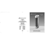
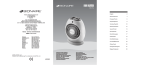
BASF40WIUK04EM1 V1.qxd
12/20/04
GUARANTEE
PLEASE KEEP YOUR RECEIPT AS THIS WILL
BE REQUIRED FOR ANY CLAIMS UNDER THIS
GUARANTEE.
• This product is guaranteed for 3 years.
• In the unlikely event of breakdown, please
take it back to the place of purchase, with
your till receipt and a copy of this guarantee.
• The rights and benefits under this guarantee
are additional to your statutory rights which
are not affected by this guarantee.
• Holmes Products Europe undertakes within
the specific period, to repair or replace free
of charge, any part of the appliance found to
be defective provided that:
•
We are promptly informed of the
defect.
•
The appliance has not been altered in
any way or subjected to misuse or
repair by a person other than a person
authorised by Holmes Products
Europe.
• No rights are given under this guarantee to a
person acquiring the appliance second hand
or for commercial or communal uses.
• Any repaired or replaced appliance will be
guaranteed on these terms for the remaining
portion of the guarantee.
THIS PRODUCT IS MANUFACTURED TO
COMPLY WITH THE E.E.C. DIRECTIVES
73/23/EEC, 89/336/EEC AND 98/37/EEC.
4:22 PM
Page 1
®
CONTEMPORARY
STAND fan
BASF40W
Holmes Products (Europe) Ltd
1 Francis Grove
London SW19 4DT
England
Fax: +44 (0)20 8947 8272
Email: [email protected]
Website address: www.theholmesgroup.com/europe
UK - Free phone Customer Service Helpline – 0800 052 3615
9100010004571
BASF40WIUK04EM1
INSTRUCTION MANUAL
12/20/04
U.K. and IRELAND
PLEASE READ AND SAVE THESE
IMPORTANT INSTRUCTIONS
When using electrical appliances, basic safety
precautions should always be taken including
the following:
• Use the fan only for purposes described in
the instruction manual.
• To protect against electrical shock, do not
immerse the fan, plug or mains cable in
water or spray with liquids.
• Close supervision is necessary when any
appliance is used by or near children.
• Unplug from the electrical outlet when not in
use, when moving the fan from one location
to another, before putting on or taking off
parts and before cleaning.
• Avoid contact with any moving parts.
• Do not operate in the presence of explosives
and/or flammable fumes.
• Do not place the fan or any parts near an
open flame, cooking or other heating
appliance.
• Do not operate any appliance with a
damaged mains cable, plug, after the
appliance malfunctions, or has been
dropped/damaged in any manner.
• The use of attachments not recommended
or sold by the appliance manufacturer may
cause hazards.
• Do not let the mains cable hang over the
edge of a table or counter, or come into
contact with hot surfaces.
• To disconnect from the electrical supply, grip
the plug and pull from the wall outlet. DO
NOT pull on the mains cable.
• Always use on a dry, level surface.
• Do not operate without the fan grills properly
in place.
• This product is intended for household use
ONLY and not for commercial or industrial
applications.
• Should the appliance stop working, first
check the fuse in the plug (UK only) or
fuse/circuit breaker at the distribution board
is operating, before contacting the
manufacturer or service agent.
• If the supply cord or plug is damaged, it
must be replaced by the manufacturer or its
service agent or a similarly qualified person
in order to avoid hazard.
• The appliance contains no user serviceable
parts and should the product suffer damage
or breakdown it must be returned to the
manufacturer or its service agent.
•
•
•
•
4:22 PM
Page 4
Do not use outdoors.
The fan should not be operated without its
base fitted.
The fan should not be operated laying on its
side.
NOTE: Use caution when adjusting the tilt
angle of the fan head to ensure that your
finger do not get caught
ASSEMBLY INSTRUCTIONS
Please see pictures on inside back
page-(See Fig.1 and 2)
1. Fit the main pole (A) to the base (B). Align
the 4 screw holes in the base to the four
holes in the main pole (A). Fix securely with
the 4 sets of base screws, flat washers,
spring washers and nuts.
2. Unscrew the tilt-control screw (D), the tiltadjustment knob (E) and the pole locking knob
(F) around the top of the extension pole (G)
and the main pole. Slide the stand base sheath
(H) into the main pole (A).
3. Raise the extension pole (G) to its full height.
Retighten the pole locking knob (F).
4. Take the fan head assembly (I), then unscrew
locking screw (J) and small screw (K). Insert
the neck of the fan head assembly onto the
pole (G) making sure alignment of lower holes.
Ensure the tilt-control screw (D) pass through
the square hole and the extension pole (G).
Fully tighten the small screw (K) to the right top
hole, and tighten the tilt-adjustment knob (E)
with tilt-control screw (D) and locking screw (J)
to the left top hole.
5. Unscrew the rear grill mounting nut (L) from
the housing. Position the rear grill (M) over
the motor shaft (N) making certain that the
notches (O), 2 at the middle of the rear grill,
fit over the corresponding prongs (P) on the
motor housing. Please make sure the rear
grill fits securely against the motor housing.
6. Secure the rear grill in its place using the
rear grill mounting nut (L). Turn this nut
clockwise and tighten firmly.
7. Remove the protective sleeve from the motor
shaft.
8. Slide the fan blade (Q), with the fixing screw
(R) facing towards the rear grill, firmly onto
the motor shaft (N), aligning the screw with
the flat part on the motor shaft.
9. Position the locking screw (R) over the flat
on the motor shaft. Tighten the screw into
the side hole of the fan blade, against the
motor shaft, until both the blade and screw
are secure.
10. Centre the front grill (S) by aligning the
Bionaire® logo on the logo plate so that it is
horizontal and parallel with the floor. Then,
holding the front grill against the rear grill,
hook the top of the grill ring (T) over the top
of the rear grill. Gently push the two parts of
the grill together until the clips around the
grill ring (T) snap into position, holding the
grills together. The grill ring must fit evenly
around the front and rear grills. If it does not,
remove the front grill and check the
alignment of the ring on the front grill.
11. Secure the guard using the screw (U),
washer (V) and clip (W) by inserting the
screw, from the front, through the hole in the
bottom of the guard ring. From the back, put the
washer and clip, which has a threaded hole,
onto the screw, ensuring the clip is the correct
way to fit into the recess on the fan ring. Tighten
the screw fully but do not overtighten.
OPERATING INSTRUCTIONS (See fig 1)
1. Set the fan base on a dry level surface.
2. Make sure the Speed Control is in the OFF
(0) position. Speed Control (X) is located on
the fan motor housing.
3. Plug the cord into a suitable outlet.
4. The SPEED is adjusted by turning the
Speed Control (X) to the desired setting:
0
- Off
I
- Low
II
- Med
III
- High
ADJUSTMENT INSTRUCTIONS
Tilt adjustment
1. To change the tilting angle of the fan head,
simply loosen the tilt-adjustment knob (E).
2. Move the fan head to the desired angle and
firmly tighten the tilt-adjustment knob (E) to
lock into place.
Height adjustment
Follow these instructions to adjust the height of
the fan.
1. Turn the pole locking knob (F) anticlockwise
to loosen the pole.
2. Adjust the pole (G) to the desired height and
firmly tighten the locking knob in a clockwise
direction.
Oscillation adjustment
The OSCILLATION control (Y) is located on the
top of the fan motor housing. To start oscillation,
push the control knob down. To stop oscillation,
pull the control knob up.
CLEANING AND MAINTENANCE
• Always unplug the fan before cleaning or
disassembly.
• Do not allow water to drip on or into the fan
motor housing.
FAN STORAGE
When storing your fan in the off season, it is
important to keep it in a safe dry location. It is
important to protect the fan from dust.
WE STRONGLY RECOMMEND USING THE
ORIGINAL BOX FROM PURCHASE.
FITTING A REPLACEMENT PLUG
FOR U.K. AND IRELAND ONLY
If the plug is not suitable for the socket outlets in
your home, it can be removed and replaced by a
plug of the correct type. Please refer to
"Installation of a plug" below.
Installation of a plug Applicable to U.K.
and Ireland.
WARNING - THIS APPLIANCE MUST BE
EARTHED.
The wires in the mains lead are coloured as such:
GREEN AND YELLOW - EARTH
BROWN
- LIVE
BLUE
- NEUTRAL
Please note that the colour of these mains wires
may not correspond with the colour markings
that identify the terminals in your plug.
Please proceed as follows:
The wire which is coloured GREEN AND
YELLOW must be connected to the terminal
which is marked with the letter 'E' or by the earth
symbol
or coloured GREEN AND YELLOW.
The BROWN coloured wire must be connected
to the terminal, which is marked with the letter
"L" or is coloured RED.
The BLUE coloured wire must be connected to
the terminal, which is marked with the letter "N"
or is coloured BLACK.
3 amp
BASF40WIUK04EM1 V1.qxd
NOTE: If the terminals in the plug are not marked
or if you are unsure or in doubt about the installation
of the plug please contact a qualified electrician.
If a 13A 3-pin plug is fitted, it must be an ASTA
approved plug, conforming to BS1363 standard.
Replacement 3A fuses must be BSI or ASTA
BS1362 approved.
BASF40W
Figue 1
Figue 2