1
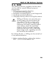
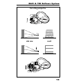
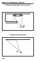
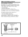
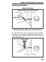
SHIFT & TILT
BELLOWS SYSTEM
Instruction Manual
as of: May 1995
ALL ARTWORK, PICTURES AND TEXTS ARE COVERED BY OUR COPYRIGHT. THEY MUST NOT BE COPIED FOR REPRODUCTION (E.G. ON
CD-ROM DISKS OR INTERNET-SITES) OR USED IN THEIR ENTIRE FORM
OR IN EXCERPTS WITHOUT OUR PREVIOUS WRITTEN AGREEMENT.
IF YOU ARE DOWNLOADING PDF-FILES FROM OUR INTERNET HOMEPAGE FOR YOUR PERSONAL USE, MAKE SURE TO CHECK FOR UPDATED
VERSIONS. WE CANNOT TAKE ANY LIABILITY WHATSOEVER FOR
DOWNLOADED FILES, AS TECHNICAL DATA ARE SUBJECT TO
CHANGE WITHOUT NOTICE.
lock for lens rotation
mark for lens rotation
lens rotation
scale for tilting
lock for tilting
scale for shifting
index pin
shifting
tilting
support rod clamp
scale for swinging
lock for focus
swinging
support rod clamp
focus-knob
adapter for 15 mm support rods
support rod clamp
note: magnification scales refers to
projection aperture 1:1.85
(width = 21mm/ 0.825")
1. Place scale in object plane
2. Align arrow with left edge of the frame
3. Magnification ratio and the corresponding
exposure increase can be read off
at the right edge of the frame
exposure increase in stops
4 3
21/2
2
1 2/3
1 1/3
3/
4
1
2
1
/3
1
/2
/3
align with left edge of the frame
4:1 2:1
1:1
1:2
1:3
1:4
1:5
magnification ratio
1:6
1:7
1:8
Shift & Tilt Bellows System
1. Safety Specifications
Warnings
Danger of injury
or equipment damage possible!
General Safety Specifications
Due to the flexible bellows design,
adjustments are possible which surpass
the technical possibilities of the attached
lens. Optically, extreme settings may
cause vignetting. Mechanically, some
lenses may collide with the bellows unit
due to their design. All settings must
therefore be executed with the
necessary caution.
• In order to ensure optimal performance, it is
essential that you acquaint yourself with this
instruction manual.
• Assembly and initial operation should be
carried out only by persons who are familiar
with the equipment!
• Repairs should be carried out only by authorized service centers!
• Only use original ARRI replacement parts and
accessories!
1
Shift & Tilt Bellows System
Important Notes
• Avoid operational errors!
• Following shift and tilt adjustments check the
viewfinder at the chosen T-stop to avoid
unwanted vignetting! In case of doubt a film
test should be shot.
• Use lens caps to avoid damage!
• Clean optical surfaces only with a lens brush
or a clean lens cloth! In case of solid dirt
moisten a lens cloth with pure alcohol.
• Do not use solvents for cleaning!
• Do not remove any screws which are secured
with paint!
Product Specifications
In case of inquiries or when ordering parts, please
advise product designation and serial number.
Explanation of the Symbols in the
Instruction Manual
➪ photo indicates objects which are shown in
the photograph on the fold-out page.
2
Shift & Tilt Bellows System
2. Contents
1. Safety Specifications ...................... 1
Warnings ............................................... 1
General Safety Specifications ................... 1
Important Notes ...................................... 2
Product Specifications .............................. 2
Explanation of the Symbols....................... 2
2. Contents ............................................. 3
3. General Description ........................ 4
4. Setting Up ......................................... 6
4.1. Attaching the Support Rod Adapter .... 6
4.2. Mounting the Bellows Unit ................. 7
4.3. Attaching the Lens ............................ 8
4.4. Setting the Working Position
of the Shift & Tilt System ........................... 9
5. Operation ........................................ 11
5.1. Focusing ....................................... 11
5.2. Setting the Working Aperture ........... 12
5.3. Shift .............................................. 13
Working Examples (Shift) ....................... 14
5.4. Tilt ................................................ 17
Scheimpflug Condition ........................... 18
Working Examples (Tilt) .......................... 19
6. Technical Data ................................ 20
7. Order Numbers .............................. 23
3
Shift & Tilt Bellows System
3. General Description
The ARRI Shift & Tilt bellows system comprises a
bellows unit as well as a set of lenses that cover
a significantly larger image area than is required
to cover the conventional format area on film.
The lenses are attached to the bellows unit via a
bayonet mount. The bellows unit is attached to
the camera with the standard PL-Mount.
The flexible bellows allows the attached lens to be
• shifted parallel to the film plane
• rotated around its optical axis and
• tilted.
This opens up creative possibilities that go far beyond those given by the focus and iris adjustments
of conventional lenses.
Some applications are:
Shift
• Eliminating perspective distortion in
architectural photography;
• Avoiding unwanted reflections;
• Excluding unwanted objects in the foreground;
• Changing framing without moving the camera;
Tilt
• Free adjustment of a focus plane,
i. e. focusing on a plane
that is not parallel to the film plane;
• Isolating a particular subject area
with a specifically chosen focus plane,
as well as combinations of shift and tilt.
4
Shift & Tilt Bellows System
Because of the bellows extension, the system can
also be used for close-up and macro cinematography.
The bellows unit is particularly robust and precise.
Corresponding operating elements are color-coded.
All adjustments are carried out via transmissions.
An index scale facilitates the exact duplication of
chosen settings. The focusing knob features a white
marking disk on which focus positions can be individually marked, as well as a connection for
mechanical remote controls.
The lenses were specifically designed for this application. The bayonet mount facilitates quick lens
changes. The double aperture scales, located opposite each other, are calibrated in T-stops and are
easily readable from the side. Uniform design, a
consistent front diameter of 87 mm and the geared
iris ring offer further user-comfort.
The system can be used with both 35 and 16 mm
cameras.
5
Shift & Tilt Bellows System
4. Setting Up
4.1. Attaching
the Support Rod Adapter
The bellows unit can be used with 19 mm as well
as with 15 mm support rods. An appropriate
adapter ➪ photo is available for each support
rod diameter.
• Undo the four screws located at the bottom of
the currently mounted adapter.
• Replace with desired adapter.
• Fasten the adapter with the four screws located
at the bottom.
6
Shift & Tilt Bellows System
4.2. Mounting
the Bellows Unit
• Ensure that the support rod clamps on the
adapter are loosened.
• Turn the focusing knob ➪ photo clockwise to
its end stop.
• Ensure that all shift and tilt adjustments ➪ photo
are in their neutral (centered) positions.
• Slide the bellows unit onto the support rods.
• Turn the bayonet ring of the camera’s PL-receptacle counterclockwise as far as it will go
and remove the protective cap.
Never put your fingers into the lens
mount receptacle.
• Push the PL-mount of the bellows unit into the
lens mount receptacle without catching it at the
edges. One of the four slots on the flange must
fit over the index pin.
• Pull the bayonet ring on the camera clockwise
to tighten. Do not over-tighten.
The final position of the bellows unit on the support
rods is set after attaching the desired lens.
7
Shift & Tilt Bellows System
4.3. Attaching the Lens
• Pull tight the clamp for lens rotation ➪ photo.
• Turn the bayonet ring of the unit’s lens mount
receptacle counterclockwise as far as it will go.
• Push the lens into the lens mount receptacle
without catching it at the edges. One of the
four slots on the lens mount must fit over the
index pin ➪ photo.
• Press the lens flat onto the lens mount receptacle
and pull the bayonet ring clockwise to tighten.
Do not over-tighten.
8
Shift & Tilt Bellows System
4.4. Setting
the Working Position of
the Shift & Tilt System
• Open the iris of the lens all the way.
• Ensure that the focusing knob ➪ photo
is turned clockwise to its end stop.
• Slide the entire bellows unit on the support
rods until the most distant relevant element of
the image is in focus. Check focus with the
camera’s viewfinder.
• Subsequently, slide the bellows unit somewhat
closer to the camera body and clamp into
position on the support rods.
9
Shift & Tilt Bellows System
S
D
object plane
film plane
Maximum Magnification
Lens
max. reproduction-ratio
Distance
lens to
Distance
filmplane to
approx.
object
in mm/inches
(S)
object
in m/inches
(D)
T3.8/18mm
1:1.8
0/0
0.13/ 0'5"
T2.8/20mm
T4/24mm
T2.8/28mm
T2.8/35mm
1:1.5
1:1.6
1.1:1
1:1.1
0/0
0/0
5/ 1/5"
0.13/ 0'5"
0.18/ 0'7"
0.17/ 0'61/2"
T2.8/45mm
T3.5/60mm
1:1.25
1:1.8
10/ 2/5"
20/ 3/4"
100/ 4"
0.17/ 0'61/2"
0.20/ 0'8"
0.29/ 1'
T1.9/80mm
T2.8/90mm
T2/110mm
1:2.4
1:2.5
1:3.2
180/ 7"
240/ 91/2"
400/ 153/4"
0.37/ 1'23/4"
0.42/ 1'41/2"
T2.8/150mm
1:4.5
820/ 321/3"
10
0.58/ 1'11"
1.0/ 3'4"
Shift & Tilt Bellows System
5. Operation
5.1. Focusing
The focusing knob on the bellows unit ➪ photo
is used for focusing. Because of the adjustable
bellows, an extended close-focus range is available. The corresponding magnification ratios are
listed in the table on page 10.
Attention: Because of the extension of
the bellows during close-focusing an
appropriate exposure compensation is
necessary.
See under Section
5.2. Setting the Working Aperture
A scale for determining the reproduction
ratio and the exposure compensation is
printed on the back fold-out page.
• Always check focus in the camera’s viewfinder
following shift or tilt adjustments
11
Shift & Tilt Bellows System
5.2. Setting the
Working Aperture
The Shift & Tilt System allows the full image circle
of the lens to be utilized. Because of this however,
there is a certain risk that the difference in illumination between the center and the edge of the
image will become visible. According to the cos4 Θ−
law, a difference in exposure of up to two stops
can result.
Attention: Check the viewfinder image
for vignetting!
In the close-focus range, a loss of light results from
the bellows extension. The approximate values for
exposure compensation are listed in the following
table. See also the scale on the back pull-out page.
Attention: Because of the extension of
the bellows during close-focusing an
appropriate exposure compensation is
necessary.
Exposure Compensation
Reproduction Ratio
Open Iris by approx.
6:1
51/2 Stops
4:1
41/2 Stops
2:1
3 Stops
1:1
2 Stops
1:1.5
11/2 Stops
1:2
11/4 Stops
1:2.5
1 Stop
3
1:3.5
/4 Stop
2
1:4.5
/3 Stop
1
1:6.5
/2 Stop
12
Shift & Tilt Bellows System
5.3. Shift
The shifting of the lens parallel to the film plane
can be used for several different purposes,
among them:
• Eliminating perspective distortion
in architectural photography;
• Excluding unwanted objects in the foreground;
• Avoiding unwanted reflections;
• Changing framing without moving the camera.
Shifting of the lens can cause the composed image to be positioned at the
very edge of the lens’s image circle,
which in turn can lead to vignetting.
Following shift and/or aperture adjustments always check the viewfinder
image to avoid unwanted vignetting.
Note also that even with a sufficiently
large image circle, vignetting can also
be caused by the matte-box.
By rotating the lens, a shifting can be carried out
in any desired direction.
• Before rotating the lens, release the rotation
lock ➪ photo on the bellows unit.
13
Shift & Tilt Bellows System
Working Examples
Changing framing without moving the camera
2:
shi
ftin
g
ing
1:
image area
image circle
14
olv
rev
Shift & Tilt Bellows System
Correcting perspective
side view
result
15
Shift & Tilt Bellows System
Excluding unwanted objects in the foreground
Avoiding unwanted reflections
16
Shift & Tilt Bellows System
5.4. Tilt
With lenses that are rigidly fixed to the camera
body, the plane in the subject area that is in focus
is parallel to the film plane. If the lens is tilted with
the Shift & Tilt System, this focus plane is displaced
correspondingly. The bellows unit can be adjusted
in two axes (“tilt” and “swing”) simultaneously, thus
allowing the focus plane to be angled in two
directions (up/down, left/right).
Because of this, the Shift & Tilt System enables
• free adjustment of a focus plane,
i. e. focusing on a plane that is not parallel
to the film plane or
• isolating a particular subject area
with a specifically chosen focus plane.
Tilting or swinging the lens can cause the
composed image to be positioned at the
very edge of the lens’s image circle, which
in turn can lead to vignetting. Following
tilt or swing and/or aperture adjustments
always check the viewfinder image to
avoid unwanted vignetting.
Note also that even with a sufficiently
large image circle, vignetting can also
be caused by the matte-box.
• Before tilting or swinging the lens, release the
corresponding locks ➪ photo on the bellows
unit.
17
Shift & Tilt Bellows System
Scheimpflug Condition
By tilting the lens it is possible to adjust a focus
plane that is not parallel to the film plane. The
Scheimpflug Condition establishes that a plane
in the subject area will be in focus when
• the film plane,
• the lens plane and
• the focus plane in the subject area
all intersect in one line. This plane will then be
completely in focus, even at maximum aperture.
The depth of field of a lens depends on
• the focal length of the lens,
• the set working aperture and
• the distance a which the lens is focused.
When the lens is tilted or swung, the depth of
field is displaced along with the focus plane.
standard-situation without shift & tilt system
depth of field
standard lens
lens plane
object plane
18
film plane
Shift & Tilt Bellows System
Working Examples
Setting a focus plane
settings according to the Scheimpflug condition
object plane
lens plane film plane
depth of field
Isolating a particular subject area with selective focus
By setting the lens plane against the Scheimpflug
Condition, an extremely small depth of field can be
achieved. This can be used for optically isolating
individual objects.
object plane depth of field
lens plane film plane
19
Shift & Tilt Bellows System
6. Technical Data
Bellows Unit
Mount camera side: .......... PL-Mount
Mount lens side: .............. Bayonet-type mount
Support: ....................... Adapter for 19 and 15 mm
support rods
Shiftadjustment: .............. +/- 10 mm (3/8“) displacement
(scale division = 1 mm)
Rotation: ...................... 360 degrees
Tiltadjustment: ................ horizontal +/- 10 degrees
(scale division = 1 degree)
vertical +/- 10 degrees
(scale division = 2 degrees)
Focusadjustment: ............. 30 mm (1 1/4“)
Weight: ........................ approx. 1100 g (2 1/2 lb.)
w/ adapter, w/o lens
Options
• PL-Adapter, e. g. for using the ARRIMACRO-lenses in the
macro range.
• Retro-Adapter, for using the lenses in the retrofocusposition for extreme magnification.
20
(1.7")
87 mm
2.8…22
(1.52")
95 mm
3.8…22
330 / 0.72
59
46
61
35
Front diameter
T-Stop scale
Weight [g/lb.]
Lens angle [degrees]
TV horizontal
TV vertical
1.85:1 horizontal
1.85:1 vertical
47
27
46
35
480 / 1
(2.29")
87 mm
4…22
9
58.2 mm
24/T4
24 mm
1:3.5
11
41
23
40
30
400 / 0.88
(2.29")
87 mm
2.8…22
10
58.2 mm
28/T 2.8
28 mm
1:2.8
12
33
18
32
25
300 / 0.66
(2.29")
87 mm
2.8…32
7
58.2 mm
35/T 2.8
35 mm
1:2.8
7
Note: the values above refer to standard 35mm format, 1.85:1 projected image and TV transmitted image
55
32
54
42
350 / 0.77
9
43.2 mm
10
38.6 mm
No. of lens groups
Image circle diameter
20/T 2.8
20 mm
1:2.8
11
18/T 3.8
18 mm
1:3.5
11
Focal length
Max. aperture
No. of lens elements
26
14
25
19
500 / 1.1
(2.29")
87 mm
2.8…22
9
58.2 mm
45/T2.8
45 mm
1:2.8
10
Shift & Tilt Bellows System
21
Shift & Tilt Bellows System
1,85:1 horizontal
1,85:1 vertical
Front diameter
T-Stop scale
Weight [g / lb.]
Lens angle [degrees]
TV horizontal
TV vertical
No. of groups
Image circle diameter
Max. aperture
No. of lens elements
Focal length
20
11
19
14
(2.29")
87 mm
3.5…22
590 / 1.3
7
58.2 mm
1:3,5
7
60/T 3.5
60 mm
15
8
14
11
(2.29")
87 mm
1.9…22
510 / 1.12
6
58.2 mm
1:1,9
7
80/T 1.9
80 mm
13
7
13
10
(2.29")
87 mm
2.8…22
440 / 0.9
5
58.2 mm
1:2,8
6
90/T2.8
90 mm
11
6
10
8
(2.29")
87 mm
2…16
780 / 1.75
6
58.2 mm
1:2
7
110/T2
110 mm
8
4
8
6
(2.29")
87 mm
2.8…22
680 / 1.5
4
58.2 mm
1:2,8
5
150/T2.8
150 mm
Note: the values above refer to standard 35mm format, 1.85:1 projected image and TV transmitted image
22
Shift & Tilt Bellows System
7. Order Numbers
Shift & Tilt System .......................................... K0.52001.0
Bellows-Set comprising
Bellows unit .................................................. K2.52009.0
Adapter 19 mm ............................................. K2.52008.0
Adapter 15 mm ............................................. K2.52004.0
Lens 24 mm/T4 ............................................. K2.52010.0
Lens 45 mm/T2.8 .......................................... K2.52011.0
Lens 90 mm/T2.8 .......................................... K2.52012.0
Lens 110 mm/T2 ........................................... K2.52013.0
optional
Lens 18 mm/T3.8 .......................................... K2.52031.0
Lens 20 mm/T2.8 .......................................... K2.52018.0
Lens 28 mm/T2.8 .......................................... K2.52033.0
Lens 35 mm/T2.8 .......................................... K2.52032.0
Lens 60 mm/T3.5 .......................................... K2.52022.0
Lens 80 mm/T1.9 .......................................... K2.52017.0
Lens 150 mm/T2.8 ........................................ K2.52019.0
PL-Adapter .................................................... K2.52020.0
Retro-Adapter ................................................ K2.52021.0
Flexible Shaft (for Shift, Tilt, Rotation) ............... K2.34890.0
Focus lever .................................................... K2.32730.0
Flexible Shaft (for Focus) ................................. K2.32731.0
Flexible Shaft (for Focus), short ........................ K2.34100.0
23
ARRI Service
ARRI SERVICE
Germany ................. Arnold & Richter Cine Technik
Türkenstraße 89
D-80799 München
phone: (089) 3809-0
fax: (089) 3809-1244
fax service: (089) 3809-1793
E-mail service: [email protected]
USA .......................... ARRI USA
617, Route 303
Blauvelt, New York 10913
phone: (914) 353 14 00
fax: (914) 425 12 50
E-mail: [email protected]
ARRI USA
600 North Victory Blvd.
Burbank, California 91502
phone: (818) 841 70 70
fax: (818) 848 40 28
E-mail: [email protected]
GB ............................ ARRI (GB) Ltd.
The Movie House
1-3 Airlinks, Spitfire Way
phone: (0208) 848 88 81
fax: (0208) 561 13 12
E-mail: [email protected]
ARRI Service
Italy .......................... ARRI ITALIA S.R.L.
Viale Edison 318
20099 Sesto S. Giovanni (Milano)
Tel.: (02) 26 22 71 75
Fax: (02) 242 16 92
E-mail: [email protected]
ARRI ITALIA S.R.L.
Via Placanica, 97
00040 Morena (Roma)
phone: (06) 79 89 02 02
fax: (06) 79 89 02 39
Canada .................... ARRI Canada Ltd.
415 Horner Avenue, Unit 11
Etobicoke, Ontario
Canada M8W 4W3
phone: (416) 255 33 35
fax: (416) 255 33 99
E-mail: [email protected]
© ARRI/KVW
Specifications subject to change without notice
Printed in Germany
Ident-No. for Manual:
K5.43422.0
available languages
German
English
ARNOLD & RICHTER
CINE TECHNIK
TÜRKENSTR. 89 • D-80799 MÜNCHEN • TEL. (089) 3809-0
FAX (089) 3809 - 1244 • http://www.arri.de


![Overview DR120 Service manual [v00]](http://vs1.manualzilla.com/store/data/006012884_1-f54ceab96779dba42a616edbeea41727-150x150.png)