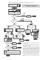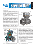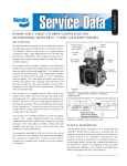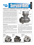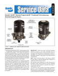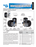
1
SD-01-700 BENDIX® BA-922® COMPRESSOR DESCRIPTION The function of the air compressor is to provide and maintain air under pressure to operate devices in the air brake systems. The Bendix® BA-922® compressor is a two cylinder, reciprocating compressor with a rated displacement of 31.6 cubic feet per minute at 1250 RPM. The compressor consists of a water-cooled cylinder head, cooling plate, valve plate assembly, and an integral air cooled crankcase and cylinder block. The cast aluminum cylinder head contains the required air and water ports as well as two unloader pistons. The cast aluminum cooling plate provides added cooling and is located between the cylinder head and valve plate assemblies. The valve plate assembly consists of laminated, brazed steel plates which incorporate various valve openings and channels for conducting air and engine coolant into and out of the cylinder head. The discharge valves are part of the valve plate assembly. The cylinder head, with the cooling and valve plates, comprise a complete cylinder head assembly. The cast iron crankcase and cylinder block assembly houses the pistons, connecting rods, crankshaft and related bearings. While not all compressors and charging systems are equipped with an optional discharge line safety valve, this component is recommended. The discharge line safety valve is installed in the cylinder head – or close to the compressor discharge port – and protects against over pressurizing the compressor in the event of a discharge line freeze up or blockage. OPERATION Safety Valve Cylinder Head Valve Plate Assembly Crankcase and Cylinder Block FIGURE 1 - BENDIX® BA-922® COMPRESSOR Delivery Port Air Intake Unloader (2) Unloader Port Discharge Reed Valves Cooling Plate Piston The compressor is driven by the vehicle engine and functions continuously while the engine is in operation. Actual compression of air is controlled by the compressor unloading mechanism operating in conjunction with a governor. Crankshaft Piston Rod FIGURE 2 - BENDIX® BA-922® COMPRESSOR (CUT-AWAY) Caterpillar® Detroit Diesel® FIGURE 3 - TYPICAL COMPRESSOR DRIVE FLANGES AIR INTAKE (LOADED) During the piston down stroke, a vacuum is created in the cylinder bore above the piston. The vacuum causes the inlet reed valve to flex open. Atmospheric air flows through the open inlet valve and fills the cylinder bore above the piston. Detroit Diesel® John Deere® cavity and into the other cylinder. A small amount of air moves out of the inlet port. On the piston down stroke (TDC to BDC), air flows in the reverse direction; from the other cylinder through the unloader piston to the inlet cavity, past the unseated unloader piston and into the cylinder bore. Governor Unloader Port Air Dryer AIR COMPRESSION (LOADED) When the piston reaches approximately bottom dead center (BDC), the inlet reed valve closes. Air above the piston is trapped by the closed inlet reed valve and is compressed as the piston begins to move toward top dead center (TDC). When air in the cylinder bore reaches a pressure greater than that of the system pressure, the discharge reed valves open and air flows into the discharge line and air brake system. Reservoir Port Compressor Supply Reservoir FIGURE 4 - BENDIX® BA-922® COMPRESSOR UNLOADER SYSTEM Air, during the compression stroke, flows into the hollow center of the unloader piston through an opening in the end of the piston. Compressed air acts on the interior surfaces of the unloader piston and, along with the unloader piston spring, holds the unloader piston against its seat on the valve plate. See Figure 6. Air Discharge Port NON-COMPRESSION OF AIR (UNLOADED) Cooling Plate When air pressure in the supply reservoir reaches the cut-out setting of the governor, the governor delivers system air to the compressor unloader port. Air entering the unloader port acts on the unloader piston, causing it to move away from its seat on the valve plate assembly. When the unloader piston is unseated a passage is opened between the cylinder bore, the air inlet cavity in the cylinder head, and the other cylinder. Air compression ceases. See Figure 7. As the piston moves from bottom dead center (BDC) to top dead center (TDC), air in the cylinder bore flows past the unseated unloader piston, into the cylinder head inlet 2 Air Inlet Port Discharge Valve Closed Valve Plate Unloader Port Unloader Piston Down & Seated Inlet Valve Open Piston Moving Down FIGURE 5 - OPERATION - LOADED (INTAKE) COOLING Air Discharge Port Air Inlet Port Discharge Valve Open Unloader Port Valve Plate Unloader Piston Down & Seated Inlet Valve Closed Piston Moving Up FIGURE 6 - OPERATION - LOADED (COMPRESSION) LUBRICATION The vehicle's engine provides a continuous supply of oil to the compressor. Oil is routed from the engine to the compressor oil inlet. An oil passage in the crankshaft conducts pressurized oil to precision sleeve main bearings and to the connecting rod bearings. Spray lubrication of the cylinder bores, connecting rod wrist pin bushings, and ball-type main bearings is obtained as oil is forced out around the crankshaft journals by engine oil pressure. Oil then falls to the bottom of the compressor crankcase and is returned to the engine through drain holes in the compressor mounting flange. Unloader Piston Up & Unseated Air flowing through the engine compartment – from the action of the engine fan and the movement of the vehicle – assists in cooling the compressor. Cooling fins are part of the crankcase/cylinder block casting. Coolant flowing from the engine cooling system through connecting lines enters the head and passes through internal passages in the cylinder head and valve plate assembly and is returned to the engine. Proper cooling is important in minimizing discharge air temperatures. Figure 8 illustrates the coolant flow connections. See the tabulated technical data in the back of this manual for specific requirements. PREVENTATIVE MAINTENANCE Regularly scheduled maintenance is the single most important factor in maintaining the air brake charging system. Refer to Table A in the Troubleshooting section for a guide to various considerations that must be given to maintenance of the compressor and other related charging system components. Important Note: Review the warranty policy before performing any intrusive maintenance procedures. An extended warranty may be voided if intrusive maintenance is performed during this period. EVERY 6 MONTHS, 1800 OPERATING HOURS, OR AFTER EACH 50,000 MILES – WHICHEVER OCCURS FIRST – PERFORM THE FOLLOWING INSPECTIONS AND TESTS. AIR INDUCTION Bendix® BA-922® compressors are only permitted to be naturally aspirated: use of the engine turbocharger as an air source is not allowed. Air Inlet Port Air From Governor Unloader Port Valve Plate Unloader Piston Up & Unseated Air in Pistons Mostly Shuttles Back and Forth from One Piston to the Other During Unloaded Mode FIGURE 7 - OPERATION - UNLOADED 3 A supply of clean air is one of the single most important factors in compressor preventative maintenance. Since the Bendix® BA-922® compressor receives supply air from the engine air filter, periodic maintenance of the engine air filter is necessary. Head Bolt (6) Discharge Safety Valve Unloader Covers Coolant In or Out Inspect the compressor intake adapter, and the connecting hoses each time engine air cleaner maintenance is performed. 1. Inspect the intake hose adapters for physical damage. Make certain to check the adapters at both ends of the intake hose or tubing. 2. Inspect the intake hose clamps and tighten them if needed. 3. Inspect the intake hose or line for signs of drying, cracking, chafing and ruptures, and replace it as necessary. COMPRESSOR COOLING Inspect the compressor discharge port, inlet cavity, and discharge line for evidence of restrictions and carbon build-up. If more than 1/16" of carbon is found, thoroughly clean or replace the affected parts. Since carbon build-up generally indicates inadequate cooling, closely inspect the compressor cooling system. Check all compressor coolant lines for kinks and restrictions to flow. Minimum coolant line size is 3/8" I.D. Check coolant lines for internal clogging from rust scale. If coolant lines appear suspicious, check the coolant flow and compare to the tabulated technical data in the back of this manual. Carefully inspect the air induction system for restrictions. LUBRICATION Check the external oil supply line for kinks, bends, or restrictions to flow. Supply lines must be a minimum of 3/16" I.D. Refer to the tabulated technical data in this manual (page 10) for oil pressure minimum values. Check the exterior of the compressor for the presence of oil seepage and refer to the TROUBLESHOOTING section (page 11) for appropriate tests and corrective action. OIL PASSING All reciprocating compressors pass a minimal amount of oil. Air dyers will remove the majority of oil before it can enter the air brake system. For particularly oil sensitive systems, the Bendix® PuraGuard® system filter can be used in conjunction with a Bendix air dryer. If compressor oil passing is suspected, refer to the TROUBLESHOOTING section and TABLE A (page 13) for the symptoms and corrective action to be taken. In addition, Bendix has developed the “Bendix Air System Inspection Cup” or BASIC kit to help substantiate suspected excessive oil passing. The steps to be followed when using the 4 Inlet Port Coolant In or Out Discharge Port Governor Connection CYLINDER HEAD PORT IDENTIFICATION The cylinder head connection ports are identified with cast in numerals as follows: Atmospheric AIR IN 0 Compressed AIR OUT 21 Coolant IN or OUT 91 and 92 Governor Control 41 (Compressors with no signal line to the unloader port should have a vent installed in the port rather than a plug.) FIGURE 8 - TYPICAL BA-922® COMPRESSOR CYLINDER HEAD BASIC kit are presented in APPENDIX A at the end of the TROUBLESHOOTING section. COMPRESSOR DRIVE Check for noisy compressor operation, which could indicate excessive drive component wear. Adjust and/or replace as necessary. Check all compressor mounting bolts and retighten evenly if necessary. Check for leakage and proper unloader mechanism operation. Repair or replace parts as necessary. COMPRESSOR UNLOADER & GOVERNOR Test and inspect the compressor and governor unloader system for proper operation and pressure setting. 1. Check for leakage at the unloader port. Replace leaking or worn o-ring. 2. Make certain the unloader system lines are connected as illustrated in Figure 3. 3. Cycle the compressor through the loaded and unloaded cycle several times. Make certain that the governor cuts in (compressor resumes compressing air) at a minimum of 105 psi (cut-out should be approximately 15-20 psi greater than cut-in pressure). Adjust or replace the governor as required. 4. Note that the compressor cycles to the loaded and unloaded conditions promptly. If prompt action is not noted, repair or replace the governor and/or repair the compressor unloader. IMPORTANT NOTE Replacement air governors must have a minimum cut-in pressure of 105 psi. The cut-in pressure is the lowest system pressure registered in the gauges before the compressor resumes compressing air. Note: When comparing build-up times, be sure to make an allowance for any air system modifications which could cause longer times, such as adding air components or reservoirs. Always check for air system leakage. Compressors with no signal line to the unloader port should have a vent installed in the port rather than a plug. See the standard Air Brake System and Accessory Leakage test on Page 24 (Test 2). LEAKAGE TESTS The following compressor operating and leakage tests need not be performed on a regular basis. These tests should be performed when it is suspected that leakage is substantially affecting compressor buildup performance, or when it is suspected that the compressor is “cycling” between the load and unloaded modes due to unloader plunger leakage. Note: Leakage in the air supply system (components before the supply reservoir - such as the governor, air dryer, reservoir drain cocks, safety valve and check valves) will not be registered on the vehicle dash gauges and must be tested separately. Refer to the various maintenance manuals for individual component leakage tests, and the Bendix “Test and Checklist” published in the Air Brake System Handbook (BW5057) and on the back of the Dual Circuit Brake System Troubleshooting card (BW1396). IN-SERVICE OPERATING TESTS Cylinder Head Compressor Performance: Build-up Test Check for cylinder head gasket air leakage. This test is performed with the vehicle parked and the engine operating at maximum recommended governed speed. Fully charge the air system to governor cut-out (air dryer purges). Pump the service brake pedal to lower the system air pressure below 80 psi using the dash gauges. As the air pressure builds back up, time from when the dash air pressure gauge passes 85 to the time it passes 100 psi. The time should not exceed 40 seconds. If the vehicle exceeds 40 seconds, test for (and fix) any air leaks and then re-test the compressor performance. If the vehicle does not pass the test the second time, use the Advanced Troubleshooting Guide for Air Brake Compressors – starting on page 11 of this document – to assist your investigation of the cause(s). 1. With the engine running, lower air system pressure to 60 psi and apply a soap solution around the cylinder head. Check the gasket between the cylinder head and valve plate assembly and the reed valve/gasket between the valve plate assembly and cylinder block for air leakage. SERVICE TESTS: GENERAL Note: All new vehicles are certified using the FMVSS 121 test (paragraph S5.1.1) by the vehicle manufacturer, however the above test is a useful guide for in-service vehicles. Optional Comparative Performance Check It may be useful to also conduct the above test with the engine running at high idle (instead of maximum governed speed), and record the time taken to raise the system pressure a selected range (for example, from 90 to 120 psi, or from 100 to 120 psi, etc.) and record it in the vehicle’s maintenance files. Subsequent build-up times throughout the vehicle’s service life can then be compared to the first one recorded. (Note: the 40 second guide in the test above does not apply to this build-up time.) If the performance degrades significantly over time, you may use the Advanced Troubleshooting Guide for Air Brake Compressors, starting on page 11 of this document, to assist your investigation of the cause(s). 2. No leakage is permitted. If leakage is detected, replace the compressor or repair the cylinder head using a genuine Bendix maintenance kit available from an authorized Bendix parts outlets. Inlet, Discharge & Unloader In order to test the inlet and discharge valves and the unloader piston, it is necessary to have shop air pressure and an assortment of fittings. A soap solution is also required. 1. With the engine shut off, drain ALL air pressure from the vehicle. 2. Disconnect the inlet and discharge lines and remove the governor or its line or adapter fitting. 3. Apply 120-130 psi shop air pressure to the unloader port and soap the inlet port. Leakage at the inlet port should not exceed 50 sccm. 4. Apply 120-130 psi shop air pressure to the discharge port and then apply and release air pressure to the inlet port. Soap the inlet port and note that leakage at the inlet port does not exceed 20 sccm. If excessive leakage is noted in tests 3 or 4, replace or repair the compressor using genuine Bendix® replacements or maintenance kits available from any authorized Bendix parts outlet. 5 While it is possible to test for inlet, discharge, and unloader piston leakage, it may not be practical to do so. Inlet and discharge valve leakage can generally be detected by longer compressor build-up and recovery times. Compare current compressor build-up times with the last several recorded times. Make certain to test for air system leakage, as described above, before making a determination that compressor performance has been lost. 2. Unloader leakage is exhibited by excessive compressor cycling between the loaded and unloaded condition. 1. With service and supply system leakage below the maximum allowable limits and the vehicle parked, bring system pressure to governor cut-out and allow the engine to idle. 2. The compressor should remain unloaded for a minimum of 5-10 minutes. If compressor cycling occurs more frequently, and service and supply system leakage is within tolerance (including any leakage that may be present at the air dryer exhaust), replace or repair the compressor unloader system using a genuine Bendix maintenance kit available from authorized Bendix parts outlets. COMPRESSOR REMOVAL & DISASSEMBLY 3. 4. 5. GENERAL The following disassembly and assembly procedure is presented for reference purposes and presupposes that a rebuild or repair of the compressor is being undertaken. Several maintenance kits are available. The instructions provided with these parts and kits should be followed in lieu of the instructions presented here. MAINTENANCE KITS & SERVICE PARTS 6. 7. 8. safety glasses. Where specifically directed, the parking brakes may have to be released, and/or spring brakes caged, and this will require that the vehicle be prevented from moving by other means for the duration of these tests/procedures. Stop the engine and remove ignition key when working under or around the vehicle. When working in the engine compartment, the engine should be shut off and the ignition key should be removed. Where circumstances require that the engine be in operation, EXTREME CAUTION should be used to prevent personal injury resulting from contact with moving, rotating, leaking, heated or electrically charged components. Do not attempt to install, remove, disassemble or assemble a component until you have read and thoroughly understand the recommended procedures. Use only the proper tools and observe all precautions pertaining to use of those tools. If the work is being performed on the vehicle’s air brake system, or any auxiliary pressurized air systems, make certain to drain the air pressure from all reservoirs before beginning ANY work on the vehicle. If the vehicle is equipped with a Bendix® AD-IS® air dryer system or a dryer reservoir module, be sure to drain the purge reservoir. Following the vehicle manufacturer’s recommended procedures, deactivate the electrical system in a manner that safely removes all electrical power from the vehicle. Never exceed manufacturer ’s recommended pressures. Never connect or disconnect a hose or line containing pressure; it may whip. Never remove a component or plug unless you are certain all system pressure has been depleted. Use only genuine Bendix® brand replacement parts, components and kits. Replacement hardware, tubing, hose, fittings, etc. must be of equivalent size, type and strength as original equipment and be designed specifically for such applications and systems. Components with stripped threads or damaged parts should be replaced rather than repaired. Do not attempt repairs requiring machining or welding unless specifically stated and approved by the vehicle and component manufacturer. Cylinder Head Gasket Kit ........................................ 5014472 Unloader Kit ............................................................. 5014473 Governor Adapter Kit ............................................... 5008561 Compressor Seal Kit (crankcase) ............................ 5008559 CAT MD Seal Kit ...................................................... 5012367 CAT HD Seal Kit ...................................................... 5012369 Series 60 Seal Kit .................................................... 5012371 ST-4 Discharge Safety Valve (7/8"-14 thrd.) ...............801116 ST-4 Discharge Safety Valve (M16-1.5 thrd.) ............ 800534 9. All components shown in Figure 10 with a key number are available in kits and/or as individual service parts. 10. Prior to returning the vehicle to service, make certain all components and systems are restored to their proper operating condition. GENERAL SAFETY GUIDELINES 11. For vehicles with Automatic Traction Control (ATC), the ATC function must be disabled (ATC indicator lamp should be ON) prior to performing any vehicle maintenance where one or more wheels on a drive axle are lifted off the ground and moving. WARNING! PLEASE READ AND FOLLOW THESE INSTRUCTIONS TO AVOID PERSONAL INJURY OR DEATH: When working on or around a vehicle, the following general precautions should be observed at all times: 1. Park the vehicle on a level surface, apply the parking brakes, and always block the wheels. Always wear 6 REMOVAL In many instances it may not be necessary to remove the compressor from the vehicle when installing the various 1 2 3 4 5 6 7 10 8 9 Cylinder Head 11 Cooling Plate 11 Valve Plate Assembly 12 Crankcase & Cylinder Block 13 14 Item 1 21 31 41 51 Qty. 2 1 1 1 1 Description Unloader Cover Cap Screw Unloader Cover Unloader Cap Gasket Unloader Balance Piston Spring Crankcase Cover Item 61 71 81 91 10 Qty. 1 1 1 1 1 Description O-Ring O-Ring Unloader Piston O-Ring ST-4™ Safety Valve End Cover Item 11 12 13 14 Qty 22 12 13 13 Description Head Gasket Inlet Reed Valve/Gasket O-Ring Bottom Cover Gasket Notes: 1. Contained in Unloader Kit 5014473 2. Contained in Cylinder Head Gasket Kit 5014472 3. Contained in Seal Kits 5008559, 5008561, 5008557 & 5008558 FIGURE 9 - BENDIX® BA-922® COMPRESSOR EXPLODED VIEW OF SERVICEABLE PARTS maintenance kits and service parts. The maintenance technician must assess the installation and determine the correct course of action. These instructions are general and are intended to be a guide. In some cases additional preparations and precautions are necessary. In all cases follow the instructions contained in the vehicle maintenance manual in lieu of the instructions, precautions and procedures presented in this manual. 1. Block the wheels of the vehicle and drain the air pressure from all the reservoirs in the system. 2. Drain the engine cooling system and the cylinder head of the compressor. Identify and disconnect all air, water and oil lines leading to the compressor. 3. Remove as much road dirt and grease from the exterior of the compressor as possible. 7 4. Remove the discharge and inlet fittings, if applicable, and note their position on the compressor to aid in reassembly. Note: If a cylinder head maintenance kit is being installed, stop here and proceed to PREPARATION FOR DISASSEMBLY. If replacing the compressor continue. 5. Remove any supporting bracketing attached to the compressor and note their positions on the compressor to aid in reassembly. 6. Remove the flange mounting bolts and remove the compressor from the vehicle. 7. Inspect gear and associated drive parts for visible wear or damage. Since these parts are precision fitted, they must be replaced if they are worn or damaged. If replacing the compressor or replacing the drive gear, remove the drive gear from the compressor crankshaft using a gear puller. 8. If the compressor is being replaced stop here and proceed to "Installing The Compressor" at the end of the assembly procedure. PREPARATION FOR DISASSEMBLY 6. Remove the two bolts located in the center of the head. Gently tap the head, cooling plate and valve plate assembly with a soft mallet to break the gasket seal. Lift the cylinder head with cooling plate and valve plate assembly off the cylinder block. 7. Remove the metal reed valve/gasket (12). 8. Gently tap the head, cooling plate and valve plate assembly with a soft mallet to break the gasket seals. Then separate the cylinder head from the cooling plate and valve plate assembly and remove the gasket (11) between them. 9. Turn the aluminum cylinder head over to expose the interior portion of the head. Push the unloader piston (7) along with its o-rings (6, 8 & 9) out of the cylinder head. CRANKCASE COVER 1. Remove the four crankcase cover cap screws securing the crankcase cover to the crankcase. Using a soft mallet, gently tap the crankcase cover to break the gasket seal. Remove the crankcase cover gasket (14). Remove the balance of road dirt and grease from the exterior of the compressor with a cleaning solvent. Mark the rear end cover or end cover adapter in relation to the crankcase. It is recommended, but not specifically necessary, to mark the relationships of the cylinder head, cooling plate, valve plate assembly, crankcase and cylinder block assembly. REAR END COVER OR END COVER ADAPTER A convenient method to indicate the above relationships is to use a metal scribe to mark the parts with numbers or lines. Do not use marking methods such as chalk that can be wiped off or obliterated during rebuilding. CLEANING OF PARTS Prior to disassembly make certain that the appropriate kits and/or replacement parts are available. Refer to Figure 9 during the entire disassembly and assembly procedure. CYLINDER HEAD 1. Remove the discharge safety valve (10) from the cylinder head. 2. To restrain the spring force exerted by balance piston spring (5), hold the unloader cover (2) in place while removing the two unloader cover cap screws (1). Carefully release the hold on the unloader cover until the spring force is relaxed, then remove the unloader cover (2). 3. Remove the unloader cover gasket (3). 4. Remove the balance piston (4) and its spring (5) from the cylinder head. 5. Remove the six hex head bolts and washers from the cylinder head. 8 1. Remove the four end cover cap screws that secure the rear end cover or end cover adapter to the crankcase. 2. Remove the rear end cover or end cover adapter from the crankcase. Remove the o-ring seal (13) from the end cover. GENERAL All parts should be cleaned in a good commercial grade of solvent and dried prior to inspection. CYLINDER HEAD 1. Carefully remove all gasket material adhering to the aluminum cylinder head, steel valve plate assembly and cast iron cylinder block. Make certain not to deeply scratch or mar the gasket surfaces. Pay particular attention to the gasket surfaces of the aluminum head. 2. Remove carbon deposits from the discharge and inlet cavities of the cylinder head and valve plate assembly. They must be open and clear in both assemblies. Make certain not to damage the aluminum head. 3. Remove rust and scale from the cooling cavities and passages in the head and valve plate assembly and use shop air to clear debris from the passages. 4. Check the threads in all cylinder head ports for galling. Minor chasing is permitted. 5. Make certain the unloader vent passage under the unloader cover (2) in the head is open and free of debris. INSPECTION OF PARTS CYLINDER HEAD & VALVE PLATE 1. Carefully inspect the cylinder head gasket surfaces for deep gouges and nicks. If detected, the compressor must be replaced. 2. Carefully inspect the valve plate assembly gasket surfaces for deep gouges and nicks. Pay particular attention to the metal gasket surface. A metal gasket (12) is used between the valve plate assembly and the cylinder block. This surface must be smooth and free of all but the most minor scratching. If excessive marring or gouging is detected, the compressor must be replaced. 3. Inspect the cylinder head for cracks or damage. With the cylinder head and head gasket secured to the valve plate assembly, apply shop air pressure to one of the coolant ports with all others plugged, and check for leakage by applying a soap solution to the exterior of the head. If leakage is detected in the cylinder head casting, replace the compressor. END COVER OR END COVER ADAPTER Check for cracks and external damage. Check the crankshaft main bearing surface in the end cover or end cover adapter, check for excessive wear and flat spots and replace the end cover if necessary. Check for galling of the oil port threads and replace the end cover or end cover adapter if necessary. Minor thread chasing is permitted but do not “recut” the threads if they are badly damaged. CYLINDER BLOCK 1. Check the cylinder head gasket surface on the cylinder block for nicks, gouges, and marring. A metal gasket is used to seal the cylinder head to the cylinder block. This surface must be smooth and free of all but the most minor scratching. If excessive marring or gouging is detected, the compressor must be replaced. DISCHARGE LINE 1. Inspect the discharge line for kinks, damage, or carbon deposits. Replace as necessary. See the advanced troubleshooting guide for more information. ASSEMBLY General Note: All torques specified in this manual are assembly torques and typically can be expected to fall off after assembly is accomplished. Do not re-torque after initial assembly torques fall unless instructed otherwise. A compiled listing of torque specifications is presented on page 11 of this manual. INCH POUNDS TO FOOT POUNDS To convert inch pounds to foot pounds of torque, divide inch pounds by 12. 12 Inch Pounds = 1 Foot Pound Example: 12 FOOT POUNDS TO INCH POUNDS To convert foot pounds to inch pounds of torque, multiply foot pounds by 12. Example: 1 Foot Pound x 12 = 12 Inch Pounds CRANKCASE COVER 1. Position the crankcase cover gasket (14) on either the crankcase or crankcase cover and install the crankcase cover on the crankcase using the four cap screws. "Snug" the four cap screws then torque to 62-71 inch pounds (7-8 Nm) using a crossing pattern. CRANKCASE END COVER OR ADAPTER 1. Install the end cover o-ring (13) on the crankcase end cover. 2. Orient the crankcase end cover or end cover adapter to the crankcase using the reference marks made during disassembly. Carefully install the end cover or end cover adapter in the crankcase making certain not to damage the crankshaft bearing surface in it. 3. Install the four end cover screws or studs. "Snug" the screws then tighten to 195 to 213 inch pounds (22-24 Nm) using a crossing pattern. CYLINDER HEAD 1. Note the position of the protruding alignment pins on the cylinder block. Install the metal inlet reed valve/gasket (12) over the alignment pins on the cylinder block. 2. Position the valve plate assembly on the cylinder block so that the alignment pins in the cylinder block fit into the corresponding holes in the valve plate assembly. 3. Position and install one of the metal gaskets (11) over the alignment bushings protruding from the valve plate assembly. When properly installed, the outline of the gasket matches the outline of the valve plate. 4. Install the cooling plate over the alignment bushings protruding from the valve plate assembly. Again, when properly installed, the outline of the cooling plate matches the outline of the valve plate. 5. Position and install the other metal gasket (11) over the alignment bushings protruding from the cooling plate assembly. The outline of the gasket matches the outline of the cooling plate. 6. Position and install the cylinder head over the alignment bushings protruding from the cooling plate. Note: The alignment bushings will only fit into two of the six cylinder head bolt holes. 7. Install the two center bolts and six hex head cylinder head bolts and washers and snug them, then tighten evenly to a torque of 265 to 292 inch pounds (30-33 Nm) using the pattern shown in Figure 9. 8. Install the unloader piston (7) with its pre-installed o-rings (6, 8, 9) in the cylinder head making certain not to damage them in the process. 9 9. Install the balance piston spring (5) in the unloader piston (7), then install the small diameter of the balance piston (4) through the center of the spring. 5, 11 10. Install the unloader cover gasket (3) on the cylinder head making certain the unloader vent passage and both screw holes align. 8, 14 1, 15 7,13 11. Position the unloader cover (2) on top of the balance piston (4) making certain the stamped logo is visible. 12. Press and hold the unloader cover (2) in place on the cylinder head and install both unloader cover cap screws (1). Torque the cover cap screws (1) from 62 to 71 inch pounds (7-8 Nm). INSTALLING THE COMPRESSOR 1. If the compressor was removed for replacement, install the drive components. Torque the crankshaft nut to 220 - 254 foot pounds (210-290 Nm). 2. Install any supporting bracketing on the compressor in the same position noted and marked during removal. 3. Install the gasket on the drive flange of the compressor. Make certain oil supply or return holes in the gasket are properly aligned with the compressor and engine. Gasket sealants are not recommended. Secure the compressor on the engine and tighten the mounting bolts. 4. Install the discharge, inlet and governor adapter fittings, if applicable, in the same position on the compressor noted and marked during disassembly. Make certain the threads are clean and the fittings are free of corrosion. Replace as necessary. See the Torque Specifications for various fitting sizes and types of thread on page 11 of this manual. 5. Inspect all air, oil, and coolant lines and fittings before reconnecting them to the compressor. Make certain o-ring seals are in good or new condition. Tighten all hose clamps. 6. Clean oil supply line. Before connecting this line to the compressor. Run the engine briefly to be sure oil is flowing freely through the supply line. 7. Before returning the vehicle to service, perform the Operation and Leakage Tests specified in this manual. Pay particular attention to all lines reconnected during installation and check for air, oil, and coolant leaks at compressor connections. Also check for noisy operation. TESTING REBUILT COMPRESSOR In order to properly test a compressor under operating conditions, a test rack for correct mounting, cooling, lubricating, and driving the compressor is necessary. Such tests are not compulsory if the unit has been carefully rebuilt by an experienced person. A compressor efficiency, or build-up test, can be run with realite ease. An engine 10 3, 9 Sequence Torque (Nm) 1 . . . . . . . . . . . 13 2 . . . . . . . . . . . 13 3 . . . . . . . . . . . 20 4 . . . . . . . . . . . 20 5 . . . . . . . . . . . 20 6 . . . . . . . . . . . 20 7 . . . . . . . . . . . 20 8 . . . . . . . . . . . 20 2, 16 4, 10 6, 12 Sequence Torque (Nm) 9 . . . . . . . . . . . 32 10 . . . . . . . . . . 32 11 . . . . . . . . . . 32 12 . . . . . . . . . . 32 13 . . . . . . . . . . 32 14 . . . . . . . . . . 32 15 . . . . . . . . . . 13 16 . . . . . . . . . . 13 FIGURE 10 - BENDIX® BA-922® COMPRESSOR HEAD BOLT TORQUE SEQUENCE lubricated compressor must be connected to an oil supply line of at least 15 psi pressure during the test and an oil return line must be installed to keep the crankcase drained. Connect to the compressor discharge port, a reservoir with a volume of 1500 cubic inches, including the volume of the connecting line. With the compressor operating at 2100 RPM, the time required to raise the reservoir(s) pressure from 85 psi to 100 psi should not exceed 5 seconds. During this test, the compressor should be checked for gasket leakage and noisy operation, as well as unloader operation and leakage. If the compressor functions as indicated, reinstall on the vehicle connecting all lines as marked in the disassembly procedure. BENDIX® BA-922® COMPRESSOR SPECIFICATIONS Typical weight ................................................................. 60 lbs. Number of cylinders ................................................................ 2 Bore Diameter ...................................... 3.622 in. (92.005 mm) Stroke ................................................... 2.125 in. (53.970 mm) Calculated displacement at 1250 RPM ..................... 31.7 CFM Flow Capacity @ 1800 RPM & 120 PSI ......................25.2 CFM Flow Capacity @ 3000 RPM & 120 PSI ......................38.4 CFM Maximum recommended RPM ................................ 3000 RPM Minimum coolant flow maximum RPM ............... 2.0 Gals./Min. Approximate horsepower required: Loaded 1800 RPM at 120 PSIG ................................... 8.73 HP Unloaded 1800 RPM .................................................... 1.96 HP Maximum inlet air temperature ........................................ 170°F Maximum discharge air temperature ............................... 350°F Minimum oil pressure required ........................................ 15 PSI Minimum oil-supply line size ...................................... 3/16" I.D. Minimum unloader-line size ....................................... 3/16" I.D. Minimum Governor Cut-out Pressure .............................120 PSI TORQUE SPECIFICATIONS Assembly Torques in inch pounds (in. Ibs.) M8x1.25-6g Cylinder Head .......... 265-292 In. Lbs. (30-33 Nm) M5x0.75-6g Unloader Cap ................... 62-71 In. Lbs. (7-8 Nm) M8x1.25-6g Governor Adapter .... 195-213 In. Lbs. (22-24 Nm) M8x1.25-6g Rear End Cover........ 195-213 In. Lbs. (22-24 Nm) M6x1.00-6g Crankcase Cover ........... 62-71 In. Lbs. (7-8 Nm) M20x2.50-6g Crankshaft Nut 1858-2567 In. Lbs. (210-290 Nm) Inlet Port Fittings 1 3/16"-12 UN-2B .......................... 575-637 In. Lbs. (65-72 Nm) M27 x 2.0 ....................................... 575-637 In. Lbs. (65-72 Nm) Discharge Port Fittings 7/8"-14 UNF-2B ............................. 460-504 In. Lbs. (52-57 Nm) M22 x 1.5 ....................................... 195-213 In. Lbs. (22-24 Nm) Water Port Fittings 3/4"-16 UNF-2B ............................. 319-245 In. Lbs. (36-39 Nm) M18 x 1.5-6g.................................. 230-257 In. Lbs. (26-29 Nm) Unloader Port Fittings 1/8"-27 NPT .............................................................. 2 - 3 TFFT1 M10 x 1.5-6g.................................. 120-145 In. Lbs. (14-16 Nm) Safety Valve Port M16 x 1.5 ....................................... 230-257 In. Lbs. (26-29 Nm) 3/4"-16 UNF-2B ............................. 319-345 In. Lbs. (36-39 Nm) 7/8"-14 UNF-2A ............................. 319-345 In. Lbs. (36-39 Nm) 1/2"-14 NPT .............................................................. 2 - 3 TFFT1 Oil Port 7/16"-20 UNF ....................................97-115 In. Lbs. (11-13 Nm) M12 x 1.5-6g.................................. 142-159 In. Lbs. (16-18 Nm) 1 Note: TFFT = Turns From Finger Tight Advanced Troubleshooting Guide for Air Brake Compressors INDEX Symptom Page Number Air Symptom Page Number Coolant Air brake charging system: Slow build (9.0) .....................................19 - 20 Doesn’t build air (10.0) .................................21 Air dryer: Doesn’t purge (14.0) ....................................22 Safety valve releases air (12.0) ...................22 Compressor: Constantly cycles (15.0) ..............................22 Leaks air (16.0) ............................................23 Safety valve releases air (11.0) ...................21 Noisy (18.0) ................................................23 Reservoir: Safety valve releases air (13.0) ...................22 Test Procedures (1) Oil Leakage at Head Gasket ........ 24 (2) System Leakage .......................... 24 (3) Compressor Discharge and Air Dryer Inlet Temperature ........... 24 (4) Governor Malfunction ................... 24 (5) Governor Control Line .................. 25 (6) Compressor Unloader .................. 25 BASIC Test Information ................ 26-28 Compressor leaks coolant (17.0)....................... 23 Engine Oil consumption (6.0) ....................................... 19 Oil Oil Test Card results (1.0) .................................. 14 Oil is present: On the outside of the compressor (2.0) ....... 15 At the air dryer purge/exhaust or surrounding area (3.0) ......................... 15 In the supply reservoir (4.0) .................. 16 - 18 At the valves (5.0) ........................................ 18 At air dryer cartridge (7.0) ............................ 19 In the ping tank or compressor discharge aftercooler (8.0)....................... 19 Maintenance & Usage Guidelines Maintenance Schedule and Usage Guidelines (Table A) ....... 13 11 Introduction to the Air Brake Charging System Powered by the vehicle engine, the air compressor builds the air pressure for the air brake system. The air compressor is typically cooled by the engine coolant system and lubricated by the engine oil supply. The compressor's unloader mechanism and governor (along with a synchro valve for the Bendix® DuraFlo 596™ air compressor) control the brake system air pressure between a preset maximum and minimum pressure level by monitoring the pressure in the service (or “supply”) reservoir. When the air pressure becomes greater than that of the preset “cut-out”, the governor controls the unloader mechanism of the compressor to stop the compressor from building air and also causes the air dryer to purge. As the service reservoir air pressure drops to the “cut-in” setting of the governor, the governor returns the compressor back to building air and the air dryer to air drying mode. As the atmospheric air is compressed, all the water vapor originally in the air is carried along into the air system, as well as a small amount of the lubricating oil as vapor. The duty cycle is the ratio of time the compressor spends building air to the total engine running time. Air compressors are designed to build air (run “loaded”) up to 25% of the time. Higher duty cycles cause conditions that affect air brake charging system performance which may require additional maintenance. Factors that add to the duty cycle are: air suspension, additional air accessories, use of an undersized compressor, frequent stops, excessive leakage from fittings, connections, lines, chambers or valves, etc. The discharge line allows the air, water-vapor and oil-vapor mixture to cool between the compressor and air dryer. The typical size of a vehicle's discharge line, (see column 2 of Table A on page 13) assumes a compressor with a normal (less than 25%) duty cycle, operating in a temperate climate. See Bendix and/or other air dryer manufacturer guidelines as needed. When the temperature of the compressed air that enters the air dryer is within the normal range, the air dryer can remove most of the charging system oil. If the temperature of the compressed air is above the normal range, oil as oil-vapor is able to pass through the air dryer and into the air system. Larger diameter discharge lines and/or longer discharge line lengths can help reduce the temperature. The discharge line must maintain a constant slope down from the compressor to the air dryer inlet fitting to avoid low points where ice may form and block the flow. If, instead, ice blockages occur at the air dryer inlet, insulation may be added here, or if the inlet fitting is a typical 90 degree fitting, it may be changed to a straight or 45 degree fitting. For more information on how to help prevent discharge line freeze-ups, see Bendix Bulletins TCH-008-021 and TCH-008-022 (see pages 30-32). Shorter discharge line lengths or insulation may be required in cold climates. The air dryer contains a filter that collects oil droplets, and a desiccant bed that removes almost all of the remaining water vapor. The compressed air is then passed to the air brake service (supply) reservoir. The oil droplets and the water collected are automatically purged when the governor reaches its “cut-out” setting. For vehicles with accessories that are sensitive to small amounts of oil, we recommended installation of a Bendix® PuraGuard® system filter, designed to minimize the amount of oil present. The Air Brake Charging System supplies the Discharge Line Optional “Ping” Tank Air Dryer compressed air for the braking system as well as other air accessories for the vehicle. The system usually consists of an air compressor, governor, discharge line, air dryer, and service reservoir. Optional Bendix® PuraGuard® System Filter or PuraGuard QC™ Oil Coalescing Filter Compressor Governor (Governor plus Synchro valve for the Bendix® DuraFlo 596™ Compressor) 12 Service Reservoir (Supply Reservoir) Reservoir Drain Table A: Maintenance Schedule and Usage Guidelines Regularly scheduled maintenance is the single most important factor in maintaining the air brake charging system. Vehicle Used for: No. of Axles Column 1 Column 2 Typical Compressors Spec'd Discharge Line (See footnote 7) I.D. Length 1/2 in. 6 ft. Column 3 Recommended Air Dryer Cartridge Replacement1 Column 4 Recommended Reservoir Drain Schedule2 Column 5 Acceptable Reservoir Oil Contents3 at Regular Drain Interval e.g. Line haul single trailer w/o air suspension, air over hydraulic brakes. 5 or less e.g. Line haul single trailer with air suspension, RV school bus. 5 or less Compressor with up to 25% duty cycle e.g. Double/triple trailer, open highway coach, (most) pick-up & delivery, yard or terminal jockey, off-highway, construction, loggers, concrete mixer, dump truck, fire truck. 8 or less Compressor with up to 25% duty cycle e.g. City transit bus, refuse, bulk unloaders, low boys, urban region coach, central tire inflation. 12 or less Bendix® Tu-Flo® 750 air compressor High Air Use Bendix® BA-921® air compressor Compressor with up to 25% duty cycle For oil carry-over control4 suggested upgrades: 5/8 in. 1/2 in. 9 ft. 9 ft. Every 3 Years For oil carry-over control4 suggested upgrades: 5/8 in. 1/2 in. 5/8 in. Recommended Every Month Max of every 90 days 12 ft. Every 2 Years 15 ft. Every Month 3/4 in. Footnotes: 1. With increased air demand the air dryer cartridge needs to be replaced more often. 2. Use the drain valves to slowly drain all reservoirs to zero psi. 3. Allow the oil/water mixture to fully settle before measuring oil quantity. 4. To counter above normal temperatures at the air dryer inlet, (and resultant oil-vapor passing upstream in the air system) replace the discharge line with one of a larger diameter and/or longer length. This helps reduce the air's temperature. If sufficient cooling occurs, the oil-vapor condenses and can be removed by the air dryer. Discharge line upgrades are not covered under warranty. Note: To help prevent discharge line freeze-ups, shorter discharge line lengths or insulation may be required in cold climates. (See Bendix BASIC test acceptable range: 3 oil units per month. See appendix A. For the BASIC Test Kit: Order Bendix P/N 5013711 12 ft. For oil carry-over control4 suggested upgrades: Bendix® BA-922®, or DuraFlo 596™ air compressor Compressor with less than 15% duty cycle Bendix® Tu-Flo® 550 air compressor Low Air Use 12 ft. BASIC test acceptable range: 5 oil units per month. See appendix A. Every Year Bulletins TCH-008-021 and TCH-008-022, included in Appendix B, for more information.) 5. For certain vehicles/applications, where turbo-charged inlet air is used, a smaller size compressor may be permissible. 6. Note: Compressor and/or air dryer upgrades are recommended in cases where duty cycle is greater than the normal range (for the examples above). 7. For correct compressor upgrades consult Bendix - Please note that because a compressor is listed in the same area of the chart does not necessarily mean that it would be a suitable candidate for upgrade purposes. For Bendix® Tu-Flo® 550 and 750 compressors, unloader service is recommended every 250,000 miles. 13 Air Brake Charging System Troubleshooting Look for: How to use this guide: Find the symptom(s) that you see, then move to the right to find the possible causes (“What it may indicate”) and remedies (“What you should do”). Review the warranty policy before performing any intrusive compressor maintenance. Unloader or cylinder head gasket replacement and resealing of the bottom cover plate are usually permitted under warranty. Follow all standard safety procedures when performing any maintenance. WARNING! Please READ and follow these instructions to avoid personal injury or death: When working on or around a vehicle, the following general precautions should be observed at all times. 1. Park the vehicle on a level surface, apply the parking brakes, and always block the wheels. Always wear safety glasses. 2. Stop the engine and remove ignition key when working under or around the vehicle. When working in the engine compartment, the engine should be shut off and the ignition key should be removed. Where circumstances require that the engine be in operation, EXTREME CAUTION should be used to prevent personal injury resulting from contact with moving, rotating, leaking, heated or electrically charged components. 3. Do not attempt to install, remove, disassemble or assemble a component until you have read and thoroughly understand the recommended procedures. Use only the proper tools and observe all precautions pertaining to use of those tools. 4. If the work is being performed on the vehicle’s air brake system, or any auxiliary pressurized air systems, make certain to drain the air pressure from all reservoirs before beginning ANY work on the vehicle. If the vehicle is equipped with a Bendix® AD-IS® air dryer system or a dryer reservoir module, be sure to drain the purge reservoir. Symptom: 1.0 Oil Test Card Results Normal - Charging system is working within normal range. Check - Charging system needs further investigation. 5. Following the vehicle manufacturer’s recommended procedures, deactivate the electrical system in a manner that safely removes all electrical power from the vehicle. 6. Never exceed manufacturer’s recommended pressures. 7. Never connect or disconnect a hose or line containing pressure; it may whip. Never remove a component or plug unless you are certain all system pressure has been depleted. 8. Use only genuine Bendix ® brand replacement parts, components and kits. Replacement hardware, tubing, hose, fittings, etc. must be of equivalent size, type and strength as original equipment and be designed specifically for such applications and systems. 9. Components with stripped threads or damaged parts should be replaced rather than repaired. Do not attempt repairs requiring machining or welding unless specifically stated and approved by the vehicle and component manufacturer. 10. Prior to returning the vehicle to service, make certain all components and systems are restored to their proper operating condition. 11. For vehicles with Automatic Traction Control (ATC), the ATC function must be disabled (ATC indicator lamp should be ON) prior to performing any vehicle maintenance where one or more wheels on a drive axle are lifted off the ground and moving. What it may indicate: What you should do: Not a valid test. Discontinue using this test. Do not use this card test to diagnose compressor "oil passing" issues. They are subjective and error prone. Use only the Bendix Air System Inspection Cup (BASIC) test and the methods described in this guide for advanced troubleshooting. The Bendix ® BASIC test should be the definitive method for judging excessive oil fouling/oil passing. (See Appendix A, on page 27 for a flowchart and expanded explanation of the checklist used when conducting the BASIC test.) Bendix® BASIC Test 14 Symptom: What it may indicate: What you should do: 2.0 Oil on the Outside of the Compressor Engine and/or other accessories leaking onto compressor. Find the source and repair. Return the vehicle to service. 2.1 Oil leaking at compressor / engine connections: (a) Leak at the front or rear (fuel pump, etc.) mounting flange. Repair or replace as necessary. If the mounting bolt torques are low, replace the gasket. (b) Leak at air inlet fitting. Replace the fitting gasket. Inspect inlet hose and replace as necessary. (c) Leak at air discharge fitting. Replace gasket or fitting as necessary to ensure good seal. (d) Loose/broken oil line fittings. Inspect and repair as necessary. (a) Excessive leak at head gasket. Go to Test 1 on page 24. (b) Leak at bottom cover plate. Reseal bottom cover plate using RTV silicone sealant. (c) Leak at internal rear flange gasket. Replace compressor. 2.2 Oil leaking from compressor: Replace compressor. (d) Leak through crankcase. Clean compressor and check periodically. (e) (If unable to tell source of leak.) (a) (c) (c) 3.0 Oil at air dryer purge/exhaust or surrounding area Head gaskets and rear flange gasket locations. Air brake charging system functioning normally. Air dryers remove water and oil from the air brake charging system. Check that regular maintenance is being performed. Return the vehicle to service. An optional kit (Bendix piece number 5011327 for the Bendix® AD-IS® or AD-IP® air dryers, or 5003838 for the Bendix® AD-9® air dryer) is available to redirect the air dryer exhaust. 15 Symptom: What it may indicate: 4.0 Oil in Supply or Service Reservoir (air dryer installed) (If a maintained Bendix PuraGuard® system filter or Bendix® PuraGuard QC™ oil coalescing filter is installed, call 1-800-AIR-BRAKE (1-800-247-2725) and speak to a Tech Team member.) ® What you should do: Maintenance (a) If air brake charging system maintenance has not been performed. That is, reservoir(s) have not been drained per the schedule in Table A on page 13, Column 4 and/or the air dryer maintenance has not been performed as in Column 3. (b) If the vehicle maintenance has been performed as recommended in Table A on page 13, some oil in the reservoirs is normal. (a) See Table A, on page 13, for maintenance schedule information. Drain all air tanks (reservoirs) into the Bendix® BASIC test cup. (Bendix kit P/N 5013711). Drain all air tanks and check vehicle at next service interval using the Bendix® BASIC test. See Table A on page 13, column 3 and 4, for recommended service schedule. Drain all air tanks into Bendix® BASIC test cup (Bendix Air System Inspection Cup). If less than one unit of reservoir contents is found, the vehicle can be returned to service. Note: If more than one oil unit of water (or a cloudy emulsion mixture) is present, change the vehicle's air dryer, check for air system leakage (Test 2, on page 24), stop inspection and check again at the next service interval. See the BASIC test kit for full details. If less than one "oil unit" of water (or water/ cloudy emulsion mixture) is present, use the BASIC cup chart on the label of the cup to determine if the amount of oil found is within the acceptable level. If within the normal range, return the vehicle to service. For vehicles with accessories that are sensitive to small amounts of oil, consider a Bendix® PuraGuard QC™ oil coalescing filter. If outside the normal range go to Symptom 4.0(c). Also see the Table A on page 13, column 3 for recommended air dryer cartridge replacement schedule. Duty cycle too high (c) Air brake system leakage. Go to Test 2 on page 24. (d) Compressor may be undersized for the application. See Table A, column 1, on page 13 for recommended compressor sizes. If the compressor is "too small" for the vehicle's role (for example, where a vehicle's use has changed or service conditions exceed the original vehicle or engine OE spec's) then upgrade the compressor. Note: The costs incurred (e.g. installing a larger capacity compressor, etc.) are not covered under original compressor warranty. If the compressor is correct for the vehicle, go to Symptom 4.0 (e). The duty cycle is the ratio of time the compressor spends building air to total engine running time. Air compressors are designed to build air (to "run loaded") up to 25% of the time. Higher duty cycles cause conditions that affect air brake charging system performance which may require additional maintenance. Factors that add to the duty cycle are: air suspension, additional air accessories, use of an undersized compressor, frequent stops, excessive leakage from fittings, connections, lines, chambers or valves, etc. 16 Symptom: 4.0 Oil in Supply or Service Reservoir* (air dryer installed) (continued) What it may indicate: What you should do: Temperature (e) Air compressor discharge and/or air dryer inlet temperature too high. Check temperature as outlined in Test 3 on page 24. If temperatures are normal go to 4.0(h). Inspect coolant line. Replace as necessary (I.D. is 1/2"). (f) Insufficient coolant flow. Inspect the coolant lines for kinks and restrictions and fittings for restrictions. Replace as necessary. (f) (e) Verify coolant lines go from engine block to compressor and back to the water pump. Repair as necessary. (g) Testing the temperature at the discharge fitting. Inspecting the coolant hoses. (g) Restricted discharge line. If discharge line is restricted or more than 1/16" carbon build up is found, replace the discharge line. See Table A, column 2, on page 13 for recommended size. Replace as necessary. The discharge line must maintain a constant slope down from the compressor to the air dryer inlet fitting to avoid low points where ice may form and block the flow. If, instead, ice blockages occur at the air dryer inlet, insulation may be added here, or if the inlet fitting is a typical 90 degree fitting, it may be changed to a straight or 45 degree fitting. For more information on how to help prevent discharge line freezeups, see Bendix Bulletins TCH-008-021 and TCH-008-022 (Appendix B). Shorter discharge line lengths or insulation may be required in cold climates. (g) Kinked discharge line shown. Other (h) Restricted air inlet (not enough air to compressor). (h) Partly collapsed inlet line shown. Check compressor air inlet line for restrictions, brittleness, soft or sagging hose conditions etc. Repair as necessary. Inlet line size is 3/4 ID. Maximum restriction requirement for compressors is 25 inches of water. Check the engine air filter and service if necessary (if possible, check the air filter usage indicator). *If a maintained Bendix® PuraGuard® system filter or Bendix® PuraGuard QC™ oil coalescing filter is installed, call 1-800-AIR-BRAKE (1-800-247-2725) and speak to a Tech Team member. 17 Symptom: 4.0 Oil in Supply or Service Reservoir* (air dryer installed) (continued) What it may indicate: What you should do: Other (cont.) (i) Poorly filtered inlet air (poor air quality to compressor). Check for leaking, damaged or defective compressor air inlet components (e.g. induction line, fittings, gaskets, filter bodies, etc.). Repair inlet components as needed. Note: Dirt ingestion will damage compressor and is not covered under warranty. Inspect the engine air cleaner. (j) Governor malfunction or setting. Go to Test 4 on page 25. (k) Compressor malfunction. If you found excessive oil present in the service reservoir in step 4.0 (b) above and you did not find any issues in steps 4.0 (c) through 4.0 (j) above, the compressor may be passing oil. Replace compressor. If still under warranty, follow normal warranty process. Note: After replacing a compressor, residual oil may take a considerable period of time to be flushed from the air brake system. Crankcase Flooding Consider installing a compressor bottom drain kit (where available) in cases of chronic oil passing where all other operating conditions have been investigated. Bendix compressors are designed to have a 'dry' sump and the presence of excess oil in the crankcase can lead to oil carryover. *If a maintained Bendix® PuraGuard® system filter or Bendix® PuraGuard QC™ oil coalescing filter is installed, call 1-800-AIR-BRAKE (1-800-247-2725) and speak to a Tech Team member. 5.0 Oil present at valves (e.g. at exhaust, or seen during servicing). Air brake system valves are required to tolerate a light coating of oil. A small amount of oil does not affect SAE J2024** compliant valves. Check that regular maintenance is being performed and that the amount of oil in the air tanks (reservoirs) is within the acceptable range shown on the Bendix® BASIC test cup (see also column 5 of Table A on page 13). Return the vehicle to service. For oil-sensitive systems, see page 12. ** SAE J2024 outlines tests all air brake system pneumatic components need to be able to pass, including minimum levels of tolerance to contamination. Genuine Bendix valves are all SAE J2024 compliant. 18 Symptom: What it may indicate: What you should do: 6.0 Excessive oil consumption in engine. A problem with engine or other engine accessory. See engine service manual. 7.0 Oil present at air dryer cartridge during maintenance. Air brake charging system is functioning normally. The engine service manual has more information. Oil shown leaking from an air dryer cartridge. Air dryers remove water and oil from the air brake charging system. A small amount of oil is normal. Check that regular maintenance is being performed and that the amount of oil in the air tanks (reservoirs) is within the acceptable range shown by the BASIC Test (see also column 5 of Table A on page 13). Replace the air dryer cartridge as needed and return the vehicle to service. 8.0 Oil in ping tank or compressor discharge aftercooler. Air brake charging system is functioning normally. Follow vehicle O.E. maintenance recommendation for these components. 9.0 Air brake charging system seems slow to build pressure. (a) Air brake charging system functioning normally. Using dash gauges, verify that the compressor builds air system pressure from 85-100 psi in 40 seconds or less with engine at full governed rpm. Return the vehicle to service. (b) Air brake system leakage. Go to Test 2 on page 24. (c) Compressor may be undersized for the application. See Table A, column 1, on page 13 for some typical compressor applications. If the compressor is "too small" for the vehicle's role, for example, where a vehicle's use has changed, then upgrade the compressor. Note: The costs incurred (e.g. installing a larger capacity compressor, etc.) are not covered under original compressor warranty. (d) Compressor unloader mechanism malfunction. Go to Test 6 on page 25. (e) Damaged compressor head gasket. An air leak at the head gasket may indicate a downstream restriction such as a freeze-up or carbon blockage and/or could indicate a defective or missing safety valve. Find blockage (go to 9.0(f) for details) and then replace the compressor. Do not reuse the safety valve without testing. See Symptom 12.0(a). 19 Symptom: What it may indicate: 9.0 Air brake charging system seems slow to build pressure. (continued) (f) Restricted discharge line. (f) Dash gauges. Kinked discharge line shown. Engine Oil Quality Inadequate oil change intervals, the formulation of the oil and/or the quality of oil filter used can all lead to poor oil quality. These can increase the rate at which carbon builds up in the discharge line. Bendix recommends oil soot (solids) be maintained at less than 3%. (g) Restricted air inlet (not enough air to compressor). (g) What you should do: If discharge line is restricted: By more than 1/16" carbon build up, replace the discharge line (see Table A, column 2, on page 13 for recommended size) and go to Test 3 on page 24. By other restrictions (e.g. kinks). Replace the discharge line. See Table A, column 2, on page 13 for recommended size. Retest for air build. Return vehicle to service or, if problem persists, go to 9.0(a). The discharge line must maintain a constant slope down from the compressor to the air dryer inlet fitting to avoid low points where ice may form and block the flow. If, instead, ice blockages occur at the air dryer inlet, insulation may be added here, or if the inlet fitting is a typical 90 degree fitting, it may be changed to a straight or 45 degree fitting. For more information on how to help prevent discharge line freezeups, see Bendix Bulletins TCH-008-021 and TCH-008-022 (Appendix B). Shorter discharge line lengths or insulation may be required in cold climates. Check compressor air inlet line for restrictions, brittleness, soft or sagging hose conditions etc. Repair as necessary. Refer to vehicle manufacturer’s guidelines for inlet line size. Check the engine air filter and service if necessary (if possible, check the air filter usage indicator). Partly collapsed inlet line shown. 20 (h) Poorly filtered inlet air (poor air quality to compressor). Check for leaking, damaged or defective compressor air inlet components (e.g. induction line, fittings, gaskets, filter bodies, etc.). Repair inlet components as needed. Note: Dirt ingestion will damage compressor and is not covered under warranty. (i) Compressor malfunction. Replace the compressor only after making certain that none of the preceding conditions, 9.0 (a) through 9.0 (h), exist. Symptom: 10.0 Air charging system doesn’t build air. What it may indicate: (a) Governor malfunction*. Go to Test 4 on page 25. (b) Restricted discharge line. See 9.0(f). (c) Air dryer heater malfunction: exhaust port frozen open. Replace air dryer heater. (d) Compressor malfunction. Replace the compressor only after making certain the preceding conditions do not exist. * Note: For the Bendix® DuraFlo 596™ air compressor, not only the governor, but also the SV-1™ synchro valve used would need to be tested. See Bulletin TCH-001-048. 11.0 Compressor safety valve releases air (Compressor builds too much air). What you should do: (a) Restricted discharge line. Damaged discharge line shown. If discharge line is restricted: By more than 1/16" carbon build up, replace the discharge line (see Table A, column 2, on page 13 for recommended size) and go to Test 3 on page 24. By other restrictions (e.g. kinks). Replace the discharge line. See Table A, column 2, on page 13 for recommended size. The discharge line must maintain a constant slope down from the compressor to the air dryer inlet fitting to avoid low points where ice may form and block the flow. If, instead, ice blockages occur at the air dryer inlet, insulation may be added here, or if the inlet fitting is a typical 90 degree fitting, it may be changed to a straight or 45 degree fitting. For more information on how to help prevent discharge line freezeups, see Bendix Bulletins TCH-008-021 and TCH-008-022 (Appendix B). Shorter discharge line lengths or insulation may be required in cold climates. (b) Downstream air brake system check valves or lines may be blocked or damaged. Inspect air lines and verify check valves are operating properly. (c) Air dryer lines incorrectly installed. Ensure discharge line is installed into the inlet of the air dryer and delivery is routed to the service reservoir. (d) Compressor safety valve malfunction. Verify relief pressure is 250 psi. Replace if defective. (e) Compressor unloader mechanism malfunction. Go to Test 6 on page 25. (f) Governor malfunction. Go to Test 4 on page 25. 21 Symptom: 12.0 Air dryer safety valve releases air. Air dryer safety valve What it may indicate: (a) Restriction between air dryer and reservoir. Inspect delivery lines to reservoir for restrictions and repair as needed. (b) Air dryer safety valve malfunction. Verify relief pressure is at vehicle or component manufacturer specifications. Replace if defective. (c) Air dryer maintenance not performed. See Maintenance Schedule and Usage Guidelines (Table A, column 3, on page 13). (d) Air dryer malfunction. Verify operation of air dryer. Follow vehicle O.E. maintenance recommendations and component Service Data information. (e) Improper governor control line installation to the reservoir. Go to Test 5 on page 25. (f) Governor malfunction. Go to Test 4 on page 25. (a) Reservoir safety valve malfunction. Verify relief pressure is at vehicle or component manufacturer's specifications (typically 150 psi). Replace if defective. (b) Governor malfunction. Go to Test 4 on page 25. (c) Compressor unloader mechanism malfunction. Go to Test 6 on page 25. (a) Air dryer malfunction. Verify operation of air dryer. Follow vehicle O.E. maintenance recommendations. (b) Governor malfunction. Go to Test 4 on page 25. (c) Air brake system leakage. Go to Test 2 on page 24. (d) Improper governor control line installation to the reservoir. Go to Test 5 on page 25. (a) A i r b r a k e c h a r g i n g s y s t e m maintenance not performed. Available reservoir capacity may be reduced by build up of water etc. Drain and perform routine maintenance per Table A, columns 3 & 4, on page 13. (b) Compressor unloader mechanism malfunction. Go to Test 6 on page 25. (c) Air dryer purge valve or delivery check valve malfunction. Verify operation of air dryer. Follow vehicle O.E. maintenance recommendations and component Service Data information. (d) Air brake system leakage. Go to Test 2 on page 24. Technician removes governor. 13.0 Reservoir safety valve releases air 14.0 Air dryer doesn’t purge. (Never hear exhaust from air dryer.) 15.0 Compressor constantly cycles (compressor remains unloaded for a very short time.) 22 What you should do: 16.0 Compressor leaks air Testing for leaks with soap solution. 17.0 Compressor leaks coolant 18.0 Noisy compressor (Multi-cylinder compressors only) What it may indicate: What you should do: (a) Compressor leaks air at connections or ports. Check for leaking, damaged or defective compressor fittings, gaskets, etc. Repair or replace as necessary. (b) Compressor unloader mechanism malfunction. Go to Test 6 on page 25. (c) Damaged compressor head gasket(s). An air leak at the head gasket(s) may indicate a downstream restriction such as a freeze-up or carbon blockage and/or could indicate a defective or missing safety valve. Find blockage (go to 9.0(f) for details) and then replace the compressor. Do not reuse the safety valve without testing. See Symptom 12.0(a). Head gaskets locations Symptom: (a) Improperly installed plugs or coolant line fittings. Inspect for loose or over-torqued fittings. Reseal and tighten loose fittings and plugs as necessary. If overtorqued fittings and plugs have cracked ports in the head, replace the compressor. (b) Damaged compressor head gasket. An air leak at the head gasket may indicate a downstream restriction such as a freezeup or carbon blockage and/or could indicate a defective or missing safety valve. Find blockage (go to 9.0(f) for details) and then replace the compressor. Do not re-use the safety valve without testing. See Symptom 12.0(a). (c) Porous compressor head casting. If casting porosity is detected, replace the compressor. (a) Damaged compressor. Replace the compressor. Other Miscellaneous Areas to Consider This guide attempts to cover most compressor system problems. Here are some rare sources of problems not covered in this guide: • Turbocharger leakage. Lubricating oil from leaking turbocharger seals can enter the air compressor intake and give misleading symptoms. • Where a compressor does not have a safety valve installed, if a partial or complete discharge line blockage has occurred, damage can occur to the connecting rod bearings. Damage of this kind may not be detected and could lead to compressor problems at a later date. 23 Tests Test 1: Excessive Oil Leakage at the Head Gasket Exterior leaks at the head gasket are not a sign that oil is being passed into the air charging system. Oil weepage at the head gasket does not prevent the compressor from building air. Look for Weepage Observe the amount of weepage from the head gasket. If the oil is only around the cylinder head area, it is acceptable (return the vehicle to service), but, if the oil weepage extends down to the nameplate area of the compressor, the gasket can be replaced. Test 2: Air Brake System and Accessory Leakage Inspect for air leaks when working on a vehicle and repair them promptly. Park the vehicle on level ground and chock wheels. Build system pressure to governor cut-out and allow the pressure to stabilize for one minute. Step 1: Observe the dash gauges for two additional minutes without the service brakes applied. Step 2: Apply the service brakes and allow the pressure to stabilize. Continue holding for two minutes (you may use a block of wood to hold the Test 3: Air Compressor Discharge Temperature and Air Dryer Inlet Temperature* Caution: The temperatures used in this test are not normal vehicle conditions. Above normal temperatures can cause oil (as vapor) to pass through the air dryer into the air brake system. This test is run with the engine at normal operating temperature, with engine at max. rpm. If available, a dyno may be used. 1. Allow the compressor to build the air system pressure to governor cut-in. 2. Pump the brakes to bring the dash gauge pressure to 90 psi. 3. Allow the compressor to build pressure from 95 to 105 psi gauge pressure and maintain this pressure range by cycling the brakes for five (5) minutes. pedal in position.) Observe the dash gauges. If you see any noticeable decrease of the dash air gauge readings (i.e. more than 4 psi, plus two psi for each additional trailer) during either two minute test, repair the leaks and repeat this test to confirm that they have been repaired. Air leaks can also be found in the charging system, parking brakes, and/or other components - inspect and repair as necessary. (* Note that only vehicles that have passed Test 2 would be candidates for this test.) 4. Then, while maintaining max rpm and pressure range, measure and record the surface temperature of the fittings: at the compressor discharge port. (T1). at the air dryer inlet fitting. (T2). Use a touch probe thermocouple for measuring the temperature. 5. See table below. 6. Retest before returning the vehicle to service. T1 T2 Compressor Air Dryer Discharge Inlet Fitting Fitting under 360°F under 200°F Temperatures are within normal range for this test, check other symptoms. Go to 4.0 (h). under 360°F over 200°F This could indicate a discharge line problem (e.g. restriction). Call 1-800-AIR-BRAKE (1-800-247-2725) and speak with our Tech Team. over 360°F __ T1 T2 Discharge Line 24 Action Compressor is running hot. Check coolant 4(f) and/or discharge line 4(g). Tests (continued) Test 4: Governor Malfunction 1. Inspect control lines to and from the governor for restrictions (e.g. collapsed or kinked). Repair as necessary. 2. Using a calibrated external gauge in the supply reservoir, service reservoir, or reservoir port of the D-2® governor, verify cut-in and cut-out pressures are within vehicle OEM specification. 3. If the governor is malfunctioning, replace it. Test 5: Governor Control Line 1. Ensure that the governor control line from the reservoir is located at or near the top of the reservoir. (This line, if located near the bottom of the reservoir, can become blocked or restricted by the reservoir contents e.g. water or ice.) 2. Perform proper reservoir drain intervals and air dryer cartridge maintenance per Maintenance Schedule and Usage Guidelines (Table A on page 13). 3. Return the vehicle to service. Test 6: Compressor Unloader Leakage Bendix ® Compressors: Park vehicle, chock wheels, and follow all standard safety procedures. Remove the governor and install a fitting to the unloader port. Add a section of air hose (min 1 ft long for a 1/2" diameter line) and a gauge to the fitting followed by a shut-off valve and an air source (shop air or small air tank). Open the shut off and charge the unloader port by allowing air pressure to enter the hose and unload the compressor. Shut off the air supply and observe the gauge. A steady reading indicates no leakage at the unloader port, but a falling reading shows that the unloader mechanism is leaking and needs to be serviced. 25 Appendix A: Information about the BASIC Test Kit (Bendix P/N 5013711) Service writer records info - including the number of days since all air tanks were drained - and fills out symptom checklist. Technician inspects items. days Bendix® Air System Inspection Cup (BASIC) Test Information START BASIC TEST Park vehicle on LEVEL ground. Chock wheels, drain air from system. Drain contents of ALL air tanks into BASIC™ cup Is there less than one unit of liquid? Vehicle OK. Return vehicle to service. YES END TEST NO Is there more than one unit of: • water, or • cloudy emulsion mixture? Cloudy emulsion mixture YES NO, only oil. Is this a transit vehicle, bulk unloader, or has more than 5 axles? YES, this is a high air use vehicle. Find the point on the label where the number of oil units meets the number of days* since the vehicle's air tanks were last drained. h Hig Low NO, this is a low air use vehicle. YES Find the point on the label where the number of oil units meets the number of days* since the vehicle's air tanks were last drained. Go to the Advanced Troubleshooting Guide to find reason(s) for presence of water h Hig Is the point above the HIGH Air Use line on the cup? Is the point above the LOW Air Use line on the cup? NO H YES Test for air leakage YES Repair leaks and return vehicle to service END TEST 26 Use Test 2: Air Leakage NO (did not know when last with the drained) Re-test ™ BASIC Test after 30 days*** END TEST * If the number of days since the air tanks were drained is unknown - use the 30 day line. ** Note: Typical air dryer cartridge replacement schedule is every 3 yrs/ 300K miles for low air use vehicles and every year/100K miles for high air use vehicles. END TEST YES, number of days was known (30 - 90 days) Replace the Compressor. If under warranty, follow standard procedures. If, after a compressor was already replaced, the vehicle fails the BASIC test again, do not replace the compressor**** - use the Advanced Troubleshooting Guide to investigate the cause(s). END TEST Test for air leakage END TEST Vehicle OK. Return vehicle to service. NO Was the number of days since last draining known? Change air dryer cartridge** Re-test with the ™ BASIC Test after 30 days*** YES Use Test 2: Air Leakage NO Low Low Does the vehicle have excessive air leakage? Compressor END TEST NO igh Is this vehicle being re-tested? (after water, etc. was found last time?) *** To get an accurate reading for the amount of oil collected during a 30 day period, ask the customer not to drain the air tanks before returning. (Note that 30-90 days is the recommended air tank drain schedule for vehicles equipped with a Bendix air dryer that are properly maintained.) If, in cold weather conditions, the 30 day air tank drain schedule is longer than the customer's usual draining interval, the customer must determine, based on its experience with the vehicle, whether to participate now, or wait for warmer weather. See the cold weather tips in Bulletins TCH-008-021 and TCH-008-022 (included on pages 30-32 of this document). ****Note: After replacing a compressor, residual oil may take a considerable period of time to be flushed from the air brake system. Appendix A continued: Information about the BASIC Test Kit (Bendix P/N 5013711) ® Filling in the Checklist for the Bendix Air System Inspection Cup (BASIC) Test Note: Follow all standard safety precautions. For vehicles using a desiccant air dryer. The Service Writer fills out these fields with information gained from the customer Number of Days Since Air Tanks Were Last Drained: ________ Date: ___________Vehicle #: ____________ Engine SN __________________________ Vehicle Used for: _______________Typical Load:________ (lbs.) No. of Axles: ____ (tractor) ____ (trailer) No. of Lift Axles: ____ Technician’s Name: ____________________ Checklist for Technician The Service Writer also checks off any complaints that the customer makes to help the Technician in investigating. Have you confirmed Customer’s complaint? (Please check all that apply) “Relay valve leaks oil / malfunctions” no yes* “Dash valve leaks oil / malfunctions” no yes* “Air dryer leaks oil” no yes* “Governor malfunction” no yes* “Oil in gladhands” no yes* how much oil did you find? ________________________________ “Oil on ground or vehicle exterior” no yes* amount described: ______________________________________ “Short air dryer cartridge life” replaces every: ______________ miles, kms, or months “Oil in air tanks” amount described:_______________________ We will measure amount currently found when we get to step B of the test. “Excessive engine oil loss”amount described: ______________ Is the engine leaking oil? no yes* Is the compressor leaking oil? no yes* Other complaint: _____________________________________ No customer complaint. BASIC test starts here: STEP A - Select one: This is a low air use vehicle: Line haul (single trailer) with 5 or less axles, or This is a high air use vehicle: Garbage truck, transit bus, bulk unloader, or line haul with more than 5 axles. Then go to Step B. STEP B - Measure the Charging System Contents 1. Park and chock vehicle on level ground. Drain the air system by pumping the service brakes. 2. Completely drain ALL the air tanks into a single BASIC cup. 3. If there is less than one unit of contents total, end the test now and return the vehicle to service. Vehicle passes. 4. If more than one oil unit of water (or a cloudy emulsion mixture) is found: (a) Change the vehicle’s air dryer cartridge Oil - see Footnote 1, Units (b) Conduct the 4 minute leakage test (Step D), (c) STOP the inspection, and check the vehicle again after 30 days - see Footnote 2. STOP + CK. The Technician checks boxes for any of the complaints that can be confirmed. * Note: A confirmed complaint above does NOT mean that the compressor must be replaced. The full BASIC test below will investigate the facts. The Technician selects the air use category for the vehicle. This decided which of the two acceptance lines on the cup will be used for the test below. For an accurate test, the contents of all the air tanks on the vehicle should be used. Note for returning vehicles that are being retested after a water/cloudy emulsion mixture was found last time and the air dryer cartridge replaced: If more than one oil unit of water or a cloudy emulsion mixture is found again, stop the BASIC test and consult the air dryer's Service Data sheet troubleshooting section. Otherwise, go to Step C. Footnote 1: Note: Typical air dryer cartridge replacement schedule is every 3 yrs/ 300K miles for low air use vehicles and every year/100K miles for high air use vehicles. Footnote 2: To get an accurate reading for the amount of oil collected during a 30 day period, ask the customer not to drain the air tanks before returning. (Note that 30-90 days is the recommended air tank drain schedule for vehicles equipped with a Bendix air dryer that are properly maintained.) If, in cold weather conditions, the 30 day air tank drain schedule is longer than the customer's usual draining interval, the customer must determine, based on its experience with the vehicle, whether to participate now, or wait for warmer weather. See the cold weather tips in Bulletins TCH-008-021 and TCH-008-022 (included in Appendix B of the advanced troubleshooting guide). 27 Appendix A continued: Information about the BASIC Test Kit (Bendix P/N 5013711) ® Filling in the Checklist for the Bendix Air System Inspection Cup (BASIC) Test Note: Follow all standard safety precautions. For vehicles using a desiccant air dryer. 2. Record amount of oil found: _________ days _________ units If number of days is: 30-60 days (high air use) or 30-90 days (low air use) Otherwise . . . (if the number of days is unknown, or outside the limits above) 3. Action to take The Technician uses the chart (label) on the BASIC test cup to help decide the action to take, based on the amount of oil found. Use the lower acceptance line for low air use vehicles, and upper line for high air use vehicles (from Step A). 1. Record days since air tanks were last drained. STEP C - How to Use the BASIC Test if oil level is at or below System OK. STOP acceptance line for number TEST Return to service. of days if oil level is above Go to Step D acceptance line for number of days STOP if oil level is at or below System OK. 30-day acceptance line Return to service. TEST Stop inspection. if oil level is above 30-day Test again STOP + CK. acceptance line after 30 days. See Footnote 2. Acceptance Lines BASIC Test Example An oil level of 4 units in a sixty-day period is within the acceptance area (at or below the line) for both low and high air use vehicles. Return the vehicle to service. Oil Level X The Technician looks for the point where the number of days since the air tanks were drained meets the oil level. If it is at or below the (low or high use) acceptance line, the vehicle has passed the test. If the point is above the line then go to the leakage test. Sixty days since last air tank draining STEP D - Air Brake System Leakage Test Park the vehicle on level ground and chock wheels. Build system pressure to governor cut-out and allow the pressure to stabilize for one minute. 1: Observe the dash gauges for two additional minutes without the service brakes applied. 2: Apply service brakes for two minutes (allow pressure to stabilize) and observe the dash gauges. If you see any noticeable decrease of the dash air gauge readings, repair leaks. Repeat this test to confirm that air leaks have been repaired and return vehicle to service. Please repeat BASIC test at next service interval. Note: Air leaks can also be found in the charging system, parking brakes, and/or other components - inspect and repair as necessary. If no air leakage was detected, and if you are conducting this test after completing Step C, go to Step E. STEP E - If no air leakage was detected in Step D Replace the compressor. Note: If the compressor is within warranty period, please follow standard warranty procedures. Attach the completed checklist to warranty claim. 28 Decision point Air leakage is the number one cause of compressors having to pump excessive amounts of air, in turn run too hot and pass oil vapor along into the system. Here the Technician conducts a four-minute test to see if leakage is a problem with the vehicle being tested. The Technician only reaches Step E if the amount of oil found, for the amount of time since the air tanks were last drained exceeds the acceptance level, AND the vehicle passes the four-minute leakage test (no noticeable leakage was detected). Appendix B Technical Bulletin Bulletin No.: TCH-008-021 Subject: Air Effective Date: 3-5-2010 Cancels PRO-08-21 dated 2-6-2008 Page: 1 of 2 Brake System - Cold Weather Operation Tips $VWKHFROGZHDWKHUDSSURDFKHVRSHUDWRUVDQGÀHHWVDOLNHEHJLQWRORRNWRWKHLUYHKLFOHVZLWKDQH\HWRZDUG ³ZLQWHUL]DWLRQ´DQGSDUWLFXODUO\ZKDWFDQEHGRQHWRJXDUGDJDLQVWDLUV\VWHPIUHH]HXS+HUHDUHVRPHEDVLF ³7LSV´IRURSHUDWLRQLQWKHFROGZHDWKHU (QJLQH,GOLQJ $YRLGLGOLQJWKHHQJLQHIRUORQJSHULRGVRIWLPH,QDGGLWLRQWRWKHIDFWWKDWPRVWHQJLQHPDQXIDFWXUHUVZDUQWKDW ORQJLGOHWLPHVDUHGHWULPHQWDOWRHQJLQHOLIHZLQWHULGOLQJLVDELJIDFWRULQFRPSUHVVRUGLVFKDUJHOLQHIUHH]HXS 'LVFKDUJHOLQHIUHH]HXSVDFFRXQWIRUDVLJQL¿FDQWQXPEHURIFRPSUHVVRUIDLOXUHVHDFK\HDU7KHGLVFKDUJH OLQHUHFRPPHQGDWLRQVXQGHU³'LVFKDUJH/LQHV´DUHLPSRUWDQWIRUDOOYHKLFOHVEXWDUHHVSHFLDOO\VRZKHQVRPH SHULRGVRIH[WHQGHGHQJLQHLGOLQJFDQQRWEHDYRLGHG 'LVFKDUJH/LQHV 7KHGLVFKDUJHOLQHVKRXOGVORSHGRZQZDUGIURPWKHFRPSUHVVRUGLVFKDUJHSRUWZLWKRXWIRUPLQJZDWHUWUDSV NLQNVRUUHVWULFWLRQV&URVVRYHUVIURPRQHVLGHRIWKHIUDPHUDLOWRWKHRWKHULIUHTXLUHGVKRXOGRFFXUDVFORVH DVSRVVLEOHWRWKHFRPSUHVVRU 'U\HU,QOHW7HPSHUDWXUH 7KHGU\HULQOHWDLUWHPSHUDWXUHVKRXOGW\SLFDOO\EHZLWKLQWKHUDQJHRIQRPRUHWKDQ)DQGQROHVVWKDQ) DERYHORZDPELHQWVXUURXQGLQJWHPSHUDWXUHWRSUHYHQWIUHH]HXSV)RUH[DPSOHLIORZDPELHQWLVPLQXV )WKHGU\HULQOHWPXVWEHDERYH)/RZHUGU\HULQOHWWHPSHUDWXUHVVKRXOGEHDYRLGHGWRPLQLPL]HWKHULVN RIIUHH]HXSXSVWUHDPRIWKHDLUGU\HU+LJKHUWHPSHUDWXUHVVKRXOGDOVREHDYRLGHGWRPLQLPL]HWKHULVNRIKHDW GDPDJHWRWKHDLUGU\HUVHDOVDQGWRDYRLGDORVVRIGU\LQJSHUIRUPDQFH &RPSUHVVRU/LQH6L]H 7KHOLQHVL]HDQGOHQJWKLVHVWDEOLVKHGE\WKHYHKLFOHPDQXIDFWXUHUDQGVKRXOGQRWEHDOWHUHGZLWKRXWWKHYHKLFOH PDQXIDFWXUHUVDSSURYDO$VDUHIHUHQFHWKHOLQHOHQJWKIURPWKHFRPSUHVVRUWRWKHDLUGU\HUVKRXOGEHOHVVWKDQ IHHWDQGWKHPLQLPXPOLQHVL]HVVKRXOGEHDVIROORZV 0LQLPXP 0LQLPXP $SSOLFDWLRQ /HQJWK ,' IW LQ /RZ&RPSUHVVRU'XW\&\FOH$SSOLFDWLRQV IW LQ +LJK&RPSUHVVRU'XW\&\FOH$SSOLFDWLRQV /LQH,QVXODWLRQ 7RJXDUGDJDLQVWIUHH]XSVLQ/RZ'XW\&\FOHDSSOLFDWLRQVWKHGLVFKDUJHOLQHFDQEHLQVXODWHGLILWLVJUHDWHU WKDQIHHWLQOHQJWK7KHOLQHFDQRQO\EHLQVXODWHGEDFNWRIHHWDQGDPD[LPXPRIIHHW)RUH[DPSOHLI WKHOLQHLVIHHWLQVXODWHWKH¿WWLQJDQGWKHODVWRQHIRRWRIWKHOLQH,IWKHOLQHLVIHHWLQVXODWHWKH¿WWLQJDQG WKHODVWIHHWRIWKHOLQH 29 Appendix B: Continued Bulletin No.: TCH-008-021 Effective Date: 3/5/2010 Page: 2 of 2 System Leakage Check the air brake system for excessive air leakage using the Bendix “Dual System Air Brake Test and Check List” (BW1279). Excessive system leakage causes the compressor to “pump” more air and also reduce the life of the air dryer desiccant cartridge. Reservoir Draining (System without an Air Dryer) Routine reservoir draining is the most basic step in reducing the possibility of freeze-up. All reservoirs in a brake system can accumulate water and other contamination and must be drained! The best practice is to drain all reservoirs daily if the air brake system does not include an air dryer. When draining reservoirs; turn the ENGINE OFF and drain ALL AIR from the reservoir, better still, open the drain cocks on all reservoirs and leave them open over night to assure all contamination is drained (reference Service Data Sheet SD-04-400 for Bendix Reservoirs). If automatic drain valves are installed, check their operation before the weather turns cold (reference Service Data Sheet SD-03-2501 for Bendix® DV-2™ Automatic Drain Valves). It should be noted that, while the need for daily reservoir draining is eliminated through the use of an automatic drain valve, periodic manual draining is still required. Reservoir Draining (System with an Air Dryer) Daily reservoir draining should not be performed on systems with an air dryer. This practice will cause the dryer to do excessive work (i.e. build pressure from 0-130 psi instead of the normal 110-130 psi). Alcohol Evaporator or Injector Systems Bendix Commercial Vehicle Systems LLC discourages the use of alcohol in the air brake system as a means of preventing system freeze-up in cold temperatures. Studies indicate that using alcohol and alcohol based products sold for this purpose removes the lubrication from the components of the air braking system. In addition, the materials used for the internal seals of the air system components may be adversely impacted by the residue that some anti-freeze additives leave behind. Both are detrimental to air system component life expectancy, causing premature wear. Because of this, Bendix® air system components warranty will be void if analysis shows that alcohol was added to the air brake system. Alcohol is not an acceptable substitute for having adequate air drying capacity. If the air dryer is maintained in accordance with the manufacturer’s recommended practices and moisture is found to be present in the system reservoirs, more drying capacity is required. Bendix has several viable options including extended purge air dryers, extended purge tandem dryers in parallel with common control, and air dryers arranged to provide continuous ow as with the Bendix® EverFlow® continuous ow air dryer module. To address concerns with contaminants in trailer air brake systems, the Bendix® Cyclone DuraDrain™ water separator and the Bendix® System-Guard® trailer air dryer are available. Refer to Bendix Technical Bulletin TCH-008-042 “Alcohol in the Air Brake System” for additional information. Air Dryers Make certain air brake system leakage is within the limits stated in BW1279. Check the operation and function of the air dryer using the appropriate Service Data Sheet for the air dryer. Air Dryer Service Data Sheet ® SD-08-2403 ® AD-4 air dryer SD-08-2407 AD-9® air dryer SD-08-2412 AD-IP® air dryer SD-08-2414 AD-IS® air dryer SD-08-2418 AD-2 air dryer ® ® AD-IS EverFlow air dryer ® AD-SP air dryer SD-08-2415 Cyclone DuraDrain™ water separator SD-08-2402 PuraGuard QC system lter SD-08-187B ® ® Trailer System-Guard air dryer 30 SD-08-2417 SD-08-2416 Bendix literature is available to order or download on Bendix.com Appendix B: Continued Technical Bulletin Bulletin No.: TCH-008-022 Subject: Additional Effective Date: 1/1/1994 Page: 1 of 1 Cold Weather Operation Tips for the Air Brake System Last year we published Bulletin PRO-08-21 which provided some guidelines for “winterizing” a vehicle air brake system. Here are some additional suggestions for making cold weather vehicle operation just a little more bearable. Thawing Frozen Air Lines The old saying; “Prevention is the best medicine” truly applies here! Each year this activity accounts for an untold amount of unnecessary labor and component replacement. Here are some Do’s and Don’ts for prevention and thawing. Do’s 1. Do maintain freeze prevention devices to prevent road calls. Don’t let evaporators or injectors run out of methanol alcohol or protection will be degraded. Check the air dryer for proper operation and change the desiccant when needed. 2. Do thaw out frozen air lines and valves by placing the vehicle in a warmed building. This is the only method for thawing that will not cause damage to the air system or its components. 3. Do use dummy hose couplings on the tractor and trailer. 4. Do check for sections of air line that could form water traps. Look for “drooping” lines. Don’ts 1. Do not apply an open flame to air lines and valves. Beyond causing damage to the internal nonmetallic parts of valves and melting or burning non-metallic air lines. WARNING: THIS PRACTICE IS UNSAFE AND CAN RESULT IN VEHICLE FIRE! 2. Do not introduce (pour) fluids into air brake lines or hose couplings (“glad hands”). Some fluids used can cause immediate and severe damage to rubber components. Even methanol alcohol, which is used in Alcohol Evaporators and Injectors, should not be poured into air lines. Fluids poured into the system wash lubricants out of valves, collect in brake chambers and valves and can cause malfunction. Loss of lubricant can affect valve operating characteristics, accelerate wear and cause premature replacement. 3. Do not park a vehicle outside after thawing its air system indoors. Condensation will form in the system and freeze again. Place the vehicle in operation when it is removed to the outdoors. Supporting Air and Electrical Lines Make certain tie wraps are replaced and support brackets are re-assembled if removed during routine maintenance. These items prevent the weight of ice and snow accumulations from breaking or disconnecting air lines and wires. Automatic Drain Valves (System without Air Dryer) As we stated last year, routine reservoir draining is the most basic step (although not completely effective) in reducing the possibility of freeze-up. While automatic drain valves relieve the operator of draining reservoirs on a daily basis, these valves MUST be routinely checked for proper operation. Don’t overlook them until they fail and a road call is required. 31 BW2398 © 2010 Bendix Commercial Vehicle Systems LLC, a member of the Knorr-Bremse Group • All rights reserved • 11/2010 32 Printed on recycled paper